EP1206616B1 - Türaussengriff, insbesondere für fahrzeuge - Google Patents
Türaussengriff, insbesondere für fahrzeuge Download PDFInfo
- Publication number
- EP1206616B1 EP1206616B1 EP00954612A EP00954612A EP1206616B1 EP 1206616 B1 EP1206616 B1 EP 1206616B1 EP 00954612 A EP00954612 A EP 00954612A EP 00954612 A EP00954612 A EP 00954612A EP 1206616 B1 EP1206616 B1 EP 1206616B1
- Authority
- EP
- European Patent Office
- Prior art keywords
- handle
- lever
- door
- housing
- support
- Prior art date
- Legal status (The legal status is an assumption and is not a legal conclusion. Google has not performed a legal analysis and makes no representation as to the accuracy of the status listed.)
- Expired - Lifetime
Links
- 238000003780 insertion Methods 0.000 claims description 7
- 230000037431 insertion Effects 0.000 claims description 7
- 238000007373 indentation Methods 0.000 claims 2
- 230000000284 resting effect Effects 0.000 claims 1
- 238000009434 installation Methods 0.000 description 5
- 230000001419 dependent effect Effects 0.000 description 1
- 210000003746 feather Anatomy 0.000 description 1
- 210000002105 tongue Anatomy 0.000 description 1
Images


Classifications
-
- E—FIXED CONSTRUCTIONS
- E05—LOCKS; KEYS; WINDOW OR DOOR FITTINGS; SAFES
- E05B—LOCKS; ACCESSORIES THEREFOR; HANDCUFFS
- E05B79/00—Mounting or connecting vehicle locks or parts thereof
- E05B79/02—Mounting of vehicle locks or parts thereof
- E05B79/06—Mounting of handles, e.g. to the wing or to the lock
-
- E—FIXED CONSTRUCTIONS
- E05—LOCKS; KEYS; WINDOW OR DOOR FITTINGS; SAFES
- E05B—LOCKS; ACCESSORIES THEREFOR; HANDCUFFS
- E05B85/00—Details of vehicle locks not provided for in groups E05B77/00 - E05B83/00
- E05B85/10—Handles
- E05B85/14—Handles pivoted about an axis parallel to the wing
- E05B85/18—Handles pivoted about an axis parallel to the wing a longitudinal grip part being pivoted about an axis parallel to the longitudinal axis of the grip part
-
- Y—GENERAL TAGGING OF NEW TECHNOLOGICAL DEVELOPMENTS; GENERAL TAGGING OF CROSS-SECTIONAL TECHNOLOGIES SPANNING OVER SEVERAL SECTIONS OF THE IPC; TECHNICAL SUBJECTS COVERED BY FORMER USPC CROSS-REFERENCE ART COLLECTIONS [XRACs] AND DIGESTS
- Y10—TECHNICAL SUBJECTS COVERED BY FORMER USPC
- Y10T—TECHNICAL SUBJECTS COVERED BY FORMER US CLASSIFICATION
- Y10T292/00—Closure fasteners
- Y10T292/57—Operators with knobs or handles
-
- Y—GENERAL TAGGING OF NEW TECHNOLOGICAL DEVELOPMENTS; GENERAL TAGGING OF CROSS-SECTIONAL TECHNOLOGIES SPANNING OVER SEVERAL SECTIONS OF THE IPC; TECHNICAL SUBJECTS COVERED BY FORMER USPC CROSS-REFERENCE ART COLLECTIONS [XRACs] AND DIGESTS
- Y10—TECHNICAL SUBJECTS COVERED BY FORMER USPC
- Y10T—TECHNICAL SUBJECTS COVERED BY FORMER US CLASSIFICATION
- Y10T292/00—Closure fasteners
- Y10T292/85—Knob-attaching devices
Definitions
- the invention is directed to a door handle in the preamble of claim 1
- the carrier on the one hand and the handle on the other hand fixed to the door from opposite sides, especially on a door panel.
- the carrier is doing on the back of the Door panel fastened, while the handle from the sight side of the door panel is mounted. After assembly, the two grip ends reach through Door openings. From the side of the door is also a case in the Carrier inserted and attached.
- the housing may, if necessary, a Record lock cylinder.
- Such an outside door handle is known from DE 44 45 320 A1.
- the pluggable Housing carries its own fasteners. These are located at plugging first in a release position. After plugging in the case of the Hand operated.
- the handle possesses thereby at its the housing facing End a head which, upon actuation of the handle against the fasteners of the inserted housing acts and this transferred to a holding position. To this Way the attachment of the housing is achieved on the carrier.
- a connection of the a handle end to a lever mounted on the carrier plays no role here.
- outside door handles of another type where initially the handle with the carrier is pre-assembled and forms a complete unit, the later, as Whole, mounted in a door opening.
- the unit by a Retracting movement from the outside of the door into the door cut-out of the door panel passed.
- On the support are locking elements, which are in an inactive position and reach the back of the door panel, while edge zones of the carrier are supported on the sight side of the door panel. Then the locking elements are transferred to their operative position where they The back of the door panel behind and so the assembly on the door Fasten.
- the locking elements consist of a slide on the Rear side of the carrier is longitudinally guided. Has the handle mounted on the handle a cam which abuts against the slider upon actuation of the handle and transferred this into its effective position.
- the locking elements consist of a wedge, which comes from a Cam on the handle in the handle operation under the beams of a T-shaped Retaining element is pushed, which is arranged in the edge region of the carrier.
- the first Carrier attached to the back of the door and only then the handle of the Door outside mounted. It depends, at least one Handle end of the handle to connect to a lever already on the fixed carrier is pivotally mounted. To make this connection of the grip end on Lever to facilitate, it depends on the lever in one of them Door clearance near Ausschwenklage to convict and this Ausschwenkgna until the connection of the handle is completed.
- Locking has been required in the prior art, e.g. Screws that laboriously brought into their locking position and then released again from this had to be.
- the invention is based on the object, a cheap outside door handle of the To develop preamble of claim 1 mentioned type, which is a convenient and quick mounting of the carrier and the handle allowed. This will According to the invention achieved by the measures specified in claim 1, which the following special significance.
- a holding element is used, the is an integral part of the carrier or lever and normally, as long as that Housing in the carrier is not plugged in, the lever in a defined Holds swinging position. Without housing, this holding element is always effective, why you only have to swing the lever out by an appropriate amount to to fix the lever in the desired swing-out position. Then the Assembly of the handle to be performed on the pivoted lever.
- the disabling of the retaining element does not require independent Actuation, because this function is the insertion movement of the housing in the carrier takes over. It is sufficient to the housing on the intended purpose to insert the prescribed location in the carrier from the outside of the door. These Plug-in movement of the housing is used to hold the retaining element in his To transfer release position. From then on, the lever is free and leaves the undisturbed Operation of the handle on the door closed.
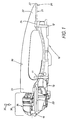
- the outside door handle shown in the door comprises a carrier 10, which by not shown in detail on the recognizable in Fig. 1 rear 21 of the door determining door panel 20 is attached.
- a handle 30 which is bow-shaped and preferably consists of a pull-folding handle.
- This handle 30, not shown in Fig. 2 is, is indicated by a dash-dotted lines, here inclined running Hinge axis 33 at the marked there with 11 and 12 bearing lobes stored. This happens at least at the bearing lobe 11 indirectly, namely about a there pivotally mounted lever 13.
- the lever 13 is here as "swingarm” educated. In the present case is also on the other bearing lobes 12 a short lever.
- the door panel 20 initially has two recesses 23, 24, through which the Handle 30 with connection parts not shown in detail at its two ends of the handle 31, 32 protrudes in the case of installation.
- the one handle end 31 is with his Attachment part attached to the free end 14 of the lever 13, what the hole-shaped Fixing point 15 in the arm in Fig. 2 can be seen.
- Another, further ahead lying attachment point on the arm of the lever 13 is not visible. in the the present case is the other end of the handle 32 with a connection at the top mentioned short lever of the bearing lobe 12 connected.
- Fig. 1 and 4 housing 34 mounted which in the present case also not shown in detail Lock cylinder includes.
- This housing is, in the sense of Einsteckpfeils 35 of the outside of the door inserted into the carrier 10 and fixed there.
- This case 34 occupies the space 36 adjacent to the handle 30. In this room 36 can also suitable cover parts sitting on the housing 34, which is one with the handle 30th consistent, compliant, pleasing appearance of the invention Justify door handle.
- the carrier 10 has a in Fig. 2 recognizable receptacle 16.
- the inserted position of the housing 34 in this Pickup 16 is shown in FIG. There, the housing 34 protrudes with its inner end 37 on the back of the carrier 10 out and acts with a special Retaining element 25 together, the appearance and operation in Connection with FIGS. 2 and 3 can be seen.
- FIG. 2 shows the installation position of the carrier 10 about this, as already mentioned, to attach to the back 21 of the door panel 20.
- the Retaining element 25 consists of a leaf spring, the dot-dashed lines in the figures highlighted and provided with a V-shaped crank 26.
- the Leaf spring is fixed with its one, fixed end 27 in the carrier 10 and cooperates with their opposite free spring end with the lever 13 together. she is in their end portion provided with a cutout 28 bounded by an edge 17 is.
- the lever 13 has a shoulder 18, which in the installed position of the wearer 10, seen on the door panel 20 from the front of the door, behind the leaf spring crank 26 is located.
- the crank 26 can be resilient on the horizontal arm support the lever or come to rest next to the arm of the lever 13.
- the housing 34 is again in the opposite direction to Einsteckpfeil 35 pulled out of the carrier 10.
- the leaf spring is free again and goes, due to their elasticity automatically in their operative position shown in FIG. 2 on.
- the lever 13 again in his from Fig. 3 apparent Ausschwenklage 13 ' brought so engages behind the rear shoulder 18 of the lever, the cutting edge 17 in the leaf spring. This happens again completely automatically.
- the leaf spring is then readily usable again for a new installation of the handle 30. Special Operations for securing the lever 13 in the Ausschwenklage 13 'are at the invention dispensable.
- the holding element 25 in other Way could be trained. It could e.g. from locking lugs and locking projections consist, if necessary, with the carrier 11 on the one hand and the lever 13th on the other hand are integrally formed. Instead of resilient tongues od. Like. One could also elastically longitudinally displaceable elements, such as a spring-loaded slide, use, in a comparable with Fig. 3 mounting position the lever 13 in secures its Ausschwenklage and the other hand, when inserting the housing 34 is set by this ineffective.
Landscapes
- Lock And Its Accessories (AREA)
Description
- Fig. 1
- die Draufsicht auf den erfindungsgemäßen Türgriff, wobei der Verlauf eines die Außenseite der Tür bestimmenden Türblechs strichpunktiert veranschaulicht ist,
- Fig. 2-4
- rückwärtige perspektivische Ansichten des in Fig. 1 gezeigten Schlosses, in denen der Handgriff nicht mit eingezeichnet worden ist, und zwar in drei verschiedenen Stellungen der Bauteile.
- 10
- Träger
- 11
- erster Lagerlappen an 10 für 30
- 12
- zweiter Lagerlappen an 10 für 30
- 13
- Hebel für 30
- 13'
- montagefreundliche Ausschwenkstellung von 13 für 30
- 14
- freies Ende von 13
- 15
- hintere Befestigungsstelle an 13 für 31
- 16
- Aufnahme in 10 für 34
- 17
- Kante von 28
- 18
- Schulter von 13
- 19
- Befestigungsstelle von 10 an 20
- 20
- Tür, Türblech
- 21
- Rückseite von 20
- 22
- Schauseite von 20
- 23
- erste Aussparung in 20
- 24
- zweite Aussparung in 20
- 25
- Halteelement, Blattfeder
- 26
- Verkröpfung von 25
- 27
- festes Ende von 25
- 28
- Ausschnitt in 25
- 30
- Handgriff, Zieh-Klappgriff
- 31
- erstes Griffende von 30
- 32
- zweites Griffende von 30
- 33
- Scharnierachse von 30
- 34
- Gehäuse
- 35
- Einsteckpfeil von 34 in 10
- 36
- Raum für 34 neben 30
- 37
- Innenende von 34
Claims (4)
- Türaußengriff, insbesondere für Fahrzeuge, mit einem auf der Rückseite (21) der Tür (20) befestigbaren Träger (10),
mit einem auf der Schauseite (22) der Tür (20) anordbaren Handgriff (30), der aus seiner Ruhelage an der Tür (20) durch eine Zieh- oder Klappbewegung in eine Betätigungslage bezüglich der Schlossglieder überführbar ist,
wobei der Handgriff (30) mit an seinen beiden Griffenden (31, 32) befindlichen Anschlüssen Türaussparungen (23, 24) durchgreift
und mindestens das eine Griffende (31) des Handgriffs (30) an einem schwenkbar am Träger (10) gelagerten (11) Hebel (13) angeschlossen ist
und der Anschluss des Griffendes (31) am Hebel (13) durch eine der Türaussparung (23) nahe Ausschwenklage (13') des Hebels ermöglicht oder zumindest begünstigt wird,
und mit einem von der Schauseite (22) der Tür (20) aus in den Träger (10) einsteckbaren Gehäuse (34),
wobei das Gehäuse (34) im Einsteckfall am Träger (10) befestigt ist und bedarfsweise einen auf die Schlossglieder einwirkenden Schließzylinder aufweist,
dadurch gekennzeichnet , dass zwischen dem Träger (10) und dem Hebel (13) ein zwischen einer wirksamen Halteposition und einer unwirksamen Freigabeposition umsteuerbares Halteelement (25) angeordnet ist,
dass beim Einbau des Trägers (10) an der Tür (20) das Halteelement (25) zum Anschluss des Handgriffs (30) sich zunächst in seiner Halteposition befindet, wo es den Hebel in dessen Ausschwenkstellung (13') festhält,
und dass das Gehäuse (34) beim Einstecken (35) in den Träger (10) das Halteelement (25) selbsttätig in dessen Freigabeposition überführt, wo der Hebel (13) freigegeben ist. - Türaußengriff nach Anspruch 1, dadurch gekennzeichnet, dass das Halteelement (25) aus einer Blattfeder besteht, die in ihrer Halteposition eine Schulter (18) hintergreift.
- Türaußengriff nach Anspruch 2, dadurch gekennzeichnet, dass die Blattfeder in ihrem Endbereich mit einem Ausschnitt (28) versehen ist,
welcher in der Ausschwenkstellung (13') die von der Rückfläche des Hebels gebildete Schulter (18) hintergreift. - Türaußengriff nach Anspruch 2 oder 3, dadurch gekennzeichnet, dass die Blattfeder am Träger (10) befestigt (27) ist und ein federndes verkröpftes Ende (26) aufweist, welches in den Weg der Einsteckbewegung (35) des Gehäuses (34, 37) hineinragt
und dass das eingesteckte Gehäuse (34, 37) das federnde Ende (26) der Blattfeder so weit zurückbiegt, bis es nicht mehr in den Schwenkbewegungsweg der am Hebel (13) sitzenden Schulter (18) hineinragt.
Applications Claiming Priority (3)
| Application Number | Priority Date | Filing Date | Title |
|---|---|---|---|
| DE19940379 | 1999-08-25 | ||
| DE19940379A DE19940379C2 (de) | 1999-08-25 | 1999-08-25 | Türaußengriff, insbesondere für Fahrzeuge |
| PCT/EP2000/007725 WO2001014666A1 (de) | 1999-08-25 | 2000-08-09 | Türaussengriff, insbesondere für fahrzeuge |
Publications (2)
| Publication Number | Publication Date |
|---|---|
| EP1206616A1 EP1206616A1 (de) | 2002-05-22 |
| EP1206616B1 true EP1206616B1 (de) | 2005-01-12 |
Family
ID=7919605
Family Applications (1)
| Application Number | Title | Priority Date | Filing Date |
|---|---|---|---|
| EP00954612A Expired - Lifetime EP1206616B1 (de) | 1999-08-25 | 2000-08-09 | Türaussengriff, insbesondere für fahrzeuge |
Country Status (7)
| Country | Link |
|---|---|
| US (1) | US6619709B1 (de) |
| EP (1) | EP1206616B1 (de) |
| JP (1) | JP5057317B2 (de) |
| CN (1) | CN1313691C (de) |
| DE (2) | DE19940379C2 (de) |
| ES (1) | ES2231236T3 (de) |
| WO (1) | WO2001014666A1 (de) |
Families Citing this family (19)
| Publication number | Priority date | Publication date | Assignee | Title |
|---|---|---|---|---|
| DE10037912A1 (de) | 2000-08-03 | 2002-02-14 | Huf Huelsbeck & Fuerst Gmbh | Türbeschlag zur Außenbetätigung einer Tür, insbesondere einer Fahrzeugtür |
| DE10037913C2 (de) * | 2000-08-03 | 2002-06-20 | Huf Huelsbeck & Fuerst Gmbh | Türbeschlag zur Außenbetätigung einer Tür, insbesondere einer Fahrzeugtür |
| DE10123826A1 (de) * | 2001-05-16 | 2002-11-21 | Valeo Sicherheitssysteme Gmbh | Türaußengriff für die Fahrzeugtür eines Kraftfahrzeuges |
| DE10126045A1 (de) | 2001-05-29 | 2002-12-12 | Huf Huelsbeck & Fuerst Gmbh | Türaußengriff-Bausatz, insbesondere für Fahrzeuge |
| DE10129112B4 (de) * | 2001-06-16 | 2005-02-17 | Itw Automotive Products Gmbh & Co. Kg | Türgriff für Automobile |
| DE10141430A1 (de) * | 2001-08-23 | 2003-03-13 | Valeo Sicherheitssysteme Gmbh | Türaußengriff für die Fahrzeugtür eines Kraftfahrzeuges |
| EP2290175B1 (de) * | 2003-05-09 | 2016-12-21 | Honda Lock Mfg. Co., Ltd. | Türgriffvorrichtung für Fahrzeuge |
| DE10359022A1 (de) * | 2003-12-15 | 2005-08-11 | Huf Hülsbeck & Fürst Gmbh & Co. Kg | Türaußengriff und Verfahren zum automatischen Sperren der Schwenkbewegung eines Tütaußengriffs bei einem Seitenaufprall |
| JP2005299085A (ja) * | 2004-04-06 | 2005-10-27 | Honda Motor Co Ltd | ドアアウトサイドハンドル |
| JP4536580B2 (ja) * | 2004-05-13 | 2010-09-01 | 株式会社ニフコ | 自動車のドアハンドル装置 |
| SE530091C2 (sv) * | 2004-06-30 | 2008-02-26 | Volvo Lastvagnar Ab | En dörrmodul och ett förfarande för att hos en fordonsdörr sammankoppla ett manöverorgan hos en stängnings- och öppningsmekanism och ett handtag |
| DE102004037983B3 (de) * | 2004-08-05 | 2006-01-12 | Huf Hülsbeck & Fürst Gmbh & Co. Kg | Vorrichtung zur Betätigung von Schlössern an Türen oder Klappen von Fahrzeugen |
| JP4534662B2 (ja) * | 2004-08-23 | 2010-09-01 | アイシン精機株式会社 | 車両用ドアハンドル |
| DE102004044758A1 (de) * | 2004-09-16 | 2006-04-06 | Volkswagen Ag | Lagerbügel |
| JP4789642B2 (ja) * | 2006-02-02 | 2011-10-12 | 株式会社ニフコ | ドアハンドル装置 |
| DE102007008548B4 (de) * | 2007-02-21 | 2010-04-01 | Daimler Ag | Türgriff für einen Kraftwagen |
| DE102009032324A1 (de) * | 2009-07-09 | 2011-01-13 | Huf Hülsbeck & Fürst Gmbh & Co. Kg | Türaußengriff, insbesondere für Fahrzeuge |
| JP5958939B2 (ja) * | 2013-07-25 | 2016-08-02 | 株式会社ホンダロック | 車両用ドアのハンドル装置 |
| DE102014000407A1 (de) | 2014-01-17 | 2015-07-23 | Huf Hülsbeck & Fürst Gmbh & Co. Kg | Kraftfahrzeugtürgriff |
Family Cites Families (12)
| Publication number | Priority date | Publication date | Assignee | Title |
|---|---|---|---|---|
| FR2149005A5 (de) * | 1971-08-12 | 1973-03-23 | Peugeot & Renault | |
| FR2644199B1 (fr) * | 1989-03-10 | 1991-05-17 | Renault | Commande de serrure de vehicule |
| US5101597A (en) * | 1991-08-06 | 1992-04-07 | General Motors Corporation | Door handle bracket attachment for vehicle door |
| US5174619A (en) * | 1991-11-25 | 1992-12-29 | Bender Frederick F | Tailgate handle assembly with sliding and pivoting lever |
| US5238276A (en) * | 1992-12-21 | 1993-08-24 | Chrysler Corporation | Vehicle handle attaching arrangement |
| US5340174A (en) * | 1993-04-12 | 1994-08-23 | Chrysler Corporation | Mounting arrangement for vehicle door handle |
| EP0646688B1 (de) * | 1993-10-05 | 1996-12-18 | YMOS AKTIENGESELLSCHAFT Industrieprodukte | Aussengriffanordnung für eine Tür, insbesondere eine Kraftfahrzeugtür |
| DE4443117B4 (de) * | 1994-12-02 | 2005-03-03 | Ewald Witte Gmbh & Co Kg | In eine Öffnung einer Tür, insbesondere Kraftfahrzeug-Tür einsetzbarer Griffbeschlag |
| DE4445320B4 (de) * | 1994-12-03 | 2005-04-28 | Ewald Witte Gmbh & Co Kg | In eine Öffnung einer Tür, insbesondere Kraftfahrzeug-Tür, einsetzbarer Griffbeschlag |
| FR2729697A1 (fr) * | 1995-01-25 | 1996-07-26 | Valeo Securite Habitacle | Poignee de porte de vehicule automobile a montage rapide par systeme coin-came |
| JP3386333B2 (ja) * | 1997-05-20 | 2003-03-17 | 株式会社アルファ | 自動車用ドアハンドル装置 |
| US6059329A (en) * | 1998-03-13 | 2000-05-09 | Adac Plastics Inc. | Door handle assembly with self-actuated mounting |
-
1999
- 1999-08-25 DE DE19940379A patent/DE19940379C2/de not_active Expired - Fee Related
-
2000
- 2000-08-09 DE DE50009233T patent/DE50009233D1/de not_active Expired - Lifetime
- 2000-08-09 WO PCT/EP2000/007725 patent/WO2001014666A1/de not_active Ceased
- 2000-08-09 EP EP00954612A patent/EP1206616B1/de not_active Expired - Lifetime
- 2000-08-09 JP JP2001518519A patent/JP5057317B2/ja not_active Expired - Fee Related
- 2000-08-09 US US10/069,610 patent/US6619709B1/en not_active Expired - Lifetime
- 2000-08-09 ES ES00954612T patent/ES2231236T3/es not_active Expired - Lifetime
- 2000-08-09 CN CNB008120048A patent/CN1313691C/zh not_active Expired - Fee Related
Also Published As
| Publication number | Publication date |
|---|---|
| CN1371446A (zh) | 2002-09-25 |
| WO2001014666A1 (de) | 2001-03-01 |
| JP2003507607A (ja) | 2003-02-25 |
| JP5057317B2 (ja) | 2012-10-24 |
| DE19940379A1 (de) | 2001-04-12 |
| DE50009233D1 (de) | 2005-02-17 |
| ES2231236T3 (es) | 2005-05-16 |
| DE19940379C2 (de) | 2001-07-12 |
| US6619709B1 (en) | 2003-09-16 |
| EP1206616A1 (de) | 2002-05-22 |
| CN1313691C (zh) | 2007-05-02 |
Similar Documents
| Publication | Publication Date | Title |
|---|---|---|
| DE19940379C2 (de) | Türaußengriff, insbesondere für Fahrzeuge | |
| DE60020755T2 (de) | Griff für einen Kraftfahrzeugflügel mit verbesserten Blockierungsmitteln für ein Aussenteil | |
| EP2654506B1 (de) | ÖFFNUNGS- UND SCHLIEßVORRICHTUNG FÜR BEWEGBARE MÖBELTEILE UND AUSSTOßVORRICHTUNG | |
| EP1066439B1 (de) | Betätigungsvorrichtung für ein türschloss mit klappbeweglichem griff, insbesondere für ein fahrzeugschloss | |
| DE102017117722A1 (de) | Türgriffanordnung für ein Kraftfahrzeug | |
| WO2016145465A1 (de) | Befestigungsvorrichtung zum lösbaren befestigen einer frontblende an einer schublade | |
| EP1500760A1 (de) | Türaussengriff-Baugruppe, insbesondere für Fahrzeuge | |
| EP0875177A2 (de) | Öffnungs- und Schliessmechanismus für einen Auszug eines Möbelelementes | |
| EP3894253B1 (de) | Kraftfahrzeug-klappen-system | |
| DE202012002867U1 (de) | Schloss mit Drehriegel | |
| EP3472414B1 (de) | Kraftfahrzeug-griffanordnung | |
| DE102010061483A1 (de) | Öffnungs- und Schließvorrichtung für bewegbare Möbelteile und Ausstoßvorrichtung | |
| EP1262615B1 (de) | Türaussengriff-Bausatz, insbesondere für Fahrzeuge | |
| EP2654504B1 (de) | ÖFFNUNGS- UND SCHLIEßVORRICHTUNG FÜR BEWEGBARE MÖBELTEILE | |
| DE19924028A1 (de) | Kraftfahrzeugtür | |
| DE4445320A1 (de) | In eine Öffnung einer Tür, insbesondere Kraftfahrzeug-Tür, einsetzbarer Griffbeschlag | |
| DE202008015463U1 (de) | Vorrichtung zur Abfrage der Position eines Schlossriegels | |
| DE102018104398A1 (de) | Möbel oder Haushaltsgerät und Verfahren zur Montage einer Funktionseinheit eines Schubelements in einem Möbel oder Haushaltsgerät | |
| DE102008033417A1 (de) | Fenster, Tür, Klappenanordnung oder dergleichen an einem Wohnaufbau eines Reisemobils oder an einem Wohnwagen | |
| DE602005000110T2 (de) | Mechanismus zum Öffnen und Schliessen einer Kraftfahrzeugtür | |
| DE10035468B4 (de) | An einer Tür montierbarer Griffbeschlag, insbesondere für Fahrzeuge | |
| EP1580352B1 (de) | Betätigungsvorrichtung für Türen oder Klappen | |
| EP3203001A1 (de) | Arretiervorrichtung für einen türöffner | |
| DE4016285A1 (de) | Schubriegelverschluss | |
| EP1430810A1 (de) | Ausstossvorrichtung |
Legal Events
| Date | Code | Title | Description |
|---|---|---|---|
| PUAI | Public reference made under article 153(3) epc to a published international application that has entered the european phase |
Free format text: ORIGINAL CODE: 0009012 |
|
| 17P | Request for examination filed |
Effective date: 20020215 |
|
| RBV | Designated contracting states (corrected) |
Designated state(s): DE ES FR GB IT |
|
| GRAP | Despatch of communication of intention to grant a patent |
Free format text: ORIGINAL CODE: EPIDOSNIGR1 |
|
| GRAP | Despatch of communication of intention to grant a patent |
Free format text: ORIGINAL CODE: EPIDOSNIGR1 |
|
| GRAS | Grant fee paid |
Free format text: ORIGINAL CODE: EPIDOSNIGR3 |
|
| GRAA | (expected) grant |
Free format text: ORIGINAL CODE: 0009210 |
|
| AK | Designated contracting states |
Kind code of ref document: B1 Designated state(s): DE ES FR GB IT |
|
| REG | Reference to a national code |
Ref country code: GB Ref legal event code: FG4D Free format text: NOT ENGLISH |
|
| REF | Corresponds to: |
Ref document number: 50009233 Country of ref document: DE Date of ref document: 20050217 Kind code of ref document: P |
|
| REG | Reference to a national code |
Ref country code: IE Ref legal event code: FG4D Free format text: GERMAN |
|
| GBT | Gb: translation of ep patent filed (gb section 77(6)(a)/1977) |
Effective date: 20050420 |
|
| REG | Reference to a national code |
Ref country code: ES Ref legal event code: FG2A Ref document number: 2231236 Country of ref document: ES Kind code of ref document: T3 |
|
| ET | Fr: translation filed | ||
| PLBE | No opposition filed within time limit |
Free format text: ORIGINAL CODE: 0009261 |
|
| STAA | Information on the status of an ep patent application or granted ep patent |
Free format text: STATUS: NO OPPOSITION FILED WITHIN TIME LIMIT |
|
| 26N | No opposition filed |
Effective date: 20051013 |
|
| PGFP | Annual fee paid to national office [announced via postgrant information from national office to epo] |
Ref country code: GB Payment date: 20120823 Year of fee payment: 13 |
|
| PGFP | Annual fee paid to national office [announced via postgrant information from national office to epo] |
Ref country code: IT Payment date: 20120806 Year of fee payment: 13 |
|
| GBPC | Gb: european patent ceased through non-payment of renewal fee |
Effective date: 20130809 |
|
| PG25 | Lapsed in a contracting state [announced via postgrant information from national office to epo] |
Ref country code: IT Free format text: LAPSE BECAUSE OF NON-PAYMENT OF DUE FEES Effective date: 20130809 |
|
| PG25 | Lapsed in a contracting state [announced via postgrant information from national office to epo] |
Ref country code: GB Free format text: LAPSE BECAUSE OF NON-PAYMENT OF DUE FEES Effective date: 20130809 |
|
| REG | Reference to a national code |
Ref country code: DE Ref legal event code: R084 Ref document number: 50009233 Country of ref document: DE |
|
| REG | Reference to a national code |
Ref country code: FR Ref legal event code: PLFP Year of fee payment: 16 |
|
| REG | Reference to a national code |
Ref country code: FR Ref legal event code: PLFP Year of fee payment: 17 |
|
| REG | Reference to a national code |
Ref country code: FR Ref legal event code: PLFP Year of fee payment: 18 |
|
| REG | Reference to a national code |
Ref country code: FR Ref legal event code: PLFP Year of fee payment: 19 |
|
| PGFP | Annual fee paid to national office [announced via postgrant information from national office to epo] |
Ref country code: DE Payment date: 20180727 Year of fee payment: 19 Ref country code: FR Payment date: 20180823 Year of fee payment: 19 Ref country code: ES Payment date: 20180917 Year of fee payment: 19 |
|
| REG | Reference to a national code |
Ref country code: DE Ref legal event code: R119 Ref document number: 50009233 Country of ref document: DE |
|
| PG25 | Lapsed in a contracting state [announced via postgrant information from national office to epo] |
Ref country code: FR Free format text: LAPSE BECAUSE OF NON-PAYMENT OF DUE FEES Effective date: 20190831 Ref country code: DE Free format text: LAPSE BECAUSE OF NON-PAYMENT OF DUE FEES Effective date: 20200303 |
|
| REG | Reference to a national code |
Ref country code: ES Ref legal event code: FD2A Effective date: 20210105 |
|
| PG25 | Lapsed in a contracting state [announced via postgrant information from national office to epo] |
Ref country code: ES Free format text: LAPSE BECAUSE OF NON-PAYMENT OF DUE FEES Effective date: 20190810 |