EP1203960A2 - Dispositif de palier à roulement et anneau avec un capteur pour le dispositif de palier à roulement - Google Patents
Dispositif de palier à roulement et anneau avec un capteur pour le dispositif de palier à roulement Download PDFInfo
- Publication number
- EP1203960A2 EP1203960A2 EP01126318A EP01126318A EP1203960A2 EP 1203960 A2 EP1203960 A2 EP 1203960A2 EP 01126318 A EP01126318 A EP 01126318A EP 01126318 A EP01126318 A EP 01126318A EP 1203960 A2 EP1203960 A2 EP 1203960A2
- Authority
- EP
- European Patent Office
- Prior art keywords
- sensor
- rolling bearing
- detecting
- sensor according
- ring
- Prior art date
- Legal status (The legal status is an assumption and is not a legal conclusion. Google has not performed a legal analysis and makes no representation as to the accuracy of the status listed.)
- Granted
Links
Images


Classifications
-
- F—MECHANICAL ENGINEERING; LIGHTING; HEATING; WEAPONS; BLASTING
- F16—ENGINEERING ELEMENTS AND UNITS; GENERAL MEASURES FOR PRODUCING AND MAINTAINING EFFECTIVE FUNCTIONING OF MACHINES OR INSTALLATIONS; THERMAL INSULATION IN GENERAL
- F16C—SHAFTS; FLEXIBLE SHAFTS; ELEMENTS OR CRANKSHAFT MECHANISMS; ROTARY BODIES OTHER THAN GEARING ELEMENTS; BEARINGS
- F16C41/00—Other accessories, e.g. devices integrated in the bearing not relating to the bearing function as such
- F16C41/004—Electro-dynamic machines, e.g. motors, generators, actuators
-
- F—MECHANICAL ENGINEERING; LIGHTING; HEATING; WEAPONS; BLASTING
- F16—ENGINEERING ELEMENTS AND UNITS; GENERAL MEASURES FOR PRODUCING AND MAINTAINING EFFECTIVE FUNCTIONING OF MACHINES OR INSTALLATIONS; THERMAL INSULATION IN GENERAL
- F16C—SHAFTS; FLEXIBLE SHAFTS; ELEMENTS OR CRANKSHAFT MECHANISMS; ROTARY BODIES OTHER THAN GEARING ELEMENTS; BEARINGS
- F16C19/00—Bearings with rolling contact, for exclusively rotary movement
- F16C19/52—Bearings with rolling contact, for exclusively rotary movement with devices affected by abnormal or undesired conditions
- F16C19/525—Bearings with rolling contact, for exclusively rotary movement with devices affected by abnormal or undesired conditions related to temperature and heat, e.g. insulation
-
- F—MECHANICAL ENGINEERING; LIGHTING; HEATING; WEAPONS; BLASTING
- F16—ENGINEERING ELEMENTS AND UNITS; GENERAL MEASURES FOR PRODUCING AND MAINTAINING EFFECTIVE FUNCTIONING OF MACHINES OR INSTALLATIONS; THERMAL INSULATION IN GENERAL
- F16C—SHAFTS; FLEXIBLE SHAFTS; ELEMENTS OR CRANKSHAFT MECHANISMS; ROTARY BODIES OTHER THAN GEARING ELEMENTS; BEARINGS
- F16C19/00—Bearings with rolling contact, for exclusively rotary movement
- F16C19/52—Bearings with rolling contact, for exclusively rotary movement with devices affected by abnormal or undesired conditions
- F16C19/527—Bearings with rolling contact, for exclusively rotary movement with devices affected by abnormal or undesired conditions related to vibration and noise
-
- F—MECHANICAL ENGINEERING; LIGHTING; HEATING; WEAPONS; BLASTING
- F16—ENGINEERING ELEMENTS AND UNITS; GENERAL MEASURES FOR PRODUCING AND MAINTAINING EFFECTIVE FUNCTIONING OF MACHINES OR INSTALLATIONS; THERMAL INSULATION IN GENERAL
- F16C—SHAFTS; FLEXIBLE SHAFTS; ELEMENTS OR CRANKSHAFT MECHANISMS; ROTARY BODIES OTHER THAN GEARING ELEMENTS; BEARINGS
- F16C33/00—Parts of bearings; Special methods for making bearings or parts thereof
- F16C33/30—Parts of ball or roller bearings
- F16C33/58—Raceways; Race rings
- F16C33/583—Details of specific parts of races
- F16C33/586—Details of specific parts of races outside the space between the races, e.g. end faces or bore of inner ring
-
- F—MECHANICAL ENGINEERING; LIGHTING; HEATING; WEAPONS; BLASTING
- F16—ENGINEERING ELEMENTS AND UNITS; GENERAL MEASURES FOR PRODUCING AND MAINTAINING EFFECTIVE FUNCTIONING OF MACHINES OR INSTALLATIONS; THERMAL INSULATION IN GENERAL
- F16C—SHAFTS; FLEXIBLE SHAFTS; ELEMENTS OR CRANKSHAFT MECHANISMS; ROTARY BODIES OTHER THAN GEARING ELEMENTS; BEARINGS
- F16C41/00—Other accessories, e.g. devices integrated in the bearing not relating to the bearing function as such
- F16C41/007—Encoders, e.g. parts with a plurality of alternating magnetic poles
-
- F—MECHANICAL ENGINEERING; LIGHTING; HEATING; WEAPONS; BLASTING
- F16—ENGINEERING ELEMENTS AND UNITS; GENERAL MEASURES FOR PRODUCING AND MAINTAINING EFFECTIVE FUNCTIONING OF MACHINES OR INSTALLATIONS; THERMAL INSULATION IN GENERAL
- F16C—SHAFTS; FLEXIBLE SHAFTS; ELEMENTS OR CRANKSHAFT MECHANISMS; ROTARY BODIES OTHER THAN GEARING ELEMENTS; BEARINGS
- F16C41/00—Other accessories, e.g. devices integrated in the bearing not relating to the bearing function as such
- F16C41/008—Identification means, e.g. markings, RFID-tags; Data transfer means
-
- F—MECHANICAL ENGINEERING; LIGHTING; HEATING; WEAPONS; BLASTING
- F16—ENGINEERING ELEMENTS AND UNITS; GENERAL MEASURES FOR PRODUCING AND MAINTAINING EFFECTIVE FUNCTIONING OF MACHINES OR INSTALLATIONS; THERMAL INSULATION IN GENERAL
- F16C—SHAFTS; FLEXIBLE SHAFTS; ELEMENTS OR CRANKSHAFT MECHANISMS; ROTARY BODIES OTHER THAN GEARING ELEMENTS; BEARINGS
- F16C43/00—Assembling bearings
- F16C43/04—Assembling rolling-contact bearings
-
- G—PHYSICS
- G01—MEASURING; TESTING
- G01P—MEASURING LINEAR OR ANGULAR SPEED, ACCELERATION, DECELERATION, OR SHOCK; INDICATING PRESENCE, ABSENCE, OR DIRECTION, OF MOVEMENT
- G01P3/00—Measuring linear or angular speed; Measuring differences of linear or angular speeds
- G01P3/42—Devices characterised by the use of electric or magnetic means
- G01P3/44—Devices characterised by the use of electric or magnetic means for measuring angular speed
- G01P3/443—Devices characterised by the use of electric or magnetic means for measuring angular speed mounted in bearings
-
- F—MECHANICAL ENGINEERING; LIGHTING; HEATING; WEAPONS; BLASTING
- F16—ENGINEERING ELEMENTS AND UNITS; GENERAL MEASURES FOR PRODUCING AND MAINTAINING EFFECTIVE FUNCTIONING OF MACHINES OR INSTALLATIONS; THERMAL INSULATION IN GENERAL
- F16C—SHAFTS; FLEXIBLE SHAFTS; ELEMENTS OR CRANKSHAFT MECHANISMS; ROTARY BODIES OTHER THAN GEARING ELEMENTS; BEARINGS
- F16C19/00—Bearings with rolling contact, for exclusively rotary movement
- F16C19/02—Bearings with rolling contact, for exclusively rotary movement with bearing balls essentially of the same size in one or more circular rows
- F16C19/04—Bearings with rolling contact, for exclusively rotary movement with bearing balls essentially of the same size in one or more circular rows for radial load mainly
- F16C19/06—Bearings with rolling contact, for exclusively rotary movement with bearing balls essentially of the same size in one or more circular rows for radial load mainly with a single row or balls
-
- F—MECHANICAL ENGINEERING; LIGHTING; HEATING; WEAPONS; BLASTING
- F16—ENGINEERING ELEMENTS AND UNITS; GENERAL MEASURES FOR PRODUCING AND MAINTAINING EFFECTIVE FUNCTIONING OF MACHINES OR INSTALLATIONS; THERMAL INSULATION IN GENERAL
- F16C—SHAFTS; FLEXIBLE SHAFTS; ELEMENTS OR CRANKSHAFT MECHANISMS; ROTARY BODIES OTHER THAN GEARING ELEMENTS; BEARINGS
- F16C2226/00—Joining parts; Fastening; Assembling or mounting parts
- F16C2226/30—Material joints
-
- F—MECHANICAL ENGINEERING; LIGHTING; HEATING; WEAPONS; BLASTING
- F16—ENGINEERING ELEMENTS AND UNITS; GENERAL MEASURES FOR PRODUCING AND MAINTAINING EFFECTIVE FUNCTIONING OF MACHINES OR INSTALLATIONS; THERMAL INSULATION IN GENERAL
- F16C—SHAFTS; FLEXIBLE SHAFTS; ELEMENTS OR CRANKSHAFT MECHANISMS; ROTARY BODIES OTHER THAN GEARING ELEMENTS; BEARINGS
- F16C2300/00—Application independent of particular apparatuses
- F16C2300/02—General use or purpose, i.e. no use, purpose, special adaptation or modification indicated or a wide variety of uses mentioned
Definitions
- the present invention relates to a rolling bearing device having a sensor for detecting vibration (acceleration), temperature, rotational speed, humidity (moisture) and the like, and a ring with the sensor for used with the rolling bearing device.
- the rolling bearings which are used for reducing rotation resistance, have been used in various fields, such as industrial equipment, vehicles, airplanes, and power plants.
- the rolling bearing will be vibrated when the rotating shaft is eccentric and be heated through the rotation friction. The vibration and temperature will adversely affect the lifetime of the bearing.
- a water-soluble cutting lubricant is frequently used in machining work. Accordingly, sometimes the bearing part receives a splash of it, which contains water.
- the rolling bearing is mounted on a machine used outdoors, such an automobile, a railroad car, or a construction machine, the bearing is frequently splashed with water when it runs in the rain or on a road with puddles.
- a measurement which has been taken for preventing the rolling surfaces of the raceway and the rolling elements from rusting is to use water-proof shields made of rubber or the like, which is slidably fitted to the inner and outer rings. Even in the case of the bearing having the water-proof shield, when weather conditions change, in particular when temperature rapidly changes, water enters the inside of the water-proof shield in the form of vapor, so that dew condensation will form on the rolling surfaces of the raceway and the rolling elements, sometimes.
- the vibration, temperature, rotational speed or humidity sensors as general-purpose parts are separately provided.
- a sensor suitable for a rolling bearing to be used is selected from among those sensors, and attached to the outer peripheral surface of the bearing. A signal derived from the sensor thus attached is led out to a necessary part by way of a wire.
- a general-purpose vibration sensor including an acceleration meter, a general-purpose temperature sensor including a thermocouple, a rotational speed sensor including an encoder and the like are connected, by wires, to an instrument mounted on a housing which accommodates the rolling bearing device.
- vibration, temperature and rotational speed of the bearing are indirectly detected through the housing.
- those general-purpose sensors are mounted on the rolling bearing, and signals representative of vibration, temperature and rotational speed are directly detected.
- a space used for mounting the sensors is formed in advance in the housing or the shaft.
- Threshold values are set for the vibration and temperature. When the measured vibration and temperature exceed the threshold values, signals representative of those measured ones are output to the instrument.
- Those general-purpose sensors are large in size. Because of this, a rolling bearing to which the sensors are mounted has a large protruded part at which the sensors are mounted. The protruded part is likely to restrict a freedom in laying out parts. Allowing for this, it is necessary to determine a configuration of the bearing and the layout of the sensors. The wiring ranging from those sensors to the instrument is also required. To mount those bearings with sensor, the machining work of the housing and the shaft increases.
- the existing equipment e.g., industrial equipment
- it is essential to grasp a running status of the automated equipment in a remote control manner.
- the bearing in the existing equipment into a bearing with sensor
- it is required to greatly alter the bearing and its vicinal structure since the conventional bearing with sensor is not interchangeable with another.
- Some types of shafts reject the mounting of the sensors thereon.
- the vibration sensor is constructed mainly with an accelerometer, and its detection has a directivity. Accordingly, when it is located apart from an object to be detected, the detection is likely to contain noticeable noise. In the case of the temperature sensor, with increase of a distance of the sensor to a heat source, its thermal conduction time becomes longer, and the sensing operation is affected by another heat source or sources, resulting in producing an incorrect sensed value. Also for the humidity detecting, it is necessary to detect humidity within the bearing space located inside the bearing; otherwise, it is impossible to correctly evaluate a degree of water entrance.
- an encoder is frequently attached to the shaft.
- the encoder is used for a sensor for detecting a rotational speed for the purpose of controlling the rotational speed of the shaft.
- a sensor for detecting vibration or temperature is provided for monitoring an operating condition of the bearing and the device including the bearing.
- the encoder for detecting a rotational speed of the shaft and the sensor for detecting vibration or temperature receive electric power from a power source, which is separately provided. Further, the detected signals of the rotational speed, vibration, temperature and the like are outputted by wires.
- wires must be used for supplying electric power from the separately provided power source to the encoder for detecting a rotational speed of the shaft and the sensor for detecting vibration or temperature. Those wires must be taken out every time the maintenance or replacement of the bearing and its vicinal portion is carried out. A complicated mechanism is required for supplying electric power to the sensor provided on the rotating part.
- the power source is preferably incorporated into the bearing.
- An example of the bearing containing an electric generator therein is disclosed in JP-A-6-200929.
- the electric generator includes a comb-shaped iron core having a plurality of threads radially arranged from the inner part of the bearing toward the outer part, a coil wound around the bottoms each between the adjacent threads, a plurality of magnets located while being confronted with the bottoms of the iron core, and a ring which has cuts arranged at intervals equal to the threads of the iron core and rotates at a speed equal to that of the bearing between the iron core and the magnets.
- the ring rotates between the iron core and the magnets, magnetic lines developed from the magnets are induced into the ring to excite the threads of the iron core, whereby the rotating speed is detected and electric power is generated.
- an object of the present invention is to provide a rolling bearing with sensor and a ring with sensor for the rolling bearing device which minimizes the formation of any artificial part on a bearing mounting part of a bearing housing, and which may easily be attached to an equipment that already exists.
- Another object of the present invention is to provide a rolling bearing with sensor having a rotational speed sensor which does not need to supply electric power from an external power source, and is capable of detecting a rotational speed at high accuracy.
- a rolling bearing with sensor having inner and outer ring and rolling elements, wherein a sensor in which a detecting part and a circuit part are mounted on a printed circuit board, is provided on and along the inner or outer ring.
- a detecting circuit part is mounted on a printed circuit board, and the printed circuit board is mounted on the shield.
- the invention also provides a rolling bearing with sensor comprising: inner and outer rings; rolling elements; a sensor having a detecting part capable of detecting at least one of vibration, temperature, rotational speed or humidity, and a circuit part; and the circuit part being mounted on and along the inner or outer ring.
- the detecting part for detecting humidity is provided within a space defined by the inner and outer rings and the shield supported by the either of the inner and outer rings.
- the circuit part includes a transmitting part which converts a signal output from the detecting part into a radio wave signal, and transmits the converted radio wave signal. Further, it may include an ultrasonic wave generating part which converts a signal detected by the detecting part into an ultrasonic wave signal, and transmits the converted ultrasonic wave signal.
- a rolling bearing with sensor including; an inner ring; an outer ring; a plurality of rolling elements disposed between the inner and outer rings; a retainer for retaining the rolling elements; a sensor having a detecting part detecting at least one of a rotational speed, a vibration, a temperature and a humidity, a transmitting part transmitting an output of the detecting part or a signal obtained by processing the output, a control part controlling the transmitting part based on the output of the detecting part, and a power source for supplying a power to the detecting part, the transmitting part and the control part; and a receiving device disposed on a position apart from the transmitting part, for receiving the signal transmitted from the transmitting part.
- a ring with sensor for a rolling bearing in which a pair of raceway rings rotate relative to each other through rolling elements disposed therebetween, wherein the ring with sensor is disposed so as to rotate together with one of the raceway rings, and the ring with sensor includes: a detecting part detecting at least one of a rotation speed, a vibration, a temperature and a humidity; a transmitting part transmitting an output of the detecting part or a signal obtained by processing the output; a control part controlling the transmitting part based on the output of the detecting part; and a power source for supplying a power to the detecting part, the transmitting part and the control part.
- a bearing with sensor including: a plurality of rolling elements; first and second rings rotating relative to each other via the rolling elements; and an electric generator having an annular magnet disposed on the first ring and an annular conductor disposed on the second ring, the electric generator generating electric power by a relative rotation between the magnet and the conductor.
- a bearing 1 shown in Figs. 1A and 1B is a single-row deep groove ball bearing.
- the bearing 1 includes an outer ring 2 and an inner ring 3, which are examples of a bearing ring.
- An outer raceway 4, while being recessed, is formed at a central part of the inner peripheral surface of the outer ring 2.
- An inner raceway 5, while being recessed, is formed at a central part of the outer peripheral surface of the inner ring 3.
- a plurality of balls 6 as rolling elements are retained with a retainer 7 in the circumferential direction at equal intervals, while being equiangularly disposed and in rolling contact with the outer raceway 4 and the inner raceway 5.
- Shield mounting grooves 8a and 8b are respectively provided at the inner peripheral surfaces of both ends 2a and 2b of the outer ring 2 as viewed in the widthwise direction. Shields 9 are fitted to those grooves 8a and 8b.
- a sensor 11 is circumferentially disposed on and along the bottom surface 10a of the annular groove 10 in a state that the sensor 11 is located inside a prolongation of the side face 2c of the outer ring 2, and inside a prolongation of the outer peripheral surface 2d.
- the sensor 11 is molded by using an insulting material, e.g., a synthetic resin 12. To measure a temperature, it is preferable that a heat conductivity of the synthetic resin 12 is equal to that of a bearing member.
- the protective synthetic resin 12 for improving the anti-dust, humidity and oil properties of the sensor 11 fills the annular groove 10 and is formed in an annular shape. Its end faces and outer peripheral surface are continuous to and flush with the side face 2c and the peripheral surface 2d.
- the sensor 11 for detecting vibration or temperature is constructed such that a detectingpart 15 for detecting vibration or temperature and circuit components 14, such as resistors, capacitors and IC, which form and a circuit part 16 for outputting detected signals are mounted on a flexible printed circuit (FPC) board 13.
- FPC flexible printed circuit
- annular groove 24 is formed entirely over the inner peripheral surface of an inner ring 23, viz., the annular groove is not formed in the outer ring 22.
- a sensor 11 is circumferentially disposed on the bottom surface 24a of the annular groove 24 in a state that the sensor 11 is located inside a prolongation of the side face 23a of the inner ring 23, but outside a prolongation of the inner peripheral surface 23b.
- the sensor 11 is molded by using an insulating material, e.g., a synthetic resin 12.
- the protecting synthetic resin 12 fills the annular groove 24, and is annular in shape.
- the synthetic resin 12 is provided for improving the performances of the dust-proof, water-proof and oil-proof.
- the end face and the inner peripheral surface of it are flush with the side face 23a and the inner peripheral surface 23b, while being continuous to the latter.
- a heat conductivity of the synthetic resin 12 is equal to that of bearing member.
- the senor 11 is disposed without outward extension, when comparing with the conventional one. Therefore, there is no need for any special machining of the bearing housing.
- FIG. 3 A third embodiment of the present invention will be described with reference to Fig. 3.
- the sensor 11 is directly bonded to a bottom surface 10a of an annular groove 10, which is formed in the outer ring 2.
- an FPC (flexible printed circuit board) 13 of the sensor 11 is used as a bonding surface.
- the remaining portion of the embodiment is substantially the same as the corresponding one in the first embodiment, and hence equivalent portions are designated by like reference numerals and symbols used in the first embodiment, for simplicity of explanation.
- a fourth embodiment of the invention will be described with reference to Fig. 4.
- the sensor 11 is directly bonded to a bottom surface 24a of an annular groove 24, which is formed in the inner ring 23.
- an FPC 13 of the sensor 11 is used as a bonding surface.
- the remaining portion of the embodiment is substantially the same as the corresponding one in the second embodiment, and hence equivalent portions are designated by like reference numerals and symbols used in the second embodiment, for simplicity of explanation.
- the senor 11 is disposed within the annular groove 10 or 24. Accordingly, those embodiments may achieve the object of the present invention as the first and second embodiments do so. It is noted that in the bearing device 31 (41) of the third (fourth) embodiment, the sensor 11 is bonded. This feature brings about the following advantages. Its manufacturing is simpler than in the case where the sensor is molded by using synthetic resin filling the annular groove 10 (24). The manufacturing cost is reduced since the molding resin is not used. Further, the sensor 11 may be additionally used if necessary.
- a power source for the sensor 11 may be an external power source, and in this case, the external power source is connected to the sensor 11 by a power cable. Otherwise, a power source, together with the sensor 11, may be located within the annular groove 10 (24), and in this case, there is no need of using the power cable.
- Abearing 51 shown in Fig. 5 includes a surface-opposed generator 52, which is located between the outer ring 2 and the inner ring 3.
- the surface-opposed generator 52 includes a coil 53 and a magnet 54.
- a shield 9 is fitted into a groove 8a, which is formed in the inner peripheral surface in an end 2a of the outer ring 2 in the widthwise direction, and corresponds to the location of the annular groove 10.
- the magnet 54 is mounted on a holding plate 55, while being disposed in association with the coil 53.
- the holding plate 55 is fitted into a holding-plate mounting groove 56, which is formed in the outer peripheral surface of an end 3a of the inner ring 3 in the width direction.
- the generator 52 generates electricity and supplies it to the sensor 11.
- the remaining portion of the embodiment is substantially the same as the corresponding one in the first embodiment, and hence equivalent portions are designated by like reference numerals and symbols used in the first embodiment, for simplicity of explanation.
- the generator 52 supplies electric power to the sensor 11 even in such a case that it is difficult to supply electric power from an external power source to the sensor 11 or that it is difficult to locate a power source together with the sensor 11, within annular groove 10.
- the senor 11 is provided on the outer ring 2 as in the first embodiment. If required, it may be provided on the inner ring 23 as in the second embodiment. In this case, the coil 53 of the generator 52 is mounted on the holding plate 55 that is fitted to the inner ring 23, and the magnet 54 is mounted on the shield 9 that is fitted to the outer ring 22. As in the third and fourth embodiments, the sensor 11 may be bonded for fixation without molding.
- a bearing device 61 shown in Figs. 6A and 6B includes a recessed part 63 formed by cutting a part of the end face of an outer ring 62, which is fitted to the fixed housing A.
- a rotational speed sensor shown in Fig. 6C includes a rotational speed detecting part 18 and a detected part 17.
- the detected part 17 is constructed by a permanent magnet attached to an inner ring shoulder portion of a race side with respect to the shield 9, and an outer surface of said permanet megnet is alternately magnetized to have N poles and S poles.
- the rotational speed detecting part 18 is constructed by a hall element for detecting change of magnetic flux, attached to an inner surface of the shield 9 disposed on the same side as the detected part 17.
- the detected part 17 may be made of any one of a plastic magnet, a rubber magnet or a sintered magnet, and further may be made of a gearwheel or a pulser-ring, instead of the permanent magnet.
- the rotational speed detecting part may be of an active type such as MR, GMR or hall IC, or of a passive type with a coil. Further, when outer ring rotates, the rotational speed sensor can be structured such that the detected part 17 is attached to the outer ring 62 and the rotational speed detecting part 18 is attached to the inner surface of the shield 9 secured to the inner ring 3.
- a detecting part 15 of a sensor 64 which is for detecting a signal representative of vibration, temperature or like of the bearing device 61, is mounted on the recessed part 63.
- the detecting part 15 is disposed such that it is located inside a prolongation of the side face 62a of the inner ring 62, but outside a prolongation of the outer peripheral surface 62b.
- the detecting part 15 may be mounted on the recessed part 63 in such a manner that it is molded by using an insulating material, e.g., synthetic resin 12, as in the first and second embodiments, or that it is insulatedly bonded to a bottom surface 63a of the recessed part 63 as in the third and fourth embodiments.
- a circuit part 16 of the sensor 64 while being insulated, is directly bonded to one of shields 9, which are fitted into shield-mounting groove 8a and shield-mounting groove 8b formed respectively in both ends 62c and 62d of the outer ring 62 in the widthwise direction.
- the sensor 64 is constructed such that circuit components 14 and the like are mounted on an arcuate FPC 65 formed conforming to a shape of the shield 9.
- the detecting part 15 and the circuit part 16 are provided on one continuous FPC 65. Otherwise, the detecting part 15 and the circuit part 16 may be mounted on separate FPCs, respectively, and interconnected by wires.
- a power source may be an external power source connected to the sensor 64 by a power cable. Otherwise, a power source together with the sensor 64 may be located on the shield 9, and in this case, there is no need of using the power cable.
- a surface-opposed generator 54 as described in the fifth embodiment maybe used. The remaining portion of the embodiment is substantially the same as the corresponding one in the first embodiment, and hence equivalent portions are designated by like reference numerals and symbols used in the first embodiment, for simplicity of explanation.
- the mounting part of the sensor 64 is not limited to the above-mentioned one, but in a case where the outer ring serves as a rotating ring and the inner ring serves as a stational ring, a recess formed by cutting a part of the side face 3a of the inner ring 3 may be used for the sensor mounting part.
- a shield mounting groove (recess) is formed at the end 3b of the inner ring 3, and the shield is fitted into the groove, and the sensor 64 is mounted thereon.
- the bearing device 61 of the sixth embodiment may be formed by merely cutting a part for mounting the detecting part 15 of the sensor 64. Accordingly, there is no need of machining work of the housing A and the shaft S to which the bearing device 61 is to be mounted, whereby, the rolling bearing with sensor 61 requires the least machining work of the bearing.
- a rolling bearing with sensor 1 of the first embodiment is mounted on the housing A as shown in Fig. 7.
- the housing A is static and at least one of the ends of the housing is opened.
- the rotating shaft S is inserted through the inner ring 3 of the rolling bearing 1, fixed thereto to be rotatable.
- a wire W and a power cable E are connected to the sensor 11, which is fastened to the annular groove 10 of the outer ring 2 as the stational ring by molding.
- the rolling bearing with sensor 1 may be the bearing 31 of the third embodiment.
- the bearing 21 or 41 of the second or fourth embodiment is used and the wire W is connected thereto, so that vibration, temperature or the like of the inner ring 23 may be detected.
- the wire W and the power cable E derived from the circuit part 16 of the sensor 64 mounted on the shield 9 are wired along the housing A or the shaft S as a stational part.
- the bearing can output a signal, which is converted by the circuit part 16 of the sensor 11 (64).
- a power source (not shown) may be located outside by using the wire W and the power cable E as well.
- the power source together with the sensor 11 is located in the annular groove 10 (in the sixth embodiment, the sensor 64 is located on the shield 9), or when the surface-opposed generator 52 is provided as in the bearing device 51 of the fifth embodiment, there is no need of using the power cable E, to thereby reduce the number of wires extended from the rolling bearing with sensor 1.
- a seventh embodiment of the invention will be described with reference to Figs. 8 through 10.
- a rolling bearing with sensor 71 shown in Fig. 8 an outer ring 22 is fitted to a housing A, and a rotating shaft S is fitted into an inner ring 23.
- the housing A is opened at at least one end thereof.
- a sensor 72 which is mounted on the rotating ring of the bearing 71, i.e., on an annular groove 24 of an inner ring 23, includes a detecting part 15 for detecting vibration, and a transmitting part (radio wave generator part) 73 which converts a detecting signal into a radio wave R, and transmits it outside.
- a power source 74 for the sensor 72 is mounted in the annular groove 24.
- the detecting part 15 includes conductive electrodes 15b mounted on a movable part 15c and a fixed part 15d of a detecting main part 15a made of an elastic insulating material shown in Fig. 9A in such a manner as to oppose to each other.
- the movable part 15c has an elastic modulus selected so that the conductive electrodes 15b come in contact with each other when it receives a predetermined vibration acceleration.
- the transmitting part 73 includes circuit components 14 such as a capacitor 73a, a coil 73b, a variable resistor 73c, a variable capacitance diode 73d and the like.
- a composite capacitance value C of the capacitor 73a and the variable capacitance diode 73d is varied, when the reverse voltage applied to the variable capacitance diode 73d is varied by varying a resistance value of the variable resistor 73c. And, an oscillation frequency defined by the capacitance value C and a reactance value L of the coil 73b may be selected. In other words, even when a plurality of rolling bearings with sensor 71 are concurrently used, the signals produced from those bearings may be detected discriminately.
- the seventh embodiment may use a transmitting part 75 including a capacitor 75a and a coil 75b as shown in Fig. 10, and the transmitting circuit part 75 is of the fixed frequency type in which a capacitance value of the capacitor 75a and a reactance value of the coil 75b are arbitrarily selected for each rolling bearing 71. Accordingly, the transmitting circuit part 75 can be reduced in size. It is evident that the transmitting parts 73 and 75 are an example of the transmitting part, and those may be realized by other circuit arrangements.
- the detecting main part 15a may be structured by a thermostat, and then, the sensor emits a radio wave R when a predetermined temperature is detected.
- the sensor 72 includes the transmitting circuit part 73 (75), and is applicable to the bearing 61 of the sixth embodiment.
- the remaining portion of the embodiment is substantially the same as the corresponding one of the rolling bearing with sensor 21 in the second embodiment, and hence equivalent portions are designated by like reference numerals and symbols used in the second embodiment, for simplicity of explanation.
- the sensor 72 may be circumferentially bonded onto and along the bottom surface 24a of the annular groove 24 as in the bearing device 41 of the fourth embodiment.
- the sensor 11 of the rolling bearing with sensor 1, 31 or 51 of the first, third or fifth embodiment (the sensor 64 in the bearing device 61 of the sixth embodiment) is substituted by the sensor 72, and, in the rolling bearings with sensor 1 and 31, a power source is located in the annular groove 10 (on the shield 9 in the sixth embodiment).
- a detecting signal may be transmitted while being carried on a radio wave R.
- the transmitted signal is received by an antenna 76 located at a remote position, and transmitted through a demodulator 77 to a related control system.
- the rolling bearing 71 of the seventh embodiment transmits a detected signal as a radio wave R, there is eliminated the wires extended from the rolling bearing 71. Accordingly, vibration, temperature or the like of the rolling bearing may be detected in such a simple manner that the rolling bearing is mounted as in mounting the conventional one.
- the rolling bearing with sensor 71 of the embodiment may be used for detecting vibration, temperature or the like of the stational ring as well as those of the rotating ring.
- a bearing device 81 shown in Fig. 11 includes an outer ring 2 fitted to the inner surface of a housing A' tightly closed and an inner ring 3 fitted into a rotating shaft S.
- An annular groove 10 is formed in the outer ring 2.
- a sensor 82 is circumferentially fastened to the bottom surface 10a of the annular groove 10 by molding.
- the sensor 82 includes a detecting part 15 for detecting vibration, temperature or the like, and an ultrasonic wave output circuit part (ultrasonic wave generating part) 83 which converts a detecting signal into an ultrasonic wave signal U and outputs the converted one.
- the sensor 82 can include the ultrasonic wave output circuit part 83 applicable to the bearing 61 of the sixth embodiment.
- the remaining portion of the embodiment is substantially the same as the corresponding one of the bearing 51 of the fifth embodiment, and hence equivalent portions are designated by like reference numerals and symbols used in the fifth embodiment, for simplicity of explanation.
- the sensor 82 and a power source may be put in the annular groove 10, instead of the generator 52.
- the rolling bearing with sensor 21 of the second embodiment is used for the bearing 81
- the sensor 11 of the rolling bearing 21 is used for the sensor 82
- a power source is put in the annular groove 24 or a surface-opposed generator 52 is used as in the fifth embodiment.
- the ultrasonic wave signal U is received by an ultrasonic wave receiver 84.
- the ultrasonic wave receiver 84 is detachably mounted in a closed manner on an ultrasonic wave detecting surface provided on the outer surface of the housing A'.
- the received ultrasonic wave signal is transmitted to a related control system, by way of a demodulator 85.
- the sensor 82 can output detecting signals representative of vibration, temperature or the like in the form of the ultrasonic wave signals U even when the bearing device 81 is covered with the housing A'.
- the detecting part 15 is fastened to the raceway by molding or bonding, and the circuit part 16 is mounted on the shield 9. In either case, the detecting part 15 is mounted at a position inside an area surrounded by the prolongation of the end faces of the outer ring and the inner ring, a prolongation of the outer peripheral surface of the outer ring, and a prolongation of the inner peripheral surface of the inner ring. Therefore, there is no need for any special machining of the housing.
- a ninth embodiment of the invention will be described with reference to Figs. 12A to 12F.
- sensors 11, 64, 72 and 82 are directly bonded to the surfaces of the outer ring 92 and the inner ring 93, by using FPCs 13 and 65 as bonding surfaces.
- FPCs 13 and 65 bonding surfaces.
- the rolling bearing with sensor 91 of this embodiment requires a less machining work of the housing when comparing with the conventional one.
- a rolling bearing with sensor 101 shown in Fig. 13A includes an outer ring 102, an inner ring 103, and a sensor 105 for sensing a humidity in a space K surrounded preferably by water-proof shields 104.
- the outer ring 102 is fitted into the opened end of a housing A and fastened by a a fixing ring 106.
- the inner ring 103 is fitted to the outer peripheral surface of the rotating shaft S.
- a recess 107 as shown in Fig. 13B, is formed in a part of the end face of the outer ring 102, while extending in the circumferential direction.
- the sensor 105 includes a detecting part 108 and a circuit part 109, and receives electric power from a power source (e.g., a button shaped battery) 110 by way of a power cable E.
- a power source e.g., a button shaped battery
- the water-proof rubber shields 104 is fitted to the outer ring 102 and is slidably contacted with the inner ring 103, and the detecting part 108 is mounted on the inner surfaces 104a of the water-proof shields 104, viz. within a space K surrounded by the outer ring 102, the inner ring 103 and the water-proof shields 104.
- the circuit part 109 is disposed so that it is not protruded out of a recess 107 formed in the outer ring 102.
- the recess 107 to which the circuit part 109 has been mounted may be molded by using synthetic resin.
- the circuit part 109 may be mounted on an FPC, as in the sensors 11, 64, 72 and 82 in the first to ninth embodiments. Fabricating of the circuit part into an integrated circuit is more preferable since remarkable size reduction of it is realized.
- the electric power 110 is placed in a recess 111 formed at a part of the housing A in insulating and water-tight fashion.
- Grooves 112a and 112b for receiving the power cable E, are formed in the housing A and the fixing ring 106, while ranging from the recess 107 to the recess 111.
- the detecting part 108 of the sensor 105 includes two electrodes 113a and 113b formed in a comb shape, and a moisture-absorbing conductor 114 located between those electrodes 113a and 113b as shown in Fig. 14.
- the two electrodes 113a and 113b and the conductor 114 are mounted on an insulating substrate 115. Terminals 116a and 116b are mounted on the electrodes 113a and 113b, respectively.
- the moisture-absorbing conductor 114 is formed with a thin film made of porous ceramics, e.g., calcium phosphate, by coating sintering and drying process or vacuum deposition process. When the conductor 114 absorbs atmospheric moisture, electric resistance value between the two electrodes 113a and 113b varies.
- a variation of the electric resistance value in the detecting part 108 is detected in the form of a signal of a variation of humidity.
- a fixed voltage Vcc is applied to the electrode 113a of the detecting part 108, and a resistor "r" earthed is connected to the electrode 113b.
- a voltage Vl passing through the detecting part 108 is detected as a signal proportional to the humidity.
- the circuit part 109 shown in Fig. 15 includes a comparator circuit 109a for processing a signal derived from the detecting part 108, and a transmitting part 109b for generating a radio wave.
- a voltage Vl derived from the detecting part 108 is input to the comparator circuit 109a as an object voltage for comparison. Further, a reference voltage Vs is applied to the comparator circuit part 109a.
- the comparator circuit compares a threshold value defined by the reference voltage Vs with the voltage Vl whose value varies in accordance with a degree of moisture absorption by the detecting part 108.
- the comparator circuit 109a When the voltage varies to exceed the threshold value, the comparator circuit 109a outputs a signal to the transmitting circuit part 109b. Accordingly, the sensor 105 transmits a radio wave when the detected humidity exceeds the predetermined threshold value.
- the threshold value may be adjusted by changing the resistor "r", the reference voltage Vs and the like.
- the circuit part 109 operates such that a signal output from the detecting part 108 is compared with the threshold value, and a radio wave R is transmitted to a receiver (not shown) located outside on the basis of the comparison result. It is evident that the circuit arrangement of the circuit part 109 is not limited to that shown in Fig. 15.
- the tenth embodiment thus constructed is capable of detecting a humidity in the space surrounded by the outer ring 102, the inner ring 103 and the water-proof shields 104 of the rolling bearing with sensor 101.
- the special machining work of the bearing mounting part e.g., the bearing housing A, may be minimized, and the rolling bearing with sensor may readily be mounted on the existing equipment.
- an outer ring 122 is fitted into the end of the housing A, and an inner ring 103 is fitted to the outer peripheral surface of the rotating shaft S.
- the bearing 121 includes a sensor 105 for detecting a humidity.
- the circuit part 109 of the sensor 105 is mounted on an outer surface 104b of the water-proof shield 104, viz., a surface opposite to the inner surface 104a to which the detecting part 108 is mounted. As shown in Fig.
- a circuit part 109 includes a comparator circuit 109a for comparing a signal output from a detecting part 108 with a predetermined threshold value, and a transmitting circuit part 109b for transmitting a radio wave in response to a signal output from the comparator circuit 109a.
- the circuit part is mounted on the water-proof shields 104 along the circumferential direction thereof.
- the detecting part 108 and the circuit part 109 of the sensor 105 are interconnected by a wire W, which passes through the water-proof shields 104 in a watertight manner.
- the circuit part 109 may be mounted on an FPC, as in the sensors 11, 64, 72 and 82 in the first to ninth embodiments, or fabricated into an integrated circuit for further remarkable size reduction.
- Electric power of the sensor 105 is supplied from the power source 110 placed in the recess 111 of the housing A through the power cable E.
- the grooves 112a and 112b are formed in the housing A and the fixing ring 106, and a stepped part 112c is formed at a part of the outer ring 122. If the power cable E does not interfere with the fixing ring 106, the stepped part 112c of the outer ring 122 may be omitted, and hence no machining work is required for the outer ring 122.
- the eleventh embodiment is capable of detecting the humidity in the within a space K surrounded by the outer ring 122, the inner ring 103 and the water-proof shields 104 of the bearing 121.
- the special machining work of the bearing mounting part e.g., the bearing housing A, may be minimized, and the rolling bearing with sensor may readily be mounted on the existing equipment.
- the detecting part 108 and the circuit part 109 of the sensor 105 are both mounted on the water-proof shield 104, the assembling of the bearing 121 is easy.
- a rolling bearing with sensor 131 shown in Fig. 17A includes a sensor 105 for detecting the humidity, as in the tenth and eleventh embodiments.
- the circuit part 109 of the sensor 105 is mounted on the water-proof shield 104 as in the eleventh embodiment.
- the circuit part 109 may be mounted on an FPC, as in the sensors 11, 64, 72 and 82 in the first to ninth embodiments. Further, the circuit part may be fabricated into an integrated circuit for size reduction.
- the power source 110 is a solar battery. At a part of the raceway ring (an outer ring 132 in this case) to which the water-proof shields 104 are fastened, a stepped part 133 is formed to be flush with the outer surface 104b of the water-proof shields 104.
- the power source 110 of the solar battery is mounted over an area including the stepped part 133 and the water-proof shield 104. If the solar battery is configured along the circumferential direction of the water-proof shield 104, there is no need of forming the stepped part 133 of the outer ring 132.
- the twelfth embodiment is capable of detecting the humidity within a space K surrounded by the outer ring 132, the inner ring 103 and the water-proof shields 104 of the bearing 131.
- the special machining work of the bearing mounting part e.g., the bearing housing A, may be minimized, and the rolling bearing with sensor may readily be mounted on the existing equipment. Since the solar battery is used for the power source 110, no care must be taken of the occurrence of a worn battery.
- the detecting part 108 of the sensor 105 is located outside the space K defined by the outer ring 102 (122, 132), the inner ring 103, and the water-proof shields 104.
- the detecting part 108 may be located within the space K as in the cases of Figs. 12A and 12C in the ninth embodiment, if the size of it allows such doing of the detecting part. Specifically, it may be located on the inner peripheral surface of the outer ring 102 (122, 132) facing the space K or the outer peripheral surface of the inner ring 103 facing the space K.
- the detecting part 108 may be constructed so as to detect vibration, temperature or humidity.
- the single-row deep groove ball bearing is used for the rolling bearing. It will readily be understood that also when the invention is applied to other types of rolling bearings, such as a cylindrical roller bearing or a thrust ball bearing.
- the rolling bearing with sensor of the invention the special machining work of the bearing mounting part, e.g., the bearing housing, is minimized, and the rolling bearing with sensor may readily be mounted on the existing equipment.
- the sensor is mounted on the bearing whose vibration, temperature, humidity or the like is detected. Therefore, vibration, temperature, humidity or the like may be detected quickly and accurately.
- the senor includes the radio wave generating part or an ultrasonic wave generating part.
- the bearing assembling work is free from troublesome work of wiring or the like. Accordingly, the invention provides an easy-to-handle rolling bearing with sensor.
- a rolling bearing device 201 shown in Fig. 18 is provided between a housing A as a stational part and a rotating shaft S.
- the rolling bearing device 201 includes an outer ring 202 and an inner ring 203, which are examples of a raceway ring and, in particular, detects a vibration, a temperature, a rotational speed or the like of the outer ring 202 fitted to the housing A.
- the outer ring 202 is fitted to the end of the housing A, and held with a fixing ring 204 for preventing it from falling off.
- a recessed outer raceway 202a is formed at a central part of the inner peripheral surface of the outer ring 202.
- a recessed inner raceway 203a is formed at a central part of the outer peripheral surface of the outer ring 203.
- a plurality of balls 205 as rolling elements are retained with a retainer 206 in the circumferential direction at equal intervals while being in rollably contacted with the outer raceway 202a and the inner raceway 203a.
- Shield mounting grooves 202b are respectively provided on both ends of the outer ring 202 as viewed in the widthwise direction, at locations closer to the inner ring.
- Shields 207 are respectively fitted to and supported by the shield mounting grooves 202b in order to protect the rolling surfaces of the outer raceway 202a, the inner raceway 203a, and the balls 205.
- An arcuate recess 208 which continuously extends in the circumferential direction of the outer ring 202, is provided at a part of an end face of the outer ring 202.
- a sensor 209 is mounted within the arcuate recess 208 in such a fashion that the sensor 209 is not protruded out of the arcuate recess 208.
- the sensor 209 as shown in Fig. 19, includes a detecting part 210 for detecting an acceleration, temperature or rotational speed, a transmitting part 211 for transmitting a radio wave signal, and a control part 212 for controlling the transmitting part 211.
- the sensor 209 is supplied with electric power from a power source 213, e.g., a button-shaped battery, by way of a wire W.
- the power source 213 is placed within a recess 214 formed at a part of the housing A.
- a groove 215 is provided ranging from the arcuate recess 208 to the recess 214, and the wire W
- the detecting part 210 includes an acceleration sensor 216, a temperature sensor 217 and a rotating speed sensor 218.
- the acceleration sensor 216 is provided mainly for sensing a vibration, and may be a piezoelectric element which produces a potential difference in accordance with an acceleration variation caused by a vibration, or a strain gauge stuck onto a plate spring.
- the temperature sensor 217 may be a thermistor whose electric resistance varies with a temperature variation.
- the detecting part 210 may include either of the acceleration sensor 216, the temperature sensor 217 or the rotating speed sensor 218 according to uses of the rolling bearing device 201.
- the arcuate recesses 208 may be formed at a plurality of locations of the end face of the rolling bearing device 201. In this case, the sensors 209 may be independently located in those recesses 208, or the detecting parts 210 may be located in those recesses 208.
- the arcuate recess 208 is provided on the static side, and the sensor 209 and the power source 213 are placed in the recess 208 such that the sensor 209 and the power source 213 are not protruded out of the outer surfaces of the housing A and the rolling bearing device 201. Therefore, there is no need of providing any special space for the mounting of the sensor 209 in the housing A or the shaft S. Accordingly, the rolling bearing device 201 may be interchanged with a conventional bearing. Further, the least amount of machining is required for the rolling bearing device 201.
- a signal derived from the acceleration sensor 216 of the detecting part 210 is input to a comparator 220a in the control part 212, and is compared with a predetermined acceleration in the comparator.
- a signal derived from the temperature sensor 217 is input to a comparator 220b, and compared with a predetermined temperature by the comparator 220b. Either of the signals derived from the sensors exceeds a threshold value, the control part 212 judges that something is wrong with the bearing (or the device using the bearing).
- a transmitting part controller 222 Upon the judgement being an abnormality, a transmitting part controller 222 first turns on (closes) a switch 224, which is inserted in a path for supplying electric power to the transmitting part 211, in order to enable the transmitting part 211 to operate. Subsequently, the transmitting part controller 222 sends to the transmitting part 211 a signal for transmitting a radio wave signal R indicating that the acceleration sensor 216 or the temperature sensor 217 detected an abnormality of the bearing or the like. Then, the rotating speed at the detecting time of the abnormality may be simultaneously transmitted. Upon receipt of the signal, the transmitting part 211 transmits a radio wave signal R indicating that the acceleration sensor 216 or the temperature sensor 217 detected an abnormality of the bearing or the like. The radio wave signal R is received by a receiving device 219, which is located at a position spaced apart from the transmitting part 211.
- the rolling bearing device 201 operates such that when the acceleration sensor 216, the temperature sensor 217 or the rotating speed sensor 218 detects an abnormality of the bearing or the like, the transmitting part 211 sends a radio wave signal R indicating the abnormality occurrence, but when the acceleration sensor 16 or the temperature sensor 217 produces a normal output signal, the transmitting part 211 does not emit a radio wave signal R indicating the normality.
- Sensor-function checking device is further provided for informing that the sensor normally functions; it. sends a radio wave signal R indicating that the sensor normally functions, at a fixed time interval (of e.g., 24 hours) . Therefore, even in such a case that the sensor abnormally functions and fails to output an abnormality signal, there is no chance of making such a misjudgement that it normally functions.
- different identification signals such as audio signals different in frequency from each other
- the transmitting part 211 sends a radio wave R in only the following cases: 1) the sensor 209 detects an abnormality; and 2) the sensor 209 normally operates.
- the switch 224 for supplying electric power to the transmitting part 211 is in an OFF (open) state. Accordingly, no electric power is consumed in the transmitting part 211. Therefore, in a case where the power source 213 is a battery, the power consumption is lessened, and hence the battery once mounted is used for a long time.
- the sensor 209 may be further reduced in size and power dissipation by fabricating the detecting part 210, the control part 212 and the transmitting part 211 into an integrated circuit.
- the bearing abnormality is judged by comparing an output signal of the acceleration sensor 216 with the threshold value of acceleration, and comparing an output signal of the temperature sensor 217 with the threshold value of temperature.
- the output signals of the acceleration sensor 216, the temperature sensor 217 and the rotating speed sensor 218 are converted into digital signals. Variations of the acceleration and temperature, or the correlation between variations of the acceleration and temperature are judged to determine that the bearing (or the device using the bearing) is abnormal.
- a radio wave signal R indicating the result of the determination is transmitted from the transmitting part 211.
- the detecting part 210 forming the sensor 209, those circuits 220a, 220b and 222, and the power source 213 may be individually connected by the wire W, and insulated and bonded to the recess 208 of the outer ring. Those may be mounted on the flexible printed circuit board to form a sensor unit, to thereby facilitate the bonding work for fixing. It should be understood that the sensor 209 of the embodiment is presented by way of example, and an electrical arrangement of the sensor is not limited to that of block diagram shown in Fig. 20
- a bearing device 231 shown in Fig. 21A is arranged such that an outer ring 202 is fitted to the inner side of the end of a housing A as a stational part, and an inner ring 203 is fitted to the outer side of the end of a rotating shaft S.
- the bearing device 231 thus constructed serves as a rolling bearing device for detecting an acceleration, temperature or rotating speed of the inner ring 202.
- a recess 232 is formed in a part of the end face of the inner ring 203 along the circumferential direction of the inner ring 203.
- a sensor 209 is mounted in the recess 232.
- the power source 213 for supplying electric power to the sensor 209 is mounted on the end 233 of the shaft S, preferably, in a recess 234 formed at the center of the shaft S.
- a groove 235 is formed between the recess 232 of the inner ring 203 to which the sensor 209 is attached and the recess 234 in which the power source 213 is fitted, and a wire W is placed in the groove 235.
- a cover member 236 covering the end 233 of the shaft S is attached in order to prevent the inner ring from falling off, as shown in Fig. 21A.
- the cover member 236 also has a function to protect the power source 213, the wire W and the sensor 209. While the power source 213 and the wire W are arranged in the recess 234 and the groove 235 formed in the end 233 of the shaft S, those may be put in a recess and a groove formed in the inner side of the cover member 236, so that no machining of the shaft S is required.
- the bearing device 231 thus constructed, there is no need of machining the housing A, and is required less machining of the shaft S for the attachment of the bearing device to the shaft.
- the bearing device 231 thus constructed is capable of detecting an acceleration and a temperature of the inner ring 203 that is fitted to the rotating shaft S.
- the sensor 209 since the sensor 209 includes sensor-function checking device, the bearing device of the embodiment is capable of periodically and easily checking as to if the sensor 209 normally functions.
- a bearing device 241 shown in Fig. 22A is arranged such that an outer ring 202 is fitted to the inner side of a housing A as a stational part, and an inner ring 203 is fitted to the outer side of an intermediate part of a rotating shaft S.
- the bearing device 241 thus constructed serves as a rolling bearing device for detecting an acceleration or temperature of the inner ring 203.
- a recess 232 is formed in a part of the inner ring 203 while being opened to the inner peripheral surface of the inner ring 203.
- the recess 232 has a width extending along the circumferential direction and being longer than the depth of the inner ring 203.
- a sensor 209 is mounted in the recess 232.
- a power source 213 for supplying electric power to the sensor 209 is placed in a recess 243 formed in a part of the inner surface of a sleeve 242.
- a groove 244 for connecting the recess 243 to the recess 232 of the inner ring 203 is formed in the end 242a of the sleeve 242.
- a wire W for electrically connecting the power source 213 to the sensor 209 is placed in the groove 244.
- the power source 213 and the sensor 209, as shown in Fig. 22A, are protected by the sleeve 242.
- the bearing device 241 thus constructed is capable of detecting an acceleration, a temperature or a rotating speed of the inner ring 203 fitted to the shaft S, and may be provided at the intermediate part of the shaft S.
- the bearing device 241 does not require any special machining of the housing A and the shaft S. In this respect, the bearing device is readily applied to the already existing bearing. Further, as in the thirteenth embodiment, since the sensor 209 includes sensor-function checking device, the bearing device of the embodiment is capable of periodically and easily checking as to if the sensor 209 normally functions.
- FIG. 23A and 23B A sixteenth embodiment of the present invention will be described with reference to Figs. 23A and 23B. In the embodiment, equivalent portions are designated by like reference numerals used in the thirteenth to fifteenth embodiments.
- Abearing device 251 shown in Figs. 23A and 23B is arranged such that an outer ring 202 is fitted to the end of a housing A as a stational part, and an inner ring 203 is fitted to the outer side of an intermediate portion of a rotating shaft S.
- a detecting part 210 includes a temperature sensor 217, and has a function similar to that of the thirteenth embodiment.
- a part of the sensor 209 is protruded out of the outer surface of the bearing device 251.
- the protruded part of the sensor 209 usually faces the space, and is not protruded out of a prolongation of the outer surface of the fixing ring 204. As shown in Figs.
- the deteating part 210, the control part 212 and the transmitting part 211 while being arranged along the circumferential direction, are mounted on the shields 207 which is fitted to and supported by the outer ring 202.
- the power source 213 is provided on the housing A as in the thirteenth embodiment.
- the shields 207 are supported on the inner ring 203, it is preferable that a sleeve 242 is provided as in the fifteenth embodiment, and that the power source 213 is located on the shaft S side.
- any special machining of the bearing device is not required, and it may be mounted on the housing A with less machining of it.
- the bearing device 251 is capable of detecting a temperature of the bearing device 251. Further, as in the thirteenth embodiment, since the sensor 209 includes sensor-function checking device, the bearing device of the embodiment is capable of periodically and easily checking as to if the sensor 209 normally functions.
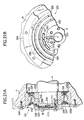
- a bearing device 261 shown in Fig. 24A is arranged such that the outer ring 202 is fitted to the inner side of the housing A as a stational part, and the inner ring 203 is fitted to the outer periphery side of the rotating shaft S as a rotating part.
- a sensor 209 is mounted in a recess 208 which is circumferentially formed at a part of the end face of the outer ring 202. The sensor is used for sensing an acceleration and a temperature of the outer ring 202.
- a power source 213 for supplying electric power to the sensor 209 is a small battery so configured as to be adaptable for its installing place and, together with the sensor 209, is mounted in the recess 208. Accordingly, in the embodiment, unlike the thirteenth embodiment, there is no need of mounting the power source 213 on the housing A, and hence of machining the housing A for its mounting. Further, the sensor 209 and the power source 213 are mounted so as not to be protruded out of the recess 208. Therefore, the bearing device 261 may easily be applied to an already existing apparatus by merely replacing a conventional bearing with the bearing device of the invention.
- the bearing device of the embodiment is capable of periodically and easily checking as to if the sensor 209 normally functions.
- a recess is formed at a part of the end face of the inner ring 203 along the circumferential direction, and the sensor 209 and the power source 213 are mounted in the recess.
- a bearing device 271 shown in Fig. 25A is arranged such that the outer ring 202 is fitted to the inner side of the housing A as a stational part, and the inner ring 203 is fitted to the outer peripheral side of the rotating shaft S.
- the sensor 209 is provided on the shields 207 supported on the outer ring 202, while being arranged in the circumferential direction as shown in Fig. 25B.
- a power source 213 for supplying electric power to the sensor 209 is a small battery so configured as to be adaptable for its installing place and, together with the sensor 209, is mounted in the recess 207.
- the bearing device 271 may easily be applied to an already existing apparatus by merely replacing a conventional bearing with the bearing device of the invention.
- the shields 207 may be supported on the inner ring 203.
- the bearing device of the embodiment is capable of periodically and easily checking as to if the sensor 209 normally functions.
- FIG. 26A and 26B A nineteenth embodiment of the present invention will be described with reference to Figs. 26A and 26B.
- equivalent portions are designated by like reference numerals used in the thirteenth to eighteenth embodiments.
- a bearing device 281 shown in Fig. 26A is arranged such that an outer ring 202 is fitted to the intermediate part of a housing A as a stational part, and an inner ring 203 is fitted to the outer peripheral side of an intermediate part of a shaft S as a rotating part.
- a detecting part 210 of a sensor 209 includes an acceleration sensor 216 and a temperature sensor 217, and is mounted in a recess 282 of the outer ring 202.
- the control part 212 and the transmitting part 211 of the sensor 209 are mounted on a shield 207 which is fitted to and supported on the outer ring 202 in such a manner as to arranged circumferentially.
- the acceleration sensor 216 and the temperature sensor 217 for sensing an acceleration and a temperature are placed at a location to be detected.
- a recess is formed in the inner ring 203.
- the detecting part 210 is mounted in the recess, and the control part 212 and the transmitting part 211 are circumferentially mounted on the shield 207 which is fitted to and supported on the inner ring 203.
- a power source 213 is a small battery so configured as to be adaptable for its installing place and, together with the control part 212 and the transmitting part 211, is mounted on the shield 207.
- a protecting member 283 is provided on the shield 207, for covering the control part 212, the transmitting part 211 and the power source 213.
- the protecting member 283 is preferably made of a material permitting radio wave to pass therethrough, such as a plastic material.
- a cover preferably a ring-like protecting cover (referred to as a protecting ring) is provided.
- an outer-ring protecting ring 284 is provided on the outer ring side
- an inner-ring protecting ring 285 is provided on the inner ring side.
- the outer-ring protecting ring 284 and the inner-ring protecting ring 285 are each wider than the width of the protruded part of the protecting member 283. Those are brought into engagement with'the outer ring 202 and the inner ring 203 with steps being formed therebetween. Accordingly, the detecting part 210 located in the recess 282 is covered with and protected by the outer-ring protecting ring 284. If required, the outer ring 202 and the inner ring 203 are previously selected in width so as to prevent the outer-ring protecting ring 284 from protruding out of the end faces of the outer ring 202 and the inner ring 203.
- the mounting of the bearing device 281 may be carried out without machining the housing A and the shaft S. Therefore, a conventional bearing may easily be replaced with the bearing device 281.
- the bearing device of the embodiment is excellent in durability since the sensor 209 and the power source 213 are protected by the protecting member 283 and the outer-ring protecting ring 284.
- the bearing device of the embodiment is capable of periodically and easily checking as to if the sensor 209 normally functions.
- the inside of the protecting member 283 is preferably molded of an insulating filling member, e.g., a synthetic resin, whereby the control part 212, the transmitting part 211, the power source 213 and the like are stably fixed.
- an insulating filling member e.g., a synthetic resin
- the shield 207 is provided so as to be fitted to the inner ring 203 on which the detecting part 210 is mounted.
- the control part 212 and the transmitting part 211 of the sensor 209 and the power source 213 are mounted on the shield 207.
- a bearing device 291 shown in Fig. 27A is arranged such that an outer ring 202 is fitted to the inner side of an intermediate part of a housing A as a stational part, and an inner ring 203 is fitted to the outer side of the intermediate part of a shaft S as a rotating part.
- a ring for outer ring 292, which is fastened to the outer ring 202 in a unitary form, is mounted on the end face of the outer ring 202.
- a ring for inner ring 293, which is fastened to the inner ring 203 in a unitary form, is mounted on the end face of the inner ring 203.
- the ring for inner ring 293 of which the width is equal to that of the ring for outer ring 292, is used. If required, this ring 93 for inner ring may be omitted.
- the ring for outer ring 292 includes a flange 94 formed integrally therewith, which extends toward the ring for inner ring 293 so as to cover the shield 207.
- the control part 212 and the transmitting part 211 of the sensor 209 and the power source 213 for supplying electric power to the sensor 209, as shown in Fig. 27B, are disposed along the circumferential direction in which the flange 294 expands, on a surface of the flange 294, which faces the shield 207, i.e., an inner surface 294a.
- the detecting part 210 of the sensor 209 is mounted in a recess 295, which is formed in a part of the ring 292 for outer ring.
- the ring 292 for outer ring is preferably made of a material, which permits the radio wave R emitted from the transmitting part 211 to pass therethrough, such as a plastic material.
- An antenna for transmitting the radio wave R may be mounted on the reverse side, i.e., an outer surface 294b, of the flange, which is a counterpart of the side of the flange on which the transmitting part 211 is mounted.
- the mounting of the bearing device 291 thus constructed may be carried out without machining the housing A and the shaft S. Therefore, the bearing of an existing apparatus may easily be replaced with the bearing device 291 to which the sensor 209 for sensing the vibration and temperature is mounted. Since the sensor 209 is mounted on the side of the ring 292 for outer ring, which faces the shield 207 and is protected against the outside, its durability is good.
- the control part 212 and the transmitting part 211 of the sensor 209, and the power source 213 may be mounted on an arcuate board, which is curved along the shape of the flange 294, viz., a flexible printed circuit board, and then stuck to the flange 294.
- the detecting part 210, together with the control part 212 and the transmitting part 211, may be mounted on the flange 294.
- a flange is formed integral with the ring for inner ring 293, while extending toward the ring for outer ring 292.
- the control part 212 and the transmitting part 211, and the power source 213 are mounted on the flange.
- the detecting part 210 of the sensor 209 is mounted in the recess formed at a part of the ring for inner ring 293.
- the senor 209 includes sensor-function checking device, as in the thirteenth embodiment. Therefore, the bearing device of the embodiment is capable of periodically and easily checking as to if the sensor 209 normally functions.
- the single-row deep groove ball bearing is used for a typical example of the rolling bearing. It will readily be understood that also when the invention is applied to other types of rolling bearings, such as a thrust ball bearing and a cylindrical roller bearing, rolling bearings each containing a sensor for sensing a vibration or a temperature, may be realized.
- a ring for outer ring 302 serving as a ring with sensor 301 shown in Fig. 28A is interference fitted to a housing A to which an outer ring 202 of a bearing 300 is interference fitted, and the ring with sensor 301 is movable together with the outer ring 202.
- a ring for inner ring 303 is provided in the end face of the inner ring 303.
- a flange 304 protruding toward the shaft S is formed on the inner periphery of a ring with sensor 301. As shown in Fig.
- a control part 212 and the transmitting part 211 of the sensor 209, and the power source 213 for supplying electric power to the sensor 209 are mounted on a surface of the flange 304 which faces the shields 207 of the bearing 300, i.e., an inner surface 304a, while being arranged in the circumferential direction in which the flange 304 expands.
- a detecting part 210 of a sensor 209 which includes an acceleration sensor 216 for sensing a vibration and a temperature sensor 217 for sensing a temperature, is mounted in a recess 305 formed at a part of the outer ring 301.
- An arcuate opening 306 is formed in the flange 304.
- the opening 306 expands in the circumferential direction in which the flange expands, and passes through the flange 304.
- the ring with sensor 301 may be made of a metallic material.
- the ring with sensor 301 is preferably made of a material permitting radio wave to pass therethrough, such as a plastic material or the antenna 307 is mounted on an outer surface 304b of the flange 304.
- the detecting part 210 may be mounted on the inner surface 304a of the flange 304.
- the sensor 209, the power source 213 and the antenna 307 may be mounted on a flexible printed circuit board, and then stuck to the inner surface 304a.
- the sensor 209, the power source 213 and the antenna 307 may be molded of non-conductive resin, whereby, the protection of the sensor 209 is secured.
- the ring with sensor 301 With the ring with sensor 301 thus constructed, there is no need of machining the housing A or the shaft S with the bearing 300 mounted thereon. Further, the existing bearings maybe used as they are, and the bearings used for the conventional apparatus may have useful effects as those by the thirteenth to twentieth embodiments described above.
- the sensor 209, the power source 213 and others are mounted on the inner surface 304a of the flange 304, and those are protected against the outside. In this respect, its durability is excellent.
- the ring with sensor having the flange projected toward the housing A is interference fitted to the shaft S to which the inner ring 203 is interference fitted, and the ring with sensor and the outer ring 202 are movable together with each other.
- the control part 212, the transmitting part 121 and the power source 213 are mounted on the flange of the ring with sensor, and the detecting part 210 of the sensor 209 is mounted in the recess formed at apart of the ring with sensor.
- the bearing device of the embodiment is capable of periodically and easily checking as to if the sensor 209 normally functions.
- the single-row deep groove ball bearing is used for a typical example of the rolling bearing, and the ring 301 having the sensors for sensing a vibration and temperature is discussed. It will readily be understood that also when the invention is applied to other types of rolling bearings, such as a thrust ball bearing and a cylindrical roller bearing, rolling bearings each containing a sensor for detecting a vibration or a temperature, may be realized.
- the invention succeeds in providing a rolling bearing device and a ring with sensor for the rolling bearing device in which there is no need of specially forming a large space for mounting the sensor in the housing or the shaft, and the least working of the bearing is required.
- a radio wave indicating that the sensor is normal is transmitted at fixed time intervals. Accordingly, one can readily know that the sensor normally functions.
- the rolling bearing with sensor 401 includes a plurality of balls 402 as rolling elements, and a pair of raceways, that is, an inner ring 403 being a first raceway and an outer ring 404 being a second raceway, those raceways rotating relative to each other via the balls 402 being interposed therebetween.
- the balls 402 are arranged in the circumferential direction Q at equal intervals within a retainer 405 (Fig. 30).
- a recessed inner raceway 403b is formed at a central part of the outer peripheral surface 403a of the inner ring 403. The balls 402 are in rolling contact with the inner raceway 403b.
- a recessed outer raceway 404b is formed at a central part of the outer peripheral surface 404a of the outer ring 404.
- the balls 402 are in sliding contact with the outer raceway 404b.
- the outer ring 404 is secured to the housing A, and the inner ring 403 supports the rotating shaft S.
- a first groove 406 is formed in one of the ends 403c of the outer peripheral surface 403a of the inner ring 403 as viewed in the width direction (in a direction P along the axial line of the shaft S), while extending over the entire circumference thereof.
- a first shield 407 is fitted to the first groove 406 thus formed.
- the first shield 407 is annularly formed while expanding in the radial direction and in the circumferential direction Q of the inner ring 403.
- Second shields 409 are respectively fitted into second grooves 408, which are formed in both ends 404c of an inner peripheral surface 404a of the outer ring 404.
- the second shields 409 are annularly formed in a state that it overlaps with the first shield 407 in the direction P along the axis of the shaft S, and expands in the radial direction and in the circumferential direction Q of the outer ring 404.
- the annular magnet 410 is mounted on an outer peripheral surface 407a (opposite to a surface facing the balls 402) of the first shield 407, which is perpendicular to the axial line of the shaft S.
- the magnet 410 extends along a direction of the outer peripheral surface 407a.
- the magnet 410 is magnetized to have N poles 410n and S poles 410s, which are alternately arranged in the circumferential direction Q of the inner ring 403 at equal intervals.
- the magnet 410 may be any one obtained by molding a rubber magnet and a plastic magnet containing ferrite powder, a rare earth magnet or a ferrite magnet, if it is a permanent magnet magnetized to have N poles and S poles being arranged in the circumferential direction Q.
- the first shield 407 when a magnetic circuit is formed by using a magnetic material in cooperation with the magnet 410 so as to intercept the magnetic lines, its magnetic influence on the rolling bearing with sensor 401 is lessened.
- the conductor 411 is mounted on the inside surface 409a of the second shield 409, which is confronted with the magnet 410, while being spaced from the latter by a fixed distance from the magnet 410 in the axial direction P of the shaft S.
- the conductor 411 is extended annularly along the magnet 410 in the circumferential direction Q, while being meandered to form rectangular parts radially arranged at intervals each equal to the pole-to-pole distance of the magnet 410.
- a recess 412 is formed in a part of the outer peripheral edge 404c of the outer ring 404, which corresponds to the second shield 409 to which the conductor 411 is mounted.
- a sensor 413 is mounted on a flat surface 412a of the recess 412, which is perpendicular to the axial line of the shaft S.
- the sensor 413 may be mounted on a flexible printed circuit board, and arranged along the cylindrical surface 412b of the recess 412.
- the recess 412 may be molded of resin and the like.
- the sensor 413 as shown in Fig. 31, includes a detecting part 414 for detecting vibration or temperature, a transmitting part 415 for transmitting a radio wave signal R, and a control part 416 for controlling the transmitting part 415 in accordance with the output signal of the detecting part 414.
- the control part 416 is connected to both ends 411a of the conductor 411, and a storage battery 417 which, together with the sensor 413, is placed in the recess 412, and includes a power source circuit (not shown).
- a specific example of the detecting part for detecting vibration is a vibration sensor having an acceleration sensor, which is constructed by a piezoelectric element or strain gauge.
- a specific example of the detecting part for detecting temperature is a temperature sensor containing a thermistor, a temperature sensing resister, a thermocouple or the like, or an IC temperature sensor, which, together with the circuit, is fabricated into an integrated circuit.
- the outer ring 404 is fixed to the housing A and the inner ring 403 is rotated together with the shaft S. That is, when the inner ring 403 and the outer ring 404 rotate relative to each other, the magnet 410, together with the inner ring 403, rotates with respective to the conductor 411, as shown in Fig. 32.
- the conductor 411 is meandered at intervals each equal to the pitch of the magnetic poles of the magnet 410.
- the conductor may be considered as a semicircular coil in which the winding directions of the rectangularly bent parts 411a of the conductor are alternately inverted.
- an electromotive force is generated so that current flows in such a direction as to cancel the magnetic field H, which passes through a space within each the rectangularly bent part 411a, viz., in a direction W at a moment shown in Fig. 32.
- the magnetic field H alternately varies with respective to the conductor 411.
- an electromotive force generated in the conductor 411 also alternately varies.
- an AC electromotive force appears at both ends 411a of the conductor 411.
- the magnet 410 and the conductor 411 cooperate to form an electric generator 418; viz., when the magnet and the conductor 411 rotate relative to each other, an electromotive force is generated.
- the magnet 410 and the conductor 411 are respectively provided in an annular shaped and rotate relative to each other, the electromotive force generated at both ends of the conductor has little variation even when the dimensional uniformity is lost to some extent as to the circularity of each of the magnet and the conductor, distance between them, pole-to-pole distance, meandering interval, and the like. Accordingly, a stable electric power is generated.
- conductor 411 Since conductor 411 is meandered in the radial direction, when it rotates relative to the magnet 410, an electromotive force is generated. When the conductor is meandered at intervals each equal to the pole-to-pole distance in the present invention embodiment, the electromotive force generated in the conductor 411 is uniform in phase, so that a more stable outputting of it is secured. Further, the conductor 411 is meandered while rectangularly bent in the embodiment, it crosses the magnetic field H developed by the magnet 410 over a broader area. As a result, a larger electromotive force is produced.
- the conductor 411 may be formed on a printed circuit board or a flexible printed circuit board by etching. In this case, it may be formed in the form of a multiple of layers. If either of coils formed as below is used, an electromotive force generated is large: a coil in which a conducting wire is plurally wound along the outer surface of the second shield in such a manner that it is meandered, while rectangularly bent, at intervals each equal to the pole-to-pole distance of the magnet; and a coil in which solenoids are arranged in the circumferential direction Q and along the outer surface of the magnet 410, each solenoid being such that the winding direction of the conducting wire is inverted at intervals each equal to the pole-to-pole distance of the magnet 410. If a ferromagnetic member, e.g., iron core, is located within each rectangularly bent part of the conductor or at the center of the solenoid, the generated electromotive force is further increased.
- a ferromagnetic member e.g., iron
- the second shield 409 on which the conductor 411 is mounted Since a magnetic field whose direction is inverted every pole of the magnet 410 successively passes through the second shield annularly shaped when the magnet 410 rotates relative to the second shield.
- the second shield it is preferable to make the second shield of a non-magnetic material, e.g., plastic or resin.
- a frequency of the AC electromotive force appearing at both ends 411a of the conductor 411 is proportional to the rotational speed of the bearing. This implies that the rotational speed of the bearing can be detected in a manner that a frequency of the electromotive force is detected by the control part 416, and the rotational speed of the bearing is obtained based on an output variation of the frequency.
- the magnet 410 and the conductor 411 are annular in shape and rotate relative to each other, the electromotive force appearing at both ends 411a of the conductor 411 has little variation even when the dimensional uniformity is lost to some extent as to the circularity of each of the magnet and the conductor, distance between them, pole-to-pole distance, meandering interval, and the like. Accordingly, the accuracy of detecting the rotational speed of the bearing, which is measured based on the electromotive force, has little variation.
- the AC electromotive force generated is rectified by a rectifying circuit contained in the control part 416, and the resultant is utilized for the electric power for the sensor 13.
- Information of vibration or temperature, detected by the detecting part 414 of the sensor 413, together with frequency information of the electromotive force generated in the conductor 411, is signal-processed by the control part 416, and subjected to comparison judging process, and the resultant is sent from the transmitting part 415 in the form of radio wave R. Accordingly, information about a operating state of the rolling bearing with sensor 401 may be obtained when the radio wave R is received by a receiver, which is separately provided at a location remote from the rolling bearing with sensor 401. Further, it is noted that the detecting information is output in a wireless manner. Because of this feature, there is eliminated troublesome work of connecting and disconnecting the wires every time the shaft S to which the rolling bearing with sensor 401 is mounted and its vicinal structure are disassembled or assembling.
- the storage battery 417 which, together with the sensor 413, is placed in the recess 412, is charged by an electric power generated through the rotation of the magnet 410 relative to the conductor 411, under control of a power source circuit of the control part 416.
- the rotational speed of the rolling bearing with sensor 401 decreases, and an electric power generated through the rotation of the magnet 10 relative to the conductor 411 is insufficient for the power consumption by the sensor 413, the storage battery 417 discharges electric power to make up for the deficiency of the electric power.
- the rolling bearing with sensor 401 is able to carry out the detecting operation reliably and accurately.
- a third shield (not shown) made of a magnetic material may be located as a back yoke at a position opposite to the first shield 407 with respective to the second shields 409. Then, since the influence of the external magnetic field on it is lessened even when the rotational speed is slow and the electromotive force is small, the rotational speed can be detected more accurately. In this case, it is preferable that the third shield is rotated with the inner ring on which the magnet 410 is supported, to avoid such an unwanted situation that eddy current is generated in the third shield and the shield is heated.
- a bearing device with sensor 421 according to a twenty-third embodiment will be described with reference to Figs. 33 and 34.
- equivalent portions are designated by like reference numerals used in the twenty-second embodiment.
- a magnet 422 of the bearing device with sensor 421 shown in Fig. 33 is annularly shaped while extending in a circumferential direction Q of the bearing device with sensor 421. Its outer peripheral surface 422a is supported on the first shield 407.
- a conductor 423 extends in a circumferential direction Q of the bearing device with sensor 421, while being rectangularly meandered along a cylindrical surface developed about the rotational axis of the inner ring 403 and at intervals each equal to the pole-to-pole distance of the magnet 410.
- the conductor 423 annularly extends while being spaced from the inner peripheral surface 422b of the magnet 422 by a fixed gap.
- the conductor 423 is located on the inner side of the magnet 422 as radially viewed. If required, the conductor 423 may be located on the outer side thereof.
- the magnet 422 and the conductor 423 maybe assembled at a good concentricity. Accordingly, if the magnet 422 and the conductor 423 are radially disposed in a state that the cylindrical surfaces of those members are confronted with each other, a variation of an electric power generated through the rotation of the magnet 422 relative to the conductor 423 is reduced.
- the magnet 410 and the conductor 411 are disposed along the rotating shaft as in the twenty-second embodiment. If so disposed, a variation of the electric power output is reduced.
- the first shield 407 on which the magnet 410 (422) of the rolling bearing with sensor 401 (421) is mounted, together with the shaft S, is fitted to the rotating inner ring 403, and the second shields 409 on which the conductor 411 (423) is mounted is fitted to the outer ring 409 fixed to the housing A.
- the magnet 410 (422) is provided fixed to the outer ring 404 and the conductor 411 (423) is provided so as to rotate with the inner ring 403.
- the conductor 411 (423) is fixed to the raceway on which the sensor 413 is mounted, and the magnet 410 (422) is disposed so as to rotate relative to the conductor 411 (423).
- an electromotive force appears between the both ends 411a of the conductor 411, and is supplied to the sensor 413, and the detecting information by the sensor 413 is sent by a radio wave R.
- the wiring from the rolling bearing with sensor 401 to exterior is not used, viz., a power cable E for operating the sensor, a communication cable for transmitting the information detected by the sensor, and the like are not used.
- a spindle unit with rotating speed sensor is provided which does not require the reconnection of the power source every time the tool is replaced with another.
- the sensor 413 is not protruded out of a region defined by the both end faces, and the outer and inner peripheries of the rolling bearing with sensor 401 (412). Therefore, the bearing device may easily be replaced with the existing bearing if any machining work is not done for its mounting.
- a frequency of AC electromotive force generated by the rolling bearing with sensor 401 (421) in the twenty-second (twenty-third) embodiment is proportional to a rotational speed of the shaft to which the rolling bearing with sensor 401 (421) is mounted, and an amplitude of the AC electromotive force is also proportional to the rotational speed of the shaft. Accordingly, if the rolling bearing with sensor 401 (421) is incorporated into an electric generator to be controlled in rotational speed, there is no need of using a frequency generator (FG) or a tachogenerator, which is provided separately from the electric generator for the purpose of detecting the rotational speed. This results in cost and size reduction of the electric generator.
- FG frequency generator
- a tachogenerator which is provided separately from the electric generator for the purpose of detecting the rotational speed. This results in cost and size reduction of the electric generator.
- the magnet 410 and the conductor 411 are disposed over the entire circumference. Accordingly, an AC electromotive force generated for each phase is averaged. Accordingly, even if error factors of the AC electromotive force exist, an frequency error of the AC electromotive force with respective to the rotational speed of the bearing is very small.
- Those error factors are magnetizing pitch (interval at which it is magnetized to N and S poles) of the magnet 410, magnetizing intensity, irregularity of magnetizing pitch (interval at which the conductor is meandered) of the magnet 410, misalignment of the magnet 410 with the conductor 411, and others.
- An electric generator which is small in rotational speed irregularity, and low in cost and size, may be realized if the rolling bearing with sensor 401 (421) is provided on the rotating shaft of an electric generator or the like, a frequency of an AC electromotive force generated by the rolling bearing with sensor 401 (421) and a reference frequency produced by a quartz vibrator are input to a PLL (phase locked loop) circuit, and a rotational speed of the electric generator is controlled in accordance with a phase difference.
- PLL phase locked loop
- the first and second shields or first to third shields as electric generators may be disposed outside the seals.
- an active type rotational speed sensor such as a Hall element (IC) or an MR element, additionally.
- the electric generator that is constructed with the annular magnet and conductor is stable in the frequency and amplitude of an AC electromotive force generated. Accordingly, it may be used as a stable source capable of supplying quality electric power.
- the mounting position of the power source 413 in each embodiment is not limited to the recess 412 formed at a part of the outer ring 404. If required, a recess is formed at a part of the inner ring 403. Further, it may be attached to the end face of the inner or outer ring.
- the invention succeeds in providing a rolling bearing with sensor having an electric generator and a sensor.
- the electric generator includes a bearing having a pair of raceway rings being rotatable relative to each other with the aid of rolling elements being interposed therebetween, an annular magnet supported on the first raceway ring of the bearing, N and S poles being alternately disposed in the circumferential direction of the bearing, and an annular conductor supported on the second raceway of the bearing, the annular conductor rotating relative to the magnet, thereby generating an electromotive force.
- the sensor detects a rotational speed of the first raceway ring relative to the second raceway ring on the basis of electric power output from the electric generator.
- the magnet and the conductor cooperate to provide a function of the electric generator, and also a function of a sensor for detecting a rotational speed of the bearing. Accordingly, the rolling bearing does not need the supply of electric power from an external power source in order to operate the sensor, and is capable of detecting a rotational speed of the bearing.
- the magnet is magnetized so as to have the N and S poles being arranged alternately and in the circumferential direction, is annular in shape and preferably arranged at equal intervals.
- the conductor, annularly shaped extends, while being meandered, in a direction in which the conductor crosses the magnetic lines developed from the magnet, specifically, in the radial direction of the bearing or in the axial direction of said bearing and along said magnet and a cylindrical surface developed about the rotational axis of the bearing.
- the magnet and the conductor are annularly shaped. Accordingly, when the magnet and the conductor rotate relative to each other, an electromotive force is always generated irrespective of their rotational positions.
- the electromotive force appearing at both ends of the conductor a little varies even when the dimensional uniformity is lost of the circularity deviation and concentricity of each of the magnet and the conductor, distance between them, pole-to-pole distance, meandering interval, and the like.
- the outputting of the electromotive force generated through the relative rotation of the magnet to the conductor is stabilized, and a rotational speed measured based on the electromotive force may be detected at high accuracy.
Landscapes
- Engineering & Computer Science (AREA)
- General Engineering & Computer Science (AREA)
- Mechanical Engineering (AREA)
- Physics & Mathematics (AREA)
- General Physics & Mathematics (AREA)
- Rolling Contact Bearings (AREA)
Applications Claiming Priority (10)
| Application Number | Priority Date | Filing Date | Title |
|---|---|---|---|
| JP2000338151 | 2000-11-06 | ||
| JP2000338151 | 2000-11-06 | ||
| JP2001007792 | 2001-01-16 | ||
| JP2001007792A JP2002206528A (ja) | 2000-11-06 | 2001-01-16 | センサ付き転がり軸受 |
| JP2001046674 | 2001-02-22 | ||
| JP2001046674 | 2001-02-22 | ||
| JP2001152805 | 2001-05-22 | ||
| JP2001152805 | 2001-05-22 | ||
| JP2001298353A JP2003097582A (ja) | 2001-09-27 | 2001-09-27 | センサ付軸受装置 |
| JP2001298353 | 2001-09-27 |
Publications (4)
| Publication Number | Publication Date |
|---|---|
| EP1203960A2 true EP1203960A2 (fr) | 2002-05-08 |
| EP1203960A3 EP1203960A3 (fr) | 2002-06-26 |
| EP1203960B1 EP1203960B1 (fr) | 2014-08-13 |
| EP1203960B2 EP1203960B2 (fr) | 2018-02-07 |
Family
ID=27531705
Family Applications (1)
| Application Number | Title | Priority Date | Filing Date |
|---|---|---|---|
| EP01126318.3A Expired - Lifetime EP1203960B2 (fr) | 2000-11-06 | 2001-11-06 | Dispositif de palier à roulement et anneau avec un capteur pour le dispositif de palier à roulement |
Country Status (2)
| Country | Link |
|---|---|
| US (2) | US6948856B2 (fr) |
| EP (1) | EP1203960B2 (fr) |
Cited By (17)
| Publication number | Priority date | Publication date | Assignee | Title |
|---|---|---|---|---|
| EP1293766A1 (fr) * | 2001-09-11 | 2003-03-19 | Nsk Ltd | Palier à roulement avec capteur de temperature et/ou de vibration |
| WO2007028575A1 (fr) * | 2005-09-08 | 2007-03-15 | Walter Dittel Gmbh | Système capteur |
| DE102007011733A1 (de) * | 2007-03-10 | 2008-09-11 | Ab Skf | Verfahren zum Betrieb eines Kompressors und Kompressor |
| FR2918172A1 (fr) * | 2007-06-27 | 2009-01-02 | Univ Reims Champagne Ardenne | Dispositif et procede de surveillance de l'etat vibratoire d'une machine tournante. |
| FR2925676A1 (fr) * | 2007-12-21 | 2009-06-26 | Snr Roulements Sa | Procede de detection et de quantification d'un ecaillage d'un assemblage pour le roulement d'essieu, et assemblage pour roulement d'essieu adapte pour la mise en oeuvre d'un tel procede |
| WO2010012277A1 (fr) * | 2008-07-31 | 2010-02-04 | Schaeffler Kg | Palier à roulement avec un dispositif magnétique |
| CN101818755A (zh) * | 2010-03-25 | 2010-09-01 | 重庆大学 | 一体耦合式智能监测轴承 |
| CN102705375A (zh) * | 2012-06-19 | 2012-10-03 | 宁波摩根轴承有限公司 | 一种轴承防尘盖 |
| FR3027977A1 (fr) * | 2014-10-30 | 2016-05-06 | Skf Ab | Palier a roulement avec bague exterieure en forme de troncon de sphere et avec un organe capteur |
| FR3030654A1 (fr) * | 2014-12-17 | 2016-06-24 | Skf Ab | Roulement avec unite de fonction et methode d'assemblage d'un tel roulement |
| US9733153B2 (en) * | 2013-10-31 | 2017-08-15 | Schaeffler Technologies AG & Co. KG | Device for measuring force in the rolling bearing by means of a sensor layer |
| EP3421830A4 (fr) * | 2016-04-01 | 2019-02-27 | NSK Ltd. | Palier équipé d'un capteur sans fil |
| EP3149365B1 (fr) * | 2014-05-27 | 2019-12-11 | Aktiebolaget SKF | Dispositif de scellement étanche et procédé pour sceller de manière étanche dans un milieu liquide |
| EP3597947A1 (fr) | 2018-07-18 | 2020-01-22 | NKE Austria GmbH | Système de surveillance de palier |
| CN112160983A (zh) * | 2020-10-10 | 2021-01-01 | 南通大学 | 一种可测内圈温度的智能轴承 |
| CN112196907A (zh) * | 2019-07-08 | 2021-01-08 | 斯凯孚公司 | 中心主轴单元 |
| US20230037144A1 (en) * | 2021-07-30 | 2023-02-02 | Shinko Electric Industries Co., Ltd. | Sensor module |
Families Citing this family (84)
| Publication number | Priority date | Publication date | Assignee | Title |
|---|---|---|---|---|
| DE10017572B4 (de) * | 2000-04-10 | 2008-04-17 | INSTITUT FüR MIKROTECHNIK MAINZ GMBH | Wälzlager mit fernabfragbaren Erfassungseinheiten |
| EP1329727A1 (fr) * | 2001-10-18 | 2003-07-23 | Nsk Ltd | Capteur de vitesse angulaire |
| FR2833663B1 (fr) * | 2001-12-19 | 2004-02-27 | Roulements Soc Nouvelle | Roulement comprenant un ensemble de transmission d'informations sans fil |
| US7256505B2 (en) * | 2003-03-05 | 2007-08-14 | Microstrain, Inc. | Shaft mounted energy harvesting for wireless sensor operation and data transmission |
| US7341321B2 (en) * | 2002-03-08 | 2008-03-11 | Ntn Corporation | Rotation detecting device and anti-skid braking system using the same |
| US6892587B2 (en) * | 2002-03-08 | 2005-05-17 | Ntn Corporation | Rotation detecting device and wheel support bearing assembly utilizing the same |
| FR2841990B1 (fr) * | 2002-07-02 | 2005-07-29 | Skf Ab | Dispositif de palier a roulement instrumente et moteur electrique ainsi equipe |
| JP4084617B2 (ja) * | 2002-08-23 | 2008-04-30 | パイオニア株式会社 | スイッチ装置、情報処理装置および再生装置 |
| US7184930B2 (en) * | 2002-08-30 | 2007-02-27 | Nsk Ltd. | Method and device for monitoring status of mechanical equipment and abnormality diagnosing device |
| DE10304592A1 (de) * | 2003-02-05 | 2004-08-19 | Fag Kugelfischer Ag | Messlager mit integriertem Datenerfassungs- und verarbeitungssystems |
| WO2004102018A1 (fr) * | 2003-05-13 | 2004-11-25 | Koyo Seiko Co., Ltd. | Roulement, systeme et procede de gestion pour ce roulement |
| DE10323889A1 (de) * | 2003-05-27 | 2004-12-16 | Ehrfeld Mikrotechnik Ag | Wälzlager mit Polymerelektronik |
| DE10344234A1 (de) * | 2003-09-24 | 2005-05-12 | Fag Kugelfischer Ag | Datenerfassungs- und Verarbeitungssystem für ein Wälzlager und Wälzlager mit einem solchen System |
| US7182519B2 (en) * | 2004-06-24 | 2007-02-27 | General Electric Company | Methods and apparatus for assembling a bearing assembly |
| DE102004054201A1 (de) * | 2004-11-10 | 2006-05-11 | Fag Kugelfischer Ag & Co. Ohg | Wälzlager mit in der Lagerringstirnseite integrierten Sensoren |
| JP2006153112A (ja) * | 2004-11-29 | 2006-06-15 | Jtekt Corp | 車輪用軸受装置 |
| DE112005003283T5 (de) * | 2004-12-28 | 2007-11-15 | Ntn Corp. | Wälzlager |
| US7214893B2 (en) * | 2005-02-15 | 2007-05-08 | Electric Arc Technologies, Llc | Load cell system |
| US20090097794A1 (en) * | 2005-03-24 | 2009-04-16 | Darrell Grayson Higgins | Gear Bearing |
| US7634913B2 (en) * | 2005-03-30 | 2009-12-22 | General Electric Company | Bearing assembly and method of monitoring same |
| US7523615B2 (en) * | 2005-03-30 | 2009-04-28 | General Electric Company | Telemetry system |
| US7878713B2 (en) * | 2005-08-22 | 2011-02-01 | Ntn Corporation | Sensor-equipped bearing for wheel |
| DE102005043773A1 (de) * | 2005-09-14 | 2007-03-15 | Man Roland Druckmaschinen Ag | Lager, insbesondere Druckmaschinenlager |
| ATE544654T1 (de) * | 2005-12-23 | 2012-02-15 | Asf Keystone Inc | Überwachungssystem für eisenbahnzüge |
| US7698962B2 (en) * | 2006-04-28 | 2010-04-20 | Amsted Rail Company, Inc. | Flexible sensor interface for a railcar truck |
| US20070277386A1 (en) * | 2006-05-31 | 2007-12-06 | Motorola, Inc. | Inclinometer or tilt switch with refined motion sensitivity |
| DE102006035703A1 (de) * | 2006-08-01 | 2008-02-07 | Schaeffler Kg | Vorrichtung zur Überwachung mindestens einer Betriebsgröße eines Radsatzlagers |
| US8246252B2 (en) * | 2006-09-06 | 2012-08-21 | Nsk Ltd. | Bearing apparatus |
| FR2910129B1 (fr) * | 2006-12-15 | 2009-07-10 | Skf Ab | Dispositif de palier a roulement instrumente |
| US8313240B2 (en) * | 2007-03-12 | 2012-11-20 | Aktiebolaget Skf | Sensorized bearing unit |
| JP2008268187A (ja) * | 2007-03-26 | 2008-11-06 | Nippon Steel Corp | 極低速回転機械の異常診断方法及び装置 |
| US8123411B2 (en) * | 2007-03-27 | 2012-02-28 | Ntn Corporation | Sensor-equipped bearing for wheel |
| FR2916814B1 (fr) * | 2007-05-29 | 2009-09-18 | Technofan Sa | Ventilateur avec moyens de detection de degradation de roulements |
| US20100218619A1 (en) * | 2007-10-22 | 2010-09-02 | The Timken Company | Drive torque sensing wheel end |
| DE102008008720A1 (de) * | 2008-02-12 | 2009-08-27 | Knorr-Bremse Systeme für Nutzfahrzeuge GmbH | Messvorrichtung zur Messung von relativen Drehgeschwindigkeiten mit drahtloser Signalübertragung |
| DE102008009283B4 (de) | 2008-02-15 | 2021-07-29 | Schaeffler Technologies AG & Co. KG | Radlagervorrichtung für ein Kraftfahrzeug |
| CN104709311B (zh) * | 2008-03-05 | 2020-12-04 | Skf公司 | 装置 |
| DE102008018547B4 (de) | 2008-04-12 | 2018-05-09 | Schaeffler Technologies AG & Co. KG | Lager mit einem Signalumwandler |
| JP2010038290A (ja) * | 2008-08-06 | 2010-02-18 | Ntn Corp | リユース軸受およびそのリユース方法 |
| KR101596395B1 (ko) * | 2008-11-05 | 2016-02-22 | 엔티엔 가부시키가이샤 | 센서가 장착된 차륜용 베어링 |
| JP5349157B2 (ja) | 2009-06-19 | 2013-11-20 | Ntn株式会社 | 回転検出装置および回転検出装置付き軸受 |
| US9640467B2 (en) * | 2009-08-05 | 2017-05-02 | Continental Teves Ag & Co. Ohg | Sensor arrangement and chip comprising additional fixing pins |
| US9097278B2 (en) * | 2010-07-02 | 2015-08-04 | Aktiebolaget Skf | Bearing ring with an additional component and method for producing such a bearing ring |
| DE102010047928A1 (de) * | 2010-10-08 | 2012-04-12 | Schaeffler Technologies Gmbh & Co. Kg | Wälzlager zum rotativen Lagern eines Maschinenelementes |
| DE102010049552B4 (de) * | 2010-10-25 | 2012-05-31 | Schaeffler Technologies Gmbh & Co. Kg | Wälzlagersensor, Wälzlager mit einem Wälzlagersensor und Anordnung eines Wälzlagersensors |
| US8876393B2 (en) * | 2010-11-30 | 2014-11-04 | Safran Power Uk Ltd. | Bearing enclosure with integrated wear detection |
| CN103384774B (zh) * | 2010-12-20 | 2016-01-20 | Skf公司 | 集成轴承的发电机 |
| BR112013033886A2 (pt) * | 2011-07-01 | 2017-02-14 | Krd Corp | conjunto de mancal |
| EP2764268B1 (fr) * | 2011-10-06 | 2015-08-12 | Aktiebolaget SKF (publ) | Construction de palier collecteur d'énergie thermoélectrique |
| CN104080568A (zh) * | 2011-12-20 | 2014-10-01 | Skf公司 | 通过闪光对接焊制造钢部件的方法以及使用该方法制得的部件 |
| CN104204564A (zh) * | 2012-01-26 | 2014-12-10 | Skf公司 | 具有磁性和/或电子元件的滚动轴承 |
| EP2932223B1 (fr) * | 2012-12-14 | 2017-02-15 | Aktiebolaget SKF | Ensemble capteur à fibre |
| DE102013004678A1 (de) * | 2013-03-19 | 2014-09-25 | Continental Teves Ag & Co. Ohg | Leiterplatte zum Anbinden eines Verformungssensor an eine Signalverarbeitungsschaltung |
| CN103711801B (zh) * | 2013-12-23 | 2016-04-13 | 大连理工大学 | 掘进机滚刀带复合传感器的轴承组件 |
| CN103837248B (zh) * | 2014-03-11 | 2016-09-21 | 中国航空动力机械研究所 | 轴承测温探针固定装置 |
| DE102014212124B3 (de) * | 2014-06-24 | 2015-05-21 | Schaeffler Technologies AG & Co. KG | Übertrager, Verfahren zu dessen Herstellung und Wälzlager mit integriertem Übertrager |
| JP6550219B2 (ja) * | 2014-08-06 | 2019-07-24 | Ntn株式会社 | 車輪用軸受装置 |
| DE102014217787A1 (de) | 2014-09-05 | 2016-03-10 | Schaeffler Technologies AG & Co. KG | Wälzlager mit einer elektrischen Schaltung sowie Herstellungsverfahren einer elektrischen Schaltung für ein Wälzlager |
| JP6149871B2 (ja) | 2015-01-15 | 2017-06-21 | 日本精工株式会社 | ワイヤレスセンサ付き軸受 |
| GB2534191A (en) * | 2015-01-16 | 2016-07-20 | Mahle Int Gmbh | Sliding bearing |
| ES2834909T3 (es) * | 2015-04-07 | 2021-06-21 | New Hampshire Ball Bearing Inc | Cojinete con sensor de desgaste |
| GB201506138D0 (en) * | 2015-04-10 | 2015-05-27 | Skf Ab | Capped bearing with vibration sensor |
| FR3036213B1 (fr) * | 2015-05-13 | 2019-11-08 | Icare Technologies | Dispositif d'identification sous forme d'anneau muni d'un transpondeur radiofrequetiel |
| WO2017020080A1 (fr) * | 2015-08-03 | 2017-02-09 | Mine Sensor Holdings Pty Ltd | Transpondeur, ensemble transpondeur, émetteur-récepteur, système de surveillance, procédé d'installation et kit pour l'obtention de données de capteur se rapportant à un rouleau fou d'un système de transporteur à courroie |
| JP6493944B2 (ja) | 2015-08-07 | 2019-04-03 | デーナ、オータモウティヴ、システィムズ、グループ、エルエルシー | スピニングコンポーネントの変位を決定するための無線システム |
| US9631673B2 (en) | 2015-08-24 | 2017-04-25 | Samuel Messinger | Stationary bearing race with uniform distribution of wear |
| CN105605109B (zh) * | 2016-02-25 | 2018-04-03 | 重庆大学 | 可获取角域振动信号的传感器集成滑环式轴承结构 |
| JP6714386B2 (ja) * | 2016-02-25 | 2020-06-24 | 川崎重工業株式会社 | 鉄道車両の軸受監視装置 |
| DE102016214018B4 (de) * | 2016-07-29 | 2022-01-27 | Schaeffler Technologies AG & Co. KG | Lageranordnung, insbesondere für eine Strömungsmaschine, und Strömungsmaschine mit einer derartigen Lageranordnung |
| DE102017218878A1 (de) * | 2016-11-07 | 2018-05-24 | Aktiebolaget Skf | Verkabeltes Lager |
| DE102018201827A1 (de) * | 2017-02-28 | 2018-08-30 | Aktiebolaget Skf | Wälzlager |
| US20180370280A1 (en) * | 2017-06-26 | 2018-12-27 | GM Global Technology Operations LLC | System and method for predicting failure of a wheel bearing in vehicle |
| JP6915478B2 (ja) * | 2017-09-27 | 2021-08-04 | 株式会社ジェイテクト | 転がり軸受装置 |
| US11180170B2 (en) | 2018-01-24 | 2021-11-23 | Amsted Rail Company, Inc. | Discharge gate sensing method, system and assembly |
| CN108518422A (zh) * | 2018-04-13 | 2018-09-11 | 无锡民联汽车零部件有限公司 | 基于电磁感应测转速的汽车轴承 |
| CN108412901A (zh) * | 2018-04-28 | 2018-08-17 | 无锡民联汽车零部件有限公司 | 圈内自发光辅助检修型汽车轴承 |
| MX2021000372A (es) | 2018-07-12 | 2021-05-27 | Amsted Rail Co Inc | Sistema de monitoreo de frenos para vagones. |
| US11041404B2 (en) | 2019-11-04 | 2021-06-22 | Raytheon Technologies Corporation | In-situ wireless monitoring of engine bearings |
| US11226229B2 (en) * | 2019-11-06 | 2022-01-18 | Computational Systems, Inc. | Vibration sensor mounting structure |
| CN111815908B (zh) * | 2020-06-30 | 2021-11-19 | 杭州鲁尔物联科技有限公司 | 一种地质灾害监测预警装置 |
| DE102020208508A1 (de) * | 2020-07-07 | 2022-01-13 | Aktiebolaget Skf | Lagerring mit integriertem Fasersensor und zugehörigem Lager |
| DE102020211040A1 (de) | 2020-09-02 | 2022-03-03 | Minebea Mitsumi Inc. | Lagerzustandserfassungsvorrichtung und Wälzlagerung mit einer solchen Lagerzustandserfassungsvorrichtung |
| WO2022109794A1 (fr) * | 2020-11-24 | 2022-06-02 | 舍弗勒技术股份两合公司 | Ensemble palier à roulement capable de réaliser une auto-surveillance |
| IT202100029615A1 (it) * | 2021-11-24 | 2023-05-24 | Skf Ab | Unita’ cuscinetto con anello interno sensorizzato |
Citations (10)
| Publication number | Priority date | Publication date | Assignee | Title |
|---|---|---|---|---|
| GB1604861A (en) * | 1977-07-22 | 1981-12-16 | Ransome Hoffmann Pollard | Bearing assemblies employing sensing means for sensing motion or position |
| GB2112529A (en) * | 1981-11-30 | 1983-07-20 | Hartha Elektromotoren | Alternating-current tachomoter |
| US4688951A (en) * | 1985-10-07 | 1987-08-25 | S.N.R. Roulements | Roller bearing with contactless transmission of electric signals |
| US4932245A (en) * | 1989-08-16 | 1990-06-12 | Siemens-Bendix Automotive Electronics L.P. | Magnetic ring mounting fixture |
| US5231391A (en) * | 1990-11-30 | 1993-07-27 | Skf France | Passive pick-up device for monitoring the state of the tire of a vehicle wheel and measuring the rotation characteristics of the wheel |
| US5585577A (en) * | 1994-11-08 | 1996-12-17 | The Torrington Company | Bearing with a sensor arrangement for obtaining an indication of various parameters within the housing of the bearing |
| US5648614A (en) * | 1993-06-24 | 1997-07-15 | Firma Carl Freudenberg | Integrated circuit and seal |
| EP0829410A2 (fr) * | 1996-09-13 | 1998-03-18 | SKF INDUSTRIE S.p.A. | Palier d'arbre pour un wagon à marchandises |
| US5898388A (en) * | 1997-03-13 | 1999-04-27 | Fag Automobiltechnik Ag | Rolling contact bearing with rotational speed measuring device |
| US6007250A (en) * | 1997-10-10 | 1999-12-28 | The Torrington Company | Housed bearing with integral sensor |
Family Cites Families (24)
| Publication number | Priority date | Publication date | Assignee | Title |
|---|---|---|---|---|
| DE2746937C2 (de) † | 1977-10-17 | 1986-11-06 | Gerhard Dr.-Ing. 1000 Berlin Lechler | Kraftmeßeinrichtung |
| JP2539382B2 (ja) | 1986-07-28 | 1996-10-02 | 住友ベークライト株式会社 | 液晶フイルムの製造方法 |
| JP2543369B2 (ja) | 1987-07-09 | 1996-10-16 | 勝男 折原 | 高吸水性合成繊維の製造方法 |
| US5140849A (en) † | 1990-07-30 | 1992-08-25 | Agency Of Industrial Science And Technology | Rolling bearing with a sensor unit |
| FR2678691B1 (fr) * | 1991-07-05 | 1995-04-21 | Skf France | Dispositif de capteur de vitesse de rotation pour roulements et roulement equipe d'un tel dispositif. |
| JPH0512744A (ja) | 1991-07-05 | 1993-01-22 | Hitachi Ltd | 光磁気記録再生装置 |
| US5200697B1 (en) | 1991-11-27 | 1996-06-18 | Ntn Toyo Bearing Co Ltd | Hub and bearing assembly with integrated rotation sensor including a tone ring and annular transducer |
| IT1256785B (it) | 1992-01-28 | 1995-12-15 | Skf Ind Spa | Complesso di tenuta con un dispositivo sensore a bordo, per un cuscinetto di rotolamento. |
| US5825586A (en) * | 1992-05-08 | 1998-10-20 | Matsushita Electric Industrial Co., Ltd. | Disk drive motor having a drive pin assembly which facilitates stabilized chucking of a disk |
| DE69320297T2 (de) | 1992-10-19 | 1998-12-17 | Aktiebolaget Skf, Goeteborg/Gotenburg | Verfahren und Vorrichtung zur Messung von Betriebszuständen in einem Lager |
| JP3331728B2 (ja) | 1994-03-23 | 2002-10-07 | 日本精工株式会社 | 回転速度検出装置付円すいころ軸受 |
| JPH0829441A (ja) | 1994-07-18 | 1996-02-02 | Nippon Seiko Kk | 回転速度検出装置 |
| JP3862302B2 (ja) | 1994-08-11 | 2006-12-27 | 日本精工株式会社 | 回転速度検出装置付転がり軸受ユニット |
| US5440184A (en) | 1994-09-12 | 1995-08-08 | The Timken Comapany | Antifriction bearing capable of generating electrial energy |
| US5574361A (en) * | 1994-12-27 | 1996-11-12 | Ssi Technologies, Inc. | Switched reluctance angular velocity sensor |
| US5602539A (en) † | 1995-08-22 | 1997-02-11 | The Torrington Company | Bearing with an electric-acoustic transducer for transmitting information regarding various parameters within the bearing |
| JPH09251028A (ja) | 1996-01-10 | 1997-09-22 | Nippon Seiko Kk | 回転速度検出装置付転がり軸受ユニット |
| CN1080396C (zh) | 1996-09-13 | 2002-03-06 | 迪姆肯公司 | 带有传感器组件的轴承及结合体 |
| US5899873A (en) * | 1997-03-24 | 1999-05-04 | Quest Medical, Inc. | Biological fluid delivery system |
| US6087701A (en) † | 1997-12-23 | 2000-07-11 | Motorola, Inc. | Semiconductor device having a cavity and method of making |
| IT1309554B1 (it) | 1999-03-04 | 2002-01-23 | Skf Ind Spa | Gruppo cuscinetto per un assile ferroviario. |
| JP3786799B2 (ja) | 1999-05-21 | 2006-06-14 | Ntn株式会社 | 回転体状態検出装置 |
| JP2001151090A (ja) | 1999-11-30 | 2001-06-05 | Ntn Corp | アンチロックブレーキ装置 |
| US6535135B1 (en) * | 2000-06-23 | 2003-03-18 | The Timken Company | Bearing with wireless self-powered sensor unit |
-
2001
- 2001-11-06 US US09/985,921 patent/US6948856B2/en not_active Expired - Lifetime
- 2001-11-06 EP EP01126318.3A patent/EP1203960B2/fr not_active Expired - Lifetime
-
2005
- 2005-07-29 US US11/192,096 patent/US20050259903A1/en not_active Abandoned
Patent Citations (10)
| Publication number | Priority date | Publication date | Assignee | Title |
|---|---|---|---|---|
| GB1604861A (en) * | 1977-07-22 | 1981-12-16 | Ransome Hoffmann Pollard | Bearing assemblies employing sensing means for sensing motion or position |
| GB2112529A (en) * | 1981-11-30 | 1983-07-20 | Hartha Elektromotoren | Alternating-current tachomoter |
| US4688951A (en) * | 1985-10-07 | 1987-08-25 | S.N.R. Roulements | Roller bearing with contactless transmission of electric signals |
| US4932245A (en) * | 1989-08-16 | 1990-06-12 | Siemens-Bendix Automotive Electronics L.P. | Magnetic ring mounting fixture |
| US5231391A (en) * | 1990-11-30 | 1993-07-27 | Skf France | Passive pick-up device for monitoring the state of the tire of a vehicle wheel and measuring the rotation characteristics of the wheel |
| US5648614A (en) * | 1993-06-24 | 1997-07-15 | Firma Carl Freudenberg | Integrated circuit and seal |
| US5585577A (en) * | 1994-11-08 | 1996-12-17 | The Torrington Company | Bearing with a sensor arrangement for obtaining an indication of various parameters within the housing of the bearing |
| EP0829410A2 (fr) * | 1996-09-13 | 1998-03-18 | SKF INDUSTRIE S.p.A. | Palier d'arbre pour un wagon à marchandises |
| US5898388A (en) * | 1997-03-13 | 1999-04-27 | Fag Automobiltechnik Ag | Rolling contact bearing with rotational speed measuring device |
| US6007250A (en) * | 1997-10-10 | 1999-12-28 | The Torrington Company | Housed bearing with integral sensor |
Cited By (29)
| Publication number | Priority date | Publication date | Assignee | Title |
|---|---|---|---|---|
| EP1293766A1 (fr) * | 2001-09-11 | 2003-03-19 | Nsk Ltd | Palier à roulement avec capteur de temperature et/ou de vibration |
| US6926445B2 (en) | 2001-09-11 | 2005-08-09 | Nsk Ltd. | Rolling bearing unit with sensor |
| US7241053B2 (en) | 2001-09-11 | 2007-07-10 | Nsk Ltd. | Rolling bearing unit with sensor |
| WO2007028575A1 (fr) * | 2005-09-08 | 2007-03-15 | Walter Dittel Gmbh | Système capteur |
| DE102007011733A1 (de) * | 2007-03-10 | 2008-09-11 | Ab Skf | Verfahren zum Betrieb eines Kompressors und Kompressor |
| DE102007011733B4 (de) * | 2007-03-10 | 2009-01-02 | Ab Skf | Verfahren zum Betrieb eines Kompressors und Kompressor |
| FR2918172A1 (fr) * | 2007-06-27 | 2009-01-02 | Univ Reims Champagne Ardenne | Dispositif et procede de surveillance de l'etat vibratoire d'une machine tournante. |
| WO2009016289A2 (fr) * | 2007-06-27 | 2009-02-05 | Universite De Reims Champagne Ardenne | Dispositif et procédé de surveillance de l'état vibratoire d'une machine tournante |
| WO2009016289A3 (fr) * | 2007-06-27 | 2009-04-30 | Univ Reims Champagne Ardenne | Dispositif et procédé de surveillance de l'état vibratoire d'une machine tournante |
| FR2925676A1 (fr) * | 2007-12-21 | 2009-06-26 | Snr Roulements Sa | Procede de detection et de quantification d'un ecaillage d'un assemblage pour le roulement d'essieu, et assemblage pour roulement d'essieu adapte pour la mise en oeuvre d'un tel procede |
| WO2009106739A2 (fr) * | 2007-12-21 | 2009-09-03 | S.N.R. Roulements | Procede de detection et de quantification d'un ecaillage d'un assemblage pour roulement d'essieu. et assemblage pour roulement d'essieu adapte pour la mise en oeuvre d'un tel procede |
| WO2009106739A3 (fr) * | 2007-12-21 | 2009-12-23 | S.N.R. Roulements | Procede de detection et de quantification d ' un ecaillage d ' une bague fixe de roulement d ' essieu |
| WO2010012277A1 (fr) * | 2008-07-31 | 2010-02-04 | Schaeffler Kg | Palier à roulement avec un dispositif magnétique |
| CN101818755A (zh) * | 2010-03-25 | 2010-09-01 | 重庆大学 | 一体耦合式智能监测轴承 |
| CN102705375A (zh) * | 2012-06-19 | 2012-10-03 | 宁波摩根轴承有限公司 | 一种轴承防尘盖 |
| CN102705375B (zh) * | 2012-06-19 | 2016-01-13 | 宁波摩盛轴承有限公司 | 一种轴承防尘盖 |
| US9733153B2 (en) * | 2013-10-31 | 2017-08-15 | Schaeffler Technologies AG & Co. KG | Device for measuring force in the rolling bearing by means of a sensor layer |
| EP3149365B1 (fr) * | 2014-05-27 | 2019-12-11 | Aktiebolaget SKF | Dispositif de scellement étanche et procédé pour sceller de manière étanche dans un milieu liquide |
| FR3027977A1 (fr) * | 2014-10-30 | 2016-05-06 | Skf Ab | Palier a roulement avec bague exterieure en forme de troncon de sphere et avec un organe capteur |
| US9638258B2 (en) | 2014-10-30 | 2017-05-02 | Aktiebolaget Skf | Rolling-contact bearing with outer ring in the form of a section of a sphere and with a sensor member |
| FR3030654A1 (fr) * | 2014-12-17 | 2016-06-24 | Skf Ab | Roulement avec unite de fonction et methode d'assemblage d'un tel roulement |
| US10408269B2 (en) | 2016-04-01 | 2019-09-10 | Nsk Ltd. | Wireless sensor-equipped bearing |
| EP3421830A4 (fr) * | 2016-04-01 | 2019-02-27 | NSK Ltd. | Palier équipé d'un capteur sans fil |
| EP3597947A1 (fr) | 2018-07-18 | 2020-01-22 | NKE Austria GmbH | Système de surveillance de palier |
| WO2020016475A1 (fr) * | 2018-07-18 | 2020-01-23 | Nke Austria Gmbh | Système de surveillance de roulements |
| CN112437846A (zh) * | 2018-07-18 | 2021-03-02 | 尼克奥地利有限公司 | 轴承监测系统 |
| CN112196907A (zh) * | 2019-07-08 | 2021-01-08 | 斯凯孚公司 | 中心主轴单元 |
| CN112160983A (zh) * | 2020-10-10 | 2021-01-01 | 南通大学 | 一种可测内圈温度的智能轴承 |
| US20230037144A1 (en) * | 2021-07-30 | 2023-02-02 | Shinko Electric Industries Co., Ltd. | Sensor module |
Also Published As
| Publication number | Publication date |
|---|---|
| EP1203960B2 (fr) | 2018-02-07 |
| US20050259903A1 (en) | 2005-11-24 |
| EP1203960A3 (fr) | 2002-06-26 |
| US6948856B2 (en) | 2005-09-27 |
| EP1203960B1 (fr) | 2014-08-13 |
| US20020054719A1 (en) | 2002-05-09 |
Similar Documents
| Publication | Publication Date | Title |
|---|---|---|
| EP1203960B1 (fr) | Dispositif de palier à roulement et anneau avec un capteur pour le dispositif de palier à roulement | |
| US7290938B2 (en) | Sensor-equipped rolling bearing, and rotation state detecting device | |
| KR101428829B1 (ko) | 센서식 베어링 유닛 | |
| US7509883B2 (en) | Torque detecting apparatus and manufacturing method thereof | |
| US9329022B2 (en) | Roller bearing arrangement with an angle sensor | |
| US7249891B2 (en) | Bearing device with sensor and rolling bearing with sensor | |
| EP3421830B1 (fr) | Palier équipé d'un capteur sans fil | |
| JP2010518339A (ja) | 一体化されたセンサーシステムを有する転がり軸受装置 | |
| JP2003042151A (ja) | 転がり軸受装置及びこの軸受装置のセンサ付きリング | |
| JP4269784B2 (ja) | センサ付軸受 | |
| JP2003097582A (ja) | センサ付軸受装置 | |
| JP2002206528A (ja) | センサ付き転がり軸受 | |
| US11099035B2 (en) | Scanning unit for scanning an angular scale and angle-measuring device having such a scanning unit | |
| JP4039070B2 (ja) | センサ付軸受装置 | |
| JP2003307435A (ja) | センサ付軸受装置 | |
| JP2003307228A (ja) | センサ付軸受装置 | |
| JP6264393B2 (ja) | ワイヤレスセンサ付き軸受 | |
| US20220154774A1 (en) | Rolling bearing and sensor-equipped rolling bearing | |
| JP2014029216A (ja) | センサを備えたベアリングユニット | |
| JP4174652B2 (ja) | センサ付き転がり軸受 | |
| WO2023182091A1 (fr) | Dispositif à palier | |
| US11733066B2 (en) | Assembly having a rotary encoder and a tolerance ring | |
| JP2023128881A (ja) | 軸受装置 | |
| WO2023189277A1 (fr) | Dispositif de palier | |
| JP6264394B2 (ja) | ワイヤレスセンサ付き軸受 |
Legal Events
| Date | Code | Title | Description |
|---|---|---|---|
| PUAI | Public reference made under article 153(3) epc to a published international application that has entered the european phase |
Free format text: ORIGINAL CODE: 0009012 |
|
| 17P | Request for examination filed |
Effective date: 20011106 |
|
| AK | Designated contracting states |
Kind code of ref document: A2 Designated state(s): AT BE CH CY DE DK ES FI FR GB GR IE IT LI LU MC NL PT SE TR |
|
| AX | Request for extension of the european patent |
Free format text: AL;LT;LV;MK;RO;SI |
|
| PUAL | Search report despatched |
Free format text: ORIGINAL CODE: 0009013 |
|
| AK | Designated contracting states |
Kind code of ref document: A3 Designated state(s): AT BE CH CY DE DK ES FI FR GB GR IE IT LI LU MC NL PT SE TR |
|
| AX | Request for extension of the european patent |
Free format text: AL;LT;LV;MK;RO;SI |
|
| AKX | Designation fees paid |
Designated state(s): DE FR |
|
| 17Q | First examination report despatched |
Effective date: 20071120 |
|
| GRAP | Despatch of communication of intention to grant a patent |
Free format text: ORIGINAL CODE: EPIDOSNIGR1 |
|
| INTG | Intention to grant announced |
Effective date: 20140305 |
|
| GRAS | Grant fee paid |
Free format text: ORIGINAL CODE: EPIDOSNIGR3 |
|
| GRAA | (expected) grant |
Free format text: ORIGINAL CODE: 0009210 |
|
| AK | Designated contracting states |
Kind code of ref document: B1 Designated state(s): DE FR |
|
| REG | Reference to a national code |
Ref country code: DE Ref legal event code: R096 Ref document number: 60148952 Country of ref document: DE Effective date: 20140918 |
|
| REG | Reference to a national code |
Ref country code: DE Ref legal event code: R026 Ref document number: 60148952 Country of ref document: DE |
|
| PLBI | Opposition filed |
Free format text: ORIGINAL CODE: 0009260 |
|
| PLAB | Opposition data, opponent's data or that of the opponent's representative modified |
Free format text: ORIGINAL CODE: 0009299OPPO |
|
| PLAX | Notice of opposition and request to file observation + time limit sent |
Free format text: ORIGINAL CODE: EPIDOSNOBS2 |
|
| 26 | Opposition filed |
Opponent name: AKTIEBOLAGET SKF Effective date: 20150512 |
|
| R26 | Opposition filed (corrected) |
Opponent name: AKTIEBOLAGET SKF Effective date: 20150512 |
|
| REG | Reference to a national code |
Ref country code: FR Ref legal event code: PLFP Year of fee payment: 15 |
|
| PLBB | Reply of patent proprietor to notice(s) of opposition received |
Free format text: ORIGINAL CODE: EPIDOSNOBS3 |
|
| REG | Reference to a national code |
Ref country code: FR Ref legal event code: PLFP Year of fee payment: 16 |
|
| APBM | Appeal reference recorded |
Free format text: ORIGINAL CODE: EPIDOSNREFNO |
|
| APBP | Date of receipt of notice of appeal recorded |
Free format text: ORIGINAL CODE: EPIDOSNNOA2O |
|
| APAH | Appeal reference modified |
Free format text: ORIGINAL CODE: EPIDOSCREFNO |
|
| APBU | Appeal procedure closed |
Free format text: ORIGINAL CODE: EPIDOSNNOA9O |
|
| REG | Reference to a national code |
Ref country code: FR Ref legal event code: PLFP Year of fee payment: 17 |
|
| PUAH | Patent maintained in amended form |
Free format text: ORIGINAL CODE: 0009272 |
|
| STAA | Information on the status of an ep patent application or granted ep patent |
Free format text: STATUS: PATENT MAINTAINED AS AMENDED |
|
| 27A | Patent maintained in amended form |
Effective date: 20180207 |
|
| AK | Designated contracting states |
Kind code of ref document: B2 Designated state(s): DE FR |
|
| REG | Reference to a national code |
Ref country code: DE Ref legal event code: R102 Ref document number: 60148952 Country of ref document: DE |
|
| REG | Reference to a national code |
Ref country code: FR Ref legal event code: PLFP Year of fee payment: 18 |
|
| PGFP | Annual fee paid to national office [announced via postgrant information from national office to epo] |
Ref country code: DE Payment date: 20191022 Year of fee payment: 19 |
|
| PGFP | Annual fee paid to national office [announced via postgrant information from national office to epo] |
Ref country code: FR Payment date: 20191014 Year of fee payment: 19 |
|
| REG | Reference to a national code |
Ref country code: DE Ref legal event code: R119 Ref document number: 60148952 Country of ref document: DE |
|
| PG25 | Lapsed in a contracting state [announced via postgrant information from national office to epo] |
Ref country code: FR Free format text: LAPSE BECAUSE OF NON-PAYMENT OF DUE FEES Effective date: 20201130 |
|
| PG25 | Lapsed in a contracting state [announced via postgrant information from national office to epo] |
Ref country code: DE Free format text: LAPSE BECAUSE OF NON-PAYMENT OF DUE FEES Effective date: 20210601 |