EP1199440A2 - Leitschaufelkranzsegmente mit Flanschverbindung - Google Patents
Leitschaufelkranzsegmente mit Flanschverbindung Download PDFInfo
- Publication number
- EP1199440A2 EP1199440A2 EP01122716A EP01122716A EP1199440A2 EP 1199440 A2 EP1199440 A2 EP 1199440A2 EP 01122716 A EP01122716 A EP 01122716A EP 01122716 A EP01122716 A EP 01122716A EP 1199440 A2 EP1199440 A2 EP 1199440A2
- Authority
- EP
- European Patent Office
- Prior art keywords
- guide vane
- vane element
- flange
- airfoil
- platforms
- Prior art date
- Legal status (The legal status is an assumption and is not a legal conclusion. Google has not performed a legal analysis and makes no representation as to the accuracy of the status listed.)
- Granted
Links
Images


Classifications
-
- F—MECHANICAL ENGINEERING; LIGHTING; HEATING; WEAPONS; BLASTING
- F01—MACHINES OR ENGINES IN GENERAL; ENGINE PLANTS IN GENERAL; STEAM ENGINES
- F01D—NON-POSITIVE DISPLACEMENT MACHINES OR ENGINES, e.g. STEAM TURBINES
- F01D11/00—Preventing or minimising internal leakage of working-fluid, e.g. between stages
- F01D11/005—Sealing means between non relatively rotating elements
-
- F—MECHANICAL ENGINEERING; LIGHTING; HEATING; WEAPONS; BLASTING
- F01—MACHINES OR ENGINES IN GENERAL; ENGINE PLANTS IN GENERAL; STEAM ENGINES
- F01D—NON-POSITIVE DISPLACEMENT MACHINES OR ENGINES, e.g. STEAM TURBINES
- F01D9/00—Stators
- F01D9/02—Nozzles; Nozzle boxes; Stator blades; Guide conduits, e.g. individual nozzles
- F01D9/04—Nozzles; Nozzle boxes; Stator blades; Guide conduits, e.g. individual nozzles forming ring or sector
- F01D9/041—Nozzles; Nozzle boxes; Stator blades; Guide conduits, e.g. individual nozzles forming ring or sector using blades
-
- F—MECHANICAL ENGINEERING; LIGHTING; HEATING; WEAPONS; BLASTING
- F01—MACHINES OR ENGINES IN GENERAL; ENGINE PLANTS IN GENERAL; STEAM ENGINES
- F01D—NON-POSITIVE DISPLACEMENT MACHINES OR ENGINES, e.g. STEAM TURBINES
- F01D9/00—Stators
- F01D9/02—Nozzles; Nozzle boxes; Stator blades; Guide conduits, e.g. individual nozzles
- F01D9/04—Nozzles; Nozzle boxes; Stator blades; Guide conduits, e.g. individual nozzles forming ring or sector
- F01D9/042—Nozzles; Nozzle boxes; Stator blades; Guide conduits, e.g. individual nozzles forming ring or sector fixing blades to stators
Definitions
- the present invention relates to a guide vane element for a gas turbine, with a Airfoil, which extends between an inner and an outer platform, which is provided with further guide vane elements arranged adjacent to be firmly connected.
- Guide vanes of stators of gas turbines are made of high-alloy metal and are frequently, such as in US 4,015,910, manufactured as individual guide vane elements, which are then connected together to form a guide vane ring.
- Such an individual element comprises at least one airfoil and one attached to it outer and inner platform.
- Such elements become an entire guide vane unit interconnected, so form the outer and inner platforms the cylindrical area and the area through which the operating gases flow limiting shrouds.
- the element-by-section manufacturing makes it easier and simpler Production process. In particular, the number, size and complexity of the molds are reduced.
- the elements are also suitable Design in its associated form less prone to breakage due to thermal and mechanical loads during operation, and they can also be replaced individually. To comes that the individual elements are much easier to rework, which is particularly important when drilling cooling ducts, e.g. necessary for film cooling are beneficial.
- connection zones between the platforms problems usually occur with such guide vane elements in the connection zones between the platforms.
- the elements and their platforms should be joined tightly and firmly to one another so that on the one hand a solid unit of guide vanes arises and, on the other hand, a shroud forms, which the uncontrolled exchange prevented from the operating gases and cooling gases separated from the shroud.
- the connection and its geometry must not be so rigid and restrictive be that the mechanical and thermal loads caused by the temperature difference between the hot operating gases and the cold cooling gases during operation there is material fatigue or even breakage in the elements.
- EP 0 903 467 A2 describes e.g. Pairs of interconnectable by means of flanges Guide vane elements, in which the connection is designed in such an interlocking manner, that with simultaneous tightness of the cover tapes thermal load and the associated Breakage of the elements during operation can be avoided.
- the invention is therefore based on the object of providing guide vane elements put which together to guide vane pairs - groups, or even a mechanical fixed ring of guide vanes can be connected, and their connection at the Operating temperatures are tight without falling below the mechanical and thermal To experience detrimentally large tensions.
- a vane element for a gas turbine with an airfoil that is between a radially inner platform with respect to the main axis of the gas turbine and one extends radially outer platform, with at least one, in the circumferential direction with respect the main axis to an adjacent second guide vane element adjacent edge of the Platforms, a flange is provided on the side of the platform facing away from the airfoil is, via which flange the second guide vane element via a on the second guide vane element arranged second flange, which on a on the second guide vane element provided second platform is provided on the first guide vane element a cover band forming connection of the platforms can be attached.
- the first means are provided, which are used to fasten two adjacent platforms facing each other in the airfoil, and having the fastening means Area allow a connection that is flush with the adjacent flange, while in the area facing the airfoil and the operating gases between the adjacent platforms with an evenly distributed and at high temperature an expansion gap remains.
- the essence of the invention is therefore to construct the elements in such a way that Cold condition at the connection of two elements in the hot operating gases facing Area remains a column, while in the cooler area exposed to the cooling gases, there is a firm and coherent connection.
- the typical Operating temperature conditions exposed so the hot operating gases Exposed platforms expand due to heat, while in the cold, the actual Areas containing the compound hardly expand the material.
- This prevents that in the connection areas is due to the differential material behavior Tension is built up.
- a preferred embodiment of the present invention is characterized in that that second means are provided which allow an exchange of air between the Airfoil facing side of the platform resp. of the shroud to the airfoil Prevent the opposite side of the cover tape.
- the second means can be used as sealing lips, Sealing fins, sealing tubes, and especially as in the column and with respect to the first Middle of the blade blade side, particularly preferably arranged in a recess Seals are formed.
- the use of such additional second, ideally Means running along the entire length of the edge increase the tightness of the resulting Cover tape in general, but especially when the final and a Equilibrium state corresponding operating temperature conditions in the elements have not yet been reached or have not been reached.
- Another embodiment of the invention is characterized in that the first Means as arranged in the area of the fastening means in the direction of the second guide vane element wreaths protruding from the edge are formed, and that the conclusive connection with the second guide vane element via the rings.
- these wreaths are preferred as from the flange, especially in the area an expansion of the flange provided for the fastening means Projections are designed.
- Such wreaths can be done in a simple post-processing step can be milled on elements originating from existing shapes, and can have a wide variety of shapes, such as simple rings around mounting holes in the Flanges, or even as the entire length of the edge on the cooling gases exposed side extending bands or areas.
- a further embodiment has first means according to the invention on the outer and the inner platform, and preferably even on both sides, i.e. also towards one third, on a second side adjacent vane element. That way used the beneficial effects of the first means at all connection points that occur.
- the individual elements to be connected must, as with the above Embodiments, not be identical, but it can be in the adjacent vane elements around elements with different airfoils or instead of Shovel blades also act on channels. Any number of elements can be connected to each other become.
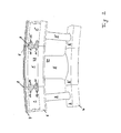
- the single ones Elements consist of an outer platform 1, respectively. 1 'and an inner platform 2, resp. 2 ', between which the blades 2, respectively. 2 'extend. If the Elements are connected to a whole wreath, form the outer platforms 1 in essentially cylindrical outer shroud, which limits the gas flow to the outside. Similarly, the inner platforms 2 form an inner shroud, which limits the gas flow radially inwards. Hot operating gas emerges laterally when the turbine is running limited or directed by the blades 2, 2 'and radially through the inner Shroud, and out through the outer shroud to the actual turbine blade wheel. Most is on the cooling gas sides 23 facing away from the airfoil Provided cooling platforms, i.e. the platforms are powered by a stream of cooling gas applied.
- the cover strips are attached to the turbine housing via ribs 4-7 and, if necessary, also attached.
- the individual elements point to each adjoining edge on a flange 8 which is coherent with the flange 8 of the neighboring element.
- the flange 8 has two in the cooling air area the cooling gas sides 23 projecting extensions 9, in which in holes 14 over Screws 10, 11 and nuts 12, 13, or the elements are riveted together can be connected.
- the connection can also be made by welding or brazing extensions 9 may even be unnecessary.
- An identical one Connection can be made on the lower, invisible side of the inner shroud the inner platforms 2, 2 'are provided.
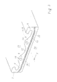
- Fig. 2 shows a triplet of guide vane elements, in each of which differently designed Adjacent elements.
- the middle vane blade 3 ' is much wider designed as the two outer 3 and 3 ".
- the figure is intended to show that the fastening mechanisms not only for pairs or entire rings of identical guide vane elements Can be used, but also in pairs, groups or rings with elements different design and dimensions.
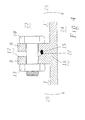
- Fig. 3 shows a view of a flange 8 according to the prior art.
- the Flange two extensions 9 on the cooling gas side 23, in which holes 14 are provided are in which fasteners 10-13 can be inserted.
- a seal 15 is often attached in the edge to one Prevent exchange of gases through the shrouds.
- the seal 15 runs essentially parallel to the platform and over the entire length of the element.
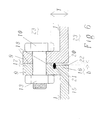
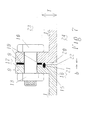
- Fig. 4 is a section along the line A - A of Fig. 3 by connecting two such Flanges are shown in their condition at operating temperature.
- the two elements are by means of a screw 10 and a nut 13 connected.
- In operation there is on the operating gas side a high temperature and a relatively low temperature on the cooling gas side 23.
- the flange i.e. perpendicular to a temperature gradient defined by the platform, which in turn is a differential Material behavior entails.
- the element material in the process gas side expands Hot zone 16, while it is in the cold gas side cold zone 17th barely changed. This has the consequence that a firmly and coherently connected in the cold state Flange 8 warps, and a situation arises as in Fig.
- Fig. 5 now shows an embodiment of a flange in which the above effects be avoided.
- the flange 8 has projections 18 in the area 9 of the fastenings, which protrude over the edge in the direction of the adjacent element.
- the tabs are designed here as rings around the holes 14 in the extensions 9, they can but also extend on the cooling gas side of the seal 15 over the entire length of the element, or in the form of bands or bases.
- a cut at low temperature along line A - A in FIG. 5 of two connected elements is shown in FIG. 6. It shows how the projection 18 extends in front of the edge 22 by the width b in the cold state extends.
- the projection 18 is on the cooling gas side above the recessed in a recess 21 Seal 15 arranged, and in the direction of the operating gas side 24 remains between the platforms 1 and 1 'a column 20.
- the seal 15 ensures that even at low temperature of the elements (as shown), i.e. if the differential temperature behavior has not yet set along the flange 8, a dense, and gas exchange preventing connection between the elements is guaranteed. Now stretches the area 16 as a result of heating the operating gas side 24, this does not lead to the construction a tension in the flange, but only that the column 20 narrows.
- a column 20 can be formed in a wide variety of ways. On the one hand it is possible with a guide vane element according to the prior art in a post-processing step to mill down the edge plane in the area on the cooling gas side, leaving it the projections 18. This can only be done in one of the contiguous Platforms occur, as shown in FIG. 6, but it can also prove to be advantageous to provide a projection that is about half as high in both edges, so that at operating temperature occurring distortions in the connection can be balanced symmetrically can.
- the column can also be formed by simply between the two platforms 1 and 1 'for the extensions 9, a washer 19 or an equivalent, spacing Means is introduced.
- This embodiment is in Fig. 7 in a section cold temperature.
- the advantage of this solution is not only the simplicity, but also also the fact that the column 20 is so modifiable at different operating temperatures can be adjusted.
- the choice of a washer of thickness b determines so the dimensioning of column 20.
- Disc material can also be chosen from a material that is different from that of the elements is different. So it is also conceivable to use special metal alloys as disk material, To use plastics or ceramics, their temperature and tensile, torsional and Tension behavior of the task can be optimally adjusted.
Landscapes
- Engineering & Computer Science (AREA)
- Mechanical Engineering (AREA)
- General Engineering & Computer Science (AREA)
- Turbine Rotor Nozzle Sealing (AREA)
Abstract
Description
- Fig. 1
- ein Paar von mittels Schraubverbindungen aneinander befestigten Leitschaufelelementen in einer perspektivischen Ansicht;
- Fig. 2
- ein Triplett von mittels Schraubverbindungen aneinander befestigten Elementen, wobei verschiedene Elemente nebeneinander zu liegen kommen;
- Fig. 3
- die Kante einer Plattform eines Leitschaufelelementes nach dem Stand der Technik in perspektivischer Ansicht;
- Fig. 4
- einen Schnitt gem. A--A in Fig. 3 durch den Verbindungsbereich eines Paares von Plattformen nach dem Stand der Technik in ihrem Zustand bei Betriebstemperatur;
- Fig. 5
- die Kante einer Plattform eines Leitschaufelelementes in perspektivischer Ansicht;
- Fig. 6
- einen Schnitt gem. A--A in Fig. 5 durch den Verbindungsbereich eines Paares von Plattformen in ihrem kalten Zustand wobei die Kränze als Vorsprünge ausgebildet sind; und
- Fig. 7
- einen Schnitt gem. A--A in Fig. 5 durch den Verbindungsbereich eines Paares von Plattformen in ihrem kalten Zustand wobei die Kränze als Unterlagsscheiben ausgebildet sind.
- 1
- äussere Plattform
- 2
- innere Plattform
- 3
- Schaufelblatt
- 4-7
- Rippen
- 8
- Flansch
- 9
- Erweiterung des Flansches
- 10,11
- Schraube
- 12,13
- Mutter
- 14
- Bohrung in 9
- 15
- Dichtung
- 16
- Heisszone
- 17
- Kaltzone
- 18
- Vorsprung um 14
- 19
- Unterlagsscheibe um 14
- 20
- Spalte
- 21
- Aussparung für 15
- 22
- Kante
- 23
- Kühlgasseite
- 24
- Betriebsgasseite
- 25
- Biegemoment
Claims (10)
- Leitschaufelelement für eine Gasturbine mit einem Schaufelblatt (3), das sich zwischen einer bezüglich der Hauptachse der Gasturbine radial inneren Plattform (1) und einer radial äusseren Plattform (2) erstreckt, wobei an wenigstens einer, in Umfangsrichtung bezüglich der Hauptachse an ein benachbartes zweites Leitschaufelelement angrenzenden Kante (22) der Plattformen (1,2), auf der dem Schaufelblatt (3) abgewandten Seite der Plattform (1,2) ein Flansch (8) vorgesehen ist, über welchen Flansch (8) das zweite Leitschaufelelement über einen am zweiten Leitschaufelelement angeordneten zweiten Flansch (8'), welcher an einer am zweiten Leitschaufelelement vorgesehenen zweiten Plattform (1',2') vorgesehen ist, am ersten Leitschaufelelement unter ein Deckband bildender Verbindung der Plattformen (1,2;1',2') befestigt werden kann,
dadurch gekennzeichnet, dass
erste Mittel (18,19) vorgesehen sind, welche beim Befestigen zweier benachbarter Plattformen aneinander im dem Schaufelblatt (3) abgewandten, und die Befestigungsmittel (10-13) aufweisenden Bereich (17) eine schlüssig an den benachbarten Flansch (8') anliegende Verbindung erlauben, während im dem Schaufelblatt (3) und den Betriebsgasen zugewandten Bereich zwischen den benachbarten Plattformen (1,2;1',2') bei gleichverteilter sowie bei hoher Temperatur eine Spalte (20) verbleibt. - Leitschaufelelement nach Anspruch 1, dadurch gekennzeichnet, dass zweite Mittel (15) vorgesehen sind, welche einen Austausch von Luft zwischen der dem Schaufelblatt (3) zugewandten Seite (24) der Plattform (1,2;1',2') resp. des Deckbandes zur dem Schaufelblatt abgewandten Seite (23) des Deckbandes verhindern.
- Leitschaufelelement nach Anspruch 2, dadurch gekennzeichnet, dass die zweiten Mittel als in der Spalte (20) und bezüglich der ersten Mittel (18,19) schaufelblattseitig verlaufende, insbesondere bevorzugt in einer Aussparung (21) angeordnete Dichtungen (15) ausgebildet sind.
- Leitschaufelelement nach einem der Ansprüche 1 bis 3, dadurch gekennzeichnet, dass die ersten Mittel als im Bereich der Befestigungsmittel (10-13) angeordnete, in Richtung des zweiten Leitschaufelelementes über die Kante (22) hinausragende Kränze (18,19) ausgebildet sind, und dass die schlüssige Verbindung mit dem zweiten Leitschaufelelement über die Kränze (18,19) erfolgt.
- Leitschaufelelement nach einem der Ansprüche 1 bis 4, dadurch gekennzeichnet, dass die Kränze als aus dem Flansch (8), insbesondere im Bereich einer für die Befestigungsmittel (10-13) vorgesehenen Erweiterung (9) des Flansches freigefräste Vorsprünge (18) gestaltet sind.
- Leitschaufelelement nach einem der Ansprüche 1 bis 4, dadurch gekennzeichnet, dass die Kränze als Unterlagsscheiben (19) gestaltet sind.
- Leitschaufelelement nach einem der Ansprüche 1 bis 6, dadurch gekennzeichnet, dass die Befestigungsmittel (10-13) aus Schrauben-Mutter Verbindungen, Nietverbindungen, geschweissten oder hartgelöteten Verbindungen bestehen.
- Leitschaufelelement nach einem der Ansprüche 1 bis 7, dadurch gekennzeichnet, dass die ersten Mittel (18,19) an der äusseren (1) und der inneren (2) Plattform vorgesehen sind, und dass weiterhin bevorzugt die ersten Mittel (18,19) beidseitig, d.h. auch in Richtung eines dritten, auf einer zweiten Seite benachbarten Leitschaufelelementes vorgesehen sind.
- Leitschaufelelement nach einem der Ansprüche 1 bis 8, dadurch gekennzeichnet, dass es sich bei den benachbarten Leitschaufelelementen um Elemente mit unterschiedlichen Schaufelblättern handelt.
- Leitschaufelelement nach einem der Ansprüche 1 bis 9, dadurch gekennzeichnet, dass die Spalte (20) Kaltzustand auf der dem Schaufelblatt (3) zugewandten Seite eine Breite (b) von 0.5 bis 1.0 mm aufweist, und dass die Spalte (20) eine Tiefe (T) von 10 bis 30 mm, aufweist.
Applications Claiming Priority (2)
| Application Number | Priority Date | Filing Date | Title |
|---|---|---|---|
| DE10051223A DE10051223A1 (de) | 2000-10-16 | 2000-10-16 | Verbindbare Statorelemente |
| DE10051223 | 2000-10-16 |
Publications (3)
| Publication Number | Publication Date |
|---|---|
| EP1199440A2 true EP1199440A2 (de) | 2002-04-24 |
| EP1199440A3 EP1199440A3 (de) | 2004-01-21 |
| EP1199440B1 EP1199440B1 (de) | 2006-11-02 |
Family
ID=7659952
Family Applications (1)
| Application Number | Title | Priority Date | Filing Date |
|---|---|---|---|
| EP01122716A Expired - Lifetime EP1199440B1 (de) | 2000-10-16 | 2001-09-21 | Leitschaufelkranzsegmente mit Flanschverbindung |
Country Status (3)
| Country | Link |
|---|---|
| US (2) | US6592326B2 (de) |
| EP (1) | EP1199440B1 (de) |
| DE (2) | DE10051223A1 (de) |
Cited By (5)
| Publication number | Priority date | Publication date | Assignee | Title |
|---|---|---|---|---|
| WO2008121047A1 (en) * | 2007-03-30 | 2008-10-09 | Volvo Aero Corporation | A gas turbine engine component, a turbojet engine provided therewith, and an aircraft provided therewith |
| WO2010007220A3 (fr) * | 2008-06-25 | 2010-03-11 | Snecma | Carter structural pour turbomachine |
| WO2010089125A3 (de) * | 2009-02-07 | 2011-06-16 | Hobis Ag | Leitringelement für turbinen und verfahren zu dessen herstellung |
| US8371810B2 (en) | 2009-03-26 | 2013-02-12 | General Electric Company | Duct member based nozzle for turbine |
| CN109153094A (zh) * | 2016-05-26 | 2019-01-04 | 赛峰飞机发动机公司 | 用于由焊接在一起的部段制造涡轮机排气壳体的方法 |
Families Citing this family (23)
| Publication number | Priority date | Publication date | Assignee | Title |
|---|---|---|---|---|
| GB2388161A (en) * | 2002-05-02 | 2003-11-05 | Rolls Royce Plc | Gas turbine engine compressor casing |
| US7101150B2 (en) * | 2004-05-11 | 2006-09-05 | Power Systems Mfg, Llc | Fastened vane assembly |
| JP4918263B2 (ja) * | 2006-01-27 | 2012-04-18 | 三菱重工業株式会社 | 軸流圧縮機の静翼環 |
| US8950069B2 (en) * | 2006-12-29 | 2015-02-10 | Rolls-Royce North American Technologies, Inc. | Integrated compressor vane casing |
| US7837435B2 (en) * | 2007-05-04 | 2010-11-23 | Power System Mfg., Llc | Stator damper shim |
| US8202043B2 (en) * | 2007-10-15 | 2012-06-19 | United Technologies Corp. | Gas turbine engines and related systems involving variable vanes |
| US8511982B2 (en) * | 2008-11-24 | 2013-08-20 | Alstom Technology Ltd. | Compressor vane diaphragm |
| GB2468848B (en) * | 2009-03-23 | 2011-10-26 | Rolls Royce Plc | An assembly for a turbomachine |
| US8356975B2 (en) * | 2010-03-23 | 2013-01-22 | United Technologies Corporation | Gas turbine engine with non-axisymmetric surface contoured vane platform |
| US8360716B2 (en) * | 2010-03-23 | 2013-01-29 | United Technologies Corporation | Nozzle segment with reduced weight flange |
| US9976433B2 (en) | 2010-04-02 | 2018-05-22 | United Technologies Corporation | Gas turbine engine with non-axisymmetric surface contoured rotor blade platform |
| US9303531B2 (en) | 2011-12-09 | 2016-04-05 | General Electric Company | Quick engine change assembly for outlet guide vanes |
| US9303520B2 (en) * | 2011-12-09 | 2016-04-05 | General Electric Company | Double fan outlet guide vane with structural platforms |
| US9127568B2 (en) * | 2012-01-04 | 2015-09-08 | General Electric Company | Turbine casing |
| US10036276B2 (en) * | 2012-06-15 | 2018-07-31 | United Technologies Corporation | High durability turbine exhaust case |
| US20140314547A1 (en) * | 2012-08-31 | 2014-10-23 | United Technologies Corporation | Attachment apparatus for ceramic matrix composite materials |
| US20140248146A1 (en) * | 2012-08-31 | 2014-09-04 | United Technologies Corporation | Attachment apparatus for ceramic matrix composite materials |
| US10364690B2 (en) | 2013-02-22 | 2019-07-30 | United Technologies Corporation | Stator vane assembly and method therefor |
| WO2015023324A2 (en) * | 2013-04-12 | 2015-02-19 | United Technologies Corporation | Stator vane platform with flanges |
| US9506362B2 (en) | 2013-11-20 | 2016-11-29 | General Electric Company | Steam turbine nozzle segment having transitional interface, and nozzle assembly and steam turbine including such nozzle segment |
| US10724390B2 (en) | 2018-03-16 | 2020-07-28 | General Electric Company | Collar support assembly for airfoils |
| JP2022183695A (ja) * | 2021-05-31 | 2022-12-13 | 三菱重工業株式会社 | 静翼セグメント、ガスタービン、及び静翼セグメントの製造方法 |
| US11655758B1 (en) * | 2022-03-31 | 2023-05-23 | Raytheon Technologies Corporation | CMC vane mate face flanges with through-ply seal slots |
Citations (3)
| Publication number | Priority date | Publication date | Assignee | Title |
|---|---|---|---|---|
| US4015910A (en) | 1976-03-09 | 1977-04-05 | The United States Of America As Represented By The Secretary Of The Air Force | Bolted paired vanes for turbine |
| EP0903467A2 (de) | 1997-09-17 | 1999-03-24 | Mitsubishi Heavy Industries, Ltd. | Leitschaufelpaar |
| EP0949404A1 (de) | 1997-01-10 | 1999-10-13 | Mitsubishi Heavy Industries, Ltd. | Leitgitter, das aus einzelnen Leitschaufeln zusammengeschraubt ist |
Family Cites Families (62)
| Publication number | Priority date | Publication date | Assignee | Title |
|---|---|---|---|---|
| US4063849A (en) | 1975-02-12 | 1977-12-20 | Modianos Doan D | Non-clogging, centrifugal, coaxial discharge pump |
| GB1501916A (en) | 1975-06-20 | 1978-02-22 | Rolls Royce | Matching thermal expansions of components of turbo-machines |
| US4000955A (en) | 1975-09-22 | 1977-01-04 | Kiyoshi Tokutomi | Fan with wide curved blades |
| US3975114A (en) | 1975-09-23 | 1976-08-17 | Westinghouse Electric Corporation | Seal arrangement for turbine diaphragms and the like |
| US4021135A (en) | 1975-10-09 | 1977-05-03 | Pedersen Nicholas F | Wind turbine |
| US4204810A (en) | 1976-11-03 | 1980-05-27 | Tokheim Corporation | Bi-directional pump |
| US4309145A (en) | 1978-10-30 | 1982-01-05 | General Electric Company | Cooling air seal |
| US4240990A (en) | 1979-04-10 | 1980-12-23 | Aeration Industries, Inc. | Aeration propeller and apparatus |
| US4576549A (en) | 1980-07-03 | 1986-03-18 | Garden City Fan & Blower Co. | Vortex generator for centrifugal fans |
| US4365929A (en) | 1981-01-16 | 1982-12-28 | Philip Retz | Vertical wind turbine power generating tower |
| US4492517A (en) * | 1983-01-06 | 1985-01-08 | General Electric Company | Segmented inlet nozzle for gas turbine, and methods of installation |
| DE3315350C2 (de) | 1983-04-28 | 1985-10-03 | Klein, Schanzlin & Becker Ag, 6710 Frankenthal | Leitrad für Kreiselpumpen |
| EP0131736B1 (de) | 1983-06-29 | 1987-01-21 | BBC Brown Boveri AG | Axialturbine für Abgasturbolader |
| US4576548A (en) | 1984-01-17 | 1986-03-18 | Westinghouse Electric Corp. | Self-aligning static seal for gas turbine stator vanes |
| US4606699A (en) | 1984-02-06 | 1986-08-19 | General Electric Company | Compressor casing recess |
| US4594761A (en) | 1984-02-13 | 1986-06-17 | General Electric Company | Method of fabricating hollow composite airfoils |
| US4679990A (en) | 1984-12-28 | 1987-07-14 | Matsushita Electric Industrial Co., Ltd. | Electric blower |
| US4686376A (en) | 1986-07-22 | 1987-08-11 | Philip Retz | Tide turbine |
| CH672004A5 (de) | 1986-09-26 | 1989-10-13 | Bbc Brown Boveri & Cie | |
| FR2616889B1 (fr) | 1987-06-18 | 1992-07-31 | Snecma | Carter de chambre de combustion de turboreacteur comportant des orifices de prelevement d'air |
| US4907946A (en) | 1988-08-10 | 1990-03-13 | General Electric Company | Resiliently mounted outlet guide vane |
| US4957412A (en) | 1988-09-06 | 1990-09-18 | Westinghouse Electric Corp. | Apparatus and method for supporting the torque load on a gas turbine vane |
| JPH07101141B2 (ja) | 1989-03-14 | 1995-11-01 | シャープ株式会社 | 冷蔵庫用送風装置 |
| US5253472A (en) | 1990-02-28 | 1993-10-19 | Dev Sudarshan P | Small gas turbine having enhanced fuel economy |
| US5115642A (en) | 1991-01-07 | 1992-05-26 | United Technologies Corporation | Gas turbine engine case with intergral shroud support ribs |
| US5149248A (en) | 1991-01-10 | 1992-09-22 | Westinghouse Electric Corp. | Apparatus and method for adapting an enlarged flow guide to an existing steam turbine |
| US5066194A (en) | 1991-02-11 | 1991-11-19 | Carrier Corporation | Fan orifice structure and cover for outside enclosure of an air conditioning system |
| US5209634A (en) | 1991-02-20 | 1993-05-11 | Owczarek Jerzy A | Adjustable guide vane assembly for the exhaust flow passage of a steam turbine |
| US5161947A (en) | 1991-05-08 | 1992-11-10 | United Technologies Corporation | Fan case strut for turbomachine |
| JP3390989B2 (ja) | 1991-08-30 | 2003-03-31 | エアフロー リサーチ アンド マニュファクチャリング コーポレーション | レーク及び翼弦方向キャンバーが補正された前方スキューファン |
| US5141395A (en) * | 1991-09-05 | 1992-08-25 | General Electric Company | Flow activated flowpath liner seal |
| US5244347A (en) | 1991-10-11 | 1993-09-14 | Siemens Automotive Limited | High efficiency, low noise, axial flow fan |
| US5249921A (en) | 1991-12-23 | 1993-10-05 | General Electric Company | Compressor outlet guide vane support |
| JP3437597B2 (ja) | 1992-03-04 | 2003-08-18 | ラツィオナル アクチエンゲゼルシャフト | ガス成分除去装置 |
| DE69304770T2 (de) | 1992-04-14 | 1997-05-07 | Ebara Corp | Pumpengehäuse in Blechbauweise |
| KR950008058B1 (ko) | 1992-07-24 | 1995-07-24 | 한라공조주식회사 | 팬과 쉬라우드 조립체 |
| DE4232385A1 (de) | 1992-09-26 | 1994-03-31 | Asea Brown Boveri | Gasturbine mit angeflanschtem Abgasgehäuse |
| JP3232844B2 (ja) | 1993-03-29 | 2001-11-26 | 株式会社デンソー | 送風装置 |
| JP3110205B2 (ja) | 1993-04-28 | 2000-11-20 | 株式会社日立製作所 | 遠心圧縮機及び羽根付ディフューザ |
| JP2906939B2 (ja) | 1993-09-20 | 1999-06-21 | 株式会社日立製作所 | 軸流圧縮機 |
| US5441385A (en) * | 1993-12-13 | 1995-08-15 | Solar Turbines Incorporated | Turbine nozzle/nozzle support structure |
| US5454690A (en) | 1994-01-13 | 1995-10-03 | Shop Vac Corporation | Air flow housing |
| JPH09510527A (ja) | 1994-03-19 | 1997-10-21 | カーエスベー・アクチエンゲゼルシャフト | 回転子形ポンプの雑音低減装置 |
| GB2291130B (en) | 1994-07-12 | 1998-09-30 | Rolls Royce Plc | A gas turbine engine |
| FR2728015B1 (fr) * | 1994-12-07 | 1997-01-17 | Snecma | Distributeur monobloc sectorise d'un stator de turbine de turbomachine |
| JP3188128B2 (ja) | 1995-02-21 | 2001-07-16 | 株式会社豊田中央研究所 | 車輌用トルクコンバータのステータ |
| US5772401A (en) | 1995-10-13 | 1998-06-30 | Dresser-Rand Company | Diaphragm construction for turbomachinery |
| DE19547653C2 (de) | 1995-12-20 | 1999-08-19 | Abb Patent Gmbh | Leitvorrichtung für eine Turbine mit einem Leitschaufelträger und Verfahren zur Herstellung dieser Leitvorrichtung |
| US5749702A (en) | 1996-10-15 | 1998-05-12 | Air Handling Engineering Ltd. | Fan for air handling system |
| JPH10205497A (ja) | 1996-11-21 | 1998-08-04 | Zexel Corp | 冷却空気導入排出装置 |
| DE19753373A1 (de) | 1996-12-10 | 1998-06-25 | Papst Motoren Gmbh & Co Kg | Axiallüfter-Gehäuse |
| CA2231986A1 (en) * | 1997-01-10 | 1999-09-12 | Masahito Kataoka | Stationary blade of integrated segment construction and manufacturing method therefor |
| JP3794098B2 (ja) | 1997-01-31 | 2006-07-05 | 株式会社デンソー | 遠心送風機 |
| DE19703033A1 (de) | 1997-01-29 | 1998-07-30 | Asea Brown Boveri | Abgasturbine eines Turboladers |
| JP3604110B2 (ja) | 1997-04-25 | 2004-12-22 | 株式会社エクセディ | トルクコンバータのステータ |
| EP0916812B1 (de) | 1997-11-17 | 2003-03-05 | ALSTOM (Switzerland) Ltd | Endstufe für axialdurchströmte Turbine |
| JP3500292B2 (ja) | 1998-01-30 | 2004-02-23 | 日本電産コパル株式会社 | 軸流ファン |
| GB9805030D0 (en) | 1998-03-11 | 1998-05-06 | Rolls Royce Plc | A stator vane assembly for a turbomachine |
| US6092988A (en) | 1998-07-06 | 2000-07-25 | Ford Motor Company | Centrifugal blower assembly with a pre-swirler for an automotive vehicle |
| US6077032A (en) | 1998-07-16 | 2000-06-20 | Felchar Manufacturing Corporation | Housing assembly for a vacuum cleaner |
| US6077036A (en) | 1998-08-20 | 2000-06-20 | General Electric Company | Bowed nozzle vane with selective TBC |
| US6109868A (en) | 1998-12-07 | 2000-08-29 | General Electric Company | Reduced-length high flow interstage air extraction |
-
2000
- 2000-10-16 DE DE10051223A patent/DE10051223A1/de not_active Withdrawn
-
2001
- 2001-09-21 EP EP01122716A patent/EP1199440B1/de not_active Expired - Lifetime
- 2001-09-21 DE DE50111350T patent/DE50111350D1/de not_active Expired - Lifetime
- 2001-10-16 US US09/977,195 patent/US6592326B2/en not_active Ceased
-
2005
- 2005-07-14 US US11/181,003 patent/USRE43611E1/en not_active Expired - Lifetime
Patent Citations (3)
| Publication number | Priority date | Publication date | Assignee | Title |
|---|---|---|---|---|
| US4015910A (en) | 1976-03-09 | 1977-04-05 | The United States Of America As Represented By The Secretary Of The Air Force | Bolted paired vanes for turbine |
| EP0949404A1 (de) | 1997-01-10 | 1999-10-13 | Mitsubishi Heavy Industries, Ltd. | Leitgitter, das aus einzelnen Leitschaufeln zusammengeschraubt ist |
| EP0903467A2 (de) | 1997-09-17 | 1999-03-24 | Mitsubishi Heavy Industries, Ltd. | Leitschaufelpaar |
Cited By (7)
| Publication number | Priority date | Publication date | Assignee | Title |
|---|---|---|---|---|
| WO2008121047A1 (en) * | 2007-03-30 | 2008-10-09 | Volvo Aero Corporation | A gas turbine engine component, a turbojet engine provided therewith, and an aircraft provided therewith |
| US8459942B2 (en) | 2007-03-30 | 2013-06-11 | Volvo Aero Corporation | Gas turbine engine component, a turbojet engine provided therewith, and an aircraft provided therewith |
| WO2010007220A3 (fr) * | 2008-06-25 | 2010-03-11 | Snecma | Carter structural pour turbomachine |
| US8646744B2 (en) | 2008-06-25 | 2014-02-11 | Snecma | Structural frame for a turbomachine |
| WO2010089125A3 (de) * | 2009-02-07 | 2011-06-16 | Hobis Ag | Leitringelement für turbinen und verfahren zu dessen herstellung |
| US8371810B2 (en) | 2009-03-26 | 2013-02-12 | General Electric Company | Duct member based nozzle for turbine |
| CN109153094A (zh) * | 2016-05-26 | 2019-01-04 | 赛峰飞机发动机公司 | 用于由焊接在一起的部段制造涡轮机排气壳体的方法 |
Also Published As
| Publication number | Publication date |
|---|---|
| EP1199440B1 (de) | 2006-11-02 |
| US20020044868A1 (en) | 2002-04-18 |
| US6592326B2 (en) | 2003-07-15 |
| USRE43611E1 (en) | 2012-08-28 |
| DE10051223A1 (de) | 2002-04-25 |
| DE50111350D1 (de) | 2006-12-14 |
| EP1199440A3 (de) | 2004-01-21 |
Similar Documents
| Publication | Publication Date | Title |
|---|---|---|
| EP1199440B1 (de) | Leitschaufelkranzsegmente mit Flanschverbindung | |
| DE69410195T2 (de) | Leitschaufel mit verstärkter Lötverbindung | |
| EP2307670B1 (de) | Integral beschaufelte rotorscheibe für eine turbine | |
| DE69431540T2 (de) | Abdichtung für Gasturbinen | |
| DE3510230C2 (de) | Brennkammer für ein Gasturbinentriebwerk | |
| EP2927594B1 (de) | Brennkammer einer Gasturbine | |
| DE2908242C2 (de) | Rindförmiger Flansch für den Läufer einer axial durchströmten Strömungsmaschine zum Zusammenwirken mit einer Stirnfläche eines Radkranzes oder dergleichen | |
| DE1953047A1 (de) | Gas- oder Dampfturbine der Axialbauart fuer hohe Arbeitsmitteltemperaturen | |
| EP3409897B1 (de) | Dichtungsanordnung für eine strömungsmaschine, verfahren zur herstellung einer dichtungsanordnung sowie strömungsmaschine | |
| DE1953790A1 (de) | Gasturbine der Axialbauart | |
| EP2132414B1 (de) | Shiplap-anordnung | |
| EP1451450B1 (de) | Gasturbogruppe | |
| DE3446389A1 (de) | Statoraufbau fuer ein gasturbinen-triebwerk | |
| DE2258618A1 (de) | Bolzenloser blatt- und dichtungshalter | |
| CH642428A5 (de) | Abdeckanordnung in einer turbine. | |
| DE102012008723A1 (de) | Leitrad für Turbomaschinen und Herstellungsverfahren | |
| EP1653049B1 (de) | Leitschaufelring einer Strömungsmaschine und zugehöriges Modifikationsverfahren | |
| EP2342425B1 (de) | Gasturbine mit sicherungsplatte zwischen schaufelfuss und scheibe | |
| DE69812837T2 (de) | Doppelkreuzdichtung für Gasturbinenleitschaufeln | |
| DE60115377T2 (de) | Leitschaufelanordnung für eine Axialturbine | |
| DE4006498C2 (de) | Vorrichtung zum Abdichten eines Raumes in einer Turbomaschine | |
| EP2428647B1 (de) | Übergangsbereich für eine Brennkammer einer Gasturbine | |
| DE2711564A1 (de) | Brennerhalterungsvorrichtung | |
| DE2032505A1 (de) | Gekühlte Turbinenlaufschaufel | |
| EP1960636B1 (de) | Strömungsmaschine |
Legal Events
| Date | Code | Title | Description |
|---|---|---|---|
| PUAI | Public reference made under article 153(3) epc to a published international application that has entered the european phase |
Free format text: ORIGINAL CODE: 0009012 |
|
| AK | Designated contracting states |
Kind code of ref document: A2 Designated state(s): AT BE CH CY DE DK ES FI FR GB GR IE IT LI LU MC NL PT SE TR |
|
| AX | Request for extension of the european patent |
Free format text: AL;LT;LV;MK;RO;SI |
|
| PUAL | Search report despatched |
Free format text: ORIGINAL CODE: 0009013 |
|
| AK | Designated contracting states |
Kind code of ref document: A3 Designated state(s): AT BE CH CY DE DK ES FI FR GB GR IE IT LI LU MC NL PT SE TR |
|
| AX | Request for extension of the european patent |
Extension state: AL LT LV MK RO SI |
|
| RIC1 | Information provided on ipc code assigned before grant |
Ipc: 7F 01D 9/04 A Ipc: 7F 01D 11/00 B |
|
| RAP1 | Party data changed (applicant data changed or rights of an application transferred) |
Owner name: ALSTOM TECHNOLOGY LTD |
|
| 17P | Request for examination filed |
Effective date: 20040710 |
|
| AKX | Designation fees paid |
Designated state(s): DE GB |
|
| GRAP | Despatch of communication of intention to grant a patent |
Free format text: ORIGINAL CODE: EPIDOSNIGR1 |
|
| GRAS | Grant fee paid |
Free format text: ORIGINAL CODE: EPIDOSNIGR3 |
|
| GRAA | (expected) grant |
Free format text: ORIGINAL CODE: 0009210 |
|
| AK | Designated contracting states |
Kind code of ref document: B1 Designated state(s): DE GB |
|
| REG | Reference to a national code |
Ref country code: GB Ref legal event code: FG4D Free format text: NOT ENGLISH |
|
| REF | Corresponds to: |
Ref document number: 50111350 Country of ref document: DE Date of ref document: 20061214 Kind code of ref document: P |
|
| GBT | Gb: translation of ep patent filed (gb section 77(6)(a)/1977) |
Effective date: 20061213 |
|
| PLBE | No opposition filed within time limit |
Free format text: ORIGINAL CODE: 0009261 |
|
| STAA | Information on the status of an ep patent application or granted ep patent |
Free format text: STATUS: NO OPPOSITION FILED WITHIN TIME LIMIT |
|
| 26N | No opposition filed |
Effective date: 20070803 |
|
| REG | Reference to a national code |
Ref country code: DE Ref legal event code: R082 Ref document number: 50111350 Country of ref document: DE Representative=s name: ROESLER, UWE, DIPL.-PHYS.UNIV., DE Ref country code: DE Ref legal event code: R081 Ref document number: 50111350 Country of ref document: DE Owner name: GENERAL ELECTRIC TECHNOLOGY GMBH, CH Free format text: FORMER OWNER: ALSTOM TECHNOLOGY LTD., BADEN, CH Ref country code: DE Ref legal event code: R081 Ref document number: 50111350 Country of ref document: DE Owner name: ANSALDO ENERGIA IP UK LIMITED, GB Free format text: FORMER OWNER: ALSTOM TECHNOLOGY LTD., BADEN, CH |
|
| REG | Reference to a national code |
Ref country code: DE Ref legal event code: R082 Ref document number: 50111350 Country of ref document: DE Representative=s name: ROESLER, UWE, DIPL.-PHYS.UNIV., DE Ref country code: DE Ref legal event code: R081 Ref document number: 50111350 Country of ref document: DE Owner name: ANSALDO ENERGIA IP UK LIMITED, GB Free format text: FORMER OWNER: GENERAL ELECTRIC TECHNOLOGY GMBH, BADEN, CH |
|
| REG | Reference to a national code |
Ref country code: GB Ref legal event code: 732E Free format text: REGISTERED BETWEEN 20170824 AND 20170830 |
|
| PGFP | Annual fee paid to national office [announced via postgrant information from national office to epo] |
Ref country code: DE Payment date: 20170928 Year of fee payment: 17 Ref country code: GB Payment date: 20170921 Year of fee payment: 17 |
|
| REG | Reference to a national code |
Ref country code: DE Ref legal event code: R119 Ref document number: 50111350 Country of ref document: DE |
|
| GBPC | Gb: european patent ceased through non-payment of renewal fee |
Effective date: 20180921 |
|
| PG25 | Lapsed in a contracting state [announced via postgrant information from national office to epo] |
Ref country code: DE Free format text: LAPSE BECAUSE OF NON-PAYMENT OF DUE FEES Effective date: 20190402 |
|
| PG25 | Lapsed in a contracting state [announced via postgrant information from national office to epo] |
Ref country code: GB Free format text: LAPSE BECAUSE OF NON-PAYMENT OF DUE FEES Effective date: 20180921 |