US8360716B2 - Nozzle segment with reduced weight flange - Google Patents
Nozzle segment with reduced weight flange Download PDFInfo
- Publication number
- US8360716B2 US8360716B2 US12/730,180 US73018010A US8360716B2 US 8360716 B2 US8360716 B2 US 8360716B2 US 73018010 A US73018010 A US 73018010A US 8360716 B2 US8360716 B2 US 8360716B2
- Authority
- US
- United States
- Prior art keywords
- nozzle segment
- flange
- hollow cavity
- vane platform
- recited
- Prior art date
- Legal status (The legal status is an assumption and is not a legal conclusion. Google has not performed a legal analysis and makes no representation as to the accuracy of the status listed.)
- Active, expires
Links
Images


Classifications
-
- F—MECHANICAL ENGINEERING; LIGHTING; HEATING; WEAPONS; BLASTING
- F01—MACHINES OR ENGINES IN GENERAL; ENGINE PLANTS IN GENERAL; STEAM ENGINES
- F01D—NON-POSITIVE DISPLACEMENT MACHINES OR ENGINES, e.g. STEAM TURBINES
- F01D9/00—Stators
- F01D9/02—Nozzles; Nozzle boxes; Stator blades; Guide conduits, e.g. individual nozzles
-
- F—MECHANICAL ENGINEERING; LIGHTING; HEATING; WEAPONS; BLASTING
- F01—MACHINES OR ENGINES IN GENERAL; ENGINE PLANTS IN GENERAL; STEAM ENGINES
- F01D—NON-POSITIVE DISPLACEMENT MACHINES OR ENGINES, e.g. STEAM TURBINES
- F01D11/00—Preventing or minimising internal leakage of working-fluid, e.g. between stages
- F01D11/005—Sealing means between non relatively rotating elements
-
- F—MECHANICAL ENGINEERING; LIGHTING; HEATING; WEAPONS; BLASTING
- F05—INDEXING SCHEMES RELATING TO ENGINES OR PUMPS IN VARIOUS SUBCLASSES OF CLASSES F01-F04
- F05D—INDEXING SCHEME FOR ASPECTS RELATING TO NON-POSITIVE-DISPLACEMENT MACHINES OR ENGINES, GAS-TURBINES OR JET-PROPULSION PLANTS
- F05D2240/00—Components
- F05D2240/10—Stators
- F05D2240/12—Fluid guiding means, e.g. vanes
- F05D2240/128—Nozzles
-
- F—MECHANICAL ENGINEERING; LIGHTING; HEATING; WEAPONS; BLASTING
- F05—INDEXING SCHEMES RELATING TO ENGINES OR PUMPS IN VARIOUS SUBCLASSES OF CLASSES F01-F04
- F05D—INDEXING SCHEME FOR ASPECTS RELATING TO NON-POSITIVE-DISPLACEMENT MACHINES OR ENGINES, GAS-TURBINES OR JET-PROPULSION PLANTS
- F05D2240/00—Components
- F05D2240/80—Platforms for stationary or moving blades
-
- Y—GENERAL TAGGING OF NEW TECHNOLOGICAL DEVELOPMENTS; GENERAL TAGGING OF CROSS-SECTIONAL TECHNOLOGIES SPANNING OVER SEVERAL SECTIONS OF THE IPC; TECHNICAL SUBJECTS COVERED BY FORMER USPC CROSS-REFERENCE ART COLLECTIONS [XRACs] AND DIGESTS
- Y02—TECHNOLOGIES OR APPLICATIONS FOR MITIGATION OR ADAPTATION AGAINST CLIMATE CHANGE
- Y02T—CLIMATE CHANGE MITIGATION TECHNOLOGIES RELATED TO TRANSPORTATION
- Y02T50/00—Aeronautics or air transport
- Y02T50/60—Efficient propulsion technologies, e.g. for aircraft
Definitions
- the present disclosure relates to a gas turbine engine turbine section, and more particularly to a reduced weight nozzle segment.
- the core engine of a gas turbine engine typically includes a multistage axial compressor, a combustor and a high pressure turbine nozzle with one or more stages.
- Typical turbine nozzles such as high pressure and low pressure turbine nozzles, define annular rings located adjacent to each turbine blade row.
- a nozzle segment for a gas turbine engine includes a flange which extends from a vane platform, the flange includes a hollow cavity.
- a nozzle segment for a gas turbine engine includes a turbine vane which extends between an outer vane platform and an inner vane platform.
- a flange extends from the outer vane platform, the flange includes a hollow cavity.
- FIG. 1 is a general perspective view an exemplary gas turbine engine embodiment for use with the present disclosure
- FIG. 2 is an expanded view of a vane portion of one turbine stage within a turbine section of the gas turbine engine, the vane portion formed from a multiple of turbine nozzle segments;
- FIG. 3 is an expanded schematic sectional view of a turbine section
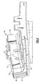
- FIG. 4 is a perspective view of one variable turbine nozzle segment
- FIG. 5 is an expanded partial phantom view of a structural flange according to one non-limiting embodiment for the variable turbine nozzle segment
- FIG. 6 is an expanded partial phantom view of a structural flange according to one non-limiting embodiment for the variable turbine nozzle segment.
- FIG. 7 is a graphical representation of the gap between the structural flange and the associated seal assemblies.
- FIG. 8 shows a cross-sectional view of another non-limiting embodiment of a structural flange having a hollow cavity therein.
- FIG. 9 shows a perspective view of a casting with a hollow cavity.
- FIG. 10 shows a perspective view of the casting of FIG. 9 being machined.
- FIG. 1 illustrates a general schematic view of a gas turbine engine 10 such as a gas turbine engine for propulsion. While a two spool high bypass turbofan engine is schematically illustrated in the disclosed non-limiting embodiment, it should be understood that the disclosure is applicable to other gas turbine engine configurations, including, for example, gas turbines for power generation, turbojet engines, low bypass turbofan engines, turboshaft engines, etc.
- the engine 10 includes a core engine section that houses a low spool 14 and high spool 24 .
- the low spool 14 includes a low pressure compressor 16 and a low pressure turbine 18 .
- the core engine section drives a fan section 20 connected to the low spool 14 either directly or through a gear train.
- the high spool 24 includes a high pressure compressor 26 and high pressure turbine 28 .
- a combustor 30 is arranged between the high pressure compressor 26 and high pressure turbine 28 .
- the low and high spools 14 , 24 rotate about an engine axis of rotation A.
- Air compressed in the compressors 16 , 26 is mixed with fuel, burned in the combustor 30 , and expanded in turbines 18 , 28 .
- the air compressed in the compressors 16 , 26 and the fuel mixture expanded in the turbines 18 , 28 may be referred to as a hot gas stream along a core gas path.
- the turbines 18 , 28 in response to the expansion, drive the compressors 16 , 26 and fan section 20 .
- a nozzle segment 40 includes an arcuate outer vane platform 42 and an arcuate inner vane platform 44 radially spaced apart from each other.
- the arcuate outer vane platform 42 may form a portion of an outer core engine structure 46 and the arcuate inner vane platform 44 may form a portion of an inner core engine structure 48 ( FIG. 3 ) to at least partially define an annular turbine nozzle core gas flow path.
- the circumferentially adjacent vane platforms 42 , 44 thermally uncouple adjacent nozzle segments 40 . That is, the temperature environment of the turbine section 18 and the substantial aerodynamic and thermal loads are accommodated by the plurality of circumferentially adjoining nozzle segments 40 which collectively form a full, annular ring about the centerline axis X of the engine.
- a nozzle segment 40 for a turbine nozzle are illustrated in the disclosed embodiment, it should be understood that other nozzle sections such as compressor nozzle sections may also benefit herefrom.
- Each nozzle segment 40 may include one or more circumferentially spaced turbine vanes 52 which extend radially between the vane platforms 42 , 44 . That is, the full, annular ring formed by the multiple of nozzle segments 40 provide a vane portion of one stage in the turbine section 18 which is defined by the turbine vanes 52 .
- the outer vane platform 42 includes a structural flange 54 which extends in a radial direction.
- the structural flange 54 operates as a forward seal surface 56 for a forward seal assembly 58 and an aft seal surface 60 for an aft seal assembly 62 . ( FIG. 3 ).
- the structural flange 54 also includes one or more featherseal slots 64 within a mate surface 66 to provide a seal between circumferential adjacent nozzle segments 40 .
- the structural flange 54 includes a hollow cavity 68 to reduce the weight thereof without functional effect.
- a relatively thick but partially hollow structural flange 54 is thereby provided which will readily support the axial load applied to the outer vane platform 42 .
- Finite element analysis using ANSYS indicates this feature will not cause high stress areas. In one non-limiting embodiment, 3.5% decrease in weight is provided.
- the hollow cavity 68 may be formed though a lost investment casting process which may utilize a ceramic core to hollow out the structural flange 54 .
- a core print-out 70 may be located to extend through a radial face 72 of the structural flange 54 to facilitate manufacture.
- the hollow cavity 68 may include a multiple of stiffening ribs 74 .
- the multiple of stiffening ribs 74 extend through the hollow cavity 68 between the forward seal surface 56 and the aft seal surface 60 .
- the multiple of stiffening ribs 74 may also extend through an inboard portion 76 of the hollow cavity 68 . It should be understood that various stiffeners may alternatively or additionally be provided.
- a hollow cavity 80 in another non-limiting embodiment includes a multiple of stiffening features 82 such as pedestals, posts, ribs or other such features.
- the multiple of stiffening features 82 may be utilized with or without the multiple of stiffening ribs 74 (two shown) as well as other features.
- the stiffening features 82 may be formed with a ceramic core to optimize weight reduction with sufficient stiffness for a safe natural resonant frequency and bowing prevention of the seal assemblies 58 , 62 as well as chordal seal 63 which is a machine-ground surface such that relative position is of significant criticality.
- thermal differences may tend to cause curl in the structural flange 54 such that the seal assembly 58 , 62 and/or chordal seal 63 may lift from their respective mate face surfaces 56 , 60 and/or 61 which may increase cooling air leakage.
- the cumulative gap decreased by 22% with the stiffening ribs 74 ( FIG. 7 ).
- a hollow cavity 90 in another non-limiting embodiment includes one or more purge openings 92 ( FIGS. 9 and 10 ) in communication with a higher pressure region adjacent to the structural flange 54 which generally separates the higher pressure region from a lower pressure region in combination with the seal assemblies 58 , 62 . That is, the hollow cavity is located and in communication with the otherwise stagnant air between two cavities of different pressures that may already have a metered flow through a metered aperture 94 . The flow from the metered aperture 94 is conventionally utilized so, the one or more purge openings 92 does not result in an overall cooling flow loss.
- the hollow cavity 90 receives air from the higher pressure cavity through the one or more purge openings 92 and expels the air through the core print-out 70 utilized during the casting process.
- the feed and/or exit holes may be created by machining with laser drilling, EDM, or grinding.
- the one or more purge openings 92 may alternatively be cast produced by the casting process from the wax die, core print-outs, or with “pedestals” in the ceramic. ( FIGS. 9 and 10 ). The “pedestals” may not be visible in the casting ( FIG. 9 ), but once the vane flange is machined, the pedestals are thereby opened to form the one or more purge openings 92 ( FIG. 10 ).
- the hollow cavity 90 with the one or more purge openings 92 minimize stagnant air that may otherwise result in oxidation and corrosion. A metered flow already exists between the two cavities, so the purge flow does not lose cooling flow. Multiple methods may be utilized to create the inlet and exit holes. The current application selected uses a pedestal in the ceramic core as the inlet and the core print-out as the exit; this configuration has the lowest recurring cost.
Abstract
Description
Claims (17)
Priority Applications (2)
| Application Number | Priority Date | Filing Date | Title |
|---|---|---|---|
| US12/730,180 US8360716B2 (en) | 2010-03-23 | 2010-03-23 | Nozzle segment with reduced weight flange |
| EP11250269.5A EP2369139B1 (en) | 2010-03-23 | 2011-03-09 | Nozzle segment with reduced weight flange |
Applications Claiming Priority (1)
| Application Number | Priority Date | Filing Date | Title |
|---|---|---|---|
| US12/730,180 US8360716B2 (en) | 2010-03-23 | 2010-03-23 | Nozzle segment with reduced weight flange |
Publications (2)
| Publication Number | Publication Date |
|---|---|
| US20110236199A1 US20110236199A1 (en) | 2011-09-29 |
| US8360716B2 true US8360716B2 (en) | 2013-01-29 |
Family
ID=44278771
Family Applications (1)
| Application Number | Title | Priority Date | Filing Date |
|---|---|---|---|
| US12/730,180 Active 2031-05-26 US8360716B2 (en) | 2010-03-23 | 2010-03-23 | Nozzle segment with reduced weight flange |
Country Status (2)
| Country | Link |
|---|---|
| US (1) | US8360716B2 (en) |
| EP (1) | EP2369139B1 (en) |
Cited By (12)
| Publication number | Priority date | Publication date | Assignee | Title |
|---|---|---|---|---|
| US20110243722A1 (en) * | 2010-03-30 | 2011-10-06 | Murphy Richard M | Anti-rotation slot for turbine vane |
| US20130115065A1 (en) * | 2011-11-06 | 2013-05-09 | General Electric Company | Asymmetric radial spline seal for a gas turbine engine |
| US20160333712A1 (en) * | 2015-05-11 | 2016-11-17 | United Technologies Corporation | Chordal seal |
| US9816387B2 (en) | 2014-09-09 | 2017-11-14 | United Technologies Corporation | Attachment faces for clamped turbine stator of a gas turbine engine |
| US20190078469A1 (en) * | 2017-09-11 | 2019-03-14 | United Technologies Corporation | Fan exit stator assembly retention system |
| US10273819B2 (en) * | 2016-08-25 | 2019-04-30 | United Technologies Corporation | Chamfered stator vane rail |
| US10428668B2 (en) | 2015-11-19 | 2019-10-01 | MTU Aero Engines AG | Vane segment with peripheral securing |
| EP3581294A1 (en) * | 2018-06-11 | 2019-12-18 | United Technologies Corporation | Casting plug with flow control features |
| US10557360B2 (en) * | 2016-10-17 | 2020-02-11 | United Technologies Corporation | Vane intersegment gap sealing arrangement |
| US20200340405A1 (en) * | 2019-04-24 | 2020-10-29 | United Technologies Corporation | Chordal seal |
| US20200340362A1 (en) * | 2019-04-24 | 2020-10-29 | United Technologies Corporation | Vane core assemblies and methods |
| US11248470B2 (en) | 2018-11-09 | 2022-02-15 | Raytheon Technologies Corporation | Airfoil with core cavity that extends into platform shelf |
Families Citing this family (7)
| Publication number | Priority date | Publication date | Assignee | Title |
|---|---|---|---|---|
| US8794640B2 (en) * | 2010-03-25 | 2014-08-05 | United Technologies Corporation | Turbine sealing system |
| US9109453B2 (en) * | 2012-07-02 | 2015-08-18 | United Technologies Corporation | Airfoil cooling arrangement |
| US8707712B2 (en) * | 2012-07-02 | 2014-04-29 | United Technologies Corporation | Gas turbine engine turbine vane airfoil profile |
| US9080452B2 (en) * | 2012-09-28 | 2015-07-14 | United Technologies Corporation | Gas turbine engine airfoil with vane platform cooling passage |
| US9670790B2 (en) * | 2012-09-28 | 2017-06-06 | United Technologies Corporation | Turbine vane with mistake reduction feature |
| GB201612646D0 (en) * | 2016-07-21 | 2016-09-07 | Rolls Royce Plc | An air cooled component for a gas turbine engine |
| US11840930B2 (en) * | 2019-05-17 | 2023-12-12 | Rtx Corporation | Component with feather seal slots for a gas turbine engine |
Citations (31)
| Publication number | Priority date | Publication date | Assignee | Title |
|---|---|---|---|---|
| US3529903A (en) * | 1968-11-29 | 1970-09-22 | Westinghouse Electric Corp | Nozzle blade structure |
| US4132114A (en) | 1977-03-14 | 1979-01-02 | Westinghouse Electric Corp. | Temperature probe assembly for gas turbine engine |
| US4150915A (en) | 1976-12-23 | 1979-04-24 | Caterpillar Tractor Co. | Variable geometry turbine nozzle |
| US4512712A (en) | 1983-08-01 | 1985-04-23 | United Technologies Corporation | Turbine stator assembly |
| US4585390A (en) | 1984-06-04 | 1986-04-29 | General Electric Company | Vane retaining means |
| US4720236A (en) | 1984-12-21 | 1988-01-19 | United Technologies Corporation | Coolable stator assembly for a gas turbine engine |
| US5078576A (en) | 1989-07-06 | 1992-01-07 | Rolls-Royce Plc | Mounting system for engine components having dissimilar coefficients of thermal expansion |
| US5129783A (en) | 1989-09-22 | 1992-07-14 | Rolls-Royce Plc | Gas turbine engines |
| US5149250A (en) | 1991-02-28 | 1992-09-22 | General Electric Company | Gas turbine vane assembly seal and support system |
| US5222360A (en) | 1991-10-30 | 1993-06-29 | General Electric Company | Apparatus for removably attaching a core frame to a vane frame with a stable mid ring |
| US5848874A (en) | 1997-05-13 | 1998-12-15 | United Technologies Corporation | Gas turbine stator vane assembly |
| US6077035A (en) | 1998-03-27 | 2000-06-20 | Pratt & Whitney Canada Corp. | Deflector for controlling entry of cooling air leakage into the gaspath of a gas turbine engine |
| US6155056A (en) | 1998-06-04 | 2000-12-05 | Pratt & Whitney Canada Corp. | Cooling louver for annular gas turbine engine combustion chamber |
| US6179559B1 (en) | 1998-06-19 | 2001-01-30 | Rolls-Royce Plc | Variable camber vane |
| US6216438B1 (en) | 1998-04-04 | 2001-04-17 | Man Turbomaschinen Ag Ghh Borsig | Pipeline duct through two or more walls of an axial compressor of a gas turbine |
| US6217282B1 (en) | 1997-08-23 | 2001-04-17 | Daimlerchrysler Ag | Vane elements adapted for assembly to form a vane ring of a gas turbine |
| US6227798B1 (en) | 1999-11-30 | 2001-05-08 | General Electric Company | Turbine nozzle segment band cooling |
| US6302647B1 (en) | 2000-05-10 | 2001-10-16 | General Motors Corporation | Turbine inlet scroll |
| US6386825B1 (en) | 2000-04-11 | 2002-05-14 | General Electric Company | Apparatus and methods for impingement cooling of a side wall of a turbine nozzle segment |
| US6398487B1 (en) | 2000-07-14 | 2002-06-04 | General Electric Company | Methods and apparatus for supplying cooling airflow in turbine engines |
| US6418618B1 (en) | 2000-04-11 | 2002-07-16 | General Electric Company | Method of controlling the side wall thickness of a turbine nozzle segment for improved cooling |
| US6592326B2 (en) | 2000-10-16 | 2003-07-15 | Alstom (Switzerland) Ltd | Connecting stator elements |
| US6821084B2 (en) | 2002-12-11 | 2004-11-23 | General Electric Company | Torque tube bearing assembly |
| US6830427B2 (en) | 2001-12-05 | 2004-12-14 | Snecma Moteurs | Nozzle-vane band for a gas turbine engine |
| US6899518B2 (en) | 2002-12-23 | 2005-05-31 | Pratt & Whitney Canada Corp. | Turbine shroud segment apparatus for reusing cooling air |
| US6942452B2 (en) | 2002-12-17 | 2005-09-13 | Pratt & Whitney Canada Corp. | Grommeted bypass duct penetration |
| US7101150B2 (en) | 2004-05-11 | 2006-09-05 | Power Systems Mfg, Llc | Fastened vane assembly |
| US7134286B2 (en) | 2004-08-24 | 2006-11-14 | Pratt & Whitney Canada Corp. | Gas turbine floating collar arrangement |
| US7534088B1 (en) * | 2006-06-19 | 2009-05-19 | United Technologies Corporation | Fluid injection system |
| US7611324B2 (en) | 2006-11-30 | 2009-11-03 | General Electric Company | Method and system to facilitate enhanced local cooling of turbine engines |
| US20100266386A1 (en) * | 2009-04-21 | 2010-10-21 | Mark Broomer | Flange cooled turbine nozzle |
Family Cites Families (5)
| Publication number | Priority date | Publication date | Assignee | Title |
|---|---|---|---|---|
| US5354174A (en) * | 1990-09-12 | 1994-10-11 | United Technologies Corporation | Backbone support structure for compressor |
| FR2829525B1 (en) * | 2001-09-13 | 2004-03-12 | Snecma Moteurs | ASSEMBLY OF SECTORS OF A TURBINE DISTRIBUTOR TO A CRANKCASE |
| FR2852053B1 (en) * | 2003-03-06 | 2007-12-28 | Snecma Moteurs | HIGH PRESSURE TURBINE FOR TURBOMACHINE |
| FR2899281B1 (en) * | 2006-03-30 | 2012-08-10 | Snecma | DEVICE FOR COOLING A TURBINE HOUSING OF A TURBOMACHINE |
| US8096758B2 (en) * | 2008-09-03 | 2012-01-17 | Siemens Energy, Inc. | Circumferential shroud inserts for a gas turbine vane platform |
-
2010
- 2010-03-23 US US12/730,180 patent/US8360716B2/en active Active
-
2011
- 2011-03-09 EP EP11250269.5A patent/EP2369139B1/en active Active
Patent Citations (31)
| Publication number | Priority date | Publication date | Assignee | Title |
|---|---|---|---|---|
| US3529903A (en) * | 1968-11-29 | 1970-09-22 | Westinghouse Electric Corp | Nozzle blade structure |
| US4150915A (en) | 1976-12-23 | 1979-04-24 | Caterpillar Tractor Co. | Variable geometry turbine nozzle |
| US4132114A (en) | 1977-03-14 | 1979-01-02 | Westinghouse Electric Corp. | Temperature probe assembly for gas turbine engine |
| US4512712A (en) | 1983-08-01 | 1985-04-23 | United Technologies Corporation | Turbine stator assembly |
| US4585390A (en) | 1984-06-04 | 1986-04-29 | General Electric Company | Vane retaining means |
| US4720236A (en) | 1984-12-21 | 1988-01-19 | United Technologies Corporation | Coolable stator assembly for a gas turbine engine |
| US5078576A (en) | 1989-07-06 | 1992-01-07 | Rolls-Royce Plc | Mounting system for engine components having dissimilar coefficients of thermal expansion |
| US5129783A (en) | 1989-09-22 | 1992-07-14 | Rolls-Royce Plc | Gas turbine engines |
| US5149250A (en) | 1991-02-28 | 1992-09-22 | General Electric Company | Gas turbine vane assembly seal and support system |
| US5222360A (en) | 1991-10-30 | 1993-06-29 | General Electric Company | Apparatus for removably attaching a core frame to a vane frame with a stable mid ring |
| US5848874A (en) | 1997-05-13 | 1998-12-15 | United Technologies Corporation | Gas turbine stator vane assembly |
| US6217282B1 (en) | 1997-08-23 | 2001-04-17 | Daimlerchrysler Ag | Vane elements adapted for assembly to form a vane ring of a gas turbine |
| US6077035A (en) | 1998-03-27 | 2000-06-20 | Pratt & Whitney Canada Corp. | Deflector for controlling entry of cooling air leakage into the gaspath of a gas turbine engine |
| US6216438B1 (en) | 1998-04-04 | 2001-04-17 | Man Turbomaschinen Ag Ghh Borsig | Pipeline duct through two or more walls of an axial compressor of a gas turbine |
| US6155056A (en) | 1998-06-04 | 2000-12-05 | Pratt & Whitney Canada Corp. | Cooling louver for annular gas turbine engine combustion chamber |
| US6179559B1 (en) | 1998-06-19 | 2001-01-30 | Rolls-Royce Plc | Variable camber vane |
| US6227798B1 (en) | 1999-11-30 | 2001-05-08 | General Electric Company | Turbine nozzle segment band cooling |
| US6386825B1 (en) | 2000-04-11 | 2002-05-14 | General Electric Company | Apparatus and methods for impingement cooling of a side wall of a turbine nozzle segment |
| US6418618B1 (en) | 2000-04-11 | 2002-07-16 | General Electric Company | Method of controlling the side wall thickness of a turbine nozzle segment for improved cooling |
| US6302647B1 (en) | 2000-05-10 | 2001-10-16 | General Motors Corporation | Turbine inlet scroll |
| US6398487B1 (en) | 2000-07-14 | 2002-06-04 | General Electric Company | Methods and apparatus for supplying cooling airflow in turbine engines |
| US6592326B2 (en) | 2000-10-16 | 2003-07-15 | Alstom (Switzerland) Ltd | Connecting stator elements |
| US6830427B2 (en) | 2001-12-05 | 2004-12-14 | Snecma Moteurs | Nozzle-vane band for a gas turbine engine |
| US6821084B2 (en) | 2002-12-11 | 2004-11-23 | General Electric Company | Torque tube bearing assembly |
| US6942452B2 (en) | 2002-12-17 | 2005-09-13 | Pratt & Whitney Canada Corp. | Grommeted bypass duct penetration |
| US6899518B2 (en) | 2002-12-23 | 2005-05-31 | Pratt & Whitney Canada Corp. | Turbine shroud segment apparatus for reusing cooling air |
| US7101150B2 (en) | 2004-05-11 | 2006-09-05 | Power Systems Mfg, Llc | Fastened vane assembly |
| US7134286B2 (en) | 2004-08-24 | 2006-11-14 | Pratt & Whitney Canada Corp. | Gas turbine floating collar arrangement |
| US7534088B1 (en) * | 2006-06-19 | 2009-05-19 | United Technologies Corporation | Fluid injection system |
| US7611324B2 (en) | 2006-11-30 | 2009-11-03 | General Electric Company | Method and system to facilitate enhanced local cooling of turbine engines |
| US20100266386A1 (en) * | 2009-04-21 | 2010-10-21 | Mark Broomer | Flange cooled turbine nozzle |
Cited By (20)
| Publication number | Priority date | Publication date | Assignee | Title |
|---|---|---|---|---|
| US8794911B2 (en) * | 2010-03-30 | 2014-08-05 | United Technologies Corporation | Anti-rotation slot for turbine vane |
| US20110243722A1 (en) * | 2010-03-30 | 2011-10-06 | Murphy Richard M | Anti-rotation slot for turbine vane |
| US20130115065A1 (en) * | 2011-11-06 | 2013-05-09 | General Electric Company | Asymmetric radial spline seal for a gas turbine engine |
| US9810086B2 (en) * | 2011-11-06 | 2017-11-07 | General Electric Company | Asymmetric radial spline seal for a gas turbine engine |
| US11041392B2 (en) | 2014-09-09 | 2021-06-22 | Raytheon Technologies Corporation | Attachment faces for clamped turbine stator of a gas turbine engine |
| US9816387B2 (en) | 2014-09-09 | 2017-11-14 | United Technologies Corporation | Attachment faces for clamped turbine stator of a gas turbine engine |
| US20160333712A1 (en) * | 2015-05-11 | 2016-11-17 | United Technologies Corporation | Chordal seal |
| US9863259B2 (en) * | 2015-05-11 | 2018-01-09 | United Technologies Corporation | Chordal seal |
| US10428668B2 (en) | 2015-11-19 | 2019-10-01 | MTU Aero Engines AG | Vane segment with peripheral securing |
| US10273819B2 (en) * | 2016-08-25 | 2019-04-30 | United Technologies Corporation | Chamfered stator vane rail |
| US10557360B2 (en) * | 2016-10-17 | 2020-02-11 | United Technologies Corporation | Vane intersegment gap sealing arrangement |
| US20190078469A1 (en) * | 2017-09-11 | 2019-03-14 | United Technologies Corporation | Fan exit stator assembly retention system |
| EP3581294A1 (en) * | 2018-06-11 | 2019-12-18 | United Technologies Corporation | Casting plug with flow control features |
| US10920610B2 (en) | 2018-06-11 | 2021-02-16 | Raytheon Technologies Corporation | Casting plug with flow control features |
| US11248470B2 (en) | 2018-11-09 | 2022-02-15 | Raytheon Technologies Corporation | Airfoil with core cavity that extends into platform shelf |
| US20200340362A1 (en) * | 2019-04-24 | 2020-10-29 | United Technologies Corporation | Vane core assemblies and methods |
| US10968777B2 (en) * | 2019-04-24 | 2021-04-06 | Raytheon Technologies Corporation | Chordal seal |
| US11021966B2 (en) * | 2019-04-24 | 2021-06-01 | Raytheon Technologies Corporation | Vane core assemblies and methods |
| US20200340405A1 (en) * | 2019-04-24 | 2020-10-29 | United Technologies Corporation | Chordal seal |
| US11828193B2 (en) | 2019-04-24 | 2023-11-28 | Rtx Corporation | Vane core assemblies and methods |
Also Published As
| Publication number | Publication date |
|---|---|
| EP2369139A2 (en) | 2011-09-28 |
| EP2369139B1 (en) | 2016-03-09 |
| US20110236199A1 (en) | 2011-09-29 |
| EP2369139A3 (en) | 2015-02-25 |
Similar Documents
| Publication | Publication Date | Title |
|---|---|---|
| US8360716B2 (en) | Nozzle segment with reduced weight flange | |
| EP2937515B1 (en) | Gas turbine engine with non-axisymmetric surface contoured vane platform | |
| US9976433B2 (en) | Gas turbine engine with non-axisymmetric surface contoured rotor blade platform | |
| EP3594452B1 (en) | Seal segment for a gas turbine engine | |
| US9021816B2 (en) | Gas turbine engine turbine vane platform core | |
| US8092163B2 (en) | Turbine stator mount | |
| US9080452B2 (en) | Gas turbine engine airfoil with vane platform cooling passage | |
| US8740567B2 (en) | Reverse cavity blade for a gas turbine engine | |
| US8172522B2 (en) | Method and system for supporting stator components | |
| US8162615B2 (en) | Split disk assembly for a gas turbine engine | |
| CA2660179C (en) | A system and method for supporting stator components | |
| EP2574724A2 (en) | Gas turbine engine rotor stack assembly, corresponding gas turbine engine and method of manufacturing | |
| EP3023594B1 (en) | Stator assembly with pad interface for a gas turbine engine | |
| EP3412868A1 (en) | Adjustable flow split platform cooling for gas turbine engine | |
| EP3043031B1 (en) | Vane assembly, vane set, and method of manufacturing a vane assembly | |
| EP3000966B1 (en) | Method and assembly for reducing secondary heat in a gas turbine engine | |
| US11168571B2 (en) | Airfoil having dead-end tip flag cavity | |
| US11156110B1 (en) | Rotor assembly for a turbine section of a gas turbine engine |
Legal Events
| Date | Code | Title | Description |
|---|---|---|---|
| AS | Assignment |
Owner name: UNITED TECHNOLOGIES CORPORATION, CONNECTICUT Free format text: ASSIGNMENT OF ASSIGNORS INTEREST;ASSIGNORS:BERGMAN, RUSSELL J.;YEE, STEPHEN J.;BACH, LEONARD A.;AND OTHERS;SIGNING DATES FROM 20100312 TO 20100316;REEL/FRAME:024126/0511 |
|
| STCF | Information on status: patent grant |
Free format text: PATENTED CASE |
|
| CC | Certificate of correction | ||
| FPAY | Fee payment |
Year of fee payment: 4 |
|
| MAFP | Maintenance fee payment |
Free format text: PAYMENT OF MAINTENANCE FEE, 8TH YEAR, LARGE ENTITY (ORIGINAL EVENT CODE: M1552); ENTITY STATUS OF PATENT OWNER: LARGE ENTITY Year of fee payment: 8 |
|
| AS | Assignment |
Owner name: RAYTHEON TECHNOLOGIES CORPORATION, MASSACHUSETTS Free format text: CHANGE OF NAME;ASSIGNOR:UNITED TECHNOLOGIES CORPORATION;REEL/FRAME:054062/0001 Effective date: 20200403 |
|
| AS | Assignment |
Owner name: RAYTHEON TECHNOLOGIES CORPORATION, CONNECTICUT Free format text: CORRECTIVE ASSIGNMENT TO CORRECT THE AND REMOVE PATENT APPLICATION NUMBER 11886281 AND ADD PATENT APPLICATION NUMBER 14846874. TO CORRECT THE RECEIVING PARTY ADDRESS PREVIOUSLY RECORDED AT REEL: 054062 FRAME: 0001. ASSIGNOR(S) HEREBY CONFIRMS THE CHANGE OF ADDRESS;ASSIGNOR:UNITED TECHNOLOGIES CORPORATION;REEL/FRAME:055659/0001 Effective date: 20200403 |
|
| AS | Assignment |
Owner name: RTX CORPORATION, CONNECTICUT Free format text: CHANGE OF NAME;ASSIGNOR:RAYTHEON TECHNOLOGIES CORPORATION;REEL/FRAME:064714/0001 Effective date: 20230714 |