EP2937515B1 - Gas turbine engine with non-axisymmetric surface contoured vane platform - Google Patents
Gas turbine engine with non-axisymmetric surface contoured vane platform Download PDFInfo
- Publication number
- EP2937515B1 EP2937515B1 EP15161183.7A EP15161183A EP2937515B1 EP 2937515 B1 EP2937515 B1 EP 2937515B1 EP 15161183 A EP15161183 A EP 15161183A EP 2937515 B1 EP2937515 B1 EP 2937515B1
- Authority
- EP
- European Patent Office
- Prior art keywords
- section
- axisymmetric
- platform
- rotor blade
- surface contour
- Prior art date
- Legal status (The legal status is an assumption and is not a legal conclusion. Google has not performed a legal analysis and makes no representation as to the accuracy of the status listed.)
- Active
Links
Images


Classifications
-
- F—MECHANICAL ENGINEERING; LIGHTING; HEATING; WEAPONS; BLASTING
- F01—MACHINES OR ENGINES IN GENERAL; ENGINE PLANTS IN GENERAL; STEAM ENGINES
- F01D—NON-POSITIVE DISPLACEMENT MACHINES OR ENGINES, e.g. STEAM TURBINES
- F01D9/00—Stators
- F01D9/02—Nozzles; Nozzle boxes; Stator blades; Guide conduits, e.g. individual nozzles
-
- F—MECHANICAL ENGINEERING; LIGHTING; HEATING; WEAPONS; BLASTING
- F01—MACHINES OR ENGINES IN GENERAL; ENGINE PLANTS IN GENERAL; STEAM ENGINES
- F01D—NON-POSITIVE DISPLACEMENT MACHINES OR ENGINES, e.g. STEAM TURBINES
- F01D5/00—Blades; Blade-carrying members; Heating, heat-insulating, cooling or antivibration means on the blades or the members
- F01D5/12—Blades
- F01D5/14—Form or construction
- F01D5/141—Shape, i.e. outer, aerodynamic form
- F01D5/142—Shape, i.e. outer, aerodynamic form of the blades of successive rotor or stator blade-rows
- F01D5/143—Contour of the outer or inner working fluid flow path wall, i.e. shroud or hub contour
-
- F—MECHANICAL ENGINEERING; LIGHTING; HEATING; WEAPONS; BLASTING
- F01—MACHINES OR ENGINES IN GENERAL; ENGINE PLANTS IN GENERAL; STEAM ENGINES
- F01D—NON-POSITIVE DISPLACEMENT MACHINES OR ENGINES, e.g. STEAM TURBINES
- F01D9/00—Stators
- F01D9/02—Nozzles; Nozzle boxes; Stator blades; Guide conduits, e.g. individual nozzles
- F01D9/04—Nozzles; Nozzle boxes; Stator blades; Guide conduits, e.g. individual nozzles forming ring or sector
- F01D9/047—Nozzle boxes
-
- F—MECHANICAL ENGINEERING; LIGHTING; HEATING; WEAPONS; BLASTING
- F05—INDEXING SCHEMES RELATING TO ENGINES OR PUMPS IN VARIOUS SUBCLASSES OF CLASSES F01-F04
- F05D—INDEXING SCHEME FOR ASPECTS RELATING TO NON-POSITIVE-DISPLACEMENT MACHINES OR ENGINES, GAS-TURBINES OR JET-PROPULSION PLANTS
- F05D2240/00—Components
- F05D2240/10—Stators
- F05D2240/12—Fluid guiding means, e.g. vanes
- F05D2240/128—Nozzles
-
- F—MECHANICAL ENGINEERING; LIGHTING; HEATING; WEAPONS; BLASTING
- F05—INDEXING SCHEMES RELATING TO ENGINES OR PUMPS IN VARIOUS SUBCLASSES OF CLASSES F01-F04
- F05D—INDEXING SCHEME FOR ASPECTS RELATING TO NON-POSITIVE-DISPLACEMENT MACHINES OR ENGINES, GAS-TURBINES OR JET-PROPULSION PLANTS
- F05D2240/00—Components
- F05D2240/80—Platforms for stationary or moving blades
-
- F—MECHANICAL ENGINEERING; LIGHTING; HEATING; WEAPONS; BLASTING
- F05—INDEXING SCHEMES RELATING TO ENGINES OR PUMPS IN VARIOUS SUBCLASSES OF CLASSES F01-F04
- F05D—INDEXING SCHEME FOR ASPECTS RELATING TO NON-POSITIVE-DISPLACEMENT MACHINES OR ENGINES, GAS-TURBINES OR JET-PROPULSION PLANTS
- F05D2250/00—Geometry
- F05D2250/70—Shape
- F05D2250/71—Shape curved
-
- Y—GENERAL TAGGING OF NEW TECHNOLOGICAL DEVELOPMENTS; GENERAL TAGGING OF CROSS-SECTIONAL TECHNOLOGIES SPANNING OVER SEVERAL SECTIONS OF THE IPC; TECHNICAL SUBJECTS COVERED BY FORMER USPC CROSS-REFERENCE ART COLLECTIONS [XRACs] AND DIGESTS
- Y02—TECHNOLOGIES OR APPLICATIONS FOR MITIGATION OR ADAPTATION AGAINST CLIMATE CHANGE
- Y02T—CLIMATE CHANGE MITIGATION TECHNOLOGIES RELATED TO TRANSPORTATION
- Y02T50/00—Aeronautics or air transport
- Y02T50/60—Efficient propulsion technologies, e.g. for aircraft
Definitions
- the present disclosure relates to a gas turbine engine, and more particularly to a reduction in purge air.
- the core engine of a gas turbine engine typically includes a multistage axial compressor, a combustor and a high pressure turbine nozzle with one or more stages.
- Typical turbine nozzles such as high pressure and low pressure turbine nozzles, define annular rings located adjacent to each turbine blade row to define axially alternate annular arrays of stator vanes and rotor blades.
- annular gap is provided between the stator vanes and the bladed rotor. This requires, however, that the hot gases which pass through the turbine do not leak through the annular gap. Such leakage may result in a loss in turbine efficiency.
- the conventional method to minimize hot gas leakage is the supply of high pressure purge air into the gap between the stator vanes and the bladed rotor.
- the purge air is directed radially outwardly over the surface of the rotatable disc and adjacent vane platform structure to exhaust through the gap into the core gas path. This minimizes hot gasses entrance into under-platform regions. These purge flows may cause some aerodynamic losses.
- An engine of this type is disclosed in GB 2281356 .
- Figure 1 illustrates a general schematic view of a gas turbine engine 10 such as a gas turbine engine for propulsion. While a particular turbofan engine is schematically illustrated in the disclosed non-limiting embodiment, it should be understood that the disclosure is applicable to other gas turbine engine configurations, including, for example, gas turbines for power generation, turbojet engines, low bypass turbofan engines, turboshaft engines, etc.
- the engine 10 includes a core engine section that houses a low spool 14 and high spool 24.
- the low spool 14 includes a low pressure compressor 16 and a low pressure turbine 18.
- the core engine section drives a fan section 20 connected to the low spool 14 either directly or through a gear train.
- the high spool 24 includes a high pressure compressor 26 and high pressure turbine 28.
- a combustor section 30 is arranged between the high pressure compressor 26 and high pressure turbine 28.
- the low and high spools 14, 24 rotate about an engine axis of rotation A.
- the gas turbine engine 10 functions in the conventional manner. Air drawn through an intake 32 is accelerated by the fan section 20 and divided along a bypass flow path and a core flow path.
- the bypass flow path bypasses the core engine section and is exhausted to atmosphere to provide propulsive thrust.
- the core flow path compresses the air in the compressor 16, 26, mixed with fuel and combusted in the combustor section 30.
- the resultant hot combustion products then expand through, and thereby drive the turbines 18, 28 before being exhausted to atmosphere through an exhaust nozzle 34 to provide additional propulsive thrust.
- the turbines 18, 28, in response to the expansion, drive the compressors 16, 26 and fan section 20.
- a stator portion 36 and a rotor portion 38 define a stage of the turbine section 18, 28.
- a single stage with the stator 36 and the rotor 38 will be described herein as being disposed within a turbine section. It should be understood, however, that this application is not limited to the turbine sectional alone and may be utilized within other sections such as the fan section and compressor section as well as every stage within each section.
- That stator portion 36 includes an outer vane platform 42 and an inner vane platform 44 radially spaced apart from each other.
- the arcuate outer vane platform 42 may form a portion of an outer core engine structure 46 and the arcuate inner vane platform 44 may form a portion of an inner core engine structure 48 to at least partially define an annular turbine nozzle core gas flow path.
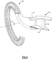
- Each circumferentially adjacent vane platform 42, 44 thermally uncouple each adjacent nozzle segments 40 ( Figure 3 ). That is, the temperature environment of the turbine section 18 and the substantial aerodynamic and thermal loads are accommodated by the plurality of circumferentially adjoining nozzle segments 40 which collectively form a full, annular ring about the centerline axis A of the engine ( Figure 4 ).
- a nozzle segment 40 for a turbine nozzle is illustrated in the disclosed embodiment, it should be understood that other nozzle sections such as compressor nozzle sections may also benefit herefrom.
- Each nozzle segment 40 may include one or more circumferentially spaced turbine vanes 50 which extend radially between the vane platforms 42, 44. That is, the full, annular nozzle ring formed by the multiple of nozzle segments 40 provide the stator portion 36 of one stage in the turbine section 18.
- the rotor portion 38 generally includes a rotor disk 60 which receives a multiple of rotor blades 62 (also illustrated in Figure 5 ).
- Each rotor blade 62 includes a blade root section 64, a blade platform section 66, and a blade airfoil section 68, the blade platform section 66 between the blade root section 64 and the blade airfoil section 68.
- the blade root section 64 is fit into a corresponding slot of the turbine rotor disk 60.
- the blade airfoil section 68 is defined by an outer airfoil surface 70 between a leading edge 72 and a trailing edge 74.
- cooling air is directed to the interiors of both the turbine vanes 50 and blade airfoil section 68 in a conventional manner.
- the cooling air provides internal and film cooling. Since the stator portion 36 is static relative to the rotor portion 38, a clearance gap 80 is necessarily provided therebetween.
- the gap 80 is arranged to be as small as possible in order to minimize the hot combustion products H which may flow through the gap 80 and negatively effect the static structure 48 and the rotor disk 60.
- the hot combustion products H flow along the turbine vanes 50 and the blade airfoil section 68 within radial inner and outer annular boundaries defined by the vane platforms 42, 44, the blade platform section 66 and an outer static structure 82 outboard of the rotor blades 62.
- the relatively cooler high pressure purge airflow P pressurizes the cavity under the inner vane platform 44 and under the blade platform section 66.
- the inner vane platform 44 and the blade platform section 66 are typically at least partially overlapped in the axial flow direction of the hot combustion products H.
- the purge airflow P exits through the gap 80 in a radially outward direction as indicated by the arrows.
- the pressure of the purge airflow P outward through the gap 80 is higher than the highest pressure of the hot combustion products H to prevent the hot combustion products H from a negative effect upon the static structure 48 and the rotor disk 60.
- the static pressure of the hot combustion products H in the core flow path conventionally varies circumferentially.
- the purge airflow P may cause inefficiencies in proportion to the non-axisymmetric pressure fields of the hot combustion products H which may have circumferentially non-uniform flow fields adjacent the gaps 80. Were the hot combustion products H flow fields to have perfectly uniform pressures in the circumferential direction, the necessity for the purge airflow P would be essentially eliminated.
- the inner vane platform 44 and the blade platform section 66 disclosed herein provide non-axisymmetric surface features to a leading portion 44L, 66L, a trailing portion 44T, 66L and various combinations thereof to counteract the non-uniform (circumferentially) static-pressure distortions engendered by hot combustion products H to reduce purge-flow requirements and also reduce aerodynamic losses.
- the trailing portion 44T is contoured in a radial direction on an undersurface 44T-L.
- the undersurface 44T-L may, in one non-limiting embodiment, be contoured to provide a non-axisymmetric surface such as a waveform surface ( Figure 6 ).
- An upper surface 44Tu of the trailing portion 44T may define a conventional axisymmetric surface.
- the undersurface 44L-L of the leading portion 44L may also be so contoured in a radial direction.
- the trailing portion 44T may also be contoured in an axial direction on a trailing edge 44TE.
- the trailing edge 44TE may, in one non-limiting embodiment, be contoured to provide a non-axisymmetric surface such as a waveform surface ( Figure 7 ).
- a leading edge 44LE may also be so contoured in an axial direction ( Figure 7 ).
- non-axisymmetric radial surface contour undersurface 44T-L of the trailing portion 44T may be combined in various manners in relation to the hot combustion products H to reduce purge-flow requirements and also reduce aerodynamic losses.
- the non-axisymmetric radial surface contour undersurface 44T-L of the trailing portion 44T may all be utilized together.
- the non-axisymmetric radial surface contour undersurface 44L-L of the leading portion 44L may all be utilized together.
- the leading portion 66L of the blade platform section 66 may be contoured in a radial direction.
- the leading edge 66LE may, alternatively or additionally, be contoured to provide an axial non-axisymmetric surface such as a waveform surface ( Figure 9 ).
- the entire platform leading edge 66LE forms the wave-like shape.
- a lower surface 66L-L and or the upper surface 66Lu of the leading portion 66L may define either a conventional axisymmetric surface or be contoured to provide a non-axisymmetric surface such as a waveform surface ( Figure 10 ).
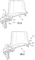
- the undersurface 66T-L of the trailing portion 66T may also be so contoured in a radial direction ( Figure 11 ).
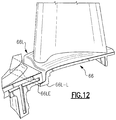
- the leading portion 66L may also be contoured in an axial direction on a leading edge 66LE.
- the leading edge 66LE may, in one non-limiting embodiment, be contoured to provide a non-axisymmetric surface such as a waveform surface.
- the trailing edge portion 66TE may be contoured in an axial direction to provide a non-axisymmetric surface such as a waveform surface.
- non-axisymmetric radial surface contour undersurface 66T-L of the trailing portion 66T may be combined in various manners in relation to the hot combustion products to reduce purge-flow requirements and also reduce aerodynamic losses.
- features of the non-axisymmetric radial and/or axial surface contour of the blade platform section 66 and features of the non-axisymmetric radial and/or axial surface contour of the inner vane platform 44 may be combined in various manners to further reduce purge-flow requirements and aerodynamic losses.
Landscapes
- Engineering & Computer Science (AREA)
- Mechanical Engineering (AREA)
- General Engineering & Computer Science (AREA)
- Physics & Mathematics (AREA)
- Fluid Mechanics (AREA)
- Turbine Rotor Nozzle Sealing (AREA)
- Structures Of Non-Positive Displacement Pumps (AREA)
Description
- The present disclosure relates to a gas turbine engine, and more particularly to a reduction in purge air.
- The core engine of a gas turbine engine typically includes a multistage axial compressor, a combustor and a high pressure turbine nozzle with one or more stages. Typical turbine nozzles, such as high pressure and low pressure turbine nozzles, define annular rings located adjacent to each turbine blade row to define axially alternate annular arrays of stator vanes and rotor blades.
- To ensure that the rotatable blades and the static vane components do not contact each other under normal operating conditions, an annular gap is provided between the stator vanes and the bladed rotor. This requires, however, that the hot gases which pass through the turbine do not leak through the annular gap. Such leakage may result in a loss in turbine efficiency.
- The conventional method to minimize hot gas leakage is the supply of high pressure purge air into the gap between the stator vanes and the bladed rotor. The purge air is directed radially outwardly over the surface of the rotatable disc and adjacent vane platform structure to exhaust through the gap into the core gas path. This minimizes hot gasses entrance into under-platform regions. These purge flows may cause some aerodynamic losses. An engine of this type is disclosed in
GB 2281356 - A rotor blade of a gas turbine engine according to claim 1.
- Various features will become apparent to those skilled in the art from the following detailed description of the disclosed non-limiting embodiment. The drawings that accompany the detailed description can be briefly described as follows:
-
Figure 1 is a general perspective view an exemplary gas turbine engine embodiment for use with the present disclosure; -
Figure 2 is an expanded sectional view of a turbine section of the gas turbine engine; -
Figure 3 is an expanded perspective view of a turbine stator vane segment; -
Figure 4 is an expanded view of a stator vane portion of one turbine stage within a turbine section of the gas turbine engine; -
Figure 5 is an expanded perspective view of a turbine rotor section; -
Figure 6 is a schematic view of an inner vane platform with a radial non-axisymmetric surface contour; -
Figure 7 is a schematic view of an inner vane platform with an axial non-axisymmetric surface contour on a platform trailing edge; -
Figure 8 is a perspective view of a turbine rotor blade; -
Figure 9 is a schematic view of a rotor blade with a radial non-axi-symmetric surface contour on a platform thereof; -
Figure 10 is a schematic view of another embodiment of a rotor blade with a radial non-axi-symmetric surface contour on a platform trailing edge; -
Figure 11 is a schematic view of a stator vane portion with an axial non-axisymmetric surface contour on a platform trailing edge; and -
Figure 12 is a schematic view of a stator vane portion with an axial non-axisymmetric surface contour on a platform leading edge. -
Figure 1 illustrates a general schematic view of agas turbine engine 10 such as a gas turbine engine for propulsion. While a particular turbofan engine is schematically illustrated in the disclosed non-limiting embodiment, it should be understood that the disclosure is applicable to other gas turbine engine configurations, including, for example, gas turbines for power generation, turbojet engines, low bypass turbofan engines, turboshaft engines, etc. - The
engine 10 includes a core engine section that houses alow spool 14 andhigh spool 24. Thelow spool 14 includes alow pressure compressor 16 and a low pressure turbine 18. The core engine section drives afan section 20 connected to thelow spool 14 either directly or through a gear train. Thehigh spool 24 includes ahigh pressure compressor 26 and high pressure turbine 28. Acombustor section 30 is arranged between thehigh pressure compressor 26 and high pressure turbine 28. The low andhigh spools - The
gas turbine engine 10 functions in the conventional manner. Air drawn through anintake 32 is accelerated by thefan section 20 and divided along a bypass flow path and a core flow path. The bypass flow path bypasses the core engine section and is exhausted to atmosphere to provide propulsive thrust. The core flow path compresses the air in thecompressor combustor section 30. The resultant hot combustion products then expand through, and thereby drive the turbines 18, 28 before being exhausted to atmosphere through anexhaust nozzle 34 to provide additional propulsive thrust. The turbines 18, 28, in response to the expansion, drive thecompressors fan section 20. - Referring to
Figure 2 , astator portion 36 and arotor portion 38 define a stage of the turbine section 18, 28. In the illustrated embodiment and for purposes of a detailed example, a single stage with thestator 36 and therotor 38 will be described herein as being disposed within a turbine section. It should be understood, however, that this application is not limited to the turbine sectional alone and may be utilized within other sections such as the fan section and compressor section as well as every stage within each section. - That
stator portion 36 includes anouter vane platform 42 and aninner vane platform 44 radially spaced apart from each other. The arcuateouter vane platform 42 may form a portion of an outercore engine structure 46 and the arcuateinner vane platform 44 may form a portion of an innercore engine structure 48 to at least partially define an annular turbine nozzle core gas flow path. - Each circumferentially
adjacent vane platform Figure 3 ). That is, the temperature environment of the turbine section 18 and the substantial aerodynamic and thermal loads are accommodated by the plurality of circumferentially adjoiningnozzle segments 40 which collectively form a full, annular ring about the centerline axis A of the engine (Figure 4 ). Although anozzle segment 40 for a turbine nozzle is illustrated in the disclosed embodiment, it should be understood that other nozzle sections such as compressor nozzle sections may also benefit herefrom. - Each
nozzle segment 40 may include one or more circumferentially spacedturbine vanes 50 which extend radially between thevane platforms nozzle segments 40 provide thestator portion 36 of one stage in the turbine section 18. - The
rotor portion 38 generally includes arotor disk 60 which receives a multiple of rotor blades 62 (also illustrated inFigure 5 ). Eachrotor blade 62 includes ablade root section 64, ablade platform section 66, and ablade airfoil section 68, theblade platform section 66 between theblade root section 64 and theblade airfoil section 68. Theblade root section 64 is fit into a corresponding slot of theturbine rotor disk 60. Theblade airfoil section 68 is defined by anouter airfoil surface 70 between a leadingedge 72 and atrailing edge 74. - Typically, cooling air is directed to the interiors of both the turbine vanes 50 and
blade airfoil section 68 in a conventional manner. The cooling air provides internal and film cooling. Since thestator portion 36 is static relative to therotor portion 38, aclearance gap 80 is necessarily provided therebetween. Thegap 80 is arranged to be as small as possible in order to minimize the hot combustion products H which may flow through thegap 80 and negatively effect thestatic structure 48 and therotor disk 60. - The hot combustion products H flow along the turbine vanes 50 and the
blade airfoil section 68 within radial inner and outer annular boundaries defined by thevane platforms blade platform section 66 and an outerstatic structure 82 outboard of therotor blades 62. The relatively cooler high pressure purge airflow P pressurizes the cavity under theinner vane platform 44 and under theblade platform section 66. Theinner vane platform 44 and theblade platform section 66 are typically at least partially overlapped in the axial flow direction of the hot combustion products H. - Although tight tolerances are maintained at the
gap 80, variation occurs axially as theengine 10 expands and contracts over typical engine operating cycles. The purge airflow P exits through thegap 80 in a radially outward direction as indicated by the arrows. The pressure of the purge airflow P outward through thegap 80 is higher than the highest pressure of the hot combustion products H to prevent the hot combustion products H from a negative effect upon thestatic structure 48 and therotor disk 60. - The static pressure of the hot combustion products H in the core flow path conventionally varies circumferentially. The purge airflow P may cause inefficiencies in proportion to the non-axisymmetric pressure fields of the hot combustion products H which may have circumferentially non-uniform flow fields adjacent the
gaps 80. Were the hot combustion products H flow fields to have perfectly uniform pressures in the circumferential direction, the necessity for the purge airflow P would be essentially eliminated. - The
inner vane platform 44 and theblade platform section 66 disclosed herein provide non-axisymmetric surface features to a leadingportion portion - Referring to
Figure 3 , the trailingportion 44T is contoured in a radial direction on anundersurface 44T-L. The undersurface 44T-L may, in one non-limiting embodiment, be contoured to provide a non-axisymmetric surface such as a waveform surface (Figure 6 ). An upper surface 44Tu of the trailingportion 44T may define a conventional axisymmetric surface. Alternatively, or in addition thereto, theundersurface 44L-L of the leadingportion 44L may also be so contoured in a radial direction. - The trailing
portion 44T may also be contoured in an axial direction on a trailing edge 44TE. The trailing edge 44TE may, in one non-limiting embodiment, be contoured to provide a non-axisymmetric surface such as a waveform surface (Figure 7 ). Alternatively, or in addition thereto, a leading edge 44LE may also be so contoured in an axial direction (Figure 7 ). - It should be understood that the non-axisymmetric radial
surface contour undersurface 44T-L of the trailingportion 44T, the non-axisymmetric radialsurface contour undersurface 44L-L of the leadingportion 44L, the non-axisymmetric axial surface contour of the trailing edge 44TE, and the non-axisymmetric axial surface contour of the leading edge 44LE may be combined in various manners in relation to the hot combustion products H to reduce purge-flow requirements and also reduce aerodynamic losses. For example, the non-axisymmetric radialsurface contour undersurface 44T-L of the trailingportion 44T, the non-axisymmetric radialsurface contour undersurface 44L-L of the leadingportion 44L, the non-axisymmetric axial surface contour of the trailing edge 44TE, and the non-axisymmetric axial surface contour of the leading edge 44LE may all be utilized together. - Referring to
Figure 8 , the leadingportion 66L of theblade platform section 66 may be contoured in a radial direction. The leading edge 66LE may, alternatively or additionally, be contoured to provide an axial non-axisymmetric surface such as a waveform surface (Figure 9 ). In this non-limiting embodiment, the entire platform leading edge 66LE forms the wave-like shape. Alower surface 66L-L and or the upper surface 66Lu of the leadingportion 66L may define either a conventional axisymmetric surface or be contoured to provide a non-axisymmetric surface such as a waveform surface (Figure 10 ). Alternatively, or in addition thereto, theundersurface 66T-L of the trailingportion 66T may also be so contoured in a radial direction (Figure 11 ). - Referring to
Figure 12 , the leadingportion 66L may also be contoured in an axial direction on a leading edge 66LE. The leading edge 66LE may, in one non-limiting embodiment, be contoured to provide a non-axisymmetric surface such as a waveform surface. Alternatively, or in addition thereto, the trailing edge portion 66TE may be contoured in an axial direction to provide a non-axisymmetric surface such as a waveform surface. - It should be understood that the non-axisymmetric radial
surface contour undersurface 66T-L of the trailingportion 66T, the non-axisymmetric radialsurface contour undersurface 66L-L of the leadingportion 66L, the non-axisymmetric axial surface contour of the trailing edge 66TE, and the non-axisymmetric axial surface contour of the leading edge 66LE may be combined in various manners in relation to the hot combustion products to reduce purge-flow requirements and also reduce aerodynamic losses. Furthermore, features of the non-axisymmetric radial and/or axial surface contour of theblade platform section 66 and features of the non-axisymmetric radial and/or axial surface contour of theinner vane platform 44 may be combined in various manners to further reduce purge-flow requirements and aerodynamic losses. - It should be understood that relative positional terms such as "forward," "aft," "upper," "lower," "above," "below," and the like are with reference to the normal operational attitude of the vehicle and should not be considered otherwise limiting.
- It should be understood that like reference numerals identify corresponding or similar elements throughout the several drawings. It should also be understood that although a particular component arrangement is disclosed in the illustrated embodiment, other arrangements will benefit herefrom.
- Although particular step sequences are shown, described, and claimed, it should be understood that steps may be performed in any order, separated or combined unless otherwise indicated and will still benefit from the present disclosure.
- The foregoing description is exemplary rather than defined by the limitations within. Various non-limiting embodiments are disclosed herein, however, one of ordinary skill in the art would recognize that various modifications and variations in light of the above teachings will fall within the scope of the appended claims. It is therefore to be understood that within the scope of the appended claims, the disclosure may be practiced other than as specifically described. For that reason the appended claims should be studied to determine true scope and content.
Claims (10)
- A rotor blade (62) of a gas turbine engine (10) comprising:a root section (64);an airfoil section (68); anda platform section (66) between said root section (64) and said airfoil section (68),and said platform section (66) is spaced from a radially inner vane platform (42, 44) to provide a clearance gap (80) defined in a radial direction between an upper surface of said radially inner vane platform (42, 44) and the platform section (66), characterized in that said platform section (66) has a non-axisymmetric surface contour defining a portion of said clearance gap (80).
- The rotor blade (62) as recited in claim 1, wherein said rotor blade (62) is a turbine blade.
- The rotor blade (62) as recited in claims 1 or 2, wherein said non-axisymmetric surface contour is located on an undersurface (66L-L, 66T-L) of said platform section (66).
- The rotor blade (62) as recited in claim 3, wherein said non-axisymmetric surface contour is located adjacent a trailing edge (66TE) of said platform section (66).
- The rotor blade (62) as recited in claim 3, wherein said non-axisymmetric surface contour is located adjacent a leading edge (66LE) of said platform section (66).
- The rotor blade (62) as recited in any preceding claim, wherein an upper surface (66Lu, 66Tu) of said platform section (66) is non-axisymmetric.
- The rotor blade (62) as recited in claims 1 or 2, wherein said non-axisymmetric surface contour is located along a trailing edge (66TE) of said platform section.
- The rotor blade (62) as recited in claims 1 or 2, wherein said non-axisymmetric surface contour is located along a leading edge (66LE) of said platform section.
- The rotor blade (62) as recited in any preceding claim, wherein said non-axisymmetric surface contour is contoured in a radial direction.
- The rotor blade (62) as recited in any preceding claim, wherein said non-axisymmetric surface contour is contoured in an axial direction.
Applications Claiming Priority (2)
| Application Number | Priority Date | Filing Date | Title |
|---|---|---|---|
| US12/730,191 US8356975B2 (en) | 2010-03-23 | 2010-03-23 | Gas turbine engine with non-axisymmetric surface contoured vane platform |
| EP11250268.7A EP2369138B1 (en) | 2010-03-23 | 2011-03-09 | Gas turbine engine with non-axisymmetric surface contoured vane platform |
Related Parent Applications (2)
| Application Number | Title | Priority Date | Filing Date |
|---|---|---|---|
| EP11250268.7A Division EP2369138B1 (en) | 2010-03-23 | 2011-03-09 | Gas turbine engine with non-axisymmetric surface contoured vane platform |
| EP11250268.7A Division-Into EP2369138B1 (en) | 2010-03-23 | 2011-03-09 | Gas turbine engine with non-axisymmetric surface contoured vane platform |
Publications (2)
| Publication Number | Publication Date |
|---|---|
| EP2937515A1 EP2937515A1 (en) | 2015-10-28 |
| EP2937515B1 true EP2937515B1 (en) | 2016-12-14 |
Family
ID=44281087
Family Applications (2)
| Application Number | Title | Priority Date | Filing Date |
|---|---|---|---|
| EP15161183.7A Active EP2937515B1 (en) | 2010-03-23 | 2011-03-09 | Gas turbine engine with non-axisymmetric surface contoured vane platform |
| EP11250268.7A Active EP2369138B1 (en) | 2010-03-23 | 2011-03-09 | Gas turbine engine with non-axisymmetric surface contoured vane platform |
Family Applications After (1)
| Application Number | Title | Priority Date | Filing Date |
|---|---|---|---|
| EP11250268.7A Active EP2369138B1 (en) | 2010-03-23 | 2011-03-09 | Gas turbine engine with non-axisymmetric surface contoured vane platform |
Country Status (2)
| Country | Link |
|---|---|
| US (1) | US8356975B2 (en) |
| EP (2) | EP2937515B1 (en) |
Families Citing this family (33)
| Publication number | Priority date | Publication date | Assignee | Title |
|---|---|---|---|---|
| US9976433B2 (en) * | 2010-04-02 | 2018-05-22 | United Technologies Corporation | Gas turbine engine with non-axisymmetric surface contoured rotor blade platform |
| US8926267B2 (en) | 2011-04-12 | 2015-01-06 | Siemens Energy, Inc. | Ambient air cooling arrangement having a pre-swirler for gas turbine engine blade cooling |
| US8967973B2 (en) * | 2011-10-26 | 2015-03-03 | General Electric Company | Turbine bucket platform shaping for gas temperature control and related method |
| US8827643B2 (en) * | 2011-10-26 | 2014-09-09 | General Electric Company | Turbine bucket platform leading edge scalloping for performance and secondary flow and related method |
| ES2894281T3 (en) * | 2011-12-20 | 2022-02-14 | Mtu Aero Engines Gmbh | Turbomachinery and turbomachinery stage |
| ES2891562T3 (en) * | 2011-12-20 | 2022-01-28 | MTU Aero Engines AG | Turbomachinery and turbomachinery stage |
| US9103213B2 (en) * | 2012-02-29 | 2015-08-11 | General Electric Company | Scalloped surface turbine stage with purge trough |
| US9382807B2 (en) * | 2012-05-08 | 2016-07-05 | United Technologies Corporation | Non-axisymmetric rim cavity features to improve sealing efficiencies |
| US9267386B2 (en) | 2012-06-29 | 2016-02-23 | United Technologies Corporation | Fairing assembly |
| JP6035946B2 (en) * | 2012-07-26 | 2016-11-30 | 株式会社Ihi | Engine duct and aircraft engine |
| US10344601B2 (en) | 2012-08-17 | 2019-07-09 | United Technologies Corporation | Contoured flowpath surface |
| US20140142889A1 (en) * | 2012-09-28 | 2014-05-22 | United Technologies Corporation | Throat Area Calculation for a Section of a Gas Turbine Engine |
| US9181816B2 (en) | 2013-01-23 | 2015-11-10 | Siemens Aktiengesellschaft | Seal assembly including grooves in an aft facing side of a platform in a gas turbine engine |
| US10047617B2 (en) | 2013-04-18 | 2018-08-14 | United Technologies Corporation | Gas turbine engine airfoil platform edge geometry |
| EP3033497B1 (en) * | 2013-08-12 | 2020-02-26 | United Technologies Corporation | Gas turbine engine and corresponding method of assembling |
| WO2015195112A1 (en) | 2014-06-18 | 2015-12-23 | Siemens Energy, Inc. | End wall configuration for gas turbine engine |
| EP3020929A1 (en) | 2014-11-17 | 2016-05-18 | United Technologies Corporation | Airfoil platform rim seal assembly |
| DE102015206384A1 (en) | 2015-04-09 | 2016-10-13 | Rolls-Royce Deutschland Ltd & Co Kg | Shroud arrangement of a row of blades of stator or rotor blades |
| US10240462B2 (en) | 2016-01-29 | 2019-03-26 | General Electric Company | End wall contour for an axial flow turbine stage |
| US10570767B2 (en) * | 2016-02-05 | 2020-02-25 | General Electric Company | Gas turbine engine with a cooling fluid path |
| US10436068B2 (en) * | 2016-02-12 | 2019-10-08 | General Electric Company | Flowpath contouring |
| CN105626157B (en) * | 2016-03-02 | 2017-03-01 | 哈尔滨工程大学 | A turbine with a multiple rim seal structure including adaptive jet holes |
| FR3052804B1 (en) * | 2016-06-16 | 2018-05-25 | Safran Aircraft Engines | VOLUNTARILY UNSUBSCRIBED WHEEL |
| CN107869362B (en) * | 2016-09-26 | 2019-09-20 | 中国航发商用航空发动机有限责任公司 | Rim sealing structure, turbine and gas turbine |
| US11111858B2 (en) * | 2017-01-27 | 2021-09-07 | General Electric Company | Cool core gas turbine engine |
| ES2750815T3 (en) | 2017-07-14 | 2020-03-27 | MTU Aero Engines AG | Profiled wing grille for turbomachines |
| US11149561B2 (en) | 2019-08-12 | 2021-10-19 | Rolls-Royce Plc | System and method for making ceramic matrix composite vane with profiled end walls |
| DE102020115106B4 (en) | 2020-06-08 | 2022-08-25 | Man Energy Solutions Se | turbine nozzle |
| US20220082023A1 (en) * | 2020-09-15 | 2022-03-17 | General Electric Company | Turbine blade with non-axisymmetric forward feature |
| US11428160B2 (en) | 2020-12-31 | 2022-08-30 | General Electric Company | Gas turbine engine with interdigitated turbine and gear assembly |
| DE102022117268A1 (en) | 2022-07-12 | 2024-01-18 | MTU Aero Engines AG | Rotor blade and rotor blade arrangement for a turbomachine |
| US11939880B1 (en) | 2022-11-03 | 2024-03-26 | General Electric Company | Airfoil assembly with flow surface |
| US12442304B1 (en) * | 2025-03-12 | 2025-10-14 | General Electric Company | Gas turbine engine with bow wave mitigation |
Family Cites Families (64)
| Publication number | Priority date | Publication date | Assignee | Title |
|---|---|---|---|---|
| US2918254A (en) | 1954-05-10 | 1959-12-22 | Hausammann Werner | Turborunner |
| US3014695A (en) * | 1960-02-03 | 1961-12-26 | Gen Electric | Turbine bucket retaining means |
| US4218178A (en) | 1978-03-31 | 1980-08-19 | General Motors Corporation | Turbine vane structure |
| JPS5669402A (en) * | 1979-11-09 | 1981-06-10 | Hitachi Ltd | Structure of blade train with shroud |
| US4271005A (en) | 1979-12-03 | 1981-06-02 | United Technologies Corporation | Workpiece support apparatus for use with cathode sputtering devices |
| US4283822A (en) * | 1979-12-26 | 1981-08-18 | General Electric Company | Method of fabricating composite nozzles for water cooled gas turbines |
| DE3023466C2 (en) | 1980-06-24 | 1982-11-25 | MTU Motoren- und Turbinen-Union München GmbH, 8000 München | Device for reducing secondary flow losses in a bladed flow channel |
| US4677828A (en) | 1983-06-16 | 1987-07-07 | United Technologies Corporation | Circumferentially area ruled duct |
| FR2643940B1 (en) | 1989-03-01 | 1991-05-17 | Snecma | MOBILE VANE OF TURBOMACHINE WITH MOMENT OF COMPENSATED FOOT |
| MC2073A1 (en) * | 1989-09-21 | 1990-10-03 | Baria Guy | BARIA SLUDGE INJECTOR |
| US5397215A (en) | 1993-06-14 | 1995-03-14 | United Technologies Corporation | Flow directing assembly for the compression section of a rotary machine |
| GB2281356B (en) | 1993-08-20 | 1997-01-29 | Rolls Royce Plc | Gas turbine engine turbine |
| GB2294732A (en) | 1994-11-05 | 1996-05-08 | Rolls Royce Plc | Integral disc seal for turbomachine |
| KR20010005910A (en) * | 1997-04-01 | 2001-01-15 | 칼 하인쯔 호르닝어 | Surface structure for the wall of a flow channel or a turbine blade |
| DE29715180U1 (en) | 1997-08-23 | 1997-10-16 | MTU Motoren- und Turbinen-Union München GmbH, 80995 München | Guide blade for a gas turbine |
| WO2000057032A1 (en) | 1999-03-24 | 2000-09-28 | Siemens Aktiengesellschaft | Guide blade and guide blade rim for a fluid-flow machine and component for delimiting a flow channel |
| US6276432B1 (en) | 1999-06-10 | 2001-08-21 | Howmet Research Corporation | Directional solidification method and apparatus |
| GB9915648D0 (en) * | 1999-07-06 | 1999-09-01 | Rolls Royce Plc | Improvement in or relating to turbine blades |
| US6511294B1 (en) | 1999-09-23 | 2003-01-28 | General Electric Company | Reduced-stress compressor blisk flowpath |
| US6343912B1 (en) | 1999-12-07 | 2002-02-05 | General Electric Company | Gas turbine or jet engine stator vane frame |
| GB0003676D0 (en) | 2000-02-17 | 2000-04-05 | Abb Alstom Power Nv | Aerofoils |
| JP2001271602A (en) | 2000-03-27 | 2001-10-05 | Honda Motor Co Ltd | Gas turbine engine |
| AR033517A1 (en) * | 2000-04-08 | 2003-12-26 | Astrazeneca Ab | PIPERIDINE DERIVATIVES, PROCESS FOR THE PREPARATION AND USE OF THESE DERIVATIVES IN THE MANUFACTURE OF MEDICINES |
| DE10051223A1 (en) | 2000-10-16 | 2002-04-25 | Alstom Switzerland Ltd | Connectable stator elements |
| US6471474B1 (en) | 2000-10-20 | 2002-10-29 | General Electric Company | Method and apparatus for reducing rotor assembly circumferential rim stress |
| DE10064265A1 (en) | 2000-12-22 | 2002-07-04 | Alstom Switzerland Ltd | Device and method for cooling a platform of a turbine blade |
| US6430917B1 (en) | 2001-02-09 | 2002-08-13 | The Regents Of The University Of California | Single rotor turbine engine |
| US6431820B1 (en) | 2001-02-28 | 2002-08-13 | General Electric Company | Methods and apparatus for cooling gas turbine engine blade tips |
| US6514041B1 (en) | 2001-09-12 | 2003-02-04 | Alstom (Switzerland) Ltd | Carrier for guide vane and heat shield segment |
| EP1329593B1 (en) | 2002-01-17 | 2005-03-23 | Siemens Aktiengesellschaft | Turbine blade with a hot gas suporting platform and a mechanical load suporting platform |
| US6609880B2 (en) * | 2001-11-15 | 2003-08-26 | General Electric Company | Methods and apparatus for cooling gas turbine nozzles |
| US6672832B2 (en) | 2002-01-07 | 2004-01-06 | General Electric Company | Step-down turbine platform |
| ATE467749T1 (en) | 2002-01-17 | 2010-05-15 | Siemens Ag | CAST TURBINE GUIDE BLADE WITH HOOK BASE |
| US6821087B2 (en) * | 2002-01-21 | 2004-11-23 | Honda Giken Kogyo Kabushiki Kaisha | Flow-rectifying member and its unit and method for producing flow-rectifying member |
| US6669445B2 (en) | 2002-03-07 | 2003-12-30 | United Technologies Corporation | Endwall shape for use in turbomachinery |
| EP1413715A1 (en) | 2002-10-21 | 2004-04-28 | Siemens Aktiengesellschaft | Impingement cooling of a gas turbine rotor blade platform |
| US6761536B1 (en) | 2003-01-31 | 2004-07-13 | Power Systems Mfg, Llc | Turbine blade platform trailing edge undercut |
| US6991428B2 (en) | 2003-06-12 | 2006-01-31 | Pratt & Whitney Canada Corp. | Fan blade platform feature for improved blade-off performance |
| US7044718B1 (en) | 2003-07-08 | 2006-05-16 | The Regents Of The University Of California | Radial-radial single rotor turbine |
| EP1515000B1 (en) * | 2003-09-09 | 2016-03-09 | Alstom Technology Ltd | Blading of a turbomachine with contoured shrouds |
| US7600972B2 (en) | 2003-10-31 | 2009-10-13 | General Electric Company | Methods and apparatus for cooling gas turbine engine rotor assemblies |
| EP1557534A1 (en) | 2004-01-20 | 2005-07-27 | Siemens Aktiengesellschaft | Turbine blade and gas turbine with such a turbine blade |
| JP2005233141A (en) | 2004-02-23 | 2005-09-02 | Mitsubishi Heavy Ind Ltd | Moving blade and gas turbine using same |
| US7452184B2 (en) | 2004-12-13 | 2008-11-18 | Pratt & Whitney Canada Corp. | Airfoil platform impingement cooling |
| US7134842B2 (en) | 2004-12-24 | 2006-11-14 | General Electric Company | Scalloped surface turbine stage |
| JP4860941B2 (en) * | 2005-04-27 | 2012-01-25 | 本田技研工業株式会社 | Rectifying member unit and manufacturing method thereof |
| US7717046B2 (en) * | 2005-04-29 | 2010-05-18 | Pratt & Whitney Rocketdyne, Inc. | High pressure dry coal slurry extrusion pump |
| EP1731711A1 (en) * | 2005-06-10 | 2006-12-13 | Siemens Aktiengesellschaft | Transition from combustion chamber to turbine, heat shield, and turbine vane in a gas turbine |
| US7467922B2 (en) | 2005-07-25 | 2008-12-23 | Siemens Aktiengesellschaft | Cooled turbine blade or vane for a gas turbine, and use of a turbine blade or vane of this type |
| US7300253B2 (en) | 2005-07-25 | 2007-11-27 | Siemens Aktiengesellschaft | Gas turbine blade or vane and platform element for a gas turbine blade or vane ring of a gas turbine, supporting structure for securing gas turbine blades or vanes arranged in a ring, gas turbine blade or vane ring and the use of a gas turbine blade or vane ring |
| US7467924B2 (en) | 2005-08-16 | 2008-12-23 | United Technologies Corporation | Turbine blade including revised platform |
| US7384243B2 (en) | 2005-08-30 | 2008-06-10 | General Electric Company | Stator vane profile optimization |
| US7628578B2 (en) | 2005-09-12 | 2009-12-08 | Pratt & Whitney Canada Corp. | Vane assembly with improved vane roots |
| US7484936B2 (en) | 2005-09-26 | 2009-02-03 | Pratt & Whitney Canada Corp. | Blades for a gas turbine engine with integrated sealing plate and method |
| US7540709B1 (en) | 2005-10-20 | 2009-06-02 | Florida Turbine Technologies, Inc. | Box rim cavity for a gas turbine engine |
| US7465155B2 (en) | 2006-02-27 | 2008-12-16 | Honeywell International Inc. | Non-axisymmetric end wall contouring for a turbomachine blade row |
| GB2436597A (en) | 2006-03-27 | 2007-10-03 | Alstom Technology Ltd | Turbine blade and diaphragm |
| US7625172B2 (en) | 2006-04-26 | 2009-12-01 | United Technologies Corporation | Vane platform cooling |
| US7597536B1 (en) | 2006-06-14 | 2009-10-06 | Florida Turbine Technologies, Inc. | Turbine airfoil with de-coupled platform |
| US7581930B2 (en) | 2006-08-16 | 2009-09-01 | United Technologies Corporation | High lift transonic turbine blade |
| US7497663B2 (en) | 2006-10-26 | 2009-03-03 | General Electric Company | Rotor blade profile optimization |
| ATE447662T1 (en) * | 2007-01-18 | 2009-11-15 | Siemens Ag | GUIDE VANE FOR A GAS TURBINE |
| US8206115B2 (en) | 2008-09-26 | 2012-06-26 | General Electric Company | Scalloped surface turbine stage with trailing edge ridges |
| US8133015B2 (en) | 2008-09-30 | 2012-03-13 | General Electric Company | Turbine nozzle for a gas turbine engine |
-
2010
- 2010-03-23 US US12/730,191 patent/US8356975B2/en active Active
-
2011
- 2011-03-09 EP EP15161183.7A patent/EP2937515B1/en active Active
- 2011-03-09 EP EP11250268.7A patent/EP2369138B1/en active Active
Also Published As
| Publication number | Publication date |
|---|---|
| US8356975B2 (en) | 2013-01-22 |
| EP2937515A1 (en) | 2015-10-28 |
| EP2369138B1 (en) | 2018-01-03 |
| EP2369138A1 (en) | 2011-09-28 |
| US20110236200A1 (en) | 2011-09-29 |
Similar Documents
| Publication | Publication Date | Title |
|---|---|---|
| EP2937515B1 (en) | Gas turbine engine with non-axisymmetric surface contoured vane platform | |
| US9976433B2 (en) | Gas turbine engine with non-axisymmetric surface contoured rotor blade platform | |
| US11021990B2 (en) | Shroud sealing for a gas turbine engine | |
| EP2961943B1 (en) | Method and apparatus for handling pre-diffuser flow to a bearing compartment | |
| EP3594452B1 (en) | Seal segment for a gas turbine engine | |
| EP2998520B1 (en) | Inter stage seal for gas turbine engine | |
| US10247028B2 (en) | Gas turbine engine blade outer air seal thermal control system | |
| US20180010473A1 (en) | Attachment Faces for Clamped Turbine Stator of a Gas Turbine Engine | |
| US8985942B2 (en) | Turbine exhaust case duct | |
| US20090067978A1 (en) | Variable area turbine vane arrangement | |
| US20150030443A1 (en) | Split damped outer shroud for gas turbine engine stator arrays | |
| US20220213802A1 (en) | System for controlling blade clearances within a gas turbine engine | |
| EP3617458B1 (en) | Annular seal for a gas turbine engine | |
| EP3023594B1 (en) | Stator assembly with pad interface for a gas turbine engine | |
| US20240052758A1 (en) | Gas turbine engine exhaust case with blade shroud and stiffeners | |
| EP2957721B1 (en) | Turbine section of a gas turbine engine, with disk cooling and an interstage seal having a particular geometry | |
| CA2955385A1 (en) | Spline seal for a gas turbine engine | |
| EP3000966B1 (en) | Method and assembly for reducing secondary heat in a gas turbine engine | |
| EP2995778B1 (en) | Method and assembly for reducing secondary heat in a gas turbine engine | |
| US12049904B2 (en) | Tandem blade rotor disk | |
| EP3495623B1 (en) | Vane, corresponding gas turbine engine and turbine |
Legal Events
| Date | Code | Title | Description |
|---|---|---|---|
| PUAI | Public reference made under article 153(3) epc to a published international application that has entered the european phase |
Free format text: ORIGINAL CODE: 0009012 |
|
| AC | Divisional application: reference to earlier application |
Ref document number: 2369138 Country of ref document: EP Kind code of ref document: P |
|
| AK | Designated contracting states |
Kind code of ref document: A1 Designated state(s): AL AT BE BG CH CY CZ DE DK EE ES FI FR GB GR HR HU IE IS IT LI LT LU LV MC MK MT NL NO PL PT RO RS SE SI SK SM TR |
|
| 17P | Request for examination filed |
Effective date: 20160427 |
|
| RBV | Designated contracting states (corrected) |
Designated state(s): AL AT BE BG CH CY CZ DE DK EE ES FI FR GB GR HR HU IE IS IT LI LT LU LV MC MK MT NL NO PL PT RO RS SE SI SK SM TR |
|
| GRAP | Despatch of communication of intention to grant a patent |
Free format text: ORIGINAL CODE: EPIDOSNIGR1 |
|
| INTG | Intention to grant announced |
Effective date: 20160621 |
|
| RAP1 | Party data changed (applicant data changed or rights of an application transferred) |
Owner name: UNITED TECHNOLOGIES CORPORATION |
|
| GRAS | Grant fee paid |
Free format text: ORIGINAL CODE: EPIDOSNIGR3 |
|
| GRAA | (expected) grant |
Free format text: ORIGINAL CODE: 0009210 |
|
| AC | Divisional application: reference to earlier application |
Ref document number: 2369138 Country of ref document: EP Kind code of ref document: P |
|
| AK | Designated contracting states |
Kind code of ref document: B1 Designated state(s): AL AT BE BG CH CY CZ DE DK EE ES FI FR GB GR HR HU IE IS IT LI LT LU LV MC MK MT NL NO PL PT RO RS SE SI SK SM TR |
|
| REG | Reference to a national code |
Ref country code: GB Ref legal event code: FG4D |
|
| REG | Reference to a national code |
Ref country code: CH Ref legal event code: EP |
|
| REG | Reference to a national code |
Ref country code: IE Ref legal event code: FG4D |
|
| REG | Reference to a national code |
Ref country code: AT Ref legal event code: REF Ref document number: 853782 Country of ref document: AT Kind code of ref document: T Effective date: 20170115 |
|
| REG | Reference to a national code |
Ref country code: DE Ref legal event code: R096 Ref document number: 602011033519 Country of ref document: DE |
|
| PG25 | Lapsed in a contracting state [announced via postgrant information from national office to epo] |
Ref country code: LV Free format text: LAPSE BECAUSE OF FAILURE TO SUBMIT A TRANSLATION OF THE DESCRIPTION OR TO PAY THE FEE WITHIN THE PRESCRIBED TIME-LIMIT Effective date: 20161214 |
|
| REG | Reference to a national code |
Ref country code: LT Ref legal event code: MG4D |
|
| REG | Reference to a national code |
Ref country code: NL Ref legal event code: MP Effective date: 20161214 |
|
| PG25 | Lapsed in a contracting state [announced via postgrant information from national office to epo] |
Ref country code: GR Free format text: LAPSE BECAUSE OF FAILURE TO SUBMIT A TRANSLATION OF THE DESCRIPTION OR TO PAY THE FEE WITHIN THE PRESCRIBED TIME-LIMIT Effective date: 20170315 Ref country code: NO Free format text: LAPSE BECAUSE OF FAILURE TO SUBMIT A TRANSLATION OF THE DESCRIPTION OR TO PAY THE FEE WITHIN THE PRESCRIBED TIME-LIMIT Effective date: 20170314 Ref country code: LT Free format text: LAPSE BECAUSE OF FAILURE TO SUBMIT A TRANSLATION OF THE DESCRIPTION OR TO PAY THE FEE WITHIN THE PRESCRIBED TIME-LIMIT Effective date: 20161214 Ref country code: SE Free format text: LAPSE BECAUSE OF FAILURE TO SUBMIT A TRANSLATION OF THE DESCRIPTION OR TO PAY THE FEE WITHIN THE PRESCRIBED TIME-LIMIT Effective date: 20161214 |
|
| REG | Reference to a national code |
Ref country code: AT Ref legal event code: MK05 Ref document number: 853782 Country of ref document: AT Kind code of ref document: T Effective date: 20161214 |
|
| PG25 | Lapsed in a contracting state [announced via postgrant information from national office to epo] |
Ref country code: FI Free format text: LAPSE BECAUSE OF FAILURE TO SUBMIT A TRANSLATION OF THE DESCRIPTION OR TO PAY THE FEE WITHIN THE PRESCRIBED TIME-LIMIT Effective date: 20161214 Ref country code: HR Free format text: LAPSE BECAUSE OF FAILURE TO SUBMIT A TRANSLATION OF THE DESCRIPTION OR TO PAY THE FEE WITHIN THE PRESCRIBED TIME-LIMIT Effective date: 20161214 Ref country code: RS Free format text: LAPSE BECAUSE OF FAILURE TO SUBMIT A TRANSLATION OF THE DESCRIPTION OR TO PAY THE FEE WITHIN THE PRESCRIBED TIME-LIMIT Effective date: 20161214 |
|
| PG25 | Lapsed in a contracting state [announced via postgrant information from national office to epo] |
Ref country code: NL Free format text: LAPSE BECAUSE OF FAILURE TO SUBMIT A TRANSLATION OF THE DESCRIPTION OR TO PAY THE FEE WITHIN THE PRESCRIBED TIME-LIMIT Effective date: 20161214 |
|
| REG | Reference to a national code |
Ref country code: DE Ref legal event code: R082 Ref document number: 602011033519 Country of ref document: DE Representative=s name: SCHMITT-NILSON SCHRAUD WAIBEL WOHLFROM PATENTA, DE |
|
| PG25 | Lapsed in a contracting state [announced via postgrant information from national office to epo] |
Ref country code: RO Free format text: LAPSE BECAUSE OF FAILURE TO SUBMIT A TRANSLATION OF THE DESCRIPTION OR TO PAY THE FEE WITHIN THE PRESCRIBED TIME-LIMIT Effective date: 20161214 Ref country code: EE Free format text: LAPSE BECAUSE OF FAILURE TO SUBMIT A TRANSLATION OF THE DESCRIPTION OR TO PAY THE FEE WITHIN THE PRESCRIBED TIME-LIMIT Effective date: 20161214 Ref country code: IS Free format text: LAPSE BECAUSE OF FAILURE TO SUBMIT A TRANSLATION OF THE DESCRIPTION OR TO PAY THE FEE WITHIN THE PRESCRIBED TIME-LIMIT Effective date: 20170414 Ref country code: SK Free format text: LAPSE BECAUSE OF FAILURE TO SUBMIT A TRANSLATION OF THE DESCRIPTION OR TO PAY THE FEE WITHIN THE PRESCRIBED TIME-LIMIT Effective date: 20161214 Ref country code: CZ Free format text: LAPSE BECAUSE OF FAILURE TO SUBMIT A TRANSLATION OF THE DESCRIPTION OR TO PAY THE FEE WITHIN THE PRESCRIBED TIME-LIMIT Effective date: 20161214 |
|
| PG25 | Lapsed in a contracting state [announced via postgrant information from national office to epo] |
Ref country code: PT Free format text: LAPSE BECAUSE OF FAILURE TO SUBMIT A TRANSLATION OF THE DESCRIPTION OR TO PAY THE FEE WITHIN THE PRESCRIBED TIME-LIMIT Effective date: 20170414 Ref country code: ES Free format text: LAPSE BECAUSE OF FAILURE TO SUBMIT A TRANSLATION OF THE DESCRIPTION OR TO PAY THE FEE WITHIN THE PRESCRIBED TIME-LIMIT Effective date: 20161214 Ref country code: BG Free format text: LAPSE BECAUSE OF FAILURE TO SUBMIT A TRANSLATION OF THE DESCRIPTION OR TO PAY THE FEE WITHIN THE PRESCRIBED TIME-LIMIT Effective date: 20170314 Ref country code: PL Free format text: LAPSE BECAUSE OF FAILURE TO SUBMIT A TRANSLATION OF THE DESCRIPTION OR TO PAY THE FEE WITHIN THE PRESCRIBED TIME-LIMIT Effective date: 20161214 Ref country code: AT Free format text: LAPSE BECAUSE OF FAILURE TO SUBMIT A TRANSLATION OF THE DESCRIPTION OR TO PAY THE FEE WITHIN THE PRESCRIBED TIME-LIMIT Effective date: 20161214 Ref country code: BE Free format text: LAPSE BECAUSE OF FAILURE TO SUBMIT A TRANSLATION OF THE DESCRIPTION OR TO PAY THE FEE WITHIN THE PRESCRIBED TIME-LIMIT Effective date: 20161214 Ref country code: SM Free format text: LAPSE BECAUSE OF FAILURE TO SUBMIT A TRANSLATION OF THE DESCRIPTION OR TO PAY THE FEE WITHIN THE PRESCRIBED TIME-LIMIT Effective date: 20161214 Ref country code: IT Free format text: LAPSE BECAUSE OF FAILURE TO SUBMIT A TRANSLATION OF THE DESCRIPTION OR TO PAY THE FEE WITHIN THE PRESCRIBED TIME-LIMIT Effective date: 20161214 |
|
| REG | Reference to a national code |
Ref country code: DE Ref legal event code: R097 Ref document number: 602011033519 Country of ref document: DE |
|
| PLBE | No opposition filed within time limit |
Free format text: ORIGINAL CODE: 0009261 |
|
| STAA | Information on the status of an ep patent application or granted ep patent |
Free format text: STATUS: NO OPPOSITION FILED WITHIN TIME LIMIT |
|
| REG | Reference to a national code |
Ref country code: CH Ref legal event code: PL |
|
| 26N | No opposition filed |
Effective date: 20170915 |
|
| PG25 | Lapsed in a contracting state [announced via postgrant information from national office to epo] |
Ref country code: DK Free format text: LAPSE BECAUSE OF FAILURE TO SUBMIT A TRANSLATION OF THE DESCRIPTION OR TO PAY THE FEE WITHIN THE PRESCRIBED TIME-LIMIT Effective date: 20161214 Ref country code: MC Free format text: LAPSE BECAUSE OF FAILURE TO SUBMIT A TRANSLATION OF THE DESCRIPTION OR TO PAY THE FEE WITHIN THE PRESCRIBED TIME-LIMIT Effective date: 20161214 |
|
| REG | Reference to a national code |
Ref country code: IE Ref legal event code: MM4A |
|
| REG | Reference to a national code |
Ref country code: FR Ref legal event code: ST Effective date: 20171130 |
|
| PG25 | Lapsed in a contracting state [announced via postgrant information from national office to epo] |
Ref country code: LU Free format text: LAPSE BECAUSE OF NON-PAYMENT OF DUE FEES Effective date: 20170309 Ref country code: FR Free format text: LAPSE BECAUSE OF NON-PAYMENT OF DUE FEES Effective date: 20170331 |
|
| PG25 | Lapsed in a contracting state [announced via postgrant information from national office to epo] |
Ref country code: CH Free format text: LAPSE BECAUSE OF NON-PAYMENT OF DUE FEES Effective date: 20170331 Ref country code: LI Free format text: LAPSE BECAUSE OF NON-PAYMENT OF DUE FEES Effective date: 20170331 Ref country code: SI Free format text: LAPSE BECAUSE OF FAILURE TO SUBMIT A TRANSLATION OF THE DESCRIPTION OR TO PAY THE FEE WITHIN THE PRESCRIBED TIME-LIMIT Effective date: 20161214 Ref country code: IE Free format text: LAPSE BECAUSE OF NON-PAYMENT OF DUE FEES Effective date: 20170309 |
|
| PG25 | Lapsed in a contracting state [announced via postgrant information from national office to epo] |
Ref country code: MT Free format text: LAPSE BECAUSE OF NON-PAYMENT OF DUE FEES Effective date: 20170309 |
|
| PG25 | Lapsed in a contracting state [announced via postgrant information from national office to epo] |
Ref country code: HU Free format text: LAPSE BECAUSE OF FAILURE TO SUBMIT A TRANSLATION OF THE DESCRIPTION OR TO PAY THE FEE WITHIN THE PRESCRIBED TIME-LIMIT; INVALID AB INITIO Effective date: 20110309 |
|
| PG25 | Lapsed in a contracting state [announced via postgrant information from national office to epo] |
Ref country code: CY Free format text: LAPSE BECAUSE OF FAILURE TO SUBMIT A TRANSLATION OF THE DESCRIPTION OR TO PAY THE FEE WITHIN THE PRESCRIBED TIME-LIMIT Effective date: 20161214 |
|
| PG25 | Lapsed in a contracting state [announced via postgrant information from national office to epo] |
Ref country code: MK Free format text: LAPSE BECAUSE OF FAILURE TO SUBMIT A TRANSLATION OF THE DESCRIPTION OR TO PAY THE FEE WITHIN THE PRESCRIBED TIME-LIMIT Effective date: 20161214 |
|
| PG25 | Lapsed in a contracting state [announced via postgrant information from national office to epo] |
Ref country code: TR Free format text: LAPSE BECAUSE OF FAILURE TO SUBMIT A TRANSLATION OF THE DESCRIPTION OR TO PAY THE FEE WITHIN THE PRESCRIBED TIME-LIMIT Effective date: 20161214 |
|
| PG25 | Lapsed in a contracting state [announced via postgrant information from national office to epo] |
Ref country code: AL Free format text: LAPSE BECAUSE OF FAILURE TO SUBMIT A TRANSLATION OF THE DESCRIPTION OR TO PAY THE FEE WITHIN THE PRESCRIBED TIME-LIMIT Effective date: 20161214 |
|
| REG | Reference to a national code |
Ref country code: DE Ref legal event code: R081 Ref document number: 602011033519 Country of ref document: DE Owner name: RAYTHEON TECHNOLOGIES CORPORATION (N.D.GES.D.S, US Free format text: FORMER OWNER: UNITED TECHNOLOGIES CORPORATION, FARMINGTON, CONN., US Ref country code: DE Ref legal event code: R081 Ref document number: 602011033519 Country of ref document: DE Owner name: RTX CORPORATION (N.D.GES.D. STAATES DELAWARE),, US Free format text: FORMER OWNER: UNITED TECHNOLOGIES CORPORATION, FARMINGTON, CONN., US |
|
| P01 | Opt-out of the competence of the unified patent court (upc) registered |
Effective date: 20230520 |
|
| PGFP | Annual fee paid to national office [announced via postgrant information from national office to epo] |
Ref country code: DE Payment date: 20250218 Year of fee payment: 15 |
|
| PGFP | Annual fee paid to national office [announced via postgrant information from national office to epo] |
Ref country code: GB Payment date: 20250221 Year of fee payment: 15 |
|
| REG | Reference to a national code |
Ref country code: DE Ref legal event code: R081 Ref document number: 602011033519 Country of ref document: DE Owner name: RTX CORPORATION (N.D.GES.D. STAATES DELAWARE),, US Free format text: FORMER OWNER: RAYTHEON TECHNOLOGIES CORPORATION (N.D.GES.D.STAATES DELAWARE), ARLINGTON, VA, US |