EP1199268B1 - Automatic sheet feeding mechanism - Google Patents
Automatic sheet feeding mechanism Download PDFInfo
- Publication number
- EP1199268B1 EP1199268B1 EP02075141A EP02075141A EP1199268B1 EP 1199268 B1 EP1199268 B1 EP 1199268B1 EP 02075141 A EP02075141 A EP 02075141A EP 02075141 A EP02075141 A EP 02075141A EP 1199268 B1 EP1199268 B1 EP 1199268B1
- Authority
- EP
- European Patent Office
- Prior art keywords
- kicker
- stack
- sheet
- media
- paper
- Prior art date
- Legal status (The legal status is an assumption and is not a legal conclusion. Google has not performed a legal analysis and makes no representation as to the accuracy of the status listed.)
- Expired - Lifetime
Links
- 230000007246 mechanism Effects 0.000 title claims description 79
- 238000000926 separation method Methods 0.000 claims description 26
- 238000000034 method Methods 0.000 claims description 10
- 229920002799 BoPET Polymers 0.000 claims description 2
- 239000005041 Mylar™ Substances 0.000 claims description 2
- 239000004033 plastic Substances 0.000 description 6
- 230000005484 gravity Effects 0.000 description 3
- 239000000463 material Substances 0.000 description 3
- 230000000977 initiatory effect Effects 0.000 description 2
- 238000010276 construction Methods 0.000 description 1
- 230000000694 effects Effects 0.000 description 1
- 230000008030 elimination Effects 0.000 description 1
- 238000003379 elimination reaction Methods 0.000 description 1
- 238000000605 extraction Methods 0.000 description 1
- 239000002184 metal Substances 0.000 description 1
Images


Classifications
-
- B—PERFORMING OPERATIONS; TRANSPORTING
- B65—CONVEYING; PACKING; STORING; HANDLING THIN OR FILAMENTARY MATERIAL
- B65H—HANDLING THIN OR FILAMENTARY MATERIAL, e.g. SHEETS, WEBS, CABLES
- B65H3/00—Separating articles from piles
- B65H3/02—Separating articles from piles using friction forces between articles and separator
- B65H3/06—Rollers or like rotary separators
- B65H3/0607—Rollers or like rotary separators cooperating with means for automatically separating the pile from roller or rotary separator after a separation step
-
- B—PERFORMING OPERATIONS; TRANSPORTING
- B65—CONVEYING; PACKING; STORING; HANDLING THIN OR FILAMENTARY MATERIAL
- B65H—HANDLING THIN OR FILAMENTARY MATERIAL, e.g. SHEETS, WEBS, CABLES
- B65H3/00—Separating articles from piles
- B65H3/02—Separating articles from piles using friction forces between articles and separator
- B65H3/06—Rollers or like rotary separators
- B65H3/0638—Construction of the rollers or like rotary separators
-
- B—PERFORMING OPERATIONS; TRANSPORTING
- B65—CONVEYING; PACKING; STORING; HANDLING THIN OR FILAMENTARY MATERIAL
- B65H—HANDLING THIN OR FILAMENTARY MATERIAL, e.g. SHEETS, WEBS, CABLES
- B65H3/00—Separating articles from piles
- B65H3/34—Article-retaining devices controlling the release of the articles to the separators
-
- B—PERFORMING OPERATIONS; TRANSPORTING
- B65—CONVEYING; PACKING; STORING; HANDLING THIN OR FILAMENTARY MATERIAL
- B65H—HANDLING THIN OR FILAMENTARY MATERIAL, e.g. SHEETS, WEBS, CABLES
- B65H3/00—Separating articles from piles
- B65H3/46—Supplementary devices or measures to assist separation or prevent double feed
- B65H3/52—Friction retainers acting on under or rear side of article being separated
- B65H3/5207—Non-driven retainers, e.g. movable retainers being moved by the motion of the article
- B65H3/5215—Non-driven retainers, e.g. movable retainers being moved by the motion of the article the retainers positioned under articles separated from the top of the pile
- B65H3/5223—Retainers of the pad-type, e.g. friction pads
-
- B—PERFORMING OPERATIONS; TRANSPORTING
- B65—CONVEYING; PACKING; STORING; HANDLING THIN OR FILAMENTARY MATERIAL
- B65H—HANDLING THIN OR FILAMENTARY MATERIAL, e.g. SHEETS, WEBS, CABLES
- B65H3/00—Separating articles from piles
- B65H3/46—Supplementary devices or measures to assist separation or prevent double feed
- B65H3/56—Elements, e.g. scrapers, fingers, needles, brushes, acting on separated article or on edge of the pile
- B65H3/565—Elements, e.g. scrapers, fingers, needles, brushes, acting on separated article or on edge of the pile for reintroducing partially separated articles in the stack
-
- B—PERFORMING OPERATIONS; TRANSPORTING
- B65—CONVEYING; PACKING; STORING; HANDLING THIN OR FILAMENTARY MATERIAL
- B65H—HANDLING THIN OR FILAMENTARY MATERIAL, e.g. SHEETS, WEBS, CABLES
- B65H9/00—Registering, e.g. orientating, articles; Devices therefor
- B65H9/10—Pusher and like movable registers; Pusher or gripper devices which move articles into registered position
-
- B—PERFORMING OPERATIONS; TRANSPORTING
- B65—CONVEYING; PACKING; STORING; HANDLING THIN OR FILAMENTARY MATERIAL
- B65H—HANDLING THIN OR FILAMENTARY MATERIAL, e.g. SHEETS, WEBS, CABLES
- B65H2301/00—Handling processes for sheets or webs
- B65H2301/40—Type of handling process
- B65H2301/42—Piling, depiling, handling piles
- B65H2301/422—Handling piles, sets or stacks of articles
- B65H2301/4222—Squaring-up piles
-
- B—PERFORMING OPERATIONS; TRANSPORTING
- B65—CONVEYING; PACKING; STORING; HANDLING THIN OR FILAMENTARY MATERIAL
- B65H—HANDLING THIN OR FILAMENTARY MATERIAL, e.g. SHEETS, WEBS, CABLES
- B65H2404/00—Parts for transporting or guiding the handled material
- B65H2404/10—Rollers
- B65H2404/12—Rollers with at least an active member on periphery
- B65H2404/121—Rollers with at least an active member on periphery articulated around axis parallel to roller axis
-
- B—PERFORMING OPERATIONS; TRANSPORTING
- B65—CONVEYING; PACKING; STORING; HANDLING THIN OR FILAMENTARY MATERIAL
- B65H—HANDLING THIN OR FILAMENTARY MATERIAL, e.g. SHEETS, WEBS, CABLES
- B65H2404/00—Parts for transporting or guiding the handled material
- B65H2404/10—Rollers
- B65H2404/12—Rollers with at least an active member on periphery
- B65H2404/122—Rollers with at least an active member on periphery rotated around an axis parallel to the roller axis
-
- B—PERFORMING OPERATIONS; TRANSPORTING
- B65—CONVEYING; PACKING; STORING; HANDLING THIN OR FILAMENTARY MATERIAL
- B65H—HANDLING THIN OR FILAMENTARY MATERIAL, e.g. SHEETS, WEBS, CABLES
- B65H2601/00—Problem to be solved or advantage achieved
- B65H2601/20—Avoiding or preventing undesirable effects
- B65H2601/25—Damages to handled material
- B65H2601/253—Damages to handled material to particular parts of material
- B65H2601/2531—Edges
-
- Y—GENERAL TAGGING OF NEW TECHNOLOGICAL DEVELOPMENTS; GENERAL TAGGING OF CROSS-SECTIONAL TECHNOLOGIES SPANNING OVER SEVERAL SECTIONS OF THE IPC; TECHNICAL SUBJECTS COVERED BY FORMER USPC CROSS-REFERENCE ART COLLECTIONS [XRACs] AND DIGESTS
- Y10—TECHNICAL SUBJECTS COVERED BY FORMER USPC
- Y10S—TECHNICAL SUBJECTS COVERED BY FORMER USPC CROSS-REFERENCE ART COLLECTIONS [XRACs] AND DIGESTS
- Y10S271/00—Sheet feeding or delivering
- Y10S271/902—Reverse direction of sheet movement
Definitions
- the present invention relates to hard copy media control apparatus. More specifically, the present invention relates to an automatic sheet feeding mechanism for control of paper in a cut-sheet paper feeding mechanisms for use with printers, plotters, copiers, facsimile machines and the like. The present invention also relates to a method for sheet feeding.
- Paper feed mechanisms for hard copy control apparatus are well known in the art.
- automatic cut sheet printers a stack of paper is automatically fed to a printer, plotter, copier, facsimile machine, or other apparatus typically using a roller assembly or other mechanism.
- An important function of the feed mechanism is to control the parallelism between the top edge of the sheet of paper and the first line of print contained thereon, i.e., the amount of skew between the paper and the print. Even a small amount of skew between the paper and print will cause the printing to appear crooked. Larger amounts of skew may cause buckling of the paper, resulting in uneven print quality or jamming of the paper within the printer.
- the skew is generally induced when the paper is loaded into and/or picked from a stack of paper in a supply tray. Accordingly, it is desirable to minimize the amount of skew between the paper and the printing assembly once the paper has been picked and before it is printed on.
- Prior art printing devices use a variety of techniques and apparatus to minimize skew. Some minimize skew by forcing a sheet of paper into a pair of stalled rollers, creating a buckle in the paper and forcing the leading edge of the paper to be parallel with the roller pair. The rollers are then activated to advance the paper into the print zone. Such a technique requires some type of clutching mechanism to stall the rollers long enough to allow the paper to be fed into the nip between the rollers. Further, this technique requires accurate control of the paper while it is buckling, as the buckle must be large enough to correct the skew, yet small enough that the paper does not flip out of the nip between the stalled rollers.
- the feed mechanism In addition to minimizing skew, the feed mechanism must maintain accurate control of each sheet, from the time it is picked from the stack until it is ejected from the apparatus.
- the paper feed mechanisms of typical prior art printers, plotters, copiers, facsimile machines and the like use separate motors and gear arrangements to pick the paper from a stack, deliver the paper to a printing assembly, line feed the paper and eject the paper once printed.
- Such feed mechanisms often encumber the carriage drive motor and have complex timing schemes requiring triggering devices, such as solenoids.
- the large number of motors and other electrical components increases the cost of the apparatus.
- complex feed mechanisms increase the amount of time necessary to pass a page through the apparatus, as well as the chances of paper jams and skew errors.
- Kickers are used to assist in the movement of paper in sheet feeding mechanisms.
- a kicker may be used to assist in the movement of a printed page into a receiving tray as disclosed in the above-identified Jackson patent.
- kickers may be used to reset stacks of paper in a sheet feeder during a printing operation so that the printing of each sheet starts from a known initial state.
- sheet feeding mechanisms are known in the art. Typically, sheet feeding is accomplished using a roller on top of the paper and a friction pad on the bottom. In this application, the kicker assists in the movement of paper out of the nip area between the roller and the pad to prevent multi-feeds.
- EP 0 379 661 discloses an overlapped-transfer preventing paper supply device in an image-forming apparatus.
- the overlapped-transfer preventing device comprises two staggered and nested rollers.
- the bottom roller further comprises a sheet returning member, which may be formed of thin elastically deformable materials.
- the kicker is mounted on a shaft along with a separation roll.
- the kicker is a flexible strip of plastic that flexes as it engages the stack when the shaft is rotated. After the kicker has rotated around the shaft, it pushes media remaining on the separation roll back onto the stack.
- a particular aspect of this implementation is the use of the media as a separation spring between pick tires mounted on a first shaft and the separation roll mounted on a second shaft. The separation spring effect facilitates the separation of individual sheets of media from others in the stack.
- a sheet feeding mechanism having a kicker which serves to retain media on the stack.
- a cam is coupled to the pick apparatus for deflecting the kicker from the first position at which it retains media on the stack to a second position at which paper is allowed to move through the mechanism.
- the mechanism includes a frame and a shaft mounted on the frame for rotational movement relative thereto.
- the pick apparatus includes a pick tire mounted on the shaft and adapted to rotate therewith.
- the kicker is mounted on the frame for retaining media on the stack in a first position.
- the cam is adapted to deflect the kicker during a first portion of a rotational cycle and to release the kicker when the cam is in a second rotational position.
- a sheet feeding mechanism in which, the cam is contoured to provide a protruded edge which engages the kicker when the cam is counter-rotated. This forces the kicker to push media remaining on a separation roll back onto the stack and is particularly well
- a sheet feeding mechanism having a plurality of small gravity actuated kickers mounted between two pick tires.
- the kickers are adapted to fall out of the way when the pick tires are rotating in a first direction and to fall into position to push media back onto the stack when the pick tires are counter-rotated.
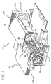
- Fig. 1 is a perspective view of a printer incorporating a first illustrative embodiment of a sheet feeding mechanism with the housing thereof partially removed.
- the printer 10 includes a housing assembly 12 which contains a paper control apparatus 15 and a printing assembly 20.
- the housing assembly 12 is comprised of a substantially rectangular base 14 having a pair of frame walls 18 projecting upwardly therefrom.
- a support (not shown) having a substantially L-shaped cross-sectional profile and a lip, extends between frame walls 18 and supports a supply assembly 30.
- the components of the paper control apparatus 15 and the printing assembly 20 are secured to the base 14, walls 18 and the support.
- a cover 16 is removably mounted to the base 14 to allow access to the interior thereof.
- a tray 34 containing a supply of paper, or other print medium, in a stack 32 is removably mounted within the printer 10.
- a receiving tray 36 is secured to the base 14. The receiving tray 36 projects outwardly from an aperture in front of the cover 16 for receiving printed sheets of paper.
- Each sheet of paper is moved by the paper control apparatus 15 through a printing zone where the print assembly 20 deposits ink on the paper as it advances toward a receiving tray 36.
- the print assembly 20 includes a printhead carriage 22 which travels back and forth on a carriage rod 23 through the printing zone.
- the printhead carriage 22 moves bidirectionally by means of a drive wire 24 coupled to a carriage motor by drive wire spools 29, in a manner well known to those skilled in the art.
- the printhead carriage 22 includes one or more print cartridges (not shown) having printheads at the bottom thereof.
- the printhead cartridges are connected by a flexible electrical interconnect strip 26 to a microprocessor 130, shown in phantom in Fig. 1.
- the microprocessor 130 controls a carriage motor (not shown).
- a control panel 27 is electrically coupled with the microprocessor 130 for selection of various options relating to the operation of the print assembly 20.
- Such control operations are provided by presently available microprocessors as is well known in the art.
- the structure and operation of the print assembly 20 forms no part of the present described embodiment and, accordingly, will not be described in further detail hereinafter.
- the microprocessor 130 is shown in the proximity of the control panel 27 in Fig. 1, it will be obvious to those reasonably skilled in the art that the microprocessor 130 may be positioned at other locations within the housing 12 provided that the necessary electrical connections may be made to the other elements of the printer 10.
- the paper control apparatus 15 includes first and second pick tires 66 and 68 for picking a single sheet of paper from the stack 32 and a kicker mechanism 70 for resetting the stack 32 thereafter to an initialized state.
- the kicker mechanism 70 is disclosed with respect to several illustrative embodiments.
- Figs. 1, 2a - 2d, and 3 provide simplified side views of the first illustrative embodiment of the disclosed kicker mechanism 70 in various stages of the operational cycle thereof.
- Fig. 3 is a simplified frontal view of the first illustrative embodiment of the kicker mechanism.
- the kicker mechanism 70 includes a kicker cam 72 mounted on a pick shaft 64 between the first and second pick tires 66 and 68 respectively.
- the kicker cam 72 has a crescent-like, semi-circular D-shape.
- the kicker cam 72 may be made of plastic or other suitable material.
- the cam 72 has a protrusion 73 at a first end of a cam surface adapted to engage a kicker 76.
- the cam surface has a generally arcuate shape to a second end 74.
- the arcuate shape of the cam surface facilitates an un-impeded return of the kicker 76 to its home position when the kicker cam 72 has rotated to a position at which the kicker 76 is no longer in contact therewith, i.e., at the second end of the cam surface 74.
- the kicker 76 is a piece of plastic of a substantially planar construction. At the proximal end thereof the kicker is generally U-shaped with upwardly extending portions 77 and 79 providing a trough 78 therebetween. The trough 78 is adapted to engage the kicker cam 72 during a portion of its rotational cycle. The upwardly extending portions 77 and 79 engage and reset media on the stack 32 as discussed more fully below.
- the kicker 76 is pivotally mounted to a frame, base or other rigid structure in the printer at a pivot point 75 and it is biased by a spring 80. One end of the spring 80 is connected to a distal end of the kicker 76 and the other end of the spring 80 is secured to the housing assembly 12.
- a separator pad 82 moves up and down under the influence of a second spring 84 to ensure an adequate separation force is applied to the media as it is drawn off the stack 32 by the pick tires 66 and 68. (See Fig. 3.)
- the stack 32 is also biased upward by a third spring 86.
- Fig. 2a depicts the first embodiment of the kicker mechanism 70 in a home position with the kicker 76 biased forward by a kicker spring 80.
- the pick tires 66 and 68 and the kicker cam 72 begin to rotate.
- Fig. 2b depicts the first embodiment of the kicker mechanism 70 after initiation of a pick cycle.
- the kicker cam 72 has pushed the kicker 76 back to a second position to allow sheets of paper to make contact with the pick tires 66 and 68 (not shown in Figs. 2a - 2d.)
- the stack of paper 32 has been allowed to rise to meet the pick tires 66 and 68 under the influence of the spring 86 by a conventional stack height control cam mechanism (not shown) operating off of the shaft 64.
- the separator pad 82 has been pushed down by the pick tires 66 and 68.
- the periphery of the cam 72 maintains the kicker 76 in the second position.
- the pick tires have a coefficient of friction (e.g., ⁇ 1.6 with paper) effective to cause the paper to move as the tires rotate thereover as is well known in the art.
- the separator pad 82 has a coefficient of friction with paper of ⁇ 1.0 typically and thereby assists in the extraction of a single sheet from the stack 32.
- Fig. 2c depicts the first embodiment of the kicker mechanism 70 as the sheet of paper moves over the kicker 76 to be picked up by a feed roll.
- the pick tires 66 and 68 and the kicker cam 72 continue to rotate counter clock-wise and the stack of paper 32 is lowered by the stack height control cam mechanism (not shown).
- the kicker 76 will remain pushed back by the cam 72 until the single sheet passes over it completely.
- the kicker cam 72 rotates past the point at which the end 74 is in contact with the kicker 76.
- the kicker 76 under load of the kicker spring 80, pushes any sheets of paper that remain on the separator pad 82 back onto the stack of paper 32.
- Fig. 2d depicts the first embodiment of the kicker mechanism 70 with all parts back in the home position. The mechanism 70 is then in its initial state with the kicker cam 72 and the kicker 76 in the home position.
- Fig. 2a While the embodiment of Fig. 2a is particularly well suited for horizontal stacks of media, the second embodiment of Figs. 4 and 5 is designed for use with an inclined stack of media.
- the reason for inclining the stack 32 is to reduce the footprint of the printer 10.
- many more sheets remain on the separator pad 82 due to the force of gravity.
- Fig. 4 is a perspective view of a printer incorporating a second illustrative embodiment of a sheet feeding mechanism with the housing thereof partially removed. Note that the mechanism is essentially identical to that of Fig. 1 with the exception that the supply tray 34 is inclined relative to the housing assembly 12 and the kicker mechanism 70' differs from the kicker mechanism 70 of Fig. 1 as discussed more fully below.
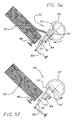
- Figs. 5a - 5f provide simplified side views of the second illustrative embodiment of a kicker mechanism 70' in various stages of the operational cycle thereof.
- the second embodiment of the kicker is similar to the first with the difference being the extension of the second end 74' of the cam surface.
- the operation of the second embodiment of the kicker mechanism 70' is the same as that of the first embodiment 70 as illustrated in Figs. 5a - 5d.
- the kicker cam 72' is counter-rotated as shown in Fig. 5e and the extended second end 74' of the cam 72' pushes back against the kicker 76' forcing it up against the stack 32.
- the mechanism 70' is shown in the home position.
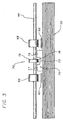
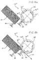
- Figs. 6a - 6d provide simplified side views of the inventive kicker mechanism 70" in various stages of the operational cycle thereof.
- Fig. 7 is a front view of the inventive kicker mechanism 70".
- This design is a counter rotating roll design that uses staggered and nested rolls to achieve separation.
- the use of counter-rotating rolls in automatic sheet feeders is a fairly common concept.
- the chief problems with the use of counter-rotating rolls is that the force between the rolls is hard to maintain within a certain range and a torque limiter must be used if the torque at the motor is to be kept low for high speed operation.
- kickers are not employed in these systems due to geometry constraints notwithstanding the potential for improved reliability associated with the use of same.
- the inventive kicker mechanism 70" includes a separator roll 72" mounted between the first and second 'D' shaped pick tires 66 and 68.
- the separator roll 72" is made of plastic and has a coefficient of friction with paper of approximately 1.0.
- First and second flexible kickers 76" and 77" are positioned on a kicker shaft 65" with the separator roll 72" outside of the first and second pick tires 66 and 68 as depicted in phantom in the frontal view of Fig. 7.
- the flexible kickers 76" and 77” are made of mylar or other suitable material and are approximately 0.4 mm thick. Each kicker 76" and 77" is made long enough to effectively reset the stack 32 as discussed more fully below.
- the kicker is made to be flexible so that the stack of paper can be located under the pick tires.
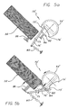
- Fig. 6a shows the mechanism 70" in its home position and initialized.
- the pick tires 66 and 68 and the separator roll 72" are rotated exactly one revolution per pick cycle.
- the paper stack is raised and presented to the pick tires at the beginning of the cycle and lowered before its completion.
- Fig. 6b shows the pick tires 66 and 68 rotating counter-clockwise and pulling the top few sheets from the raised stack into the separation zone.
- the separator roll 72" is rotating counter-clockwise which keeps all but the top sheet 33 from getting past the kickers 76" and 77". This causes the flexible kickers 76" and 77" to bend down and out of the way.
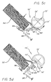
- Fig. 6c shows the stack 32, which has been lowered and the pick tires 66 and 68 and the separator roll 72" continuing to rotate in the same direction.
- the flexible kickers 76" and 77" are bent back by the single sheet 33 as it passes thereover while the separator roll 72" continues to prevent the feeding of extra sheets.
- Fig. 6d shows all components back in the home position.
- the kickers 76" and 77" once released by the single sheet straightens out and pushes excess sheets from the separation zone and back onto the stack and into an initialized position.
- the sheet of paper 33 is used as a separator spring as it bends around the rolls. This allows for the elimination of the expensive torque limiter and tight tolerances associated with the separator force. Also, because there is no torque limiter on the separating roll, a flexible kicker may be used to clear the separation zone. This allows the paper stack to be at an incline, which reduces the machine's footprint as mentioned above.
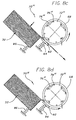
- Figs. 8a - 8f show simplified side views of a third illustrative embodiment of a kicker mechanism 70''' in various stages of the operational cycle thereof
- Fig. 9 is a front view of the third illustrative embodiment of the disclosed kicker mechanism 70"'.
- the kicker mechanism 70"' includes first and second kicker tires 72"' and 73"' mounted on a pick shaft 64 between first and second pick tires 66 and 68.
- a plurality of plastic kicker elements 76"' are positioned between the first and second kicker tires 72"' and 73"'.
- Each kicker element is a blade mounted for pivotal movement about a pin 81"' and is free to fall under the influence of gravity until it contacts a motion limiter 79"'.
- the motion limiters 79"' are pegs, pins or bumps of plastic or metal positioned to limit the range of motion of the kicker 76''' as illustrated in Figs. 8a - f.
- Fig. 8a shows the kicker mechanism 70''' in a starting position. There is no home position for this implementation.
- the kickers 76''' rotate off center and get pushed up and out of the way when the shaft 64 rotates counter-clockwise (as shown in Figs. 8a - d) and drop down to push the paper when the shaft is rotating clockwise (as shown in Figs. 8e and f).
- the separator pad 82 moves up and down to ensure an adequate separation force and is biased upward with a spring 84.
- the stack 32 is also biased upward but it is raised at the start of the pick cycle and lowered prior to its completion.
- Fig. 8b shows the mechanism 70"' after starting the pick cycle.
- the sheets are pushing the kickers 76"' up and out of the way with the forward rotation.
- the stack of paper 32 has been allowed to rise to meet the pick tires 66 and 68 and the top few sheets have been drawn into the separation zone.
- Fig. 8c shows the shaft 64 rotated forward even farther and helps to describe the motion of the kickers 76'''.
- Fig. 8d shows the mechanism 70''' after the top sheet has been completely fed.
- Fig. 8e shows the kicker tire 72''' reversing direction and the kickers 76''' dropping down to push the paper out of the separation zone.
Landscapes
- Engineering & Computer Science (AREA)
- Mechanical Engineering (AREA)
- Sheets, Magazines, And Separation Thereof (AREA)
Applications Claiming Priority (3)
| Application Number | Priority Date | Filing Date | Title |
|---|---|---|---|
| US08/715,683 US5882004A (en) | 1996-09-18 | 1996-09-18 | Automatic sheet feeding mechanism |
| US715683 | 1996-09-18 | ||
| EP97306868A EP0845429B1 (en) | 1996-09-18 | 1997-09-04 | Automatic sheet feeding mechanism |
Related Parent Applications (1)
| Application Number | Title | Priority Date | Filing Date |
|---|---|---|---|
| EP97306868A Division EP0845429B1 (en) | 1996-09-18 | 1997-09-04 | Automatic sheet feeding mechanism |
Publications (2)
| Publication Number | Publication Date |
|---|---|
| EP1199268A1 EP1199268A1 (en) | 2002-04-24 |
| EP1199268B1 true EP1199268B1 (en) | 2004-07-28 |
Family
ID=24875075
Family Applications (3)
| Application Number | Title | Priority Date | Filing Date |
|---|---|---|---|
| EP02075141A Expired - Lifetime EP1199268B1 (en) | 1996-09-18 | 1997-09-04 | Automatic sheet feeding mechanism |
| EP97306868A Expired - Lifetime EP0845429B1 (en) | 1996-09-18 | 1997-09-04 | Automatic sheet feeding mechanism |
| EP02075142A Expired - Lifetime EP1205412B1 (en) | 1996-09-18 | 1997-09-04 | Automatic sheet feeding mechanism |
Family Applications After (2)
| Application Number | Title | Priority Date | Filing Date |
|---|---|---|---|
| EP97306868A Expired - Lifetime EP0845429B1 (en) | 1996-09-18 | 1997-09-04 | Automatic sheet feeding mechanism |
| EP02075142A Expired - Lifetime EP1205412B1 (en) | 1996-09-18 | 1997-09-04 | Automatic sheet feeding mechanism |
Country Status (4)
| Country | Link |
|---|---|
| US (2) | US5882004A (enExample) |
| EP (3) | EP1199268B1 (enExample) |
| JP (1) | JP3893199B2 (enExample) |
| DE (3) | DE69723401T2 (enExample) |
Families Citing this family (53)
| Publication number | Priority date | Publication date | Assignee | Title |
|---|---|---|---|---|
| US6059281A (en) * | 1996-10-03 | 2000-05-09 | Canon Kabushiki Kaisha | Sheet feeding apparatus |
| DE69719282T2 (de) * | 1996-10-22 | 2003-11-13 | Seiko Epson Corp., Tokio/Tokyo | Blattzuführvorrichtung |
| JPH11310341A (ja) * | 1998-04-28 | 1999-11-09 | Oki Data Corp | プリンタの給紙装置及び給紙方法 |
| US6332608B1 (en) * | 1999-01-06 | 2001-12-25 | Canon Kabushiki Kaisha | Sheet feeding apparatus |
| US6257569B1 (en) * | 1999-02-24 | 2001-07-10 | Hewlett-Packard Company | Apparatus and method for delivery of sheet media to a printer |
| JP2003520168A (ja) * | 2000-01-19 | 2003-07-02 | サジェム エス アー | 印刷用記録担体のスタックを再整列させる手段を有する装置 |
| JP3680312B2 (ja) * | 2000-05-31 | 2005-08-10 | セイコーエプソン株式会社 | 給紙装置 |
| US6874778B2 (en) * | 2000-10-31 | 2005-04-05 | Canon Kabushiki Kaisha | Sheet feeding apparatus and image forming apparatus provided with same |
| US6457707B1 (en) | 2000-11-22 | 2002-10-01 | Hewlett-Packard Co. | Automatic document feeder |
| US6632061B2 (en) | 2001-03-30 | 2003-10-14 | Hewlett-Packard Development Company, L.P. | Booklet maker with sheet wise trim |
| US6824132B2 (en) * | 2001-05-10 | 2004-11-30 | Canon Kabushiki Kaisha | Sheet feeding apparatus and recording apparatus |
| US6896253B2 (en) * | 2001-05-10 | 2005-05-24 | Canon Kabushiki Kaisha | Sheet material feeding apparatus and recording apparatus |
| US20030095722A1 (en) * | 2001-11-19 | 2003-05-22 | Regimbal Laurent A. | Method and apparatus to detect and compensate for skew in a printing device |
| US6796556B2 (en) | 2002-02-11 | 2004-09-28 | Lexmark International, Inc. | Multi-function media eject system in an ink jet printer |
| US6637742B2 (en) | 2002-02-11 | 2003-10-28 | Lexmark International, Inc. | Multi-function media eject system in an ink jet printer |
| US7040614B2 (en) * | 2002-02-18 | 2006-05-09 | Canon Kabushiki Kaisha | Sheet feeding device and recording apparatus |
| US6663098B2 (en) * | 2002-04-25 | 2003-12-16 | Hewlett-Packard Development Company, L.P. | Compound kicker in media handling system |
| US7165765B2 (en) * | 2002-06-07 | 2007-01-23 | Canon Kabushiki Kaisha | Sheet feeding apparatus and recording apparatus |
| JP2004035229A (ja) * | 2002-07-05 | 2004-02-05 | Sharp Corp | シート給送装置 |
| JP2004083202A (ja) * | 2002-08-27 | 2004-03-18 | Matsushita Electric Ind Co Ltd | 分離給紙装置 |
| US6832862B2 (en) | 2003-02-28 | 2004-12-21 | Eastman Kodak Company | System for opening and closing a resealable cartridge |
| CN1307057C (zh) * | 2003-07-15 | 2007-03-28 | 明基电通股份有限公司 | 记录媒体馈送系统及方法 |
| US7197971B2 (en) | 2003-07-18 | 2007-04-03 | Hewlett-Packard Development Company, L.P. | Device for trimming sheet material |
| TWM242504U (en) * | 2003-11-13 | 2004-09-01 | Benq Corp | A sheet-feeding apparatus |
| US7100914B2 (en) * | 2004-01-15 | 2006-09-05 | Hewlett-Packard Development Company, L.P. | Sheet media input |
| US7267334B2 (en) * | 2004-06-03 | 2007-09-11 | Hewlett-Packard Development Company, L.P. | Active media kicker system |
| JP4378229B2 (ja) * | 2004-06-14 | 2009-12-02 | キヤノン株式会社 | 自動給送装置及び記録装置 |
| JP2006117391A (ja) | 2004-10-21 | 2006-05-11 | Seiko Epson Corp | 媒体給送装置の駆動方法、駆動制御プログラム及び記録装置 |
| US7300049B2 (en) * | 2005-01-12 | 2007-11-27 | Pitney Bowes Ltd. | Feed of sheet material in a feeder/separator |
| US20060255528A1 (en) * | 2005-05-13 | 2006-11-16 | Kyocera Mita Corporation | Sheet separating/conveying mechanism and sheet conveying apparatus therewith |
| US7549633B2 (en) * | 2005-09-15 | 2009-06-23 | Canon Kabushiki Kaisha | Sheet conveying apparatus, image recording apparatus, and image reading apparatus |
| JP2007137559A (ja) * | 2005-11-16 | 2007-06-07 | Ricoh Co Ltd | 給紙装置 |
| US7513495B2 (en) * | 2005-12-13 | 2009-04-07 | Hewlett-Packard Development Company, L.P. | Separator |
| US7852526B2 (en) * | 2006-04-28 | 2010-12-14 | Hewlett-Packard Development Company, L.P. | Separator |
| JP4720611B2 (ja) * | 2006-05-15 | 2011-07-13 | 富士ゼロックス株式会社 | シート供給装置および画像形成装置 |
| US7665724B2 (en) * | 2007-03-08 | 2010-02-23 | Hewlett-Packard Development Company, L.P. | Kicker |
| TWI318930B (en) * | 2007-06-15 | 2010-01-01 | Primax Electronics Ltd | Document-feeding apparatus with improved sheet-separating structure |
| JP4826812B2 (ja) * | 2007-06-20 | 2011-11-30 | セイコーエプソン株式会社 | 給送装置、記録装置 |
| KR20090006303A (ko) * | 2007-07-11 | 2009-01-15 | 삼성전자주식회사 | 키킹유닛 및 이를 포함하는 화상형성장치 |
| US8360414B2 (en) * | 2007-10-15 | 2013-01-29 | Hewlett-Packard Development Company, L.P. | Imaging device |
| US8910932B2 (en) | 2011-06-30 | 2014-12-16 | Hewlett-Packard Development Company, L.P. | Separator assembly for use with printers |
| PL2731896T3 (pl) * | 2011-07-13 | 2016-01-29 | Essity Hygiene & Health Ab | Dozownik oraz stos produktów arkuszowych |
| JP2013220862A (ja) * | 2012-04-12 | 2013-10-28 | Sumitomo Rubber Ind Ltd | 紙葉類分離パッドおよび画像形成装置 |
| JP6188493B2 (ja) * | 2012-08-30 | 2017-08-30 | キヤノン株式会社 | 給送装置及び記録装置 |
| JP6089562B2 (ja) * | 2012-10-11 | 2017-03-08 | ブラザー工業株式会社 | シート供給装置 |
| RU2616564C2 (ru) | 2012-10-26 | 2017-04-17 | Ска Хайджин Продактс Аб | Разделительный блок, а также раздаточное устройство, содержащее разделительный блок |
| CN104755001B (zh) * | 2012-10-26 | 2017-08-08 | Sca卫生用品公司 | 分离单元和包括分离单元的分配器 |
| CN112386151A (zh) | 2012-10-26 | 2021-02-23 | 易希提卫生与保健公司 | 分配器 |
| JP6136893B2 (ja) * | 2013-11-27 | 2017-05-31 | ブラザー工業株式会社 | 画像形成装置 |
| PL3136926T3 (pl) | 2014-04-28 | 2022-11-14 | Essity Hygiene And Health Aktiebolag | Dozownik |
| US9302866B1 (en) * | 2015-02-24 | 2016-04-05 | Lexmark International, Inc. | Pick mechanism pick roll tire having multiple tread widths |
| JP6924369B2 (ja) * | 2017-05-30 | 2021-08-25 | セイコーエプソン株式会社 | 記録装置 |
| US20230382665A1 (en) * | 2020-10-29 | 2023-11-30 | Hewlett-Packard Development Company, L.P. | Tray to hold sheet media for printing |
Family Cites Families (15)
| Publication number | Priority date | Publication date | Assignee | Title |
|---|---|---|---|---|
| US3601394A (en) * | 1969-07-03 | 1971-08-24 | Xerox Corp | Sheet retaining apparatus |
| DE3166483D1 (en) * | 1980-09-08 | 1984-11-08 | Agfa Gevaert Nv | Dispenser for dispensing photographic sheets from a stack |
| JPS58109334A (ja) * | 1981-12-21 | 1983-06-29 | Minolta Camera Co Ltd | シ−ト給送装置 |
| GB2126993B (en) * | 1982-09-21 | 1986-08-13 | Xerox Corp | Separating sheets from a tray |
| US4541623A (en) * | 1982-12-27 | 1985-09-17 | International Business Machines Corporation | Alignment restraint station |
| JPH0742003B2 (ja) * | 1988-11-28 | 1995-05-10 | 三田工業株式会社 | 画像形成装置の重送防止給紙装置 |
| JPH02221039A (ja) * | 1989-02-17 | 1990-09-04 | Minolta Camera Co Ltd | シート給送装置 |
| US5026042A (en) * | 1990-01-22 | 1991-06-25 | Xerox Corporation | Sheet feeder for copiers and printers |
| US5226743A (en) * | 1991-04-16 | 1993-07-13 | Hewlett-Packard Company | Method and apparatus for paper control in a printer |
| DE69227551T2 (de) * | 1991-08-21 | 1999-05-27 | Canon K.K., Tokio/Tokyo | Automatischer Apparat zum Zuführen von Blättern |
| JP2512258B2 (ja) * | 1992-03-11 | 1996-07-03 | 松下電器産業株式会社 | シ―ト給送装置 |
| US5316285A (en) * | 1993-04-30 | 1994-05-31 | Hewlett-Packard Company | Sheet media realignment mechanism |
| JP3822652B2 (ja) * | 1994-04-26 | 2006-09-20 | ブラザー工業株式会社 | 用紙搬送装置 |
| US5520381A (en) * | 1994-07-21 | 1996-05-28 | Genesis Technology, Inc. | High capacity, low jam envelope feeder for laser printer |
| JP3320982B2 (ja) * | 1996-07-09 | 2002-09-03 | 京セラミタ株式会社 | 給紙装置 |
-
1996
- 1996-09-18 US US08/715,683 patent/US5882004A/en not_active Expired - Lifetime
-
1997
- 1997-09-04 DE DE69723401T patent/DE69723401T2/de not_active Expired - Fee Related
- 1997-09-04 EP EP02075141A patent/EP1199268B1/en not_active Expired - Lifetime
- 1997-09-04 DE DE69728192T patent/DE69728192T2/de not_active Expired - Fee Related
- 1997-09-04 DE DE69730059T patent/DE69730059T2/de not_active Expired - Fee Related
- 1997-09-04 EP EP97306868A patent/EP0845429B1/en not_active Expired - Lifetime
- 1997-09-04 EP EP02075142A patent/EP1205412B1/en not_active Expired - Lifetime
- 1997-09-11 JP JP24702997A patent/JP3893199B2/ja not_active Expired - Fee Related
-
1998
- 1998-12-15 US US09/211,088 patent/US6082729A/en not_active Expired - Lifetime
Also Published As
| Publication number | Publication date |
|---|---|
| EP1199268A1 (en) | 2002-04-24 |
| DE69730059D1 (de) | 2004-09-02 |
| DE69723401D1 (de) | 2003-08-14 |
| DE69728192D1 (de) | 2004-04-22 |
| EP0845429A1 (en) | 1998-06-03 |
| EP1205412A1 (en) | 2002-05-15 |
| EP0845429B1 (en) | 2003-07-09 |
| DE69730059T2 (de) | 2005-09-01 |
| DE69723401T2 (de) | 2004-04-15 |
| JPH1087093A (ja) | 1998-04-07 |
| US5882004A (en) | 1999-03-16 |
| EP1205412B1 (en) | 2004-03-17 |
| US6082729A (en) | 2000-07-04 |
| JP3893199B2 (ja) | 2007-03-14 |
| DE69728192T2 (de) | 2005-01-27 |
Similar Documents
| Publication | Publication Date | Title |
|---|---|---|
| EP1199268B1 (en) | Automatic sheet feeding mechanism | |
| US6135444A (en) | Automatic sheet feeding mechanism | |
| EP0734875B1 (en) | Sheet supplying apparatus | |
| EP0609560B1 (en) | Sheet convey apparatus | |
| EP0509667B1 (en) | Method and apparatus for paper control and skew correction in a printer | |
| EP0658434A2 (en) | Method and apparatus for paper control and skew correction in a printer | |
| JP3468559B2 (ja) | 用紙取り出し係合器 | |
| JP3532298B2 (ja) | 印刷媒体つまみ装置 | |
| US4750726A (en) | Automatic document feeder/separator for copiers | |
| EP0104058B1 (en) | Record carrier feed arrangement for a printer | |
| JP3495932B2 (ja) | シート給送装置及び記録装置 | |
| US6146036A (en) | Rotatable cam device for a pickup roller of a printer | |
| US5810492A (en) | Printer and print start method therefore | |
| US7001017B2 (en) | Drive roller releasing apparatus for ink-jet printer | |
| US4750727A (en) | Automatic document feeder for copiers | |
| JPS6285972A (ja) | 印字装置 | |
| WO1988002735A1 (en) | Card feeding apparatus | |
| JP2801438B2 (ja) | 自動給紙装置及び記録装置 | |
| JPH042927Y2 (enExample) | ||
| JP3368151B2 (ja) | シート給送装置及び記録装置 | |
| KR100218000B1 (ko) | Dc모터를 이용한 잉크젯 프린터의 급지 에러 방지 장치 | |
| JPH0822607B2 (ja) | プリンタの紙送り機構 | |
| JP3363827B2 (ja) | 自動給送装置及びそれを用いた記録装置 | |
| EP1630114A2 (en) | Sheet feed device and image formation device | |
| JPH05208746A (ja) | 自動給紙装置及び記録装置 |
Legal Events
| Date | Code | Title | Description |
|---|---|---|---|
| PUAI | Public reference made under article 153(3) epc to a published international application that has entered the european phase |
Free format text: ORIGINAL CODE: 0009012 |
|
| AC | Divisional application: reference to earlier application |
Ref document number: 845429 Country of ref document: EP |
|
| AK | Designated contracting states |
Kind code of ref document: A1 Designated state(s): DE FR GB |
|
| 17P | Request for examination filed |
Effective date: 20021008 |
|
| AKX | Designation fees paid |
Free format text: DE FR GB |
|
| 17Q | First examination report despatched |
Effective date: 20030703 |
|
| GRAP | Despatch of communication of intention to grant a patent |
Free format text: ORIGINAL CODE: EPIDOSNIGR1 |
|
| GRAS | Grant fee paid |
Free format text: ORIGINAL CODE: EPIDOSNIGR3 |
|
| GRAA | (expected) grant |
Free format text: ORIGINAL CODE: 0009210 |
|
| AC | Divisional application: reference to earlier application |
Ref document number: 0845429 Country of ref document: EP Kind code of ref document: P |
|
| AK | Designated contracting states |
Kind code of ref document: B1 Designated state(s): DE FR GB |
|
| REG | Reference to a national code |
Ref country code: GB Ref legal event code: FG4D |
|
| REF | Corresponds to: |
Ref document number: 69730059 Country of ref document: DE Date of ref document: 20040902 Kind code of ref document: P |
|
| ET | Fr: translation filed | ||
| PLBE | No opposition filed within time limit |
Free format text: ORIGINAL CODE: 0009261 |
|
| STAA | Information on the status of an ep patent application or granted ep patent |
Free format text: STATUS: NO OPPOSITION FILED WITHIN TIME LIMIT |
|
| 26N | No opposition filed |
Effective date: 20050429 |
|
| PGFP | Annual fee paid to national office [announced via postgrant information from national office to epo] |
Ref country code: FR Payment date: 20060918 Year of fee payment: 10 |
|
| PGFP | Annual fee paid to national office [announced via postgrant information from national office to epo] |
Ref country code: DE Payment date: 20061031 Year of fee payment: 10 |
|
| PGFP | Annual fee paid to national office [announced via postgrant information from national office to epo] |
Ref country code: GB Payment date: 20070926 Year of fee payment: 11 |
|
| PG25 | Lapsed in a contracting state [announced via postgrant information from national office to epo] |
Ref country code: DE Free format text: LAPSE BECAUSE OF NON-PAYMENT OF DUE FEES Effective date: 20080401 |
|
| REG | Reference to a national code |
Ref country code: FR Ref legal event code: ST Effective date: 20080531 |
|
| PG25 | Lapsed in a contracting state [announced via postgrant information from national office to epo] |
Ref country code: FR Free format text: LAPSE BECAUSE OF NON-PAYMENT OF DUE FEES Effective date: 20071001 |
|
| GBPC | Gb: european patent ceased through non-payment of renewal fee |
Effective date: 20080904 |
|
| PG25 | Lapsed in a contracting state [announced via postgrant information from national office to epo] |
Ref country code: GB Free format text: LAPSE BECAUSE OF NON-PAYMENT OF DUE FEES Effective date: 20080904 |