EP1188022B1 - Systeme de combustion de carburant ameliore - Google Patents
Systeme de combustion de carburant ameliore Download PDFInfo
- Publication number
- EP1188022B1 EP1188022B1 EP00936093A EP00936093A EP1188022B1 EP 1188022 B1 EP1188022 B1 EP 1188022B1 EP 00936093 A EP00936093 A EP 00936093A EP 00936093 A EP00936093 A EP 00936093A EP 1188022 B1 EP1188022 B1 EP 1188022B1
- Authority
- EP
- European Patent Office
- Prior art keywords
- combustion
- gas feed
- mass fuel
- gas
- grate
- Prior art date
- Legal status (The legal status is an assumption and is not a legal conclusion. Google has not performed a legal analysis and makes no representation as to the accuracy of the status listed.)
- Expired - Lifetime
Links
Images


Classifications
-
- F—MECHANICAL ENGINEERING; LIGHTING; HEATING; WEAPONS; BLASTING
- F23—COMBUSTION APPARATUS; COMBUSTION PROCESSES
- F23N—REGULATING OR CONTROLLING COMBUSTION
- F23N1/00—Regulating fuel supply
- F23N1/02—Regulating fuel supply conjointly with air supply
- F23N1/022—Regulating fuel supply conjointly with air supply using electronic means
-
- F—MECHANICAL ENGINEERING; LIGHTING; HEATING; WEAPONS; BLASTING
- F23—COMBUSTION APPARATUS; COMBUSTION PROCESSES
- F23G—CREMATION FURNACES; CONSUMING WASTE PRODUCTS BY COMBUSTION
- F23G5/00—Incineration of waste; Incinerator constructions; Details, accessories or control therefor
- F23G5/002—Incineration of waste; Incinerator constructions; Details, accessories or control therefor characterised by their grates
-
- F—MECHANICAL ENGINEERING; LIGHTING; HEATING; WEAPONS; BLASTING
- F23—COMBUSTION APPARATUS; COMBUSTION PROCESSES
- F23G—CREMATION FURNACES; CONSUMING WASTE PRODUCTS BY COMBUSTION
- F23G5/00—Incineration of waste; Incinerator constructions; Details, accessories or control therefor
- F23G5/08—Incineration of waste; Incinerator constructions; Details, accessories or control therefor having supplementary heating
- F23G5/14—Incineration of waste; Incinerator constructions; Details, accessories or control therefor having supplementary heating including secondary combustion
-
- F—MECHANICAL ENGINEERING; LIGHTING; HEATING; WEAPONS; BLASTING
- F23—COMBUSTION APPARATUS; COMBUSTION PROCESSES
- F23G—CREMATION FURNACES; CONSUMING WASTE PRODUCTS BY COMBUSTION
- F23G5/00—Incineration of waste; Incinerator constructions; Details, accessories or control therefor
- F23G5/50—Control or safety arrangements
-
- F—MECHANICAL ENGINEERING; LIGHTING; HEATING; WEAPONS; BLASTING
- F23—COMBUSTION APPARATUS; COMBUSTION PROCESSES
- F23H—GRATES; CLEANING OR RAKING GRATES
- F23H17/00—Details of grates
-
- F—MECHANICAL ENGINEERING; LIGHTING; HEATING; WEAPONS; BLASTING
- F23—COMBUSTION APPARATUS; COMBUSTION PROCESSES
- F23H—GRATES; CLEANING OR RAKING GRATES
- F23H7/00—Inclined or stepped grates
- F23H7/06—Inclined or stepped grates with movable bars disposed parallel to direction of fuel feeding
- F23H7/08—Inclined or stepped grates with movable bars disposed parallel to direction of fuel feeding reciprocating along their axes
-
- F—MECHANICAL ENGINEERING; LIGHTING; HEATING; WEAPONS; BLASTING
- F23—COMBUSTION APPARATUS; COMBUSTION PROCESSES
- F23N—REGULATING OR CONTROLLING COMBUSTION
- F23N5/00—Systems for controlling combustion
- F23N5/003—Systems for controlling combustion using detectors sensitive to combustion gas properties
-
- F—MECHANICAL ENGINEERING; LIGHTING; HEATING; WEAPONS; BLASTING
- F23—COMBUSTION APPARATUS; COMBUSTION PROCESSES
- F23G—CREMATION FURNACES; CONSUMING WASTE PRODUCTS BY COMBUSTION
- F23G2202/00—Combustion
- F23G2202/10—Combustion in two or more stages
- F23G2202/106—Combustion in two or more stages with recirculation of unburned solid or gaseous matter into combustion chamber
-
- F—MECHANICAL ENGINEERING; LIGHTING; HEATING; WEAPONS; BLASTING
- F23—COMBUSTION APPARATUS; COMBUSTION PROCESSES
- F23G—CREMATION FURNACES; CONSUMING WASTE PRODUCTS BY COMBUSTION
- F23G2202/00—Combustion
- F23G2202/40—Combustion in a pulsed combustion chamber
-
- F—MECHANICAL ENGINEERING; LIGHTING; HEATING; WEAPONS; BLASTING
- F23—COMBUSTION APPARATUS; COMBUSTION PROCESSES
- F23G—CREMATION FURNACES; CONSUMING WASTE PRODUCTS BY COMBUSTION
- F23G2203/00—Furnace arrangements
- F23G2203/107—Furnace arrangements with vibrating grate
-
- F—MECHANICAL ENGINEERING; LIGHTING; HEATING; WEAPONS; BLASTING
- F23—COMBUSTION APPARATUS; COMBUSTION PROCESSES
- F23G—CREMATION FURNACES; CONSUMING WASTE PRODUCTS BY COMBUSTION
- F23G2207/00—Control
- F23G2207/10—Arrangement of sensing devices
- F23G2207/101—Arrangement of sensing devices for temperature
-
- F—MECHANICAL ENGINEERING; LIGHTING; HEATING; WEAPONS; BLASTING
- F23—COMBUSTION APPARATUS; COMBUSTION PROCESSES
- F23G—CREMATION FURNACES; CONSUMING WASTE PRODUCTS BY COMBUSTION
- F23G2207/00—Control
- F23G2207/10—Arrangement of sensing devices
- F23G2207/114—Arrangement of sensing devices for combustion bed level
-
- F—MECHANICAL ENGINEERING; LIGHTING; HEATING; WEAPONS; BLASTING
- F23—COMBUSTION APPARATUS; COMBUSTION PROCESSES
- F23G—CREMATION FURNACES; CONSUMING WASTE PRODUCTS BY COMBUSTION
- F23G2207/00—Control
- F23G2207/20—Waste supply
-
- F—MECHANICAL ENGINEERING; LIGHTING; HEATING; WEAPONS; BLASTING
- F23—COMBUSTION APPARATUS; COMBUSTION PROCESSES
- F23G—CREMATION FURNACES; CONSUMING WASTE PRODUCTS BY COMBUSTION
- F23G2207/00—Control
- F23G2207/30—Oxidant supply
-
- F—MECHANICAL ENGINEERING; LIGHTING; HEATING; WEAPONS; BLASTING
- F23—COMBUSTION APPARATUS; COMBUSTION PROCESSES
- F23G—CREMATION FURNACES; CONSUMING WASTE PRODUCTS BY COMBUSTION
- F23G2900/00—Special features of, or arrangements for incinerators
- F23G2900/55—Controlling; Monitoring or measuring
- F23G2900/55009—Controlling stoker grate speed or vibrations for waste movement
-
- F—MECHANICAL ENGINEERING; LIGHTING; HEATING; WEAPONS; BLASTING
- F23—COMBUSTION APPARATUS; COMBUSTION PROCESSES
- F23N—REGULATING OR CONTROLLING COMBUSTION
- F23N2225/00—Measuring
- F23N2225/08—Measuring temperature
- F23N2225/16—Measuring temperature burner temperature
-
- F—MECHANICAL ENGINEERING; LIGHTING; HEATING; WEAPONS; BLASTING
- F23—COMBUSTION APPARATUS; COMBUSTION PROCESSES
- F23N—REGULATING OR CONTROLLING COMBUSTION
- F23N2237/00—Controlling
- F23N2237/16—Controlling secondary air
-
- F—MECHANICAL ENGINEERING; LIGHTING; HEATING; WEAPONS; BLASTING
- F23—COMBUSTION APPARATUS; COMBUSTION PROCESSES
- F23N—REGULATING OR CONTROLLING COMBUSTION
- F23N2241/00—Applications
- F23N2241/18—Incinerating apparatus
-
- F—MECHANICAL ENGINEERING; LIGHTING; HEATING; WEAPONS; BLASTING
- F23—COMBUSTION APPARATUS; COMBUSTION PROCESSES
- F23N—REGULATING OR CONTROLLING COMBUSTION
- F23N5/00—Systems for controlling combustion
- F23N5/16—Systems for controlling combustion using noise-sensitive detectors
Definitions
- This invention is primarily directed to an improved stationary combustion apparatus designed to utilize solid fuel such as household and industrial waste, it will be understood that any of various types of combustible, particulate materials may serve as the supply fuel feed for the instant apparatus.
- mass fuel referred to herein, is intended to mean any matter being combusted while resting on a surface or traveling on or along a surface. This might be distinguished from methods in which the matter is purposefully suspended in air a substantial distance above a surface. It might also be distinguished from methods, which require the matter to be fragmented before combustion.
- Mass fuel applications for which this invention may be utilized include, but are not limited to elastomeric products, coal, waste coal, sewage sludge, biomass products, municipal solid waste, industrial waste, infectious waste, and manure.
- this invention relates to combustion systems which may be utilized as an apparatus.
- the invention is intended to provide an improved technique for efficiently combusting a mass fuel, possibly having widely varying combustion characteristics, upon a grate assembly in an incinerator or furnace.
- the combustion system is designed specifically to be an improvement over current incinerator or combustion grate assemblies and current methods of combusting a mass fuel.
- One known method of burning or combusting refuse incorporates the use of a combustion grate for supporting the fuel during combustion.
- the method can be directed at dividing the combustion grate into two or three separate treatment zones and, through plenum or supply chambers, may provide combustion air under differing parameters to each one, varying the characteristics of the air to suit the combustion needs.
- the air in the first zone containing fresh, un-bumed refuse may be heated to dry out the trapped moisture, with combustion possibly not commencing until the refuse has entered the next zone, which may be supplied with a different air mix.
- the control of combustion in various zones has sometimes been thought to be limited to varying the characteristics of the air flowing to each zone. However, as the thickness of the refuse layer and its combustion characteristics may not be uniform across any one zone, burning time may be longer, possibly dictated by the slowest burning area on the grate.
- the control could optimally be as automatic as possible, so that each zone can be monitored and adjusted continuously, in an effort to maximize the efficiency of the burning to obtain the greatest throughput of fuel.
- the throughput of fuel may include the disposal through combustion of an input feed material, and or in the alternative, the production of a source of energy, such as heated air, water or steam from the burning operation.
- Optimal burn or combustion efficiency may be achieved by simultaneously mixing or agitating the mass fuels and burning or combustion.
- simultaneous steps of agitating and combusting of mass fuels may have been previously performed in prior combustion techniques
- the overall objective of agitating and combusting may be performed in a variety of systems to further optimize combustion efficiency.
- One system often available for performing mass fuel agitation prior to the present invention appears to provide a stepped combustion grate, whereby a part or all of the steps move in a fashion which apparently aids in the overall mixing and travel of the fuel in a predominant direction.
- a system to accomplish the mixing or agitation of mass fuel may provide combustion air being fed through the grate assembly as the source of agitation.
- combustion air for the dual purpose of combustion and agitation presents additional problems of system optimization.
- the use of one controlled air source for combustion as well as fuel agitation may not allow for the optimization of either the combustion or the agitation.
- the system may maintain the required combustion air flow to support the overall combustion process.
- the specific requirements needed for the agitation may be neglected.
- the system may maintain the requirements needed to perform the agitation of the fuel.
- the necessary requirements for the proper oxygen-to-fuel ratio for combustion may be neglected either with too much or too little air.
- the above referenced patents may also not have optimally provided for the efficient control of combustion parameters apart from combustion air and mix air control.
- Other system parameters may be monitored and controlled to further enhance the combustion efficiency. It would be desirable, then, to monitor and control the combustion system based upon system parameters, such as, by way of example and not of limitation, combustion chamber temperature, oxygen content of chamber air, carbon monoxide content of chamber air, and mass fuel feed rate, among others.
- the use of combusted air from the process may be used to further enhance system parameters such as, again by way of example and not of limitation, recycled air for combustion chamber temperature control.
- System parameters may further be optimized by a particular coordination of air introduction within the combustion system. It is desirable, therefore, to provide a combustion system that can monitor and control combustion parameters of the system and can optimize the parameters through the efficient use and introduction of multiple air sources.
- agglomerated combustion by-product or perhaps even slag may form within combustion systems resulting from the spent or combusted mass fuel accumulating within the system.
- WO-A1-9701433 discloses an incinerator in a fluidized bed of granular material that circulates in a combustion chamber to which air may be added in pulsed fashion.
- US-A-5,762,008 discloses an incinerator in which oxygen content levels of air inserted into the incinerator are manipulated to improve combustion.
- DE-U-8702507 discloses an incinerator with jets arranged in linear fashion through which air is forced to improve combustion, or enable better control over it.
- the present invention provides a combustion system that addresses the inadequacies that may have existed with prior incineration or combustion systems. Accordingly, the present invention provides a mass fuel combustion furnace for combusting a mass fuel.
- a combustion system for combusting a mass fuel that improves the speed of response and flexibility in the control of combustion of mass fuels.
- a goal of the present invention therefore can be to provide a combustion system that injects a secondary agitation gas into the fuel mass which can lift, agitate, dry and control the migration of the fuel during the combustion process.
- a goal of the present invention therefore is to provide a combustion system that allows the grate to be "stationary" to a large degree.
- a goal of the present invention therefore is to provide a combustion system that limits the addition of significant excess oxygen, such as atmospheric air in the fuel introduction system.
- Yet another object of the present invention may be to provide a combustion system for combusting a mass fuel that provides for agitation gas injection with a plurality of injection points and to independently control the rate of delivery of the gas flow at each point.
- a goal of the present invention therefore is to provide a combustion system with control of the velocity or flow of the mix gas at each point where it is released into the fuel and to provide a force available for performing the tasks of mixing, drying and controlling the migration rate of the material.
- a goal of the present invention therefore is to provide a combustion system that optimizes agitation gas introduction defined by the particular grate plates.
- Still another object of the present invention is to provide a combustion system that minimizes variations in heat release rates during the combustion process.
- a goal of the present invention therefore is to provide a combustion system that controls the fuel feed rate to the combustion process.
- a goal of the present invention therefore is to provide a combustion system that efficiently provides for the removal of ash and agglomerated combustion by-product.
- a goal of the present invention therefore is to provide a combustion system that monitors and optimizes parameters within the system.
- a goal of the present invention therefore is to provide a combustion system with multiple treatment zones, each zone having a separate introduction of combustion and agitation gases, independent rate control of delivery of combustion and agitation gas and separate agglomerated combustion by-product reduction method.
- Another object of the present invention is to provide a combustion system for combusting a mass fuel that provides control of the temperatures on the combustion grate surface and throughout the combustion process.
- a goal of the present invention therefore is to provide a combustion system using exhaust gas, agitation gas and other types of control.
- mass fuel or solid fuel
- mass fuel applications in which this invention may be utilized may include, but are not limited to, elastomeric products, coal, waste coal, sewage sludge, biomass products, municipal solid waste, industrial waste, infectious waste, and manure.
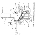
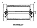
- FIG. 1 shows a partial cross-sectional and elevation view of one embodiment of a combustion system of the present invention.
- the combustion system of the present invention may relate to a furnace or incinerator, generally designated (10), which may be employed for the purpose of merely incinerating an input mass fuel for disposal or to generate a source of energy, such as hot air, heated water or steam.
- a furnace or incinerator generally designated (10)
- peripheral housing or walls (12) of the furnace may be configured in any suitable well-known manner according to the intended use of the furnace.
- the present invention may be directed to the design and configuration of a grate system or assembly (14) serving, in one embodiment of the present invention, to receive and dispose of mass fuel or other material (16) during a combustion process.
- Combustion process or “combustion system” refers generally to a system, inherently including methods and associated devices, for receiving a fuel and combusting the fuel to produce an energy release and to result in substantially combusted material, typically in the form of ash.
- by-products of the combustion process may include, but are not limited to, un-combusted material and agglomerated combustion by-product, or even slag (whether used in its technical or vernacular sense) generated by the combustion of mass fuel.
- the combustion process takes place substantially on the surface of the grate assembly (14).
- the suspension of un-combusted and combusting mass fuel is minimized in order to maintain complete and efficient combustion of all the supplied mass fuel from the mass fuel feed such as the vertical hopper assembly (18) and feed element or feed table (20).
- the grate system or assembly (14) can provide numerous advantages in the disclosed plurality of embodiments.
- One important advantage is that numerous types of particulate, solid or semi-solid materials, i.e. mass fuels as described supra, exhibiting a wide range of parameters, particularly combustion characteristics, are readily accommodated by the grate assembly (14) given the attendant features of the disclosed combustion system described in various embodiments below. Therefore, an optimum amount of combustion of the mass fuel fed into the system can occur with minimum ash and agglomerated combustion by-product remaining for disposal after or during combustion.
- the furnace (10) may further comprise generally, in a preferred embodiment, an upper combustion chamber (20) and a lower combustion chamber (22) where combustion of the mass fuels may preferably take place.
- An auxiliary burner (24) may also be provided to aid in the start-up and shut down of the combustion system.
- Combustion gas, and in a preferred embodiment combustion air can be provided to at least one combustion gas feed or plenums (26) via combustion gas plenum inlets (28).
- the combustion gas feeds (26) may alternatively or in combination serve as a siftings hopper for combusted mass fuel or ash and for agglomerated combustion by-product from the combusted mass fuel.
- combustion gas feeds may alternatively or in combination serve to receive recycled exhaust or combusted gas via plenum inlets (30) to help control combustion parameters, such as temperature or oxygen content as more particularly described below.
- Recycled exhaust or combusted gas may additionally be introduced into the combustion system via inlets (42).
- combustion gas may also be introduced through top or bottom combustion gas feeds. This is shown as the top feed embodiment through upper inlets (32).
- gas may be introduced via the various plenums (26) and inlets (28) (32) and (42) to provide a post-combustion gas feed to the combustion chambers.
- the introduction of post-combustion gas may serve a variety of purposes, including, but not limited to, the temperature regulation of the combustion chamber and the reduction of ash and agglomerated combustion by-product from the grate assembly and combustion chambers.
- Post-combustion gas introduction may be performed via a recycled combusted gas system wherein the post-combustion gas introduced may preferably be combusted gas.
- plenums (26) may serve to introduce gases other than combustion or recycled gases, depending on the particular demands of the combustion process, and may include introducing other gases, including, but not limited to, a second combustion gas, uncombustible gases, and grate-cooling gases, among others.
- Secondary or even agitation gas feeds (34) provide a secondary or agitation or mixing gas source such as for the agitation or mixing of mass fuel, as more fully described below.
- the secondary gas feeds may further provide, in preferred embodiments for the transportation of mass fuel from an inlet end of the grate assembly (14) near mass fuel feed elements (18) and (20) to an outlet end of the grate assembly near combusted mass fuel or discharge chute (36) and combusted mass fuel or ash conveyor (38).
- the secondary gas may serve to impart motion or lift to materials located on the grate assembly (14).
- the secondary or agitation gas feeds supply secondary gas to dry the materials located on the grate assembly.
- a mass fuel located upon the grate assembly may be mixed or agitated, dried and migrated along the grate assembly.
- the introduction and control of a secondary or an agitation gas to the grate system may be provided by gas poppets (44), more fully described below.
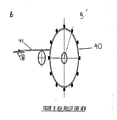
- An ash discharge system (39), preferably comprising an ash roller (40), can be provided at the outlet end of grate assembly (14).
- Ash discharge system (39) may also comprise a discharge chute (36) and removal conveyor (38).
- the ash roller may serve to control the depth of material on the grate and may further aid in the removal of the materials from the grate system, including, but not limited to, combusted and un-combusted mass fuel, ash, and agglomerated combustion by-product.
- the ash roller may additionally or alternatively serve to insure the desired or appropriate level of material, particularly that of mass fuel, in the combustion system.
- Ash roller (40) may, therefore, be adjustable to provide for the control of material removal from or of mass fuel level upon the grate assembly (14).
- an embodiment of the ash roller can comprise a pivotal plate (41) adjacent the ash roller to aid in the removal of ash and to further control the level of mass fuel upon the grate assembly.
- the conveyor (38) may be filled with water to prevent the undesired introduction of air into the combustion chamber through the ash discharge chute, among other purposes.
- an access door (42) may be provided for manual access to the lower combustion chamber (22). Ports (46) may further provide visual access to the lower combustion chamber.
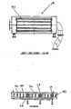
- the grate system (14) may be provided in additional and preferred embodiments as depicted in Figures 2 through 5 and Figures 9 through 14 .
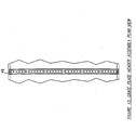
- Figure 2 provides a plan view of the grate assembly and ash roller (40).
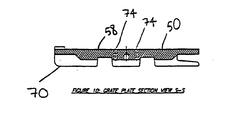
- the grate assembly may, in preferred embodiments, be comprised of multiple grate elements or plates (50), each grate plate perhaps in an abutting position relative to adjacent width edges (52) of width-adjacent grate plates and in an overlapping relationship relative to length-adjacent grate plates.
- width and “length” may define directions relative to the dimensions of the grate assembly (14).
- the grate plates overlap adjacent grate plates in the length direction of the assembly or in direction (54). Abutment of grate plates may occur along direction (56).
- Each grate plate may form a substantially planar surface (58) as depicted in Figure 5 and 13 , and therefore, grate system or assembly (14) may have a substantially unobstructed planar surface (60) when the grate plates are connected.
- the substantially planar features of the grate assembly and plates may improve the combustion and migration of mass fuel by minimizing obstruction to the mass fuel.
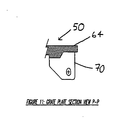
- grate elements or plates (50) interconnect such that an overlap (62) may exist between adjacent plates.
- the interconnect between plates may also be made via overlapping segments (64) such that, when overlapping segments are connected, an interlock system (66) is provided.
- Each grate plate may preferably be provided with integral tabs (68) to aid in interlocking or connecting adjacent plates as well as perhaps cooling.
- the interlock system may serve to maintain or hold the planar surface (60) of the grate assembly and thereby preventing substantial non-planar movement of the grate plates.
- the grate elements (50) may further comprise, according to a preferred embodiment, integral ribs or supports (70) that may serve to provide structural rigidity to the grate assembly and grate plates and may provide a means of cooling the grate assembly.
- Overlap spacers or spacer elements (72) may be provided integral to said grate plates to establish a space between the overlapping segments (64) of adjacent grate plates.
- a space may, therefore, be created between overlapping segments, therefore allowing a gas flow through the overlapping section of grate plates.
- the gas introduced between spaces of overlapping grate plates can be primarily combustion gas introduced from the combustion gas feeds or plenums (26), via inlets (28).
- Other gases may be introduced through the space or gap between grate plates, including but not limited to grate cooling gases preferably introduced as recycled combusted gas through inlet 30.
- Inlets (28) and (30) of each plenum may be controlled in an independent manner relative to other combustion gas feeds or plenums, a multiple of plenums being depicted in a preferred embodiment of Figure 1 .
- the control of combustion or recycled combusted gases may be automatically controlled via automatic control valves, poppets, dampers or other suitable means that may vary the flow or velocity over time.
- the introduction of combustion gas, mix gas, a secondary gas, two gases, or even recycled combusted gas may be made through the plenums such as plenums (26) in a pulsed fashion, via automatic control valves or poppets associated with individual inlets (28) and (30). Therefore, and given a plurality of combustion gas feed or plenums (26) placed along the grate assembly (14) as depicted in Figure 1 , zones or sections of the grate assembly may be independently controlled, for example and not by way of limitation, for combustion or for grate cooling.
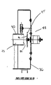
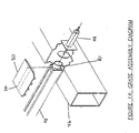
- each grate plate (50) may include inlets, nozzles, or apertures (74) for introducing a secondary, mix, or agitating gas to the top surface of the grate or to material thereupon. More particularly, and according to a preferred embodiment, a secondary, mix, or agitation gas may be introduced through secondary gas feeds or plenums such as plenums (76). Plenums (76) may be in fluid communication with combustion gas feeds or plenums (26) so as to provide the same type of gas. Alternatively, the secondary gas feeds may provide a distinct gas supply.
- secondary or agitation gas may be introduced from the secondary gas feeds or plenums (76) to secondary or agitation gas headers (78) via a plurality of introducing elements, or preferably, poppets (44).
- Gas headers (78) may be attached to an underside of grate plates (50) via bolts and bolt holes (79).
- an individual poppet may be actuated to close a header supply tube (80) or gas housing (93).
- Each poppet (44) may be controlled in an independent manner relative to other poppets, a multiple of poppets depicted in a preferred embodiment of Figure 1 .
- each poppet (44) may also include a gas housing (93) having an open end (94). Operating at the open end (94) of the gas housing (93) may be a controllable cap (95) to permit a gas pulse to occur by moving and opening the end of the gas housing (93). As shown, the operation of the controllable cap (95) may be made externally through some type of connection whether mechanical, electrical, or otherwise. To aid in sealing the poppet (44) it may include a seal (96) on either the controllable cap (95) or the gas housing (93) as can be easily appreciated. The seal (96) may also be made of an appropriate material, such as an elastomer or even VitonTM to withstand the potentially harsh environment at the location of the poppet (44).
- control of secondary, mix, or even agitation gases may be automatically controlled via the poppets, wherein the secondary or agitation gas flow or velocity from zones or sections of apertures (74) of particular grates (50) preferably may vary as needed for proper combustion.
- gas headers (78) insure a consistent and controlled flow of gas to sets of apertures (74).
- Figures 12 and 14 depict a preferred embodiment wherein one header may be in fluid communication with a single poppet (44).
- zones or sections of grates may be supplied with automatically controlled secondary or agitation gas. Therefore, and given a preferred plurality of poppets (44) placed along the grate assembly (14) as depicted in Figure 1 , zones or sections of the grate assembly may be independently controlled, for example and not by way of limitation, for combustion or for grate cooling.
- the pulsed introduction of a secondary gas may be independent of the combustion gas feeds or of any gas introduced from the combustion gas feeds or plenums (26).
- the introduction of combustion gas, including pulsed introduction may likewise be independent of the secondary or agitation gas plenums (76) and poppets (44). Therefore, multiple pulsing systems, and multiple control of the pulsing systems, for gas introduction may function within the combustion system of the present invention.
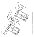
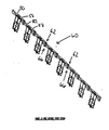
- the combustion system or furnace may comprise a vibration system (90) as generally depicted in Figure 1 .
- the vibration system (90) may also serve to provide agitation of ash and agglomerated combustion by-product or even slag present on the grate assembly (14) and to further aid in transportation of material along the grate assembly. Additionally, the vibration of mass fuel upon the grate assembly may further provide additional exposure of fuel, through agitation, to combustion.
- Vibration system (90) may be comprised of a single or multiple vibration elements (92), such as in the form of typical oscillation or vibration devices.
- the vibration elements may be directly connected to the grate assembly (14) or may be operationally connected to the grate assembly via vibration interconnect elements.
- the vibration element or elements (92) may be connected to zones or portions of grate elements or plates (50) via a vibration interconnect rod (94), as depicted in Figure 9 , running the width of either single or multiple grate plates (50) through ribs (70). Accordingly, multiple sections or zones may be vibrated such as to remove agglomerated combustion by-product and to transport ash and agglomerated combustion by-product along the grate assembly.
- Each zone or portion of the grate assembly (14) or each zone or portion or each grate plate (50) of a plurality of grate plates or elements may be independently vibrated via vibration elements (92).
- one vibration element (92) may vibrate either the entire grate assembly (14) or an individual zone or portion of grate assembly (14) or an individual zone or portion or individual grate element (50).
- the vibration system (90) can provide for the independent control of vibration for each vibration element (92) and also for each zone or portion of the grate assembly or grate plates, or of each individual grate plate. Therefore, individual elements, plates, zones or portions of the grate assembly or plurality of grate plates may be independently vibrationally responsive to vibratory movements of the vibration system.
- a combustion control system (100) may be provided to monitor and control various operational parameters of the combustion system. Temperature sensors may be provided to monitor temperature(s) in the combustion chamber. The control system (100) may be individually responsive to single or multiple temperature sensors and may adjust operational parameters of the system within particular zones or portions of the combustion chamber relative to the grate assembly. In one embodiment a first temperature sensor or sensors may monitor combustion temperatures while a second temperature sensor or sensors may monitor post-combustion temperatures within the combustion chambers (20) and (22).
- combustion control system (100) may coordinate combustion parameters of the combustion system to optimize throughput and combustion efficiency. Each of these parameters may be controlled as is easily understood by those of ordinary skill in the art. Coordination of combustion parameters may provide for the control of various combustion system sub-components, such as, but not limited to those set forth in the claims and: mass fuel feed elements (18) and (20); combustion gas feed via plenums (26) and inlets (28) and (32); secondary or agitation gas feed via feed (34), plenums (76) and poppets (34); and post-combustion or recycled combusted gas feeds via inlets (30) and (42), such as but not limited to serving as a cooling or ash and agglomerated combustion by-product reduction system; and any combinations or permutations of such described systems.
- Monitored combustion parameters within the combustion chambers may comprise, but are not limited to: oxygen content, combustion gas oxygen content, carbon monoxide content, combustion gas carbon monoxide content, temperature, combustion temperature, post-combustion temperature, the relation between a fuel feed rate and a combustion gas feed rate, fuel migration rate, fuel bed depthand any combinations or permutations of such parameters. Parameters may be automatically controlled through programming or other automation as would be readily understood.
- a low air fuel feed may be provided so that the amount of air introduced with the fuel is not the typical amount such as would be introduced when a typical often open air feed apparatus would be operated. This can be accomplished by providing doors or the like which limit open air exposure.
- a third gas feed situated at any location but likely most effective if positioned after combustion has occurred may be provided.
- This third gas feed can be used to independently control temperature. It may be configured to use recycled or even combusted gas and may feed such either above or below the grate system (14). This temperature control gas may serve as a cooling gas, of course.
Landscapes
- Engineering & Computer Science (AREA)
- Mechanical Engineering (AREA)
- General Engineering & Computer Science (AREA)
- Chemical & Material Sciences (AREA)
- Combustion & Propulsion (AREA)
- Incineration Of Waste (AREA)
- Fluidized-Bed Combustion And Resonant Combustion (AREA)
- Waste-Gas Treatment And Other Accessory Devices For Furnaces (AREA)
- Furnace Charging Or Discharging (AREA)
- Vertical, Hearth, Or Arc Furnaces (AREA)
- Feeding And Controlling Fuel (AREA)
- Glass Compositions (AREA)
- Pressure-Spray And Ultrasonic-Wave- Spray Burners (AREA)
- Combustion Of Fluid Fuel (AREA)
- Solid-Fuel Combustion (AREA)
- Regulation And Control Of Combustion (AREA)
Claims (19)
- Four de combustion de carburant de masse comprenant :a. un élément d'alimentation de carburant de masse (18, 20) ;b. une chambre de combustion (22) positionnée pour recevoir le carburant dudit élément d'alimentation de carburant de masse (18, 20) ;c. un système de grille (14) à l'intérieur de ladite chambre de combustion et ayant une extrémité d'entrée et une extrémité de sortie sur lesquelles le carburant de masse est transporté ;d. une alimentation de gaz de combustion (26) à l'intérieur de ladite chambre de combustion ;e. une alimentation de gaz de mélange (34) à l'intérieur de ladite chambre de combustion ;f. un système de pulsation de gaz de mélange indépendant (44) qui est indépendant de ladite alimentation de gaz de combustion et auquel ladite alimentation de gaz de mélange est sensible ; etg. un système de décharge de cendres (39) situé à proximité de ladite extrémité de sortie dudit système de grille,dans lequel ladite alimentation de gaz de combustion (26) alimente le gaz de combustion par ledit système de grille, caractérisé en ce que ladite alimentation de gaz de mélange (34) alimente le gaz de mélange par ledit système de grille.
- Four de combustion de carburant de masse selon la revendication 1, dans lequel ledit système de pulsation de gaz (44) comprend un élément à clapet auquel l'alimentation de gaz est sensible.
- Four de combustion de carburant de masse selon la revendication 1, dans lequel ledit système de pulsation de gaz comprend une pluralité d'éléments à clapet indépendamment contrôlables à laquelle l'alimentation de gaz est sensible.
- Four de combustion de carburant de masse selon la revendication 1, et comprenant en outre un système de contrôle de combustion (100) qui comprend un système de coordination de paramètre de combustion.
- Four de combustion de carburant de masse selon la revendication 1 et comprenant en outre une alimentation de gaz de contrôle de température (30) à l'intérieur de ladite chambre de combustion.
- Four de combustion de carburant de masse selon la revendication 5, dans lequel ladite alimentation de gaz de contrôle de température (30) à l'intérieur de ladite chambre de combustion comprend une alimentation de gaz sensiblement non combustible.
- Four de combustion de carburant de masse selon la revendication 6, dans lequel ladite alimentation de gaz sensiblement non combustible comprend une alimentation de gaz brûlée recyclée (42) à l'intérieur de ladite chambre de combustion.
- Four de combustion de carburant de masse selon la revendication 5, dans lequel ladite alimentation de gaz de contrôle de température (30) à l'intérieur de ladite chambre de combustion comprend une alimentation de gaz de contrôle de température (30) qui est indépendante de ladite alimentation de gaz de combustion (26) et de ladite alimentation de gaz de mélange (34).
- Four de combustion de carburant de masse selon la revendication 5, dans lequel ladite alimentation de gaz de contrôle de température (30) à l'intérieur de ladite chambre de combustion comprend une alimentation de gaz de refroidissement.
- Four de combustion de carburant de masse selon la revendication 9, dans lequel ladite alimentation de gaz de refroidissement comprend une alimentation de gaz recyclé.
- Four de combustion de carburant de masse selon la revendication 5, dans lequel ladite alimentation de gaz de contrôle de température à l'intérieur de ladite chambre de combustion comprend une alimentation de gaz postcombustion à l'intérieur de ladite chambre de gaz.
- Four de combustion de carburant de masse selon la revendication 5 ou 11, dans lequel ladite alimentation de gaz de contrôle de température à l'intérieur de ladite chambre de combustion comprend une alimentation de gaz supérieure positionnée au-dessus dudit système de grille (14).
- Four de combustion de carburant de masse selon la revendication 5 ou 11, dans lequel ladite alimentation de gaz de contrôle de température à l'intérieur de ladite chambre de combustion comprend une alimentation de gaz de contrôle de température positionnée au-dessous dudit système de grille.
- Four de combustion de carburant de masse selon la revendication 5, dans lequel ledit élément d'alimentation de carburant de masse comprend un système d'alimentation de carburant de masse de faible introduction d'air.
- Four de combustion de carburant de masse selon la revendication 5, dans lequel ladite alimentation de gaz de contrôle de température à l'intérieur de ladite chambre de combustion comprend un système de réduction de sous-produits de combustion agglomérés.
- Four de combustion de carburant de masse selon la revendication 15, dans lequel ledit système de réduction de sous-produits de combustion agglomérés comprend une alimentation de gaz de réduction de sous-produits de combustion agglomérés.
- Four de combustion de carburant de masse selon la revendication 1, dans lequel ledit système de grille (14) est incliné et comprend une pluralité de zones de grille vibrante qui sont chacune individuellement sensibles à un élément de vibration (92).
- Four de combustion de carburant de masse selon la revendication 1 et comprenant en outre un système de pulsion de gaz auquel ladite alimentation de gaz de combustion est sensible.
- Four de combustion de carburant de masse selon la revendication 18, dans lequel ledit système de pulsion de gaz comprend un système de pulsion de gaz variable.
Applications Claiming Priority (3)
| Application Number | Priority Date | Filing Date | Title |
|---|---|---|---|
| US13552799P | 1999-05-21 | 1999-05-21 | |
| US135527P | 1999-05-21 | ||
| PCT/US2000/013791 WO2000071937A1 (fr) | 1999-05-21 | 2000-05-20 | Systeme de combustion de carburant ameliore |
Publications (3)
| Publication Number | Publication Date |
|---|---|
| EP1188022A1 EP1188022A1 (fr) | 2002-03-20 |
| EP1188022A4 EP1188022A4 (fr) | 2005-02-02 |
| EP1188022B1 true EP1188022B1 (fr) | 2010-03-24 |
Family
ID=22468498
Family Applications (1)
| Application Number | Title | Priority Date | Filing Date |
|---|---|---|---|
| EP00936093A Expired - Lifetime EP1188022B1 (fr) | 1999-05-21 | 2000-05-20 | Systeme de combustion de carburant ameliore |
Country Status (14)
| Country | Link |
|---|---|
| US (1) | US6655304B1 (fr) |
| EP (1) | EP1188022B1 (fr) |
| JP (2) | JP3538384B2 (fr) |
| AT (1) | ATE462110T1 (fr) |
| AU (2) | AU776445B2 (fr) |
| BR (1) | BR0010781B1 (fr) |
| CA (2) | CA2374593C (fr) |
| CR (1) | CR6537A (fr) |
| DE (1) | DE60044059D1 (fr) |
| DK (1) | DK1188022T3 (fr) |
| EA (1) | EA006188B1 (fr) |
| MX (1) | MXPA01011856A (fr) |
| PT (1) | PT1188022E (fr) |
| WO (1) | WO2000071937A1 (fr) |
Cited By (1)
| Publication number | Priority date | Publication date | Assignee | Title |
|---|---|---|---|---|
| CN103411206A (zh) * | 2013-08-12 | 2013-11-27 | 上海应用技术学院 | 带有双层错位二次风喷管和石灰石粉喷管系统的链条锅炉 |
Families Citing this family (26)
| Publication number | Priority date | Publication date | Assignee | Title |
|---|---|---|---|---|
| PT1188022E (pt) | 1999-05-21 | 2010-06-21 | Barlow Projects Inc | Sistema melhorado para queima de combustíveis em massa |
| AT412500B (de) * | 2002-10-29 | 2005-03-25 | Wilde Andreas Ing | Verfahren zum verbrennen von kleinstückeligem brennstoff |
| FR2857732A1 (fr) * | 2003-07-15 | 2005-01-21 | Perge | Chaudiere de chauffage a combustible du type a elements individualises |
| DE10347340A1 (de) * | 2003-10-11 | 2005-05-19 | Forschungszentrum Karlsruhe Gmbh | Vorrichtung und Verfahren zur Optimierung des Abgasausbrandes in Verbrennungsanlagen |
| EP1745390A4 (fr) * | 2004-02-06 | 2009-09-23 | Ubmatrix Inc | Mecanisme et procede de forme de liaison de donnees et de metadonnees |
| US7146916B2 (en) * | 2004-05-14 | 2006-12-12 | Eco/Technologies, Llc | Starved air inclined hearth combustor |
| JP2008509000A (ja) | 2004-08-13 | 2008-03-27 | フォース テクノロジー | 固体物体と気体とに関わる過程を強める方法および装置 |
| EP1785669A1 (fr) * | 2005-11-09 | 2007-05-16 | Lentjes GmbH | Procédé pour réguler l'apport de matière combustible dans un four de combustion |
| WO2007128318A1 (fr) * | 2006-05-10 | 2007-11-15 | Force Technology | Procédé, dispositif et système permettant d'améliorer la combustion d'objets solides |
| DE102006026434B3 (de) * | 2006-06-07 | 2007-12-13 | Forschungszentrum Karlsruhe Gmbh | Verfahren zur Verbesserung der Schlackequalität von Rostfeuerungsanlagen |
| US7921786B2 (en) * | 2007-05-10 | 2011-04-12 | Riley Power Inc. | Grating system and sidewall seal arrangement for oscillating grate stoker |
| PL383941A1 (pl) * | 2007-12-03 | 2009-06-08 | Witold Kowalewski | Kocioł rusztowy, sposób modernizacji kotła rusztowego oraz sposób likwidowania szkodliwych przedmuchów powietrza, nie biorącego udziału w procesie spalania w kotle rusztowym |
| US20090293785A1 (en) * | 2008-06-03 | 2009-12-03 | Gallant James | Combustion system with cellular chain grate |
| WO2010124037A1 (fr) * | 2009-04-23 | 2010-10-28 | Eckman Environmental Corporation | Appareil et procédés de recyclage de l'eau grise |
| US9353944B1 (en) * | 2009-09-03 | 2016-05-31 | Poet Research, Inc. | Combustion of high solids liquid |
| IT1396019B1 (it) * | 2009-10-16 | 2012-11-09 | Girolamo Camoni | Macchina per lo smaltimento della pollina. |
| CN102588982B (zh) * | 2011-01-11 | 2014-06-25 | 陈喜春 | 锅炉混合气冷助燃活动管式炉排 |
| US8826835B1 (en) * | 2011-01-18 | 2014-09-09 | General Kinematics Corporation | Controlling carbon content in conveyed heated material |
| US11135728B2 (en) | 2012-02-16 | 2021-10-05 | Biochar Now, Llc | Lid assembly for portable biochar kiln |
| WO2013179313A1 (fr) * | 2012-05-31 | 2013-12-05 | Wte Waste To Energy Canada, Inc | Procédé de gazéification discontinue séquentielle avancée |
| EP2870412A1 (fr) * | 2012-07-06 | 2015-05-13 | Babcock & Wilcox Vølund A/S | Foyer mécanique à grille vibrante |
| CN104864418A (zh) * | 2014-02-20 | 2015-08-26 | 天津特斯达生物质能源机械有限公司 | 除焦助燃式生物质秸秆颗粒燃烧炉、灶 |
| CN103939887A (zh) * | 2014-04-15 | 2014-07-23 | 天津市双鑫锅炉辅机有限公司 | 一种防结焦生物质燃烧机 |
| US10385273B2 (en) * | 2016-04-03 | 2019-08-20 | Biochar Now, Llc | Biochar kiln |
| EP3682168A4 (fr) * | 2017-09-11 | 2021-05-26 | Enero Inventions Inc. | Calcul de libération de chaleur dynamique pour une commande de rétroaction améliorée de processus de combustion à base de combustible solide |
| CN112963824B (zh) * | 2021-04-08 | 2022-08-12 | 苏州乐米凡电气科技有限公司 | 一种具有自动排灰功能的新能源锅炉 |
Family Cites Families (125)
| Publication number | Priority date | Publication date | Assignee | Title |
|---|---|---|---|---|
| US654774A (en) | 1899-08-19 | 1900-07-31 | Wilfred Rothery Wood | Combustion-furnace. |
| US1664082A (en) | 1922-02-06 | 1928-03-27 | Riley Stoker Corp | Underfeed furnace |
| US2072450A (en) | 1932-05-13 | 1937-03-02 | Philadelphia & Reading Coal & | Furnace |
| GB402934A (en) * | 1932-12-01 | 1933-12-14 | Kai Petersen | New or improved method of and apparatus for admitting secondary combustion air into the combustion chambers of furnaces |
| DE611919C (de) * | 1934-05-26 | 1935-04-09 | Adolf Lanz | Verfahren zur Herstellung von Geweben von der mehrfachen Breite des Webstuhles |
| GB795252A (en) * | 1955-07-07 | 1958-05-21 | Babcock & Wilcox Ltd | Improvements relating to furnace chambers with secondary air supplies |
| CH405577A (de) | 1963-11-27 | 1966-01-15 | Von Roll Ag | Verfahren zur Verbrennung von sperrigen Brennstoffen unterschiedlicher Beschaffenheit mittels einer mechanischen Rostfeuerung sowie Rostfeuerung zur Durchführung dieses Verfahrens |
| CH493791A (de) | 1968-01-30 | 1970-07-15 | Volkswagenwerk Ag | Müllverbrennungsanlage |
| US3577938A (en) | 1968-05-10 | 1971-05-11 | Rose Downs & Thompson Ltd | Incinerators |
| CH476949A (de) | 1968-07-08 | 1969-08-15 | Von Roll Ag | Verfahren zur gemeinsamen Verbrennung von festen Abfallstoffen, insbesondere Stadtmüll, und wässrigem Klärschlamm, insbesondere aus kommunalen Kläranlagen, sowie Einrichtung zur Ausführung des Verfahrens |
| FR1601266A (fr) * | 1968-12-30 | 1970-08-10 | Stein & Roubaix | Dispositif incinerateur |
| US3559598A (en) | 1969-03-21 | 1971-02-02 | Elson R Mcclure | Refuse burner |
| US3557723A (en) | 1969-06-06 | 1971-01-26 | Riley Stoker Corp | Furnace for burning wet fuels and method of operating same |
| US3556025A (en) | 1969-08-04 | 1971-01-19 | Ferro Tech Ind Inc | Incinerator for refuse |
| US3566810A (en) | 1969-08-12 | 1971-03-02 | Conton Stoker Corp | Incinerator stoker winged grate |
| US3645217A (en) | 1970-02-24 | 1972-02-29 | P R Akroud Ltd | Incinerators |
| US3651770A (en) | 1970-04-23 | 1972-03-28 | Von Roll Ag | Mechanical grate for incinerators |
| US3669039A (en) | 1970-08-27 | 1972-06-13 | Simpson Timber Co | Refuse burner for wood waste,bark residues,and other combustible solids |
| US3870652A (en) | 1971-04-02 | 1975-03-11 | Charles M Whitten | Production of activated char using a moving grate stoker furnace |
| US3745941A (en) | 1971-12-03 | 1973-07-17 | B Reilly | Slagging refuse incinerators |
| US3771470A (en) | 1972-07-31 | 1973-11-13 | R Hampton | Incinerator stoker siftings conveyor mechanism |
| US3812794A (en) | 1972-09-21 | 1974-05-28 | F Taylor | Stairstep jet pulse incinerator |
| US3797415A (en) | 1972-10-30 | 1974-03-19 | J Young | Incinerator with a plurality of outer walls and a hollow grate |
| FR2208094B3 (fr) | 1972-11-24 | 1976-07-23 | Bazin Claudine | |
| US3823677A (en) | 1972-12-15 | 1974-07-16 | Combustion Eng | Gravity flow incinerator |
| FR2215587B1 (fr) | 1973-01-29 | 1977-06-10 | Hitachi Shipbuilding Eng Co | |
| FR2235335B1 (fr) | 1973-06-27 | 1978-01-27 | Martin Feuerungsbau | |
| CH567230A5 (fr) | 1973-10-08 | 1975-09-30 | Kuenstler Hans | |
| US3955512A (en) | 1973-11-30 | 1976-05-11 | Josef Martin Feuerungsbau Gmbh | Refuse incinerator |
| US3926130A (en) | 1974-08-20 | 1975-12-16 | Prvni Brnenska Strojirna | Incineration of hospital refuse |
| CH585875A5 (fr) | 1975-01-21 | 1977-03-15 | Lohner Jacques | |
| CH585370A5 (fr) * | 1975-04-29 | 1977-02-28 | Von Roll Ag | |
| US4060041A (en) | 1975-06-30 | 1977-11-29 | Energy Products Of Idaho | Low pollution incineration of solid waste |
| US4103627A (en) | 1975-09-04 | 1978-08-01 | Morse Boulger, Inc. | Stoker and grate therefore |
| US3995568A (en) | 1975-11-12 | 1976-12-07 | Miro Dvirka | Incinerator and combustion air system therefor |
| US4038930A (en) | 1976-03-17 | 1977-08-02 | Barkhuus Per W | Furnace for incinerating refuse |
| US4200047A (en) | 1977-04-01 | 1980-04-29 | Claudius Peters Ag | Two part grate for stokers with reciprocating grate plates |
| LU77677A1 (fr) | 1977-07-01 | 1977-10-07 | ||
| CH622084A5 (fr) | 1977-07-14 | 1981-03-13 | Schenck Ag Carl | |
| US4193354A (en) | 1977-10-20 | 1980-03-18 | Woods Maurice G | Solid waste disposal system |
| USD254749S (en) | 1977-12-21 | 1980-04-15 | Sjunne Johansson | Stoker apparatus for heating boilers |
| USD256723S (en) | 1977-12-30 | 1980-09-02 | The United Corporation | Waste incineration installation |
| DE2935494A1 (de) | 1979-09-03 | 1981-03-19 | Saxlund, geb. Eriksen, Astrid Alice, 3040 Soltau | Verfahren und vorrichtung zum betreiben einer kesselanlage mit stokerfeuerung |
| US4335660A (en) | 1980-06-02 | 1982-06-22 | Research Cottrell Technologies, Inc. | Apparatus and method for flue gas recirculation in a solid fuel boiler |
| US4389978A (en) * | 1980-06-10 | 1983-06-28 | Parkinson Cowan Gwb Limited | Grates |
| US4491077A (en) | 1980-08-20 | 1985-01-01 | Richardsons Westgarth & Co., Ltd. | Vibrating hearth burners |
| US4385567A (en) * | 1980-10-24 | 1983-05-31 | Solid Fuels, Inc. | Solid fuel conversion system |
| US4438705A (en) | 1981-03-27 | 1984-03-27 | Basic J N Sen | Incinerator with two reburn stages, and, optionally, heat recovery |
| US4475469A (en) | 1981-03-27 | 1984-10-09 | Basic J N Sen | Pulsating incinerator hearth |
| US4432287A (en) | 1981-05-04 | 1984-02-21 | Morse Boulger, Inc. | Incinerator and hearth construction therefor |
| JPS5837415A (ja) * | 1981-08-28 | 1983-03-04 | 株式会社 タクマ | 低NOx用ごみ焼却炉 |
| US4454860A (en) | 1981-10-07 | 1984-06-19 | Stephen A. Schafer | Fuel stoker and furnace |
| US4430948A (en) | 1981-10-07 | 1984-02-14 | Western Heating, Inc. | Fuel stoker and furnace |
| DE3148446C2 (de) | 1981-12-08 | 1984-02-09 | L. & C. Steinmüller GmbH, 5270 Gummersbach | Roststabloser gekühlter Schüttelrost |
| US4366759A (en) | 1982-02-16 | 1983-01-04 | Samuel Foresto | Mass burning self-cleaning incinerator |
| US4434725A (en) | 1982-02-16 | 1984-03-06 | Samuel Foresto | Mass burning self-cleaning incinerator |
| GB2120764B (en) | 1982-05-13 | 1985-08-14 | Voelund Miljoeteknik | A stepped grate for an incinerator plant |
| CH669447A5 (fr) | 1982-05-13 | 1989-03-15 | Von Roll Ag | |
| US5302115A (en) * | 1982-09-15 | 1994-04-12 | Damper Design, Inc. | Burner register assembly |
| JPS59180213A (ja) | 1983-03-30 | 1984-10-13 | Takuma Co Ltd | 階段式スト−カ |
| JPS59180215A (ja) | 1983-03-30 | 1984-10-13 | Takuma Co Ltd | 都市ごみ焼却炉のクリンカ−防止装置 |
| JPS59183212A (ja) * | 1983-04-04 | 1984-10-18 | Takuma Co Ltd | 階段式スト−カの侵入異物排出装置 |
| SE436298B (sv) * | 1983-04-26 | 1984-11-26 | Kils El Ab | Anordning vid en vermepanna anordning vid en vermepanna |
| US4475468A (en) | 1983-05-16 | 1984-10-09 | Ishikawajima-Harima Jukogyo Kabushiki Kaisha | Incinerator with moving-bed stoker |
| US4528917A (en) | 1983-07-05 | 1985-07-16 | Northwest Iron Fireman, Inc. | Solid fuel burner |
| JPS60147015A (ja) * | 1984-01-09 | 1985-08-02 | Takuma Co Ltd | 並列揺動式階段スト−カ |
| US4576101A (en) | 1984-02-27 | 1986-03-18 | Detroit Stoker Company | Stoker |
| US4516511A (en) | 1984-04-06 | 1985-05-14 | Kuo Tsung H | Refuse incineration system |
| US4954034A (en) | 1984-10-05 | 1990-09-04 | Zurn Industries, Inc. | Vibratory fuel feeder for furnaces |
| DE3521266A1 (de) | 1985-06-13 | 1986-12-18 | Walter Josef Dipl.-Ing. 8000 München Martin | Roststab fuer einen feuerungsrost einer grossfeuerung und feuerungsrost fuer diese grossfeuerung |
| EP0236298B1 (fr) * | 1985-09-09 | 1990-01-17 | Günther Förster | Procede et dispositif de combustion de matieres solides et/ou liquides |
| IT1235900B (it) | 1985-10-11 | 1992-12-02 | Vaifro Vittorio Bonomelli | Griglia di combustione a gradini mobili per combustibili solidi in particolare rifiuti solidi urbani e assimilabili |
| DE3538059A1 (de) | 1985-10-25 | 1987-04-30 | Krupp Polysius Ag | Vorrichtung zum kuehlen von heissem gut |
| JPS62169914A (ja) | 1986-01-21 | 1987-07-27 | Ishikawajima Harima Heavy Ind Co Ltd | 流動床炉の安定燃焼法 |
| US4992043A (en) * | 1986-04-16 | 1991-02-12 | Nea Technologies, Inc. | Pulse combustion energy system |
| US4975045A (en) * | 1986-04-23 | 1990-12-04 | Eagleair, Inc. | Burner register with dual inlet air valves |
| US4694757A (en) | 1986-04-30 | 1987-09-22 | The City Of Columbus, Ohio | Tuyere construction for refuse burning boiler systems |
| DE3616630A1 (de) | 1986-05-16 | 1987-11-19 | Krupp Polysius Ag | Kuehlvorrichtung |
| GB8615634D0 (en) | 1986-06-26 | 1986-07-30 | Incinerator Co Ltd | Combustion apparatus |
| US4771709A (en) | 1986-12-31 | 1988-09-20 | Applegate William G | Incineration air supply apparatus |
| US4709662A (en) | 1987-01-20 | 1987-12-01 | Riley Stoker Corporation | Fluidized bed heat generator and method of operation |
| DE8702507U1 (fr) * | 1987-02-18 | 1988-06-23 | Pauli, Balduin, Dr., 8035 Gauting, De | |
| JPS63294414A (ja) * | 1987-05-25 | 1988-12-01 | Takuma Co Ltd | 階段式焼却炉 |
| US4745884A (en) | 1987-05-28 | 1988-05-24 | Riley Stoker Corporation | Fluidized bed steam generating system |
| US4895084A (en) | 1987-12-18 | 1990-01-23 | Morse Boulger, Inc. | Stoker for refuse incinerators |
| EP0328359B1 (fr) | 1988-02-09 | 1993-12-22 | Ube Industries, Ltd. | Procédé d'incinération de déchets humides |
| US4838183A (en) * | 1988-02-11 | 1989-06-13 | Morse Boulger, Inc. | Apparatus and method for incinerating heterogeneous materials |
| JP2548313B2 (ja) * | 1988-07-19 | 1996-10-30 | 松下電子工業株式会社 | 半導体装置の製造方法 |
| US4955296A (en) * | 1988-12-01 | 1990-09-11 | Barlow James L | Incinerator grate assembly |
| US5044288A (en) | 1988-12-01 | 1991-09-03 | Barlow James L | Method and apparatus for the efficient combustion of a mass fuel |
| US5087269A (en) | 1989-04-03 | 1992-02-11 | Western Research Institute | Inclined fluidized bed system for drying fine coal |
| US4936231A (en) | 1989-08-11 | 1990-06-26 | Loyd Johnson | Solid waste garbage incinerator system |
| JPH07111247B2 (ja) | 1989-11-10 | 1995-11-29 | 石川島播磨重工業株式会社 | 廃棄物処理方法 |
| US4949653A (en) | 1989-12-06 | 1990-08-21 | Rast James P | Process and apparatus for incineration |
| US5307746A (en) * | 1990-02-28 | 1994-05-03 | Institute Of Gas Technology | Process and apparatus for emissions reduction from waste incineration |
| US5086714A (en) | 1990-04-16 | 1992-02-11 | Hladun Kenneth W | Vibratory hearth |
| FR2668815B1 (fr) | 1990-11-02 | 1993-04-09 | Chauffe Cie Gle | Procede d'incineration de dechets urbains dans une unite comportant un foyer a lit fluidise et une chaudiere, avec epuration intrinseque des fumees. |
| JPH04186008A (ja) | 1990-11-16 | 1992-07-02 | Nkk Corp | ごみ焼却炉燃焼装置 |
| ES2055466T5 (es) * | 1991-02-07 | 1997-02-01 | Martin Umwelt & Energietech | Procedimiento para la alimentacion de aire de combustion e instalacion de hogar. |
| JP2673627B2 (ja) | 1991-02-22 | 1997-11-05 | フォン ロール ウムヴェルトテクニック アクチエンゲゼルシャフト | ごみ焼却プラントの操作方法およびその制御システム |
| JPH0545423U (ja) | 1991-10-28 | 1993-06-18 | 株式会社ナカオ | 焼却炉 |
| TW235335B (fr) * | 1991-11-05 | 1994-12-01 | Mitsubishi Heavy Ind Ltd | |
| US5239935A (en) * | 1991-11-19 | 1993-08-31 | Detroit Stoker Company | Oscillating damper and air-swept distributor |
| JPH0756371B2 (ja) | 1992-02-21 | 1995-06-14 | 熱技研工業株式会社 | 焼却炉 |
| DE4233216A1 (de) * | 1992-07-09 | 1994-01-13 | Erfurt Feuerungsanlagen Gmbh | Feuerungssystem zum Verbrennen feuchter Schlämme |
| US5722333A (en) | 1992-09-30 | 1998-03-03 | Hyun; Kwangsoo | Incinerator furnace with fire grate and air supply |
| US5279234A (en) * | 1992-10-05 | 1994-01-18 | Chiptec Wood Energy Systems | Controlled clean-emission biomass gasification heating system/method |
| US5309850A (en) * | 1992-11-18 | 1994-05-10 | The Babcock & Wilcox Company | Incineration of hazardous wastes using closed cycle combustion ash vitrification |
| GB2276707B (en) | 1993-03-30 | 1997-02-26 | Wu I Cheng | Incinerator |
| US5762008A (en) * | 1993-04-20 | 1998-06-09 | Martin Gmbh Fuer Umwelt- Und Enetgietechnik | Burning fuels, particularly for incinerating garbage |
| TW239183B (fr) | 1993-06-01 | 1995-01-21 | Hitachi Shipbuilding Eng Co | |
| JP2788394B2 (ja) * | 1993-06-18 | 1998-08-20 | 株式会社クボタ | ゴミ焼却炉 |
| DE59405777D1 (de) | 1993-10-21 | 1998-05-28 | Asea Brown Boveri | Rost für eine Feuerungsanlage |
| DE4344906C2 (de) * | 1993-12-29 | 1997-04-24 | Martin Umwelt & Energietech | Verfahren zum Regeln einzelner oder sämtlicher die Verbrennung auf einem Feuerungsrost beeinflussender Faktoren |
| FR2718223B1 (fr) * | 1994-03-29 | 1996-06-21 | Babcock Entreprise | Dispositif d'enfournement de combustibles solides de grande taille dans un foyer, par exemple des pneus usagés entiers. |
| US5553554A (en) * | 1994-10-04 | 1996-09-10 | Urich, Jr.; Albert E. | Waste disposal and energy recovery system and method |
| DE19504588B4 (de) * | 1995-02-11 | 2006-07-13 | Khd Humboldt Wedag Gmbh | Rostplatte für Schubrostkühler zum Abkühlen von heißem Gut |
| JPH08278009A (ja) * | 1995-04-05 | 1996-10-22 | Takashige Sangyo Kk | ストーカ式焼却炉 |
| US5671687A (en) | 1995-06-16 | 1997-09-30 | Chen; Chwan Yuh | Incinerator having a fully automatic feeder |
| JPH0933017A (ja) * | 1995-07-18 | 1997-02-07 | Kubota Corp | ゴミ焼却炉 |
| JPH09159125A (ja) * | 1995-12-11 | 1997-06-20 | Kubota Corp | ゴミ焼却炉のストーカ装置 |
| US5906806A (en) * | 1996-10-16 | 1999-05-25 | Clark; Steve L. | Reduced emission combustion process with resource conservation and recovery options "ZEROS" zero-emission energy recycling oxidation system |
| JP3491126B2 (ja) * | 1997-06-16 | 2004-01-26 | Jfeエンジニアリング株式会社 | ごみ焼却炉の火格子燃焼空気流量推定方法及びその推定装置 |
| JP3580672B2 (ja) * | 1997-07-04 | 2004-10-27 | 株式会社タクマ | ストーカ式ごみ焼却炉 |
| PT1188022E (pt) | 1999-05-21 | 2010-06-21 | Barlow Projects Inc | Sistema melhorado para queima de combustíveis em massa |
-
2000
- 2000-05-20 PT PT00936093T patent/PT1188022E/pt unknown
- 2000-05-20 AU AU51456/00A patent/AU776445B2/en not_active Ceased
- 2000-05-20 CA CA002374593A patent/CA2374593C/fr not_active Expired - Fee Related
- 2000-05-20 EP EP00936093A patent/EP1188022B1/fr not_active Expired - Lifetime
- 2000-05-20 DK DK00936093.4T patent/DK1188022T3/da active
- 2000-05-20 AT AT00936093T patent/ATE462110T1/de active
- 2000-05-20 JP JP2000620286A patent/JP3538384B2/ja not_active Expired - Fee Related
- 2000-05-20 EA EA200101218A patent/EA006188B1/ru not_active IP Right Cessation
- 2000-05-20 WO PCT/US2000/013791 patent/WO2000071937A1/fr active IP Right Grant
- 2000-05-20 US US09/979,694 patent/US6655304B1/en not_active Expired - Lifetime
- 2000-05-20 DE DE60044059T patent/DE60044059D1/de not_active Expired - Lifetime
- 2000-05-20 MX MXPA01011856A patent/MXPA01011856A/es not_active Application Discontinuation
- 2000-05-20 AU AU2004237886A patent/AU2004237886B2/en not_active Ceased
- 2000-05-20 CA CA2653515A patent/CA2653515C/fr not_active Expired - Fee Related
- 2000-05-20 BR BRPI0010781-6A patent/BR0010781B1/pt not_active IP Right Cessation
-
2001
- 2001-12-20 CR CR6537A patent/CR6537A/es unknown
-
2003
- 2003-07-10 JP JP2003273116A patent/JP4902097B2/ja not_active Expired - Fee Related
Cited By (2)
| Publication number | Priority date | Publication date | Assignee | Title |
|---|---|---|---|---|
| CN103411206A (zh) * | 2013-08-12 | 2013-11-27 | 上海应用技术学院 | 带有双层错位二次风喷管和石灰石粉喷管系统的链条锅炉 |
| CN103411206B (zh) * | 2013-08-12 | 2015-07-22 | 上海应用技术学院 | 带有双层错位二次风喷管和石灰石粉喷管系统的链条锅炉 |
Also Published As
| Publication number | Publication date |
|---|---|
| WO2000071937A1 (fr) | 2000-11-30 |
| CA2374593C (fr) | 2009-02-17 |
| BR0010781B1 (pt) | 2010-11-03 |
| CA2374593A1 (fr) | 2000-11-30 |
| BR0010781A (pt) | 2002-07-02 |
| EP1188022A4 (fr) | 2005-02-02 |
| EA006188B1 (ru) | 2005-10-27 |
| ATE462110T1 (de) | 2010-04-15 |
| EA200101218A1 (ru) | 2002-04-25 |
| AU2004237886B2 (en) | 2007-10-25 |
| DE60044059D1 (de) | 2010-05-06 |
| JP2003500623A (ja) | 2003-01-07 |
| JP4902097B2 (ja) | 2012-03-21 |
| CR6537A (es) | 2003-05-22 |
| DK1188022T3 (da) | 2010-07-12 |
| US6655304B1 (en) | 2003-12-02 |
| AU2004237886A1 (en) | 2005-01-13 |
| EP1188022A1 (fr) | 2002-03-20 |
| AU776445B2 (en) | 2004-09-09 |
| MXPA01011856A (es) | 2003-09-04 |
| PT1188022E (pt) | 2010-06-21 |
| JP2004093113A (ja) | 2004-03-25 |
| JP3538384B2 (ja) | 2004-06-14 |
| CA2653515A1 (fr) | 2000-11-30 |
| AU5145600A (en) | 2000-12-12 |
| CA2653515C (fr) | 2010-11-23 |
Similar Documents
| Publication | Publication Date | Title |
|---|---|---|
| EP1188022B1 (fr) | Systeme de combustion de carburant ameliore | |
| US4385567A (en) | Solid fuel conversion system | |
| US4879958A (en) | Fluidized bed reactor with two zone combustion | |
| US5044288A (en) | Method and apparatus for the efficient combustion of a mass fuel | |
| SE447672B (sv) | Sett och apparat for forbrenning med fluidbedd | |
| EP0676023B1 (fr) | Four a grille | |
| SU1286114A3 (ru) | Устройство дл сжигани твердых видов топлива | |
| US20120247375A1 (en) | Grate clearing and ash removal system for gasification furnace | |
| US4771711A (en) | Furnace | |
| US4955296A (en) | Incinerator grate assembly | |
| EP0334846B1 (fr) | Regulation de l'air alimentant un incinerateur | |
| US5039301A (en) | Fluidized bed furnace | |
| US4986196A (en) | Solid waste incinerator system | |
| JPS61205720A (ja) | 横型流動床焼却炉 | |
| KR20000076315A (ko) | 산업 및 가정용 쓰레기 및 슬러지의 소각 플랜트 및 방법 | |
| JP3372526B2 (ja) | 廃棄物の処理方法及びその装置 | |
| KR101892907B1 (ko) | 분리형 소각로 자동 처리 설비 | |
| JP2009024900A (ja) | ボイラ装置 | |
| JPH06241426A (ja) | 廃棄物焼却炉 | |
| JPH02290402A (ja) | 流動床ボイラの熱回収制御方法 | |
| JP3004201B2 (ja) | ロータリーキルン | |
| JP2000230709A (ja) | 回転式汚泥切出装置を有する汚泥混焼炉 | |
| CA1184075A (fr) | Grille de foyer | |
| CA1210995A (fr) | Incinerateur de dechets | |
| JP2005351554A (ja) | 乾燥装置 |
Legal Events
| Date | Code | Title | Description |
|---|---|---|---|
| PUAI | Public reference made under article 153(3) epc to a published international application that has entered the european phase |
Free format text: ORIGINAL CODE: 0009012 |
|
| 17P | Request for examination filed |
Effective date: 20011217 |
|
| AK | Designated contracting states |
Kind code of ref document: A1 Designated state(s): AT BE CH CY DE DK ES FI FR GB GR IE IT LI LU MC NL PT SE |
|
| AX | Request for extension of the european patent |
Free format text: AL;LT;LV;MK;RO;SI |
|
| RAP1 | Party data changed (applicant data changed or rights of an application transferred) |
Owner name: BARLOW PROJECTS, INC. |
|
| RIN1 | Information on inventor provided before grant (corrected) |
Inventor name: BARLOW, JAMES L. |
|
| A4 | Supplementary search report drawn up and despatched |
Effective date: 20041216 |
|
| RIC1 | Information provided on ipc code assigned before grant |
Ipc: 7F 23L 9/00 B Ipc: 7F 23L 7/00 B Ipc: 7F 23J 11/00 B Ipc: 7F 23H 17/00 B Ipc: 7F 23C 9/00 B Ipc: 7F 23N 5/18 A Ipc: 7F 23L 1/02 B Ipc: 7F 23G 5/00 B Ipc: 7F 23G 5/44 B Ipc: 7F 23K 3/00 B Ipc: 7F 23J 1/00 B Ipc: 7F 23K 3/08 B Ipc: 7F 23N 5/02 B Ipc: 7F 23H 1/02 B Ipc: 7F 23G 5/50 B Ipc: 7F 23B 5/02 B Ipc: 7F 23C 9/08 B |
|
| 17Q | First examination report despatched |
Effective date: 20060912 |
|
| GRAP | Despatch of communication of intention to grant a patent |
Free format text: ORIGINAL CODE: EPIDOSNIGR1 |
|
| RIC1 | Information provided on ipc code assigned before grant |
Ipc: F23G 5/50 20060101ALI20090921BHEP Ipc: F23K 3/00 20060101ALI20090921BHEP Ipc: F23J 11/00 20060101ALI20090921BHEP Ipc: F23J 1/00 20060101ALI20090921BHEP Ipc: F23H 17/00 20060101ALI20090921BHEP Ipc: F23K 3/08 20060101ALI20090921BHEP Ipc: F23C 9/00 20060101ALI20090921BHEP Ipc: F23B 30/02 20060101ALI20090921BHEP Ipc: F23N 5/18 20060101AFI20090921BHEP Ipc: F23L 9/00 20060101ALI20090921BHEP Ipc: F23N 5/02 20060101ALI20090921BHEP Ipc: F23H 1/02 20060101ALI20090921BHEP Ipc: F23G 5/00 20060101ALI20090921BHEP Ipc: F23C 9/08 20060101ALI20090921BHEP Ipc: F23G 5/44 20060101ALI20090921BHEP Ipc: F23L 7/00 20060101ALI20090921BHEP Ipc: F23L 1/02 20060101ALI20090921BHEP |
|
| GRAS | Grant fee paid |
Free format text: ORIGINAL CODE: EPIDOSNIGR3 |
|
| GRAA | (expected) grant |
Free format text: ORIGINAL CODE: 0009210 |
|
| AK | Designated contracting states |
Kind code of ref document: B1 Designated state(s): AT BE CH CY DE DK ES FI FR GB GR IE IT LI LU MC NL PT SE |
|
| REG | Reference to a national code |
Ref country code: GB Ref legal event code: FG4D |
|
| REG | Reference to a national code |
Ref country code: CH Ref legal event code: EP |
|
| REG | Reference to a national code |
Ref country code: IE Ref legal event code: FG4D |
|
| REF | Corresponds to: |
Ref document number: 60044059 Country of ref document: DE Date of ref document: 20100506 Kind code of ref document: P |
|
| REG | Reference to a national code |
Ref country code: SE Ref legal event code: TRGR |
|
| REG | Reference to a national code |
Ref country code: NL Ref legal event code: T3 |
|
| REG | Reference to a national code |
Ref country code: PT Ref legal event code: SC4A Free format text: AVAILABILITY OF NATIONAL TRANSLATION Effective date: 20100614 |
|
| REG | Reference to a national code |
Ref country code: DK Ref legal event code: T3 |
|
| PG25 | Lapsed in a contracting state [announced via postgrant information from national office to epo] |
Ref country code: ES Free format text: LAPSE BECAUSE OF FAILURE TO SUBMIT A TRANSLATION OF THE DESCRIPTION OR TO PAY THE FEE WITHIN THE PRESCRIBED TIME-LIMIT Effective date: 20100705 Ref country code: GR Free format text: LAPSE BECAUSE OF FAILURE TO SUBMIT A TRANSLATION OF THE DESCRIPTION OR TO PAY THE FEE WITHIN THE PRESCRIBED TIME-LIMIT Effective date: 20100625 |
|
| PG25 | Lapsed in a contracting state [announced via postgrant information from national office to epo] |
Ref country code: MC Free format text: LAPSE BECAUSE OF NON-PAYMENT OF DUE FEES Effective date: 20100531 |
|
| PLBE | No opposition filed within time limit |
Free format text: ORIGINAL CODE: 0009261 |
|
| STAA | Information on the status of an ep patent application or granted ep patent |
Free format text: STATUS: NO OPPOSITION FILED WITHIN TIME LIMIT |
|
| PG25 | Lapsed in a contracting state [announced via postgrant information from national office to epo] |
Ref country code: CY Free format text: LAPSE BECAUSE OF NON-PAYMENT OF DUE FEES Effective date: 20100520 |
|
| 26N | No opposition filed |
Effective date: 20101228 |
|
| PG25 | Lapsed in a contracting state [announced via postgrant information from national office to epo] |
Ref country code: IT Free format text: LAPSE BECAUSE OF NON-PAYMENT OF DUE FEES Effective date: 20100520 |
|
| PGFP | Annual fee paid to national office [announced via postgrant information from national office to epo] |
Ref country code: IT Payment date: 20100624 Year of fee payment: 11 Ref country code: ES Payment date: 20110524 Year of fee payment: 12 |
|
| PGRI | Patent reinstated in contracting state [announced from national office to epo] |
Ref country code: IT Effective date: 20110616 |
|
| PGRI | Patent reinstated in contracting state [announced from national office to epo] |
Ref country code: IT Effective date: 20110616 |
|
| PGFP | Annual fee paid to national office [announced via postgrant information from national office to epo] |
Ref country code: GB Payment date: 20120530 Year of fee payment: 13 |
|
| PG25 | Lapsed in a contracting state [announced via postgrant information from national office to epo] |
Ref country code: LU Free format text: LAPSE BECAUSE OF NON-PAYMENT OF DUE FEES Effective date: 20100520 |
|
| REG | Reference to a national code |
Ref country code: PT Ref legal event code: NF4A Free format text: RESTITUTIO IN INTEGRUM Effective date: 20121120 |
|
| PGFP | Annual fee paid to national office [announced via postgrant information from national office to epo] |
Ref country code: DK Payment date: 20121129 Year of fee payment: 13 |
|
| PGFP | Annual fee paid to national office [announced via postgrant information from national office to epo] |
Ref country code: IE Payment date: 20121130 Year of fee payment: 13 Ref country code: DE Payment date: 20121127 Year of fee payment: 13 Ref country code: FI Payment date: 20121129 Year of fee payment: 13 Ref country code: CH Payment date: 20121123 Year of fee payment: 13 |
|
| PG25 | Lapsed in a contracting state [announced via postgrant information from national office to epo] |
Ref country code: PT Free format text: LAPSE BECAUSE OF NON-PAYMENT OF DUE FEES Effective date: 20121120 |
|
| PGFP | Annual fee paid to national office [announced via postgrant information from national office to epo] |
Ref country code: PT Payment date: 20120521 Year of fee payment: 13 Ref country code: BE Payment date: 20121129 Year of fee payment: 13 Ref country code: SE Payment date: 20121129 Year of fee payment: 13 |
|
| PGFP | Annual fee paid to national office [announced via postgrant information from national office to epo] |
Ref country code: NL Payment date: 20121122 Year of fee payment: 13 Ref country code: FR Payment date: 20121217 Year of fee payment: 13 Ref country code: AT Payment date: 20121126 Year of fee payment: 13 |
|
| REG | Reference to a national code |
Ref country code: PT Ref legal event code: MM4A Free format text: LAPSE DUE TO NON-PAYMENT OF FEES Effective date: 20131120 |
|
| BERE | Be: lapsed |
Owner name: BARLOW PROJECTS, INC. Effective date: 20130531 |
|
| REG | Reference to a national code |
Ref country code: NL Ref legal event code: V1 Effective date: 20131201 |
|
| REG | Reference to a national code |
Ref country code: CH Ref legal event code: PL |
|
| REG | Reference to a national code |
Ref country code: SE Ref legal event code: EUG |
|
| REG | Reference to a national code |
Ref country code: AT Ref legal event code: MM01 Ref document number: 462110 Country of ref document: AT Kind code of ref document: T Effective date: 20130531 |
|
| GBPC | Gb: european patent ceased through non-payment of renewal fee |
Effective date: 20130520 |
|
| PG25 | Lapsed in a contracting state [announced via postgrant information from national office to epo] |
Ref country code: SE Free format text: LAPSE BECAUSE OF NON-PAYMENT OF DUE FEES Effective date: 20130521 Ref country code: CH Free format text: LAPSE BECAUSE OF NON-PAYMENT OF DUE FEES Effective date: 20130531 Ref country code: PT Free format text: LAPSE BECAUSE OF NON-PAYMENT OF DUE FEES Effective date: 20131120 Ref country code: LI Free format text: LAPSE BECAUSE OF NON-PAYMENT OF DUE FEES Effective date: 20130531 Ref country code: DE Free format text: LAPSE BECAUSE OF NON-PAYMENT OF DUE FEES Effective date: 20131203 Ref country code: AT Free format text: LAPSE BECAUSE OF NON-PAYMENT OF DUE FEES Effective date: 20130531 |
|
| REG | Reference to a national code |
Ref country code: DK Ref legal event code: EBP Effective date: 20130531 |
|
| REG | Reference to a national code |
Ref country code: IE Ref legal event code: MM4A |
|
| REG | Reference to a national code |
Ref country code: DE Ref legal event code: R119 Ref document number: 60044059 Country of ref document: DE Effective date: 20131203 |
|
| PG25 | Lapsed in a contracting state [announced via postgrant information from national office to epo] |
Ref country code: BE Free format text: LAPSE BECAUSE OF NON-PAYMENT OF DUE FEES Effective date: 20130531 Ref country code: FI Free format text: LAPSE BECAUSE OF NON-PAYMENT OF DUE FEES Effective date: 20130520 Ref country code: NL Free format text: LAPSE BECAUSE OF NON-PAYMENT OF DUE FEES Effective date: 20131201 |
|
| REG | Reference to a national code |
Ref country code: FR Ref legal event code: ST Effective date: 20140131 |
|
| PG25 | Lapsed in a contracting state [announced via postgrant information from national office to epo] |
Ref country code: IE Free format text: LAPSE BECAUSE OF NON-PAYMENT OF DUE FEES Effective date: 20130520 Ref country code: GB Free format text: LAPSE BECAUSE OF NON-PAYMENT OF DUE FEES Effective date: 20130520 Ref country code: DK Free format text: LAPSE BECAUSE OF NON-PAYMENT OF DUE FEES Effective date: 20130531 |
|
| PG25 | Lapsed in a contracting state [announced via postgrant information from national office to epo] |
Ref country code: FR Free format text: LAPSE BECAUSE OF NON-PAYMENT OF DUE FEES Effective date: 20130531 |