EP1181105B1 - Vorrichtung zum auftragen von fluid - Google Patents
Vorrichtung zum auftragen von fluid Download PDFInfo
- Publication number
- EP1181105B1 EP1181105B1 EP00925270A EP00925270A EP1181105B1 EP 1181105 B1 EP1181105 B1 EP 1181105B1 EP 00925270 A EP00925270 A EP 00925270A EP 00925270 A EP00925270 A EP 00925270A EP 1181105 B1 EP1181105 B1 EP 1181105B1
- Authority
- EP
- European Patent Office
- Prior art keywords
- slot
- threaded spindle
- base body
- adjustment means
- guidance
- Prior art date
- Legal status (The legal status is an assumption and is not a legal conclusion. Google has not performed a legal analysis and makes no representation as to the accuracy of the status listed.)
- Expired - Lifetime
Links
- 239000007788 liquid Substances 0.000 title description 4
- 238000007599 discharging Methods 0.000 title 1
- 239000000758 substrate Substances 0.000 claims abstract description 27
- 239000012530 fluid Substances 0.000 claims abstract description 20
- 238000009826 distribution Methods 0.000 claims description 14
- 239000000853 adhesive Substances 0.000 claims description 12
- 230000001070 adhesive effect Effects 0.000 claims description 12
- 238000005096 rolling process Methods 0.000 claims description 3
- 238000006073 displacement reaction Methods 0.000 description 3
- 238000004519 manufacturing process Methods 0.000 description 2
- 239000005022 packaging material Substances 0.000 description 2
- 238000007789 sealing Methods 0.000 description 2
- 230000006978 adaptation Effects 0.000 description 1
- 239000000969 carrier Substances 0.000 description 1
- 238000004140 cleaning Methods 0.000 description 1
- 239000011248 coating agent Substances 0.000 description 1
- 238000000576 coating method Methods 0.000 description 1
- 239000003292 glue Substances 0.000 description 1
- 239000000463 material Substances 0.000 description 1
Images


Classifications
-
- B—PERFORMING OPERATIONS; TRANSPORTING
- B05—SPRAYING OR ATOMISING IN GENERAL; APPLYING FLUENT MATERIALS TO SURFACES, IN GENERAL
- B05C—APPARATUS FOR APPLYING FLUENT MATERIALS TO SURFACES, IN GENERAL
- B05C5/00—Apparatus in which liquid or other fluent material is projected, poured or allowed to flow on to the surface of the work
- B05C5/02—Apparatus in which liquid or other fluent material is projected, poured or allowed to flow on to the surface of the work the liquid or other fluent material being discharged through an outlet orifice by pressure, e.g. from an outlet device in contact or almost in contact, with the work
- B05C5/027—Coating heads with several outlets, e.g. aligned transversally to the moving direction of a web to be coated
- B05C5/0275—Coating heads with several outlets, e.g. aligned transversally to the moving direction of a web to be coated flow controlled, e.g. by a valve
- B05C5/0279—Coating heads with several outlets, e.g. aligned transversally to the moving direction of a web to be coated flow controlled, e.g. by a valve independently, e.g. individually, flow controlled
-
- B—PERFORMING OPERATIONS; TRANSPORTING
- B05—SPRAYING OR ATOMISING IN GENERAL; APPLYING FLUENT MATERIALS TO SURFACES, IN GENERAL
- B05C—APPARATUS FOR APPLYING FLUENT MATERIALS TO SURFACES, IN GENERAL
- B05C5/00—Apparatus in which liquid or other fluent material is projected, poured or allowed to flow on to the surface of the work
- B05C5/02—Apparatus in which liquid or other fluent material is projected, poured or allowed to flow on to the surface of the work the liquid or other fluent material being discharged through an outlet orifice by pressure, e.g. from an outlet device in contact or almost in contact, with the work
- B05C5/0254—Coating heads with slot-shaped outlet
- B05C5/0266—Coating heads with slot-shaped outlet adjustable in length, e.g. for coating webs of different width
-
- B—PERFORMING OPERATIONS; TRANSPORTING
- B05—SPRAYING OR ATOMISING IN GENERAL; APPLYING FLUENT MATERIALS TO SURFACES, IN GENERAL
- B05C—APPARATUS FOR APPLYING FLUENT MATERIALS TO SURFACES, IN GENERAL
- B05C5/00—Apparatus in which liquid or other fluent material is projected, poured or allowed to flow on to the surface of the work
- B05C5/02—Apparatus in which liquid or other fluent material is projected, poured or allowed to flow on to the surface of the work the liquid or other fluent material being discharged through an outlet orifice by pressure, e.g. from an outlet device in contact or almost in contact, with the work
- B05C5/0225—Apparatus in which liquid or other fluent material is projected, poured or allowed to flow on to the surface of the work the liquid or other fluent material being discharged through an outlet orifice by pressure, e.g. from an outlet device in contact or almost in contact, with the work characterised by flow controlling means, e.g. valves, located proximate the outlet
- B05C5/0237—Fluid actuated valves
Definitions
- the present invention relates to a device for applying fluid to a relative to the device movable substrate, in particular for applying Adhesive on films, with a connectable to a fluid source, in one Basic body formed fluid supply, with at least one order valve for selectively interrupting or releasing the fluid flow and one with the Fluid supply channel communicating slot nozzle arrangement, which is an elongated Having slot with an outlet opening, wherein the length of the slot means a movable in the slot and this laterally sealing closure body is variable.
- Such devices are often referred to as a gun and come used in various industrial fields to adhesives or others Liquids on films, packaging material or other substrates surface apply.
- the gun is regularly mounted on a frame, and the Substrate is passed by a conveyor to the gun. in the Operation, the liquid enters from the elongated outlet opening of the slot Slot nozzle arrangement and reaches the surface of the at the outlet opening passing substrate.
- JP 05200346 (patent abstracts of Japan) describes a slot die coater with a slot for dispensing coating material.
- the width of the Slot can be adjusted on both sides by introducing so-called stopper.
- the object of the present invention is to provide an application device, in a constructively simple way a variation of the order width and a Adaptation to different substrates allows.
- the invention solves this problem in a device of the type mentioned in that the basic body by means of a guiding and adjusting in Direction of the longitudinal axis of the slot is slidably mounted and lockable.
- the invention allows in a structurally simple way not only a variation of Length of the slot of the slot nozzle assembly and thus a variation of Order width, but also, if necessary, a shift of the entire Applicator head to precisely align the applicator with respect to various pasted Align substrates.
- the device according to the invention has several options: By shifting the entire Base body in the direction of the longitudinal axis of the slot and at the same time Adjustment of the closure body in the same direction of displacement remains the Application width constant and the slot nozzle arrangement is together with the Application head with a constant length of the slot relative to a substrate shifted, so that the application width remains the same and an accurate device the slot nozzle arrangement can be made to the substrate.
- the base body can be moved by means of the guiding and adjusting device are, while in the slot movably arranged and this laterally sealing closure body its position - relative to a stationary frame a production plant - does not change, but only its position relative to the Slot nozzle arrangement of the application head changes, so that the length of the Slit reduced and a lateral edge of the slot its position relative to changes the substrate.
- a production plant - does not change, but only its position relative to the Slot nozzle arrangement of the application head changes, so that the length of the Slit reduced and a lateral edge of the slot its position relative to changes the substrate.
- the slot movable closure body with the aid of an adjusting device - according to a preferred embodiment explained in more detail below - within the slot be moved while the body is fixed - relative to a stationary Frame - so that the length of the slot varies, e.g.
- the inventive Device thus allows a considerable over the prior art more versatile adjustment of the width of the slot and the position of the slot relative to a substrate.
- the two lateral edges of the slot can be varied and the entire slot nozzle assembly to be moved.
- a preferred embodiment of the invention is characterized in that the guiding and adjusting several, preferably rolling elements Having linear guides, so that a simple shift with low forces and in the fixed state, a rigid arrangement of the Order is guaranteed.
- the guiding and adjusting device a rotatably mounted threaded spindle and one on the base body arranged, with the threaded spindle engaging threaded body so that a structurally simple reliable and precise adjustment is possible.
- a ball screw could be provided.
- the threaded spindle with a handwheel for manual Moving the body coupled with the a simple and accurate Shift is to be achieved.
- the in the slot movable closure body is rigidly coupled to a piston, which is movable and sealed in a communicating with the slot Distribution channel is arranged.
- the closure body and the piston movable by means of a common slot adjustment.
- the distribution channel is laterally - together with the slot length - varied. Further, fluid is completely eliminated from the distribution channel and the slot pushed out so that no fluid residues form, which is especially at Processing of adhesives is important.
- a cleaning of the device made and glue is pressed out of the slot and the distribution channel when a longer interruption of operation is made, so that no curing of the adhesive takes place.
- the adjusting device a rotatably mounted threaded spindle and one rigid with the piston having connected, engaging with the threaded spindle threaded sleeve.
- the threaded spindle of the adjusting device with a handwheel for coupled with manual adjustment.
- a particularly simple handling of the applicator head according to the invention is achieved in that the handwheel of the guiding and adjusting device and the Handwheel of the slot adjusting device side by side on one side relative to Base body and the threaded spindles are arranged parallel to each other, as the Guiding and adjusting device for the main body and the slot adjustment from one side even in the operation of the device during the order can be operated.
- Substrate guide Eirich Tung provided by means of a Pneumatic cylinder on the main body pivoting frame and two the frame mounted elongated, parallel to the slot guide elements has, and that the guide elements in turn pivoted together and lockable relative to the frame.
- the substrate becomes optimally in operation relative to the frame Outlet opening of the slot of the slot nozzle assembly positioned and passed, so that an optimal fluid application is realized.
- the guide elements as guide rods with a polished surface formed.
- the guide elements as rotatable shafts are designed to reduce the friction.
- the device for applying fluid shown in the figures (hereinafter also referred to as the application head) on a relative to the device movable Substrate is used to apply liquid adhesive on the device passing films.
- the application head On a relative to the device movable Substrate is used to apply liquid adhesive on the device passing films.
- other substrates like Packaging material or the like. Be coated with adhesive surface.
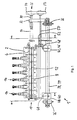
- the application head 1 has a metallic base body 2 and one with a not shown adhesive source connectable fluid supply channel 4, as cylindrical bore is formed in the base body 2 and on which a flexible Adhesive line is connected.
- the main body has an upper part 3 and a lower part 5, which are bolted together.
- a cylindrical one Distribution channel 6 is disposed within the base body 2, which is like the Fluid supply channel 2 over the entire length of the applicator head 1 extends.
- the Distributor channel 6 is half as a semi-cylindrical recess in the upper part 3 and the other half in the lower part 5 as a semi-cylindrical recess formed so that the distribution channel 6 can be easily cleaned.
- a Slot nozzle assembly 10 The slot 8 opens into an elongated outlet opening 12, emerges from the adhesive during operation and then on the substrate is transmitted.
- Each order valve 14 is in the embodiment as pneumatically actuated Valve formed and each has a needle 16, which is in one with a Cylinder is arranged movably arranged pressure gas piston and upon application of the piston with pressure differences up and down is movable.
- the lower Section of the needle 16 cooperates with a formed on the base body 2 Valve seat.
- a vertical connection hole formed in the closed position of the application valve from the tip of the needle 16th closed and opened in the open position of the needle 16.
- Each Order valve 14 is associated with a connecting hole. In not shown Way, the order valves 14 are connected to compressed gas lines.
- a closure body 18 is in the slot 8 of the slot nozzle assembly 10 is movably arranged and seals the slot laterally.
- the closure body 18 is rigid with a cylindrical piston 20th coupled, which is arranged axially movable within the distribution channel 6. Of the Closure body 18 extends from the piston 20 to the outlet opening 12th the slot nozzle arrangement 10.
- the piston 20 has an outer casing 22 on, which is mounted on a threaded sleeve 24.
- the threaded sleeve 24 is part of an adjusting device 26 for varying the length of the slot 8 by displacement of the closure body 18 in the slot eighth together with the piston 20 in the distribution channel 6.
- the adjusting device 26 further includes a rotatably mounted by means of two ball bearings 28 threaded spindle 30th on, with its external thread with a formed on the threaded sleeve 24 Internal thread is engaged.
- the ball bearings 28 are embedded in a plate 32.
- a handwheel 34 At the end of the threaded spindle 30 is a handwheel 34 for manual turning and Adjusting the adjusting device 26 attached.
- the main body 2 and thus the entire applicator head 1 is by means of a subsequently explained guiding and adjusting relative to a stationary frame in the direction of the longitudinal axis of the slot 8 of the slot nozzle arrangement 10 back and forth and in different positions lockable mounted.
- the guiding and adjusting device has two at one not shown frame of a production facility attachable carrier 36 and two attached to this parallel cylindrical guide rods 38, 39 and the guide rods 38, 39 enclosing linear guides 40, 42, 44, 46, which are provided with a plurality of rolling elements, along unroll the guide rods 38, 39.
- the lower portion of the main body 2 is with in the linear guides 40, 42, 44, 46 screwed.
- the Guide rods 38, 39 are illustrated with their end portions as shown in FIG. 1, screwed by screws with the carriers 36.
- the linear guides are by means of screwed several elbows with the base body 2.
- the guiding and adjusting device further comprises a rotatable means of ball bearings mounted on the plate 32 threaded spindle 50 with an external thread and one with the external thread of the threaded spindle 50 in engagement, with an elbow 48 (see Fig. 1) screwed threaded body with a Internal thread on.
- Handwheel 54 can be the main body 2 and thus the entire application head. 1 linearly reciprocating depending on the direction of rotation of the handwheel 54. The maximum displacement depends on the length of the guide rods 38, 39 off. Due to the friction between the external thread of the threaded spindle 50 and the internal thread of the threaded body 52 is the main body 2 in each ascertained any position.
- the hand wheels 34 and 54 and the threaded spindle 30 and 50 are arranged on one side relative to the main body 2, so that a simple operation from one side is possible to the length of the slot 8 or to vary the position of the main body 2 and thus the applicator head 1.
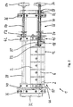
- Figs. 3 to 8 illustrate a substrate guiding device for passing a film or the like at the exit opening 12 the slot nozzle assembly 10 along a defined path of movement.
- the Substrate guiding device has one by means of two pneumatic cylinders 56 pivotable, mounted on the base body 2 frame 58 and two parallel and spaced apart from each other and in turn pivotable together and in different Swiveling positions detectably arranged on the frame 58 Guide elements 60, 62 in the form of guide rods with a polished Surface on.
- the two guide rods 60, 62 are each with their end portions to two Plates 64, 66 mounted about a pivot axis 68 (see Fig. 7) relative to the frame 58 are pivotable. From Figs. 3 and 5 it can be seen that the Frame 58, the plates 64, 66 and the guide elements 60, 62 with the aid of Pneumatic cylinder 56 from a first pivoted position into a second Operating position are pivoted and the substrate by adjusting the Pivoting of the plates 64, 66 and fixing by means of screws in an optimal position for guiding the substrate depending on the application to the Outlet opening 12 can be moved past.
- a pressure roller opposite the outlet opening 12th be arranged.
Landscapes
- Coating Apparatus (AREA)
- Making Paper Articles (AREA)
- Seal Device For Vehicle (AREA)
- Turning (AREA)
- Polarising Elements (AREA)
- Nozzles (AREA)
Applications Claiming Priority (3)
| Application Number | Priority Date | Filing Date | Title |
|---|---|---|---|
| DE29908150U DE29908150U1 (de) | 1999-05-10 | 1999-05-10 | Vorrichtung zum Auftragen von Fluid |
| DE29908150U | 1999-05-10 | ||
| PCT/EP2000/004137 WO2000067914A2 (de) | 1999-05-10 | 2000-05-09 | Vorrichtung zum auftragen von fluid |
Publications (2)
| Publication Number | Publication Date |
|---|---|
| EP1181105A2 EP1181105A2 (de) | 2002-02-27 |
| EP1181105B1 true EP1181105B1 (de) | 2003-10-01 |
Family
ID=8073268
Family Applications (1)
| Application Number | Title | Priority Date | Filing Date |
|---|---|---|---|
| EP00925270A Expired - Lifetime EP1181105B1 (de) | 1999-05-10 | 2000-05-09 | Vorrichtung zum auftragen von fluid |
Country Status (9)
| Country | Link |
|---|---|
| US (1) | US6689214B2 (enExample) |
| EP (1) | EP1181105B1 (enExample) |
| JP (1) | JP4711371B2 (enExample) |
| AT (1) | ATE250983T1 (enExample) |
| AU (1) | AU4404600A (enExample) |
| CA (1) | CA2368115A1 (enExample) |
| DE (2) | DE29908150U1 (enExample) |
| ES (1) | ES2204574T3 (enExample) |
| WO (1) | WO2000067914A2 (enExample) |
Cited By (2)
| Publication number | Priority date | Publication date | Assignee | Title |
|---|---|---|---|---|
| WO2005023435A1 (de) * | 2003-09-02 | 2005-03-17 | Kiener Maschinenbau Gmbh | Stellkörper zur einstellung einer arbeitsbreite eines dosierspaltes |
| DE102006007555B4 (de) | 2006-02-16 | 2019-09-19 | Illinois Tool Works Inc. | Klebstoffauftragsystem und Verfahren zum kontaktlosen Auftragen eines Klebstofffilms auf ein flächiges Substrat |
Families Citing this family (27)
| Publication number | Priority date | Publication date | Assignee | Title |
|---|---|---|---|---|
| DE29921828U1 (de) * | 1999-12-13 | 2000-07-27 | Sm-Klebetechnik Vertriebs GmbH, 52525 Heinsberg | Auftragsvorrichtung |
| DE10205437C1 (de) * | 2002-02-08 | 2003-11-27 | Kiener Maschinenbau Gmbh | Verfahren zur Einstellung einer Arbeitsbreite einer Düsenanordnung zum Auftragen eines fließfähigen Mediums auf eine Materialbahn und Vorrichtung zur Durchführung des Verfahrens |
| ES2211294B1 (es) * | 2002-07-12 | 2005-06-01 | Jesus Francisco Barberan La Torre | Perfeccionamientos en los cabezales de aplicacion de colas termofusibles. |
| DE20308337U1 (de) * | 2003-05-26 | 2003-08-14 | Nordson Corporation, Westlake, Ohio | Vorrichtung zum Auftragen von Fluid |
| DE10330750B4 (de) * | 2003-07-07 | 2005-09-15 | Windmöller & Hölscher Kg | Bodenlegevorrichtung für Papiersäcke |
| DE10330751A1 (de) * | 2003-07-07 | 2005-02-10 | Windmöller & Hölscher Kg | Bodenlegevorrichtung für Papiersäcke |
| DE202004007024U1 (de) | 2004-04-30 | 2004-07-01 | Nordson Corporation, Westlake | Auftragskopf, Auftragsdüsenanordnung, Adapterplatte sowie Montageplatte |
| US7507295B2 (en) * | 2005-03-22 | 2009-03-24 | Nordson Corporation | Adhesive dispenser |
| US8079324B2 (en) * | 2005-10-21 | 2011-12-20 | Robatech Ag | Device for later application of a two-component material on a substrate |
| ES2424166T3 (es) | 2006-09-22 | 2013-09-27 | Nordson Corporation | Aparato para aplicar fluidos tales como adhesivo, en particular adhesivo de fusión en caliente |
| DE202006014743U1 (de) | 2006-09-22 | 2006-11-23 | Nordson Corporation, Westlake | Vorrichtung zum Auftragen von Fluiden wie Klebstoff, insbesondere Schmelzkleber |
| DE202007002156U1 (de) | 2007-02-09 | 2007-04-12 | Nordson Corp | Vorrichtung zum Auftragen von Fluiden wie Klebstoff |
| DE202006019724U1 (de) | 2006-12-29 | 2007-03-01 | Nordson Corporation, Westlake | Vorrichtung mit Schlitzdüsenanordnung zum Abgeben von Fluid |
| DE202007007036U1 (de) | 2007-05-14 | 2007-07-26 | Nordson Corporation, Westlake | Mikrobreitenverstellbare Schlitzdüse |
| US8127711B2 (en) * | 2007-07-05 | 2012-03-06 | Nordson Corporation | Mounting systems for an adhesive application system and methods for applying adhesive |
| DE102008047266A1 (de) | 2008-09-12 | 2010-04-15 | Nordson Corp., Westlake | Vorrichtung zum Auftragen von Fluiden |
| DE202009014160U1 (de) | 2009-10-21 | 2009-12-24 | Nordson Corporation, Westlake | Schlitzdüsenvorrichtung |
| ES2426102T3 (es) | 2010-04-13 | 2013-10-21 | Nordson Corporation | Dispositivo para descargar fluido en un substrato |
| US8640641B2 (en) | 2010-07-02 | 2014-02-04 | Nordson Corporation | Multi-slot applicator with automatic closing function |
| CN102540582A (zh) * | 2012-02-09 | 2012-07-04 | 华映视讯(吴江)有限公司 | 适用于液晶显示面板的涂胶组件 |
| US10259602B2 (en) | 2012-02-28 | 2019-04-16 | The Procter And Gamble Company | Method for forming packages |
| IN2014DN07069A (enExample) | 2012-02-28 | 2015-04-10 | Procter & Gamble | |
| IN2015DN00608A (enExample) | 2012-07-24 | 2015-06-26 | Procter & Gamble | |
| US9783330B2 (en) | 2014-03-06 | 2017-10-10 | The Procter & Gamble Company | Method and apparatus for shaping webs in a vertical form, fill, and sealing system |
| US9643812B2 (en) | 2014-03-06 | 2017-05-09 | The Procter & Gamble Company | Method for pleating or shaping a web |
| IT201600072938A1 (it) * | 2016-07-13 | 2018-01-13 | Devis Bianconi | Dispositivo per strisce depilatorie sagomate e prodotto ottenuto |
| CN109395961B (zh) * | 2018-10-31 | 2020-08-11 | 东莞市爱思宝节能科技有限公司 | 淋涂设备 |
Family Cites Families (28)
| Publication number | Priority date | Publication date | Assignee | Title |
|---|---|---|---|---|
| FR2375839B1 (fr) * | 1977-01-04 | 1980-07-11 | Sofiman Sa | Procede de fabrication d'un article d'habillement et machine pour la mise en oeuvre du procede |
| US4386998A (en) | 1979-08-27 | 1983-06-07 | Acumeter Laboratories, Inc. | Adhesive applicator and method for cigarette-to-filter adhesion and similar applications |
| US4248579A (en) * | 1979-10-10 | 1981-02-03 | Jyohoku Seiko Co., Ltd. | Film extrusion die |
| US4671205A (en) | 1981-07-21 | 1987-06-09 | Billeter Kunstsoffpulver A.G. | Apparatus for applying partial surface coatings |
| US4687137A (en) * | 1986-03-20 | 1987-08-18 | Nordson Corporation | Continuous/intermittent adhesive dispensing apparatus |
| US5435847A (en) | 1989-09-01 | 1995-07-25 | Fuji Photo Film Co., Ltd. | Coating apparatus |
| DE4000405A1 (de) | 1990-01-09 | 1991-07-11 | Hoechst Ag | Verfahren und vorrichtung zum gleichmaessigen aufbringen eines fluids auf eine bewegte materialbahn |
| JP2601365B2 (ja) | 1990-04-13 | 1997-04-16 | 富士写真フイルム株式会社 | 塗布方法 |
| DE4130432C2 (de) | 1991-09-13 | 1995-04-06 | Kuesters Eduard Maschf | Auftragselement für flüssiges, schaumförmiges oder pastenförmiges Auftragsmedium |
| DE9111789U1 (de) | 1991-09-20 | 1991-11-14 | Wako Walzen Konstruktion Systembau GmbH, 4150 Krefeld | Vorrichtung zum kontinuierlichen Auftragen einer Flüssigkeit auf eine Materialbahn |
| JP3021838B2 (ja) * | 1991-09-24 | 2000-03-15 | 三菱化学株式会社 | 塗工ヘッド |
| JPH05200346A (ja) * | 1992-01-29 | 1993-08-10 | Konica Corp | 塗布方法及びスリットコータ |
| KR100272064B1 (ko) * | 1992-10-27 | 2000-12-01 | 미우라 아끼라 | 다이 도장기 |
| US5305955A (en) * | 1993-03-25 | 1994-04-26 | Illinois Tool Works Inc. | Nozzle bar with adjustable pattern |
| JP3599402B2 (ja) * | 1995-01-31 | 2004-12-08 | 株式会社共和 | 押出塗工機 |
| US5674319A (en) * | 1995-02-24 | 1997-10-07 | Avery Dennison Corporation | Die coater and method for applying material to webs of different widths |
| DE29521909U1 (de) | 1995-05-23 | 1998-09-10 | Nordson Corp., Westlake, Ohio | Schlitzdüse |
| JPH0994510A (ja) * | 1995-09-29 | 1997-04-08 | Mitsubishi Chem Corp | ダイコータ及び塗工方法 |
| US5882407A (en) * | 1995-10-03 | 1999-03-16 | Toshiba Battery Co., Ltd. | Apparatus and method for applying a coating to a base material |
| JPH09290194A (ja) * | 1996-04-25 | 1997-11-11 | Sony Corp | 粘性物の塗布ノズルと粘性物の塗布装置 |
| JPH105663A (ja) * | 1996-06-25 | 1998-01-13 | Mitsubishi Chem Corp | ダイコータ |
| JPH105662A (ja) * | 1996-06-25 | 1998-01-13 | Mitsubishi Chem Corp | ダイコータ |
| US5843230A (en) * | 1996-07-02 | 1998-12-01 | Avery Dennison | Sealing system for improved applicator die |
| JP4040144B2 (ja) * | 1996-08-07 | 2008-01-30 | 松下電器産業株式会社 | 塗布装置 |
| JP3143692B2 (ja) * | 1996-10-08 | 2001-03-07 | 井上金属工業株式会社 | 塗工装置 |
| JPH10192762A (ja) * | 1997-01-14 | 1998-07-28 | Kiroku Kobayashi | 粘性流体塗布用の吐出ノズル装置 |
| JP3231660B2 (ja) * | 1997-05-26 | 2001-11-26 | 有限会社福田エンジニアリング | 流動材料の幕状垂れ流し装置 |
| JPH11179260A (ja) * | 1997-12-19 | 1999-07-06 | Fuji Photo Film Co Ltd | 塗布幅変更装置 |
-
1999
- 1999-05-10 DE DE29908150U patent/DE29908150U1/de not_active Expired - Lifetime
-
2000
- 2000-05-09 AU AU44046/00A patent/AU4404600A/en not_active Abandoned
- 2000-05-09 ES ES00925270T patent/ES2204574T3/es not_active Expired - Lifetime
- 2000-05-09 AT AT00925270T patent/ATE250983T1/de not_active IP Right Cessation
- 2000-05-09 DE DE50003910T patent/DE50003910D1/de not_active Expired - Lifetime
- 2000-05-09 CA CA002368115A patent/CA2368115A1/en not_active Abandoned
- 2000-05-09 WO PCT/EP2000/004137 patent/WO2000067914A2/de not_active Ceased
- 2000-05-09 JP JP2000616931A patent/JP4711371B2/ja not_active Expired - Fee Related
- 2000-05-09 EP EP00925270A patent/EP1181105B1/de not_active Expired - Lifetime
-
2001
- 2001-11-09 US US09/986,501 patent/US6689214B2/en not_active Expired - Lifetime
Cited By (2)
| Publication number | Priority date | Publication date | Assignee | Title |
|---|---|---|---|---|
| WO2005023435A1 (de) * | 2003-09-02 | 2005-03-17 | Kiener Maschinenbau Gmbh | Stellkörper zur einstellung einer arbeitsbreite eines dosierspaltes |
| DE102006007555B4 (de) | 2006-02-16 | 2019-09-19 | Illinois Tool Works Inc. | Klebstoffauftragsystem und Verfahren zum kontaktlosen Auftragen eines Klebstofffilms auf ein flächiges Substrat |
Also Published As
| Publication number | Publication date |
|---|---|
| DE50003910D1 (de) | 2003-11-06 |
| US6689214B2 (en) | 2004-02-10 |
| WO2000067914A2 (de) | 2000-11-16 |
| ES2204574T3 (es) | 2004-05-01 |
| EP1181105A2 (de) | 2002-02-27 |
| ATE250983T1 (de) | 2003-10-15 |
| CA2368115A1 (en) | 2000-11-16 |
| WO2000067914A3 (de) | 2001-04-26 |
| US20020026897A1 (en) | 2002-03-07 |
| DE29908150U1 (de) | 1999-08-05 |
| JP2002543967A (ja) | 2002-12-24 |
| JP4711371B2 (ja) | 2011-06-29 |
| AU4404600A (en) | 2000-11-21 |
Similar Documents
| Publication | Publication Date | Title |
|---|---|---|
| EP1181105B1 (de) | Vorrichtung zum auftragen von fluid | |
| EP1358945B2 (de) | Düsenanordnung für eine Vorrichtung zum Auftragen von fliessfähigem Material auf ein Substrat | |
| DE69509578T2 (de) | Ventilvorrichtung und diese Vorrichtung aufweisender Apparat zur Harzbeschichtung | |
| EP2377623B1 (de) | Vorrichtung zum Abgeben von Fluid auf ein Substrat | |
| DE10249726B4 (de) | Flüssigkeitsausgabe-Vorrichtung und Ausgabekopf für eine Flüssigkeitsausgabepistole | |
| EP1205257B1 (de) | Vorrichtung zum flächigen Auftragen von fliessfähigem Klebstoff auf ein relativ zu der Vorrichtung bewegbares Bandmaterial, insbesondere Möbelumleimer | |
| EP0406529B1 (de) | Streicheinrichtung | |
| DE102009019192B4 (de) | Kurzraupenpistole | |
| DE3908453A1 (de) | Verfahren und vorrichtung zum diskontinuierlichen ausbringen von an der luft erstarrenden applikationsfluessigkeiten aus auftragsduesen | |
| DE202006014743U1 (de) | Vorrichtung zum Auftragen von Fluiden wie Klebstoff, insbesondere Schmelzkleber | |
| DE10023672A1 (de) | Vorrichtung zum Auftragen von fließfähigem Material auf ein Substrat sowie Auftragsventil | |
| DE10142074A1 (de) | Spritzbeschichtungseinrichtung | |
| EP0578934A1 (de) | Vorrichtung zum Behandeln von Werkstücken mit einem Druckfluid | |
| DE2145131C3 (de) | Vorrichtung zum gleichmäßigen und stufenlos veränderbaren Einölen von kontinuierlich bewegtem Walzgut, insbesondere von Blechbändern oder -tafeln | |
| DE10023673B4 (de) | Verteilervorrichtung zum Verteilen von Fluiden sowie Vorrichtung zum Abgeben und Auftragen von Fluid, insbesondere Klebstoff | |
| EP2282846A1 (de) | Breitschlitzdüse | |
| EP1501640B1 (de) | Vorrichtung zum auftragen von fluid | |
| DE10345840A1 (de) | Vorrichtung zum Auftragen eines Fluids | |
| EP1240949A2 (de) | Vorrichtung zum Abgeben von Fluiden, insbesondere fliessfähigem Klebstoff | |
| DE20112891U1 (de) | Vorrichtung zum Abgeben von fließfähigem Material auf ein relativ zur Vorrichtung bewegbares Substrat | |
| DE10216972A1 (de) | Vorrichtung und Verfahren zum Abgeben von Fluid auf Substrate, insbesondere von Klebstoff auf mindestens einen Faden | |
| EP1004513B1 (de) | Banderolenbeleimungsvorrichtung und -verfahren | |
| DE202009014160U1 (de) | Schlitzdüsenvorrichtung | |
| DE3115818C2 (enExample) | ||
| DE29918424U1 (de) | Vorrichtung zum Auftragen von Fluid auf ein Substrat |
Legal Events
| Date | Code | Title | Description |
|---|---|---|---|
| PUAI | Public reference made under article 153(3) epc to a published international application that has entered the european phase |
Free format text: ORIGINAL CODE: 0009012 |
|
| AK | Designated contracting states |
Kind code of ref document: A2 Designated state(s): AT BE CH CY DE DK ES FI FR GB GR IE IT LI LU MC NL PT SE |
|
| AX | Request for extension of the european patent |
Free format text: AL;LT;LV;MK;RO;SI |
|
| 17P | Request for examination filed |
Effective date: 20011210 |
|
| GRAH | Despatch of communication of intention to grant a patent |
Free format text: ORIGINAL CODE: EPIDOS IGRA |
|
| GRAS | Grant fee paid |
Free format text: ORIGINAL CODE: EPIDOSNIGR3 |
|
| GRAA | (expected) grant |
Free format text: ORIGINAL CODE: 0009210 |
|
| AK | Designated contracting states |
Kind code of ref document: B1 Designated state(s): AT BE CH CY DE DK ES FI FR GB GR IE IT LI LU MC NL PT SE |
|
| PG25 | Lapsed in a contracting state [announced via postgrant information from national office to epo] |
Ref country code: NL Free format text: LAPSE BECAUSE OF FAILURE TO SUBMIT A TRANSLATION OF THE DESCRIPTION OR TO PAY THE FEE WITHIN THE PRESCRIBED TIME-LIMIT Effective date: 20031001 Ref country code: CY Free format text: LAPSE BECAUSE OF FAILURE TO SUBMIT A TRANSLATION OF THE DESCRIPTION OR TO PAY THE FEE WITHIN THE PRESCRIBED TIME-LIMIT Effective date: 20031001 Ref country code: IE Free format text: LAPSE BECAUSE OF FAILURE TO SUBMIT A TRANSLATION OF THE DESCRIPTION OR TO PAY THE FEE WITHIN THE PRESCRIBED TIME-LIMIT Effective date: 20031001 Ref country code: GB Free format text: LAPSE BECAUSE OF FAILURE TO SUBMIT A TRANSLATION OF THE DESCRIPTION OR TO PAY THE FEE WITHIN THE PRESCRIBED TIME-LIMIT Effective date: 20031001 Ref country code: FI Free format text: LAPSE BECAUSE OF FAILURE TO SUBMIT A TRANSLATION OF THE DESCRIPTION OR TO PAY THE FEE WITHIN THE PRESCRIBED TIME-LIMIT Effective date: 20031001 Ref country code: FR Free format text: LAPSE BECAUSE OF FAILURE TO SUBMIT A TRANSLATION OF THE DESCRIPTION OR TO PAY THE FEE WITHIN THE PRESCRIBED TIME-LIMIT Effective date: 20031001 |
|
| REG | Reference to a national code |
Ref country code: GB Ref legal event code: FG4D Free format text: NOT ENGLISH |
|
| REG | Reference to a national code |
Ref country code: CH Ref legal event code: EP |
|
| REG | Reference to a national code |
Ref country code: IE Ref legal event code: FG4D Free format text: GERMAN |
|
| REF | Corresponds to: |
Ref document number: 50003910 Country of ref document: DE Date of ref document: 20031106 Kind code of ref document: P |
|
| PG25 | Lapsed in a contracting state [announced via postgrant information from national office to epo] |
Ref country code: GR Free format text: LAPSE BECAUSE OF FAILURE TO SUBMIT A TRANSLATION OF THE DESCRIPTION OR TO PAY THE FEE WITHIN THE PRESCRIBED TIME-LIMIT Effective date: 20040101 Ref country code: DK Free format text: LAPSE BECAUSE OF FAILURE TO SUBMIT A TRANSLATION OF THE DESCRIPTION OR TO PAY THE FEE WITHIN THE PRESCRIBED TIME-LIMIT Effective date: 20040101 Ref country code: SE Free format text: LAPSE BECAUSE OF FAILURE TO SUBMIT A TRANSLATION OF THE DESCRIPTION OR TO PAY THE FEE WITHIN THE PRESCRIBED TIME-LIMIT Effective date: 20040101 |
|
| NLV1 | Nl: lapsed or annulled due to failure to fulfill the requirements of art. 29p and 29m of the patents act | ||
| LTIE | Lt: invalidation of european patent or patent extension |
Effective date: 20031001 |
|
| GBV | Gb: ep patent (uk) treated as always having been void in accordance with gb section 77(7)/1977 [no translation filed] |
Effective date: 20031001 |
|
| REG | Reference to a national code |
Ref country code: ES Ref legal event code: FG2A Ref document number: 2204574 Country of ref document: ES Kind code of ref document: T3 |
|
| PG25 | Lapsed in a contracting state [announced via postgrant information from national office to epo] |
Ref country code: LU Free format text: LAPSE BECAUSE OF NON-PAYMENT OF DUE FEES Effective date: 20040509 Ref country code: AT Free format text: LAPSE BECAUSE OF NON-PAYMENT OF DUE FEES Effective date: 20040509 |
|
| PG25 | Lapsed in a contracting state [announced via postgrant information from national office to epo] |
Ref country code: LI Free format text: LAPSE BECAUSE OF NON-PAYMENT OF DUE FEES Effective date: 20040531 Ref country code: BE Free format text: LAPSE BECAUSE OF NON-PAYMENT OF DUE FEES Effective date: 20040531 Ref country code: MC Free format text: LAPSE BECAUSE OF NON-PAYMENT OF DUE FEES Effective date: 20040531 Ref country code: CH Free format text: LAPSE BECAUSE OF NON-PAYMENT OF DUE FEES Effective date: 20040531 |
|
| REG | Reference to a national code |
Ref country code: IE Ref legal event code: FD4D |
|
| PLBE | No opposition filed within time limit |
Free format text: ORIGINAL CODE: 0009261 |
|
| STAA | Information on the status of an ep patent application or granted ep patent |
Free format text: STATUS: NO OPPOSITION FILED WITHIN TIME LIMIT |
|
| 26N | No opposition filed |
Effective date: 20040702 |
|
| EN | Fr: translation not filed | ||
| BERE | Be: lapsed |
Owner name: *NORDSON CORP. Effective date: 20040531 |
|
| REG | Reference to a national code |
Ref country code: CH Ref legal event code: PL |
|
| PG25 | Lapsed in a contracting state [announced via postgrant information from national office to epo] |
Ref country code: PT Free format text: LAPSE BECAUSE OF NON-PAYMENT OF DUE FEES Effective date: 20040301 |
|
| PGFP | Annual fee paid to national office [announced via postgrant information from national office to epo] |
Ref country code: DE Payment date: 20170523 Year of fee payment: 18 |
|
| PGFP | Annual fee paid to national office [announced via postgrant information from national office to epo] |
Ref country code: ES Payment date: 20170627 Year of fee payment: 18 Ref country code: IT Payment date: 20170526 Year of fee payment: 18 |
|
| REG | Reference to a national code |
Ref country code: DE Ref legal event code: R119 Ref document number: 50003910 Country of ref document: DE |
|
| PG25 | Lapsed in a contracting state [announced via postgrant information from national office to epo] |
Ref country code: DE Free format text: LAPSE BECAUSE OF NON-PAYMENT OF DUE FEES Effective date: 20181201 Ref country code: IT Free format text: LAPSE BECAUSE OF NON-PAYMENT OF DUE FEES Effective date: 20180509 |
|
| REG | Reference to a national code |
Ref country code: ES Ref legal event code: FD2A Effective date: 20190913 |
|
| PG25 | Lapsed in a contracting state [announced via postgrant information from national office to epo] |
Ref country code: ES Free format text: LAPSE BECAUSE OF NON-PAYMENT OF DUE FEES Effective date: 20180510 |