EP1173354B1 - Transportsystem mit auf schienen verfahrbarem und kurvengängigen fahrzeug - Google Patents
Transportsystem mit auf schienen verfahrbarem und kurvengängigen fahrzeug Download PDFInfo
- Publication number
- EP1173354B1 EP1173354B1 EP00936634A EP00936634A EP1173354B1 EP 1173354 B1 EP1173354 B1 EP 1173354B1 EP 00936634 A EP00936634 A EP 00936634A EP 00936634 A EP00936634 A EP 00936634A EP 1173354 B1 EP1173354 B1 EP 1173354B1
- Authority
- EP
- European Patent Office
- Prior art keywords
- vehicle
- rails
- transport system
- running gear
- sets
- Prior art date
- Legal status (The legal status is an assumption and is not a legal conclusion. Google has not performed a legal analysis and makes no representation as to the accuracy of the status listed.)
- Expired - Lifetime
Links
- 238000006073 displacement reaction Methods 0.000 description 4
- 230000000977 initiatory effect Effects 0.000 description 2
- 239000000725 suspension Substances 0.000 description 2
- 238000013459 approach Methods 0.000 description 1
- 230000015572 biosynthetic process Effects 0.000 description 1
- 230000036461 convulsion Effects 0.000 description 1
- 230000008878 coupling Effects 0.000 description 1
- 238000010168 coupling process Methods 0.000 description 1
- 238000005859 coupling reaction Methods 0.000 description 1
- 238000012423 maintenance Methods 0.000 description 1
- 238000005096 rolling process Methods 0.000 description 1
- 230000005641 tunneling Effects 0.000 description 1
Images


Classifications
-
- B—PERFORMING OPERATIONS; TRANSPORTING
- B61—RAILWAYS
- B61F—RAIL VEHICLE SUSPENSIONS, e.g. UNDERFRAMES, BOGIES OR ARRANGEMENTS OF WHEEL AXLES; RAIL VEHICLES FOR USE ON TRACKS OF DIFFERENT WIDTH; PREVENTING DERAILING OF RAIL VEHICLES; WHEEL GUARDS, OBSTRUCTION REMOVERS OR THE LIKE FOR RAIL VEHICLES
- B61F3/00—Types of bogies
- B61F3/16—Types of bogies with a separate axle for each wheel
-
- B—PERFORMING OPERATIONS; TRANSPORTING
- B61—RAILWAYS
- B61F—RAIL VEHICLE SUSPENSIONS, e.g. UNDERFRAMES, BOGIES OR ARRANGEMENTS OF WHEEL AXLES; RAIL VEHICLES FOR USE ON TRACKS OF DIFFERENT WIDTH; PREVENTING DERAILING OF RAIL VEHICLES; WHEEL GUARDS, OBSTRUCTION REMOVERS OR THE LIKE FOR RAIL VEHICLES
- B61F5/00—Constructional details of bogies; Connections between bogies and vehicle underframes; Arrangements or devices for adjusting or allowing self-adjustment of wheel axles or bogies when rounding curves
- B61F5/38—Arrangements or devices for adjusting or allowing self- adjustment of wheel axles or bogies when rounding curves, e.g. sliding axles, swinging axles
-
- B—PERFORMING OPERATIONS; TRANSPORTING
- B61—RAILWAYS
- B61F—RAIL VEHICLE SUSPENSIONS, e.g. UNDERFRAMES, BOGIES OR ARRANGEMENTS OF WHEEL AXLES; RAIL VEHICLES FOR USE ON TRACKS OF DIFFERENT WIDTH; PREVENTING DERAILING OF RAIL VEHICLES; WHEEL GUARDS, OBSTRUCTION REMOVERS OR THE LIKE FOR RAIL VEHICLES
- B61F7/00—Rail vehicles equipped for use on tracks of different width
Definitions
- the invention relates to a transport system with one on side by side arranged rails movable and cornering vehicle according to the Preamble of claim 1.
- the German patent DE 32 38 402 is a support chassis for one Monorail to drive an expansion aid for underground tunneling known.
- the monorail has two parallel and spaced apart running rails on which a vehicle of the removal aid can be moved.
- the Vehicle essentially consists of two one behind the other as seen in the direction of travel arranged trolleys, which are connected to each other via a coupling rod.
- On the first trolley is a boom that can be pivoted about a horizontal axis articulated, on the free end of which a traction means engages with one on the second Trolley arranged hoist is connected.
- Each of the two trolleys points four undercarriages, each running horizontally and in the direction of travel Axles are pivotally mounted on the ends of a cross member of the trolley.
- the cross member is in turn around a horizontal axis and in the direction of travel connected to the part of the trolley on which the boom is mounted.
- each undercarriage can be rotated with the Cross member connected.
- one side of the vehicle additionally between the chassis and the cross member essentially horizontal and transverse to the direction of the axis provided that a linear Allow the trolleys to be moved transversely to the direction of travel. Because of the variety the swiveling options provided for each trolley or undercarriage can do that drive the vehicle in question on an irregularly laid rail. By the transverse displaceability of the trolleys' trolleys can also be larger Changes in the track width of the rails can be compensated.
- German patent DE 195 09 727 C1 is a transport system described with a vehicle that can be moved on rails and turns.
- This transport system is not designed as a monorail, but the vehicle drives rails on the floor and has four on his Trolleys arranged on corner points, which are pivoted about vertical axes are.
- the trolleys on one side of the vehicle are not mounted directly on the frame, but over support legs, with their ends facing away from the undercarriage a vertical pivot axis are pivotally mounted on the frame.
- the rails are in the Specially designed curve area. Starting from a largely parallel The course of the rails is the inner rail in the direction of the outer rail retracted that the inner rear landing gear while driving through the Corner area maintains its direction of travel. This is intended to ensure that the speed of the inner, rear chassis while driving through the Although the curve area approaches zero, its direction of movement does not reverses. This means that even tight curve radii can be driven smoothly and with little jerk become.
- DE 39 00 616 A1 describes a transport system with a rail-guided one Vehicle and a switch described.
- the vehicle consists essentially of a rectangular frame, in the corner areas around vertical axes pivotable trolleys are arranged.
- the undercarriages are on side by side and spaced rails movable.
- the rails of different Rail routes preferably cross at right angles. in the Intersection areas are provided to switch vehicles to enable the rail route.
- the switches essentially consist of the crossing points of the rails arranged rail sections by a vertical axis are pivotable. Implementation of a vehicle from a first on a second rail line after the vehicle has entered the switch by moving the pivotable rail sections. This will make the Chassis of the vehicle also swiveled by 90 °, and then that is Vehicle can be moved in the direction of the second rail track.
- the invention has for its object a transport system of the beginning to create the type mentioned, which has optimized possible uses.
- the possibility of a linear displacement of the trolleys one side of the vehicle of the transport system in a direction transverse to Longitudinal direction of travel of the vehicle achieves that on the one hand in Curves running in the longitudinal direction of the vehicle can be traversed and on the other hand also those known from the prior art, in corner / crossing areas arranged switches with around a vertical direction pivotable switch rail sections can be traversed. This extends the possible uses of the vehicles.
- Linear displacement already means a displacement of the undercarriage Longitudinal direction not allowed when locking for lateral travel on a Motor locking can be dispensed with and are only in a particularly simple manner the protrusions and stops described above are required. They can also be Trolleys complete during maintenance work from the transverse ones easily dismantle and assemble the guide elements.
- This vehicle is particularly suitable for use in cross-section I-shaped rails that are held on supports on the floor.
- This transport system is therefore suitable for bypassing mostly in the floor plan right-angled warehouses for general cargo from the individual storage locations record or deliver to them.
- the invention is also for vehicles and Rails suitable in the monorail area.
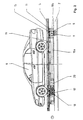
- FIG. 1 shows a top view of a transport system with a curved one Vehicle 1 on a section of two parallel and spaced apart as well Aligned largely parallel to each other at least in the degrees Rails 4.
- the course of the rails 2 shows that on the one hand corner / crossing areas 3 and on the other hand curve areas 4 of the vehicles 1 be driven through.
- the actual vehicle 1 cannot be seen in FIG. 1 because in each case a pallet 5 rests on the vehicles, of which a motor vehicle 6 is transported.
- the vehicles 1 of the Change the longitudinal direction L to the transverse direction Q.
- Rails 2 short switch rail pieces 7 are provided, which are about a vertical axis and essentially 90 ° from the longitudinal direction L in the transverse direction Q and can also be pivoted in the reverse manner as required.
- This Switch rail pieces can be according to DE 39 00 616 A! be trained.
- the pivoting of the switch rail pieces 7 takes place after a vehicle 1 with its undercarriages 8 (see FIG. 2), which also have vertical axes 9 are pivotable, directly on the switch rail pieces 7 for standing come, as well as the axes 9 of the chassis 8 and the pivot axis of the Turnout rail pieces 7 are aligned. So it is possible to go through joint pivoting of the switch rail pieces 7 and the trolleys 8 around in each case 90 ° that the vehicle 1 arriving in the longitudinal direction of travel L passes the corner / intersection area 3 can leave in the transverse direction Q.
- FIG. 2 shows a side view of a vehicle 1 on a straight section a rail 2.
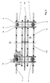
- Figures 3 and 6 each show a top and a Front view of Figure 2. Based on Figures 2 to 4, the Training of the vehicle 1 described in more detail.
- Figure 3 shows that Vehicle a rectangular frame 10 with four parallel and at a distance as well as in Longitudinal direction L extending longitudinal beams 10a, in the area of their in Longitudinal direction L seen front and rear ends over two each Cross members 10 b are interconnected. Only the two inner ones run here Side members 10a over the entire length of the vehicle 1. The two outer side members 10a are in the area between the spaced apart arranged cross members 10b broken.
- the trolleys 11 essentially exist from an impeller 12 (see FIG. 4) which run on the surface of the rail 2.
- the Rail 2 is supported by a support 13 on the floor 14 of a hall.
- Each roller 12 is pivotally mounted about a vertical axis 9.
- Figure 2 is closed derive that the suspension of the trolleys via a on the cross members 10b arranged connecting plate 15 takes place.
- connection plate 15 is to enable transverse displacement of the left undercarriages 8 via guide elements 11 mounted on the upper sides of the crossbeam 10b. This Guide elements 11 only allow the carriages 8 to be moved transversely Longitudinal direction L and not in the longitudinal direction L.
- FIGS. 2 and 3 show that on the longitudinal beams 10a Support rollers 19 are provided on which the pallet 5 rests with the motor vehicle 6.
- the pallet 5 is in this case a lock, not shown, on the idlers 19 and thus held on the vehicle 1.
- FIGS. 2 and 3 show that a chassis is driven by a drive motor 20 which is connected to a chassis 8 is flanged.
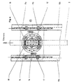
- FIG. 4 shows that along the i-shaped Rails 21 run through which the drive motor 20 with energy is supplied.
- FIGS. 4 and 5 each show an enlarged section of Figure 3 from the area of a chassis when driving longitudinally or crosswise Vehicle 1. From Figures 4 and 5 is the more detailed structure of the Take guide element 11.
- This guide element 11 consists in Essentially consisting of a guide rail 11a, which is on the top of the cross member 10b is screwed on, and of sliding elements 11b which guide rail reach around, are movable along this and on that of the guide rail 11a opposite side are connected to the connecting plate 15.
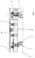
- FIG. 6 shows a chassis 8 during the transverse travel of a vehicle 1.
- the undercarriage 8 is 90 ° around it
- Axis 9 pivots and the projections 16 lie on adjustable Stop elements 17, which are connected to the cross members 10b. This is ensures that the movement of the vehicle 1 in the longitudinal direction L Desired compensation or cross-shift possibility of the chassis 8 of the left Side of the vehicle 1 is lifted in the transverse travel.
- the chassis 8 is also at Travel in the transverse direction Q held in a defined position. This is necessary because the track spacing of the wheels 12 when entering a connecting corner / intersection area with pivotable switch rail pieces 7, the wheelbase is not may change.
Landscapes
- Engineering & Computer Science (AREA)
- Mechanical Engineering (AREA)
- Platform Screen Doors And Railroad Systems (AREA)
- Handcart (AREA)
- Chain Conveyers (AREA)
Description
- Figur 1
- eine Draufsicht auf ein Transportsystem mit einem kurvengängigen Fahrzeug auf einem Schienenabschnitt,
- Figur 2
- eine Seitenansicht auf ein kurvengängiges Fahrzeug,
- Figur 3
- eine Draufsicht von Fig. 2,
- Figur 4
- eine Vorderansicht von Fig. 2,
- Figur 5
- eine Ausschnittsvergrößerung von Figur 3 aus dem Bereich eines Fahrwerkes bei Längsfahrt des Fahrzeuges und
- Figur 6
- eine Ausschnittsvergrößerung von Figur 3 aus dem Bereich eines Fahrwerkes bei Querfahrt des Fahrzeuges.
- 1
- Fahrzeug
- 2
- Schiene
- 3
- Eck-/Kreuzungsbereich
- 4
- Kurvenbereich
- 5
- Palette
- 6
- Kraftfahrzeug
- 7
- Weichen-Drehschienen
- 8
- Fahrwerke
- 9
- Achsen
- 10
- Rahmen
- 10a
- Längsträger
- 10b
- Querträger
- 11
- Führungselement
- 11a
- Führungsschiene
- 11b
- Gleitelement
- 12
- Laufrad
- 13
- Stütze
- 14
- Boden
- 15
- Verbindungsplatte
- 16
- Vorsprung
- 17
- Anschlagelement
- 18
- Führungsrollen
- 19
- Tragrollen
- 20
- Antriebsmotor
- 21
- Schleifleitungen
- L
- Längsfahrrichtung
- Q
- Querfahrrichtung
Claims (6)
- Transportsystem mit nebeneinander angeordneten Schienen (2) und einem darauf verfahrbaren und kurvengängigen Fahrzeug (1), mit an einem Rahmen angeordneten und um senkrechte Achsen (9) schwenkbaren Fahrwerken (8), wobei in Längsfahrtrichtung (L) gesehen die Fahrwerke (8) an einer Fahrzeugseite relativ zu den Fahrwerken der gegenüberliegenden Fahrzeugseite bewegbar an dem Rahmen gelagert sind,
dadurch gekennzeichnet, daß die Fahrwerke (8) zwischen zwei Anschtagelementen (17) aus einer Längsfahrtstellung um die senktrechte Schwenkachse (9) etwa 90 Grad in eine Querfahrtstellung verschwenkbar sind und die Fahrwerke (8) einer Längsseite des Fahrzeuges (1) mittels Gleitelementen (11b) an horizontalen Führungschienen (10a), die an Querträgern (10b) des Rahmens (10) befestigt sind, quer zur Längsfahrrichtung (Q) des Fahrzeuges (1) linear verschiebbar geführt sind. - Transportsystem nach Anspruch 1,
dadurch gekennzeichnet, dass die Anschlagelemente (17) an den Querträgern (10b) des Rahmens (10) justierbar befestigt sind und mit an den Fahrwerken (8) jeweils nach außen vorstehenden Vorsprüngen (16) zusammenwirken. - Transportsystem nach Anspruch 1 bis 2,
dadurch gekennzeichnet, daß mindestens eines der Fahrwerke (4) über einen Elektroantrieb (13) angetrieben ist, der über an der Schiene (2) angeordnete Schleifleitungen mit Energie versorgt wird. - Transportsystem nach einem der Ansprüche 1 bis 3,
dadurch gekennzeichnet, daß jedes Fahrwerk (4) aus einem Laufrad (11) besteht, das über Führungsrollen (12) an der Schiene (2) geführt ist. - Transportsystem nach einem der Ansprüche 1 bis 4,
dadurch gekennzeichnet, daß die Schienen (2) im Querschnitt I-förmig ausgebildet, über Stützen auf dem Boden abgestützt sind und das Fahrzeug (1) auf den Obergurten (14) der Schienen (2) verfahrbar ist. - Transportsystem nach Anspruch 5,
dadurch gekennzeichnet, daß die Führungsrollen (12) an den Längsseiten der Obergurte (14) verfahrbar sind.
Applications Claiming Priority (3)
| Application Number | Priority Date | Filing Date | Title |
|---|---|---|---|
| DE19920026 | 1999-04-27 | ||
| DE19920026 | 1999-04-27 | ||
| PCT/DE2000/001245 WO2000064722A1 (de) | 1999-04-27 | 2000-04-18 | Transportsystem mit auf schienen verfahrbarem und kurvengängigen fahrzeug |
Publications (2)
| Publication Number | Publication Date |
|---|---|
| EP1173354A1 EP1173354A1 (de) | 2002-01-23 |
| EP1173354B1 true EP1173354B1 (de) | 2003-08-20 |
Family
ID=7906623
Family Applications (1)
| Application Number | Title | Priority Date | Filing Date |
|---|---|---|---|
| EP00936634A Expired - Lifetime EP1173354B1 (de) | 1999-04-27 | 2000-04-18 | Transportsystem mit auf schienen verfahrbarem und kurvengängigen fahrzeug |
Country Status (7)
| Country | Link |
|---|---|
| US (1) | US6668737B1 (de) |
| EP (1) | EP1173354B1 (de) |
| AT (1) | ATE247574T1 (de) |
| BR (1) | BR0010148A (de) |
| DE (1) | DE50003368D1 (de) |
| ES (1) | ES2204612T3 (de) |
| WO (1) | WO2000064722A1 (de) |
Families Citing this family (2)
| Publication number | Priority date | Publication date | Assignee | Title |
|---|---|---|---|---|
| US20080240900A1 (en) * | 2007-03-29 | 2008-10-02 | Eric Reisenauer | System for storage and retrieval |
| US9186799B2 (en) | 2011-07-13 | 2015-11-17 | Brooks Automation, Inc. | Compact direct drive spindle |
Family Cites Families (10)
| Publication number | Priority date | Publication date | Assignee | Title |
|---|---|---|---|---|
| GB755005A (en) | 1953-12-03 | 1956-08-15 | Tichauer S A R L M | Improvements in or relating to means for effecting variation in the wheel gauge of rail vehicles |
| US3356040A (en) * | 1964-05-11 | 1967-12-05 | Borgs Fabriks Ab | Device for conveyor systems |
| JPS56105474U (de) * | 1980-01-16 | 1981-08-17 | ||
| DE3238402C2 (de) | 1982-10-16 | 1984-08-09 | Maschinenfabrik Scharf Gmbh, 4700 Hamm | Stützfahrwerk zum Verfahren einer Ausbauhilfe für den untertägigen Streckenvortrieb an einer Hängebahn |
| US4583462A (en) * | 1983-07-15 | 1986-04-22 | Si Handling Systems, Inc. | Driverless vehicle for two way accumulation |
| DE3900616B4 (de) | 1988-01-21 | 2005-06-23 | Volkswagen Ag | Transportsystem mit einem schienengeführten Fahrzeug und einer Weiche |
| US5001987A (en) * | 1988-06-29 | 1991-03-26 | Heico Inc. | Lightweight car-on-track system |
| DE19509727C1 (de) * | 1995-03-13 | 1996-08-14 | Mannesmann Ag | Transportsystem mit auf Schienen verfahrbarem und kurvengängigem Fahrzeug |
| US6138575A (en) * | 1996-12-23 | 2000-10-31 | Aft Automatisierungs- Und Fordertechnik Gmbh | Floor transport system with rail-mounted floor transport vehicles |
| US5857413A (en) * | 1997-01-16 | 1999-01-12 | Ward; Glen N. | Method and apparatus for automated powered pallet |
-
2000
- 2000-04-18 BR BR0010148-6A patent/BR0010148A/pt not_active Application Discontinuation
- 2000-04-18 US US10/031,271 patent/US6668737B1/en not_active Expired - Fee Related
- 2000-04-18 DE DE50003368T patent/DE50003368D1/de not_active Expired - Lifetime
- 2000-04-18 AT AT00936634T patent/ATE247574T1/de not_active IP Right Cessation
- 2000-04-18 EP EP00936634A patent/EP1173354B1/de not_active Expired - Lifetime
- 2000-04-18 WO PCT/DE2000/001245 patent/WO2000064722A1/de not_active Ceased
- 2000-04-18 ES ES00936634T patent/ES2204612T3/es not_active Expired - Lifetime
Also Published As
| Publication number | Publication date |
|---|---|
| EP1173354A1 (de) | 2002-01-23 |
| ATE247574T1 (de) | 2003-09-15 |
| US6668737B1 (en) | 2003-12-30 |
| WO2000064722A1 (de) | 2000-11-02 |
| ES2204612T3 (es) | 2004-05-01 |
| BR0010148A (pt) | 2002-01-15 |
| DE50003368D1 (de) | 2003-09-25 |
Similar Documents
| Publication | Publication Date | Title |
|---|---|---|
| EP1395450B1 (de) | Kombifahrzeug zur nutzung unterschiedlicher fahrwege | |
| DE1294405B (de) | Fuehrungssystem fuer Fahrzeuge mit luftbereiften Laufraedern und Fuehrungsraedern mit vertikaler Achse | |
| EP0834459A1 (de) | Containertransportsystem mit Schienen | |
| EP1531135B1 (de) | Schienengeführtes Transportsystem für Container | |
| EP0588455B1 (de) | Fördersystem mit einem an Leitschienen geführten Flurförderzeug | |
| DE3522918C2 (de) | ||
| DE2100854A1 (de) | Fördereinrichtung mit einem schienen geführten Fahr oder Forderzeug | |
| DE102011002334A1 (de) | Strohmabnehmersystem für ein Fahrzeug | |
| EP0576891B1 (de) | Schienenschleifmaschine | |
| DE19709034C1 (de) | Containertransportsystem mit Schienen | |
| EP0298341A1 (de) | Regalfördersystem | |
| DE2942839C2 (de) | ||
| DE3009643C2 (de) | ||
| EP1173354B1 (de) | Transportsystem mit auf schienen verfahrbarem und kurvengängigen fahrzeug | |
| DE3009900C2 (de) | Fördereinrichtung für Lasten | |
| EP0732246B1 (de) | Transportsystem mit auf Schienen verfahrbarem und kurvengängigem Fahrzeug | |
| DE1405528C3 (de) | ||
| DE2309088A1 (de) | Stadt- und/oder ueberland-linientransportmittel | |
| DE4309501A1 (de) | Anlage zur Endmontage von Automobilen | |
| EP0264616B1 (de) | Leiteinrichtung für ein schienengeführtes Fahrzeug | |
| DE10331773A1 (de) | Lenkbares Trägerfahrzeug | |
| DE3737750C1 (en) | Switch arrangement | |
| DE3920344A1 (de) | Transportvorrichtung | |
| DE2517884A1 (de) | Einschienenbahn | |
| DE1405528B2 (de) | Schienengebundene Fördereinrichtung |
Legal Events
| Date | Code | Title | Description |
|---|---|---|---|
| PUAI | Public reference made under article 153(3) epc to a published international application that has entered the european phase |
Free format text: ORIGINAL CODE: 0009012 |
|
| 17P | Request for examination filed |
Effective date: 20011018 |
|
| AK | Designated contracting states |
Kind code of ref document: A1 Designated state(s): AT BE CH CY DE DK ES FI FR GB GR IE IT LI LU MC NL PT SE |
|
| RAP1 | Party data changed (applicant data changed or rights of an application transferred) |
Owner name: SIEMENS AKTIENGESELLSCHAFT |
|
| GRAH | Despatch of communication of intention to grant a patent |
Free format text: ORIGINAL CODE: EPIDOS IGRA |
|
| GRAS | Grant fee paid |
Free format text: ORIGINAL CODE: EPIDOSNIGR3 |
|
| GRAA | (expected) grant |
Free format text: ORIGINAL CODE: 0009210 |
|
| AK | Designated contracting states |
Designated state(s): AT BE CH CY DE DK ES FI FR GB GR IE IT LI LU MC NL PT SE |
|
| PG25 | Lapsed in a contracting state [announced via postgrant information from national office to epo] |
Ref country code: IT Free format text: LAPSE BECAUSE OF FAILURE TO SUBMIT A TRANSLATION OF THE DESCRIPTION OR TO PAY THE FEE WITHIN THE PRESCRIBED TIME-LIMIT;WARNING: LAPSES OF ITALIAN PATENTS WITH EFFECTIVE DATE BEFORE 2007 MAY HAVE OCCURRED AT ANY TIME BEFORE 2007. THE CORRECT EFFECTIVE DATE MAY BE DIFFERENT FROM THE ONE RECORDED. Effective date: 20030820 Ref country code: NL Free format text: LAPSE BECAUSE OF FAILURE TO SUBMIT A TRANSLATION OF THE DESCRIPTION OR TO PAY THE FEE WITHIN THE PRESCRIBED TIME-LIMIT Effective date: 20030820 Ref country code: FI Free format text: LAPSE BECAUSE OF FAILURE TO SUBMIT A TRANSLATION OF THE DESCRIPTION OR TO PAY THE FEE WITHIN THE PRESCRIBED TIME-LIMIT Effective date: 20030820 Ref country code: IE Free format text: LAPSE BECAUSE OF FAILURE TO SUBMIT A TRANSLATION OF THE DESCRIPTION OR TO PAY THE FEE WITHIN THE PRESCRIBED TIME-LIMIT Effective date: 20030820 Ref country code: CY Free format text: LAPSE BECAUSE OF FAILURE TO SUBMIT A TRANSLATION OF THE DESCRIPTION OR TO PAY THE FEE WITHIN THE PRESCRIBED TIME-LIMIT Effective date: 20030820 |
|
| REG | Reference to a national code |
Ref country code: GB Ref legal event code: FG4D Free format text: NOT ENGLISH |
|
| REG | Reference to a national code |
Ref country code: CH Ref legal event code: EP |
|
| REG | Reference to a national code |
Ref country code: IE Ref legal event code: FG4D Free format text: GERMAN |
|
| REF | Corresponds to: |
Ref document number: 50003368 Country of ref document: DE Date of ref document: 20030925 Kind code of ref document: P |
|
| PG25 | Lapsed in a contracting state [announced via postgrant information from national office to epo] |
Ref country code: DK Free format text: LAPSE BECAUSE OF FAILURE TO SUBMIT A TRANSLATION OF THE DESCRIPTION OR TO PAY THE FEE WITHIN THE PRESCRIBED TIME-LIMIT Effective date: 20031120 Ref country code: GR Free format text: LAPSE BECAUSE OF FAILURE TO SUBMIT A TRANSLATION OF THE DESCRIPTION OR TO PAY THE FEE WITHIN THE PRESCRIBED TIME-LIMIT Effective date: 20031120 |
|
| REG | Reference to a national code |
Ref country code: SE Ref legal event code: TRGR |
|
| GBT | Gb: translation of ep patent filed (gb section 77(6)(a)/1977) | ||
| PG25 | Lapsed in a contracting state [announced via postgrant information from national office to epo] |
Ref country code: PT Free format text: LAPSE BECAUSE OF FAILURE TO SUBMIT A TRANSLATION OF THE DESCRIPTION OR TO PAY THE FEE WITHIN THE PRESCRIBED TIME-LIMIT Effective date: 20040120 |
|
| NLV1 | Nl: lapsed or annulled due to failure to fulfill the requirements of art. 29p and 29m of the patents act | ||
| REG | Reference to a national code |
Ref country code: IE Ref legal event code: FD4D |
|
| PG25 | Lapsed in a contracting state [announced via postgrant information from national office to epo] |
Ref country code: AT Free format text: LAPSE BECAUSE OF NON-PAYMENT OF DUE FEES Effective date: 20040418 Ref country code: LU Free format text: LAPSE BECAUSE OF NON-PAYMENT OF DUE FEES Effective date: 20040418 |
|
| PG25 | Lapsed in a contracting state [announced via postgrant information from national office to epo] |
Ref country code: CH Free format text: LAPSE BECAUSE OF NON-PAYMENT OF DUE FEES Effective date: 20040430 Ref country code: MC Free format text: LAPSE BECAUSE OF NON-PAYMENT OF DUE FEES Effective date: 20040430 Ref country code: LI Free format text: LAPSE BECAUSE OF NON-PAYMENT OF DUE FEES Effective date: 20040430 |
|
| REG | Reference to a national code |
Ref country code: ES Ref legal event code: FG2A Ref document number: 2204612 Country of ref document: ES Kind code of ref document: T3 |
|
| ET | Fr: translation filed | ||
| PLBE | No opposition filed within time limit |
Free format text: ORIGINAL CODE: 0009261 |
|
| STAA | Information on the status of an ep patent application or granted ep patent |
Free format text: STATUS: NO OPPOSITION FILED WITHIN TIME LIMIT |
|
| 26N | No opposition filed |
Effective date: 20040524 |
|
| REG | Reference to a national code |
Ref country code: CH Ref legal event code: PL |
|
| PGFP | Annual fee paid to national office [announced via postgrant information from national office to epo] |
Ref country code: GB Payment date: 20060411 Year of fee payment: 7 |
|
| PGFP | Annual fee paid to national office [announced via postgrant information from national office to epo] |
Ref country code: BE Payment date: 20060419 Year of fee payment: 7 |
|
| PGFP | Annual fee paid to national office [announced via postgrant information from national office to epo] |
Ref country code: FR Payment date: 20060425 Year of fee payment: 7 |
|
| PGFP | Annual fee paid to national office [announced via postgrant information from national office to epo] |
Ref country code: SE Payment date: 20060511 Year of fee payment: 7 |
|
| PGFP | Annual fee paid to national office [announced via postgrant information from national office to epo] |
Ref country code: ES Payment date: 20060516 Year of fee payment: 7 |
|
| GBPC | Gb: european patent ceased through non-payment of renewal fee |
Effective date: 20070418 |
|
| BERE | Be: lapsed |
Owner name: *SIEMENS A.G. Effective date: 20070430 |
|
| PG25 | Lapsed in a contracting state [announced via postgrant information from national office to epo] |
Ref country code: BE Free format text: LAPSE BECAUSE OF NON-PAYMENT OF DUE FEES Effective date: 20070430 |
|
| PG25 | Lapsed in a contracting state [announced via postgrant information from national office to epo] |
Ref country code: GB Free format text: LAPSE BECAUSE OF NON-PAYMENT OF DUE FEES Effective date: 20070418 |
|
| PG25 | Lapsed in a contracting state [announced via postgrant information from national office to epo] |
Ref country code: SE Free format text: LAPSE BECAUSE OF NON-PAYMENT OF DUE FEES Effective date: 20070419 |
|
| REG | Reference to a national code |
Ref country code: ES Ref legal event code: FD2A Effective date: 20070419 |
|
| PG25 | Lapsed in a contracting state [announced via postgrant information from national office to epo] |
Ref country code: FR Free format text: LAPSE BECAUSE OF NON-PAYMENT OF DUE FEES Effective date: 20070430 |
|
| PG25 | Lapsed in a contracting state [announced via postgrant information from national office to epo] |
Ref country code: ES Free format text: LAPSE BECAUSE OF NON-PAYMENT OF DUE FEES Effective date: 20070419 |
|
| PGFP | Annual fee paid to national office [announced via postgrant information from national office to epo] |
Ref country code: DE Payment date: 20130620 Year of fee payment: 14 |
|
| REG | Reference to a national code |
Ref country code: DE Ref legal event code: R119 Ref document number: 50003368 Country of ref document: DE |
|
| REG | Reference to a national code |
Ref country code: DE Ref legal event code: R119 Ref document number: 50003368 Country of ref document: DE Effective date: 20141101 |
|
| PG25 | Lapsed in a contracting state [announced via postgrant information from national office to epo] |
Ref country code: DE Free format text: LAPSE BECAUSE OF NON-PAYMENT OF DUE FEES Effective date: 20141101 |