EP1171269B1 - Formstation - Google Patents
Formstation Download PDFInfo
- Publication number
- EP1171269B1 EP1171269B1 EP00926891A EP00926891A EP1171269B1 EP 1171269 B1 EP1171269 B1 EP 1171269B1 EP 00926891 A EP00926891 A EP 00926891A EP 00926891 A EP00926891 A EP 00926891A EP 1171269 B1 EP1171269 B1 EP 1171269B1
- Authority
- EP
- European Patent Office
- Prior art keywords
- guide plates
- forming station
- station according
- adjustable
- width
- Prior art date
- Legal status (The legal status is an assumption and is not a legal conclusion. Google has not performed a legal analysis and makes no representation as to the accuracy of the status listed.)
- Expired - Lifetime
Links
- 230000007480 spreading Effects 0.000 claims abstract description 81
- 238000003892 spreading Methods 0.000 claims abstract description 81
- 239000000463 material Substances 0.000 claims abstract description 60
- 239000000835 fiber Substances 0.000 claims description 7
- 238000013461 design Methods 0.000 claims description 6
- 210000000629 knee joint Anatomy 0.000 claims description 4
- 210000003127 knee Anatomy 0.000 claims description 3
- 239000004033 plastic Substances 0.000 claims description 3
- 229920003023 plastic Polymers 0.000 claims description 3
- 238000005299 abrasion Methods 0.000 claims description 2
- 239000002131 composite material Substances 0.000 claims description 2
- 238000010276 construction Methods 0.000 claims description 2
- 239000002184 metal Substances 0.000 claims description 2
- 229910052751 metal Inorganic materials 0.000 claims description 2
- 238000005260 corrosion Methods 0.000 claims 1
- 230000007797 corrosion Effects 0.000 claims 1
- 230000000630 rising effect Effects 0.000 claims 1
- 230000009969 flowable effect Effects 0.000 abstract 1
- 241000273930 Brevoortia tyrannus Species 0.000 description 11
- 238000009826 distribution Methods 0.000 description 9
- 230000008859 change Effects 0.000 description 8
- 239000011094 fiberboard Substances 0.000 description 8
- 238000004519 manufacturing process Methods 0.000 description 8
- 230000035508 accumulation Effects 0.000 description 6
- 238000009825 accumulation Methods 0.000 description 6
- 230000007246 mechanism Effects 0.000 description 6
- 229920002522 Wood fibre Polymers 0.000 description 5
- 230000008901 benefit Effects 0.000 description 5
- 238000000465 moulding Methods 0.000 description 5
- 239000004745 nonwoven fabric Substances 0.000 description 5
- 239000002025 wood fiber Substances 0.000 description 5
- 239000011230 binding agent Substances 0.000 description 4
- 230000001360 synchronised effect Effects 0.000 description 4
- 239000011093 chipboard Substances 0.000 description 3
- 239000000109 continuous material Substances 0.000 description 3
- 238000000034 method Methods 0.000 description 3
- 230000008569 process Effects 0.000 description 3
- 238000000576 coating method Methods 0.000 description 2
- 230000008878 coupling Effects 0.000 description 2
- 238000010168 coupling process Methods 0.000 description 2
- 238000005859 coupling reaction Methods 0.000 description 2
- 238000006073 displacement reaction Methods 0.000 description 2
- 239000002657 fibrous material Substances 0.000 description 2
- 230000006870 function Effects 0.000 description 2
- 239000002245 particle Substances 0.000 description 2
- 238000003825 pressing Methods 0.000 description 2
- 230000009467 reduction Effects 0.000 description 2
- 239000000126 substance Substances 0.000 description 2
- 239000002023 wood Substances 0.000 description 2
- 229930091051 Arenine Natural products 0.000 description 1
- 244000003416 Asparagus officinalis Species 0.000 description 1
- 235000005340 Asparagus officinalis Nutrition 0.000 description 1
- 206010010774 Constipation Diseases 0.000 description 1
- 241000196324 Embryophyta Species 0.000 description 1
- 229910000831 Steel Inorganic materials 0.000 description 1
- 230000001154 acute effect Effects 0.000 description 1
- 230000006978 adaptation Effects 0.000 description 1
- 230000002411 adverse Effects 0.000 description 1
- 238000013459 approach Methods 0.000 description 1
- 230000015572 biosynthetic process Effects 0.000 description 1
- 229920002678 cellulose Polymers 0.000 description 1
- 239000001913 cellulose Substances 0.000 description 1
- 239000003795 chemical substances by application Substances 0.000 description 1
- 238000011109 contamination Methods 0.000 description 1
- 238000011161 development Methods 0.000 description 1
- 230000018109 developmental process Effects 0.000 description 1
- 238000009792 diffusion process Methods 0.000 description 1
- 239000000428 dust Substances 0.000 description 1
- 230000007613 environmental effect Effects 0.000 description 1
- 239000003292 glue Substances 0.000 description 1
- 230000005484 gravity Effects 0.000 description 1
- 238000009499 grossing Methods 0.000 description 1
- 239000004922 lacquer Substances 0.000 description 1
- 230000007774 longterm Effects 0.000 description 1
- 150000002739 metals Chemical class 0.000 description 1
- 239000000203 mixture Substances 0.000 description 1
- 230000002265 prevention Effects 0.000 description 1
- 230000006641 stabilisation Effects 0.000 description 1
- 238000011105 stabilization Methods 0.000 description 1
- 239000010959 steel Substances 0.000 description 1
- 239000000725 suspension Substances 0.000 description 1
- 238000012549 training Methods 0.000 description 1
- 230000007704 transition Effects 0.000 description 1
- 238000005303 weighing Methods 0.000 description 1
Images








Classifications
-
- B—PERFORMING OPERATIONS; TRANSPORTING
- B27—WORKING OR PRESERVING WOOD OR SIMILAR MATERIAL; NAILING OR STAPLING MACHINES IN GENERAL
- B27N—MANUFACTURE BY DRY PROCESSES OF ARTICLES, WITH OR WITHOUT ORGANIC BINDING AGENTS, MADE FROM PARTICLES OR FIBRES CONSISTING OF WOOD OR OTHER LIGNOCELLULOSIC OR LIKE ORGANIC MATERIAL
- B27N3/00—Manufacture of substantially flat articles, e.g. boards, from particles or fibres
- B27N3/08—Moulding or pressing
- B27N3/10—Moulding of mats
- B27N3/14—Distributing or orienting the particles or fibres
-
- B—PERFORMING OPERATIONS; TRANSPORTING
- B27—WORKING OR PRESERVING WOOD OR SIMILAR MATERIAL; NAILING OR STAPLING MACHINES IN GENERAL
- B27N—MANUFACTURE BY DRY PROCESSES OF ARTICLES, WITH OR WITHOUT ORGANIC BINDING AGENTS, MADE FROM PARTICLES OR FIBRES CONSISTING OF WOOD OR OTHER LIGNOCELLULOSIC OR LIKE ORGANIC MATERIAL
- B27N1/00—Pretreatment of moulding material
- B27N1/02—Mixing the material with binding agent
- B27N1/029—Feeding; Proportioning; Controlling
-
- B—PERFORMING OPERATIONS; TRANSPORTING
- B27—WORKING OR PRESERVING WOOD OR SIMILAR MATERIAL; NAILING OR STAPLING MACHINES IN GENERAL
- B27N—MANUFACTURE BY DRY PROCESSES OF ARTICLES, WITH OR WITHOUT ORGANIC BINDING AGENTS, MADE FROM PARTICLES OR FIBRES CONSISTING OF WOOD OR OTHER LIGNOCELLULOSIC OR LIKE ORGANIC MATERIAL
- B27N3/00—Manufacture of substantially flat articles, e.g. boards, from particles or fibres
- B27N3/08—Moulding or pressing
- B27N3/10—Moulding of mats
- B27N3/14—Distributing or orienting the particles or fibres
- B27N3/146—Controlling mat weight distribution
-
- B—PERFORMING OPERATIONS; TRANSPORTING
- B65—CONVEYING; PACKING; STORING; HANDLING THIN OR FILAMENTARY MATERIAL
- B65G—TRANSPORT OR STORAGE DEVICES, e.g. CONVEYORS FOR LOADING OR TIPPING, SHOP CONVEYOR SYSTEMS OR PNEUMATIC TUBE CONVEYORS
- B65G69/00—Auxiliary measures taken, or devices used, in connection with loading or unloading
- B65G69/04—Spreading out the materials conveyed over the whole surface to be loaded; Trimming heaps of loose materials
Definitions
- the invention relates to a forming station for chipboard or fiberboard according to the preamble of claim 1.
- chipboard or fibreboard means free-flowing goods like binders Chips or fibers discharged from a dosing bunker and supplied to a spreading head as a spreading device.
- the chips or fibers become a fleece on a scattering head sprinkled continuously running forming tape and then in one subsequent pressing station formed into a finished plate.
- Such a molding station is from the company brochure "molding station", SP 0208, March 1985 edition from Carl Schenck AG previously known in Darmstadt.
- the glue is glued over discharge rollers Chip or fiber material across the entire width discharged into the dosing bunker and conveyed to a spreading head, to be sprinkled on a ribbon.
- Spreading heads are usually of certain types Arranged width that the chip or nonwoven on a Spread a certain width over the forming belt.
- the excess fleece material will then fed back into the dosing hopper via conveyor devices. Since the returned sheet material already with Binding agents are provided, physical occur during the return and / or chemical changes that affect the final quality adversely affect the plates.
- From DE GM 71 37 773 is a molding station with a spreading head previously known, in which the width of the fleece to be spread is adjustable in the spreading head.
- the width of the fleece to be spread is adjustable in the spreading head.
- the key elements are vertical between a scraper and arranged a metering belt and can laterally towards each other or moved away from each other. This can be on the metering belt a fleece is formed, the width of which is determined by the Displacement of the guide pieces is adjustable.
- the height of the preliminary fleece is determined by the height of the guide pieces.
- This pre-fleece is then broken up by a spreader roller sprinkled on a forming tape arranged below to form a chip fleece, the spreading width by adjustable side walls is adapted to the width of the preliminary fleece. Because with a bandwidth adjustment the bunker walls are not adjustable, the dosing bunker must first be emptied before the lower one Spreading width can be spread further. That’s what happens inevitably to a standstill of the forming station, which is an interruption in production means.
- This funnel device consists of three in the conveying direction rows of several rectangular rows arranged one behind the other Funnel shafts.
- the funnel shafts are separated by two Adjacent vertical sidewalls formed that are inclined sideways are and therefore a narrow outlet gap to below form arranged ribbon.
- the neighboring funnel shafts are at the top with their side walls in the inlet area laterally close together, so that between the side walls adjacent funnel shafts there is no inlet gap. Thereby become parallel through the neighboring funnel shafts juxtaposed strips of oriented beaches placed on the forming belt. Because the individual rows of funnel shafts are laterally offset from each other, creates an evenly oriented placement of strands the ribbon.
- the funnel device extends over the entire width of the forming belt and is evident from one equally wide conveyor belt supplied with strands. Such one Spreading station is only for the production of OSB boards are suitable and can be spread and lateral Alignment also cannot be varied.
- the invention is therefore based on the object of a molding station to create where the total material flow to different Adjust spreading widths or lateral deflections is.
- the invention has the advantage that by a simple change the distances between the baffles are basically any Spreading widths are adjustable. This can be done easily Adaptation to different widths of dosing bunkers, Conveyors, spreading heads and form belts can be achieved. Such a spread adjustment can advantageously also provided after the dosing hopper be so that the subsequent conveyor or the Spreading head is already fed the specified spreading width. In this way, the uniformity of the Scattering can be improved since the spreader is already there the material flow can be fed in the width to be spread.
- the invention also has the advantage that the adjustability several adjacent partial streams Material accumulation at the edges of the plates through the division can be reduced to a minimum to several partial flows. On by simple measures this is a material accumulation avoidable on the outer side edges, which at the same time leads to an even spread.
- a special embodiment of the invention has the advantage that through an oblique arrangement of the baffles to the conveying direction a very even, even distribution of the chips or the fleece is achieved because the inclination Accumulations with the depressions directly under the baffles overlap. This is particularly important when scattering Fiberboard advantageously a subsequent height adjustable Leveling roller usually no longer necessary.
- the inclination is the Baffles can be advantageously achieved in that the Fan chute, for example, narrower or wider than at the rear is set at the front.
- Another special embodiment of the invention has the advantage that by automatically changing the distances of all Baffles to each other or whole groups of baffles in the Any spreading widths can be set. This can without interrupting production even during operation Scattering of a different plate width can be made.
- the special embodiment of the invention also has the advantage that through the mechanical adjustment means and the lever-like Coupling long-term, trouble-free setting operation possible is, although due to significant dust pollution, Heat and chemicals most difficult in plate production Environmental conditions prevail. It is particularly advantageous that through the lever-like coupling of the guide plates by a simple linear movement less lever arms all baffles or Groups of baffles around constant or different Adjustment paths are adjustable in their total width.
- Fig. 1 of the drawing is a molding station with a dosing hopper 1, a fan chute 2 with spreading width adjustment, a spreading device 3 and a forming belt 4 on which the material fleece 5 is sprinkled from free-flowing grit, shown.
- the free-flowing spreading material is temporarily stored in the dosing bunker 1 and distributed over an intended discharge width and discharged down over the entire width of the dosing hopper 1.
- free-flowing grit primarily lignocellulosic and / or different cellulose-containing particles Size such as fibers, chips and the like are provided.
- binders provided wood shavings or wood fibers used with the help a bottom belt 6 and discharge rollers 7 from the dosing hopper 1 are carried out continuously.
- the metering bunker has 1 a width that is at least the maximum plate width corresponds to which are produced on the plant should.
- the chips or fibers are discharged from the dosing hopper 1 and across the entire width via conveying and / or spreading devices 3 sprinkled on the ribbon.
- different panel widths are also required, which can be up to 30% smaller than the largest possible Panel width. That is why after the discharge from the dosing bunker 1 a width-adjustable compartment chute 2 is arranged, by the of the spreading device, which is designed as a spreading head 3 is the chip or fiber material in the desired Width is fed.
- the fan chute 2 consists of a rectangular housing part 8 in which a plurality of parallel guide plates 9 are arranged.
- the Baffles 9 are aligned along the conveying direction and divide the flow into several parallel flows. Thereby several relatively even partial streams arise, individually are to be influenced in order to achieve an optimal distribution on the To reach Formband 4. To such an influence in particular to achieve at least as many in width To provide baffles 9 that at least three substreams arise. In practice, panel widths of up to 3 to 4 meters are common, chute 2 from about eight to thirty parallel flows proved advantageous. To do this contains the fan chute 2 according to FIG. 1 is approximately nine to thirty-one baffles 9 arranged in parallel in the direction of the flow are aligned.
- the direction of conveyance is vertical, around the material particles from the dosing hopper 1 to promote the spreading head 3 arranged below.
- the fan chute 2 can also be at an angle to the vertical direction arranged to be a horizontal conveying component at the same time to achieve.
- the fan chute can at the same time be aligned obliquely to the direction of flow to the flow also divert laterally.
- the guide plates 9 are opposite a stationary housing part 8 pivotally or slidably attached so that the distances the baffles 9 from each other continuously or in stages are adjustable. As a result, the partial flows are at least on the material exit point from the fan chute 3 in the Width changeable.
- the baffles 9 are in their upper Area 10 is pivotally suspended and schematically by means of a lever arm 11 shown with respect to the vertical individually pivotable.
- a lever arm 11 shown with respect to the vertical individually pivotable.
- the baffles 9 can also be arranged transversely be so that by a lateral displacement of the sheets 9th the conveyor width at least in the area of the material exit point is continuously or discontinuously changeable. This is primarily achieved with a reduction the delivery width of the delivery flow also over the entire Width and can not be influenced only at the edge areas.
- the guide plates 9 are designed as flat, one-piece plates, which are both in the area of the material delivery point of the Fan chute 2 and below at the material exit point are bevelled against the horizontal.
- bevel 12 serves to improve the division the partial flows and thus the prevention of material accumulation.
- These bevels 12 can both at an angle also differ in the height of the baffles 9 to the to improve continuous material flow.
- the bevel 12 can be straight, curved, sawtooth-shaped and / or modified from it Shapes can be formed.
- For easily pourable Spreading material can also guide plates 9 at right angles or be square.
- the lower slope 13 of the guide plates 9 can both in the conveying direction falling or increasing. With slightly sticky and fibrous grit has a mutual bevel 13, 15 of the adjacent guide plates 9 as advantageous proven to avoid sticking to the lower edge 13, 15 and a continuous, even flow to reach.
- the lower slope 13, 15 of the guide plates 9 can depending on the nature of the grit as a straight edge with different Rise angles, as a curved edge, as a sawtooth Edge and / or formed in forms modified therefrom his.
- the baffles 9 can also with vibration exciters be coupled so that they with a predetermined Amplitude can be made to vibrate transversely to the conveying direction are, whereby material buildup on the sheets 9 avoided become.
- the housing 8 of the fan chute 2 is telescopic, so that the fan chute 2 also in the longitudinal direction 16, that is is vertically adjustable.
- the guide plates 9 can also be designed telescopically to adapt this to the changed spreading height.
- a spreader Spreading head 3 with several parallel and transverse to the conveying direction 14 arranged spreading rollers 17 attached.
- the spreading rollers 17 are horizontally increasing along the conveying direction 14 Line arranged to even spread and limit height to ensure.
- the spreader rollers 17 are there provided and promote immediately below the fan chute 2 the free-flowing goods preferably the glued wood fibers against the direction of conveyance 14. By rotating the Spreading rollers 17 are simultaneously the wood fibers on the one below continuously running forming tape 4 sprinkled as a nonwoven 5 and a subsequent pre-press station or one Plate press fed.
- Such one Scattering station 3 is primarily for scattering a nonwoven fabric intended for HDF and MDF boards, the diffusion heights of which can vary from approx. 6 to 160 cm. That is why Spreading head 3 is arranged adjustable in height.
- the spreading head 3 is stored at a fixed pivot point 18 and is by a Not shown in detail lifting device 19 on simple Way adjusted in height. With larger stroke ranges a parallel four-point height adjustment is also possible.
- the fan chute 2 is both a conveying and spreading device formed through which the nonwoven fabric 5 directly is applied to the forming belt 4.
- Dosing bunker 1 discharge rollers 7 in their speed as well as adjustable in the angle.
- a belt scale 21a is also integrated control the discharge rate precisely so that a predetermined Is spreadable directly onto the forming belt 4.
- the Belt weigher can also be integrated in the forming belt in order to Spread the spreading amount on the forming belt 4.
- the fan chute 2 is adjustable in height by means of telescopic guide plates 21, so that large fiber height ranges are thereby also possible in a simple manner are spreadable from approx. 6 to 160 cm.
- the baffles 21 in three parts, which in particular by a parallel position in the area of the forming belt 4 enable clean vertical edge scattering and this at a variable width adjustment.
- another Stripping roller 22 is provided which is adjustable so that the predetermined nonwoven surface is evened out.
- the fan chute 2 is between the Dosing hopper 1 and an additional conveying device 23, which feeds the spreading material to a spreading head 24.
- the additional Conveying device 23 is designed as a dosing belt scale, which continuously have an adjustable delivery rate in the Scattering head 24 promotes, so that depending on the plate thickness and width a predeterminable amount from the scattering head 24 onto the forming belt 4 is spreadable.
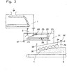
- the fan chute 2 is as in FIGS. 1 and 2 arranged below the dosing hopper and in the conveyor width adjustable.
- the fan chute 2 promotes directly on the continuously driven weigh feeder 23.
- the weigh feeder 23 is provided in a width that is at least corresponds to the maximum spread.
- the dosing belt scale 23 is made in width by side walls 25 on each outer edge limited, which is adjustable according to the spread are designed.
- the width of the side walls follows 25 the width adjustment of the fan chute 2 by the side walls 25 are movable relative to one another or apart.
- the weighing device 26 precise control of the spread rate possible, that of the desired Plate thickness and width corresponds.
- the dosing belt scale in front of the spreading head 24 23 a rapid change in delivery rate even before spreading take place, provided the material density or composition changes, so that always a predetermined fleece weight is exactly observable.
- the additional dosing belt scale 23 is on one side via a bearing element 27 rotatably mounted in order to deal with large differences in spreading height, like in the manufacture of fiberboard, which Make the head adjustable.
- the flow rate is additional through a height-adjustable leveling roller 28 uniform.
- the spreading head 24 contains a plurality of spreading rollers arranged transversely 30, which spread the spreading material onto the forming belt 4 below Sprinkle in a given height and width.
- the default Width largely results from the approach Material width on the dosing belt scale 23, which by the Fan chute 2 was specified. Since the directed towards the spreading head 24 vertical conveyor shaft 31 to the maximum spread dimensioned, could be adjustable in width in it Side plates are provided so that the conveyor width too can be adjusted to the desired spreading width.
- the spreading head 24 is rotatable on an upper bearing element 32 stored so that this by a lifting mechanism, not shown 33 is adjustable in height. This is special an exact spreading height adjustment controllable at the scattering of fiberboard is advantageous.
- the stripping roller 34 is thus an intended material fleece height exactly spreadable, provided that the spreading head 24 is in height is set accordingly.
- the scattered nonwoven fabric 5 is then one by the continuously running forming belt 4 subsequent pre or plate press fed.
- a dosing belt scale 23 is arranged, at the Outflow opening 35 a chute 2 is provided, which Delivery flow in a predeterminable width a spreading head 3 as Spreading device feeds.
- the dosing hopper 1 and the dosing belt scale 23 correspond to the parts described for FIG. 3. However, here is vertical between the dosing belt scale 23 and above the spreading head 3, the fan chute 2 is provided.
- the fan chute 2 is configured here as comparable that already described for FIG. 1.
- the pourable goods such as in particular glued wood fibers
- the spreading head 3 Through the arranged parallel to one another transversely to the conveying direction 14
- Spreading rollers 17 is a nonwoven fabric 5 in on the forming belt 4 specified width and sprinkled to the pre or plate press promoted.
- the spreading head 3 is on one side via a pivot bearing element 18 rotatably mounted so that it has a not shown Lifting device 19 is adjustable in height.
- a fan chute 2 is a sectional view shown.
- the upper arrows 36 indicate the material task in the conveying direction again schematically while below the compartment chute 2 a belt scale 23 as a conveyor located.
- the fan chute 2 consists essentially from a few parallel guide plates 9, all in the conveying direction 36 run.
- the baffles 9 are in the upper area 37 pivotally suspended so that they can be used individually or in Groups are adjustable. With longer compartment chutes 2 can the baffles 9 also through several bearing points 37 with one be fixed housing 8 or frame part connected.
- the baffles 9 can also be arranged laterally displaceable, to the distances between them infinitely or in predefinable To change levels.
- baffles 9 are provided. In practice there have been nine for conveyor widths up to approx. 3 to 4 m up to thirty baffles proved to be advantageous. In individual cases can also be used, for example, for the scattering of chipboard up to fifty baffles 9 can be provided.
- the illustrated Fan chute 2 is designed so that at maximum conveying width all baffles 9 aligned parallel to each other are, so that the total material flow in about eight equal Partial streams 38 is divided.
- changes in the spread of up to approx. 30% may have to be necessary the two edge guide plates 39, 40 to about 60 cm adjustable inwards his. Therefore, both baffle groups are beyond the middle guide plate 41 can be pivoted to the middle guide plate 41, around the conveyor width according to the desired Plate width adjustable.
- baffles 9, 39, 40, 41 can also be arranged so that they are not only inward, but are also or can only be moved outwards. This can then be advantageous if from a relatively narrow Dosing hopper 1 wider plates should be spreadable.
- baffles 39, 40 on the two side edges are up to Conveyor belt 23 connected to side walls 43, 44, which are synchronous are displaceable with the guide plates 39, 40.
- This will in particular with large scattering heights 42 of approximately up to 2 m clean trailing edge formed, which has an exact spread on the forming belt 4. This is particularly advantageous if if according to the training of Fig. 2 the Drawing is conveyed directly onto the forming belt 4.
- the baffles 9, 39, 40, 41 are flat, straight sheets trained, which are made of a thin steel sheet.
- the sheets 9, 39, 40, 41 can also cross to the longitudinal or Conveying direction 36 have a corrugated sheet-like structure in order a longitudinal guidance function, especially with inclined fan chutes To achieve 2.
- the structure can also be a zigzag, have angular or modified shape, all of which also have additional stabilization functions perceive lengthways.
- the baffles 9, 39, 40, 41 can be hardened on their contact surfaces or with harder ones Surface coatings may be provided to prevent abrasion Reduce. So are baffles made of other metals, Plastics or composites can be used.
- the surfaces can also be used with surface coatings that are difficult to adhere made of plastic or comparable materials in particular to prevent dirt and binder buildup avoid.
- the guide plates 9 can also with a vibration exciter coupled, the buildup or contamination loosens or prevents.
- the baffles 9, 39, 40, 41 are rectangular and in the longitudinal direction 36 trained the same length.
- edges 12, 13, 15 proven to be advantageous. In particular, this will result in material jams in the loading area and in the discharge area of the fan chute 2 effectively avoided.
- This task- 12 and Leading edges 13, 15 can also be sawtooth-shaped, curved or be designed in modified shapes. So had it has also proven to be advantageous, especially in the outlet area to design the length of the baffles differently, to enable good tear-off behavior, which ensures a continuous Material flow is guaranteed.
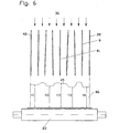
- FIG. 6 of the drawing A further embodiment is shown in FIG. 6 of the drawing, after the all baffles 9, 39, 40, 41 laterally independent can be aligned from each other. Every baffle is there 9, 39, 40, 41 by means of a separate swivel drive 11 or shift drive individually controllable, so that in particular a predetermined height profile 45 with different material heights 46 can be deposited on the conveyor belt 23 or forming belt 4. This is always advantageous when plates with different Densities or profiles are to be produced. In order to can also be adapted to certain pressing characteristics of the subsequent press station can be made. Furthermore can with such a single orientation also a simultaneous one one-sided lateral deflection of the flow rate controlled become.
- a fan chute 2 with in the longitudinal direction three-part guide plates 9, 39, 40 shown, the are articulated together.
- This baffle arrangement causes a cross-section change only in the middle Area 47, so that especially in those at risk of constipation A good material flow can be achieved in transition areas. At the same time, this makes a vertical one in the outlet area 48 Material leakage is achieved, the clean edge formation guaranteed on the underlying form 4 or conveyor belt 23.
- the baffles 9, 39, 40 can also consist of more than three baffle parts exist, so that even rounded material constrictions are controllable. Instead of the multi-part baffles can also be used flexible baffles, the one continuous material transport in conveying direction 36 cause.
- the guide plates can also be telescopic in length be designed so that the fan chute 2 also in the length is adjustable, which is particularly the case with different ones Scattering heights is advantageous.
- the Fan chutes should also be designed so that they only connect to one adapted only predetermined width reduction or enlargement would.
- the guide plates 9 would have to be firmly in the housing or frame part may be arranged. That would be easy a predefined adjustment to a single defined funding or change in spreading width possible.
- a fan chute 51 with in conveying or strip running direction of straight baffles shown schematically as a sectional view.
- the top ones Arrows the material feed point 52 from the not shown Dosing bunker schematically again, while below the fan chute 51 a forming belt 53 with a drive roller 61 is located as a conveyor.
- the fan chute 51 is adjustable in width and consists essentially of several transverse to the vertical adjustable baffles 54, all run straight in the conveying or belt running direction.
- the baffles 54 are pivotally suspended in the upper area, so that they can be adjusted individually or in groups across the vertical are.
- the guide plates 54 can be also through several bearing points with a fixed housing or Frame part to be connected.
- the baffles 54 can also to be arranged laterally displaceable to the distances between to change them continuously or in predefinable levels.
- the fan chute 51 there are nine guide plates 54 intended. In practice, funding widths of around 3 to 4 m with nine to thirty baffles 54 as advantageous proved.
- the fan chute 51 shown is designed so that at maximum conveying width all baffles 54, 56, 57 in parallel are aligned with each other so that the total material flow is divided into approximately eight equal partial streams 55.
- the two edge guide plates 56 be adjustable inside. That is why both baffle groups are beyond the middle baffle 57 to the middle baffle 57 pivotable to the conveyor width corresponding to the desired plate width symmetrically to the belt center.
- baffles 54, 56 are pivoted or shifted be that 58 equal distances at the material exit point the baffles 54, 56, 57 to each other arise in order to overall width a relatively equal material distribution to achieve.
- width adjustment Material distribution achieved on the forming belt 53, which in the Middle of the partial flows 55 over light material accumulations 59 and below the guide plates 54, 56, 57 via small depressions 60 has.
- This inventive arrangement of the guide plates 54, 56, 57 is 9 and 10 of the drawing can be seen schematically.
- 9 of the drawing is a top view of the baffles 54, 57 of the fan chute according to FIG. 8 shown from above, and only half of the mirrored chute 51.
- the fan chute half shown has one Width of about 150 cm, the baffles 54, 56, 57 in one 10 cm apart.
- This Fan chute 51 is suitable for plate widths up to approx. 300 cm.
- All guide plates 54, 56, 57 are in the conveying or belt running direction 62 aligned so that the sprinkled glued Chips or fibers can be divided into parallel partial streams 55 and by gravity down on the forming belt 53 arrive.
- the partial flows 54 through the guide plates 54, 56, 57 of the fan chute 51 partially deflected laterally, so that the accumulations 59 overlap with the recesses 60 so that a flat uniform scattering on the forming belt 53 arises.
- FIG. 10 shows schematically the exit area 58 of the inventive design of the fan chute 51 shows.
- Fig. 10 of the drawing is a width adjustment represented at the material exit point 58 by approximately 25%, so that the exit width of the fan chute 51 only approx. 220 cm or 110 cm per half of the compartment chute shown is.
- the guide bleaches 54, 56, 57 are used for or tape running direction 62 obliquely or laterally offset arranged, in practice a lateral offset of about the width of a partial stream 55 was found to be advantageous Has.
- Such an inclination or lateral offset can be simply by spreading the fan chute 51 set narrower in the conveying direction 62 at the rear is considered front.
- the width adjustment is more advantageous Always symmetrical to the center baffle 57, so that a Even spreading can be achieved even with smaller spreading widths is.
- baffles 54, 56, 57 which in vertical direction approx. 150 cm long and in the conveying or belt running direction 62 are approx. 100 cm wide.
- the bevel angle of the individual guide plates 54, 56, 57 can also be different, especially in the middle Baffles 57 in the front area only a short Guide route to provide different inclinations compensate through short routes.
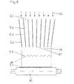
- Fig. 8 of the drawing is a width-adjustable chute shown, in which all the baffles 54, 56, 57 so be pivoted or shifted at the material exit point 58 the guide plates 54, 56, 57 equal distances from each other have a proportionate to the full width to achieve the same material distribution.
- the guide plates 54, 56, 57 equal distances from each other have a proportionate to the full width to achieve the same material distribution.
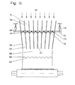
- FIG. 11 of the drawing Width adjustment device shown schematically.
- the single ones Baffles 54, 56, 57 are in the area of the material feed point 52 hinged and in the lower third through the width adjustment device 69, which acts as an articulated lever device is formed, connected to each other.
- the articulated Lever device 69 consists essentially of eight knee lever joints arranged between the separating plates 54, 56, 57 70 and an adjustment lever mechanism 71.
- the toggle joints 70 are formed from two joint arms 72 of equal length, the one with an articulated arm end on a baffle 54, 56 and at the other end articulated on a roller 73 are attached.
- the individual articulated arms 72 have at least one length half the distance of the maximum Distance between the guide plates 54, 56, 57 corresponds. Due to the articulated connection of the knee joints 70 with the Baffles 54, 56, 57 are all baffles 54, 56, 57 mechanical coupled with each other.
- the rollers arranged between the articulated arms 72 73 are arranged in a slotted U-shaped tube, the represents the adjustment mechanism 71.
- the U-profile tube 71 is horizontally and transversely to the conveying or belt running direction in each case arranged at the beginning and end of the fan chute 51.
- to Width adjustment of the compartment chute 51 is the U-shaped tube 71 at each end with a vertical drive, not shown 74 provided by which the adjusting mechanism 71 in both directions vertically adjustable with a linear movement is.
- the vertical drive 74 can be used as a traction screw drive hydraulic or pneumatic pressure medium cylinder or in another form of a linear drive.
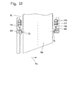
- FIG 12 of the drawing is the side view, which is in conveying or strip running direction 76 arranged guide plates 54, 56, 57 shown with two pull spindle drives 74. It is in each case a similar width adjustment device at the front and rear 69 are arranged, each of which has a spindle drive 77.
- the drive motors 78 are each on a stationary Querholm 79 articulated.
- the in the gear drive motor 78 vertically adjustable tension spindle 80 is on one Flange articulated on which the horizontal U-profile tube 71 is arranged.
- the whole Adjustment device 69 front and rear, each with two Tension spindle drives 77 provided, so that a uniform, trouble-free Height adjustment is guaranteed.
- the traction screw drives 77th evenly move the two U-profile tubes 71 upwards. Thereby becomes the distance between all guide plates 54, 56, 57 automatically reduced evenly, although the lateral adjustment path in the outer guide plates 56 is larger than in the inner baffles 54. With an even height adjustment both front and rear are formed automatically equally wide and narrow sub-streams 55, all of which Baffles 54, 56 parallel to the conveying direction 76 and symmetrical move to the center or center guide plate 57 and only that middle guide plate 57 remains in its position.
- the baffles can 54, 56, 57 can be adjusted so that almost any narrow partial flows 55 at the material exit point 58 form. Since preferably with such a fan chute 51 In practice, fibreboards are scattered, at most one Width adjustment of approx. 30% is required. To do so the partial streams 55 do not narrow downward at an acute angle, otherwise there would be material jams. Therefore baffle lengths of approx. 1.5 to 2 m are provided.
- the Width adjustment device 69 can also be designed such that the four vertical drives 74 can also be controlled individually. This makes it possible, for example, to guide the baffles 54, 56, 57 at the front in a larger one and at the rear in a smaller one Set the distance to each other. This will guide the baffles 54, 56, 57 laterally offset to the conveying direction 76, so that they are then arranged obliquely in the flow. Because the middle Baffle 57 remains unchanged in the conveying direction 76, arises a symmetrical inclination to the center of the fan chute.
- the vertical drives 74 can also be controlled in this way, for example be that the U-shaped tube 71 is inclined in the horizontal is adjustable so that both front and rear different distances between the guide plates 54, 56, 57 result, so that at the same time the inclination of the Baffles 54, 56, 57 can be influenced in the flow.
- the inclination can be chosen such that the Elevations 59 and depressions 60 of the partial flows 55 in the conveying direction 76 overlap in such a way that a very homogeneous, even Spreading surface is accessible.
- the adjustment mechanism 71 can also be designed such that it is in the region of the middle Baffle 57 is divided. Each part of the Adjustment mechanism 71 both vertically adjusted as a whole be hinged or also attached in the middle to it to make this point pivotable.
- FIG. 13 of the drawing Another embodiment is shown in FIG. 13 of the drawing a width adjustment on a fan chute 51 according to FIG. 8 shown.
- This width adjustment there is a uniform change in distance of the guide plates 54, 56, 57 to each other through a so-called scissor-type linkage 83 as articulated Lever device, the change of which by a horizontal Linear movement 86 can be reached.
- at least eighteen adjustment levers 84 in the form of a scissor grid articulated with each other and at the intersection points 85 a guide plate 54, 56, 57 hinged.
- a horizontal Linear drive such as a traction screw drive 77 or the like, the distance between the guide plates 54, 56, 57 can be changed evenly.
- the drive 77 must also be symmetrical Center baffle 57 take place.
- a separate linear drive 77 is provided be a synchronous horizontal movement 86 inwards or caused outside.
- Such a scissor lattice linkage 83 would advantageously on the fan chute 51 in the conveying direction 76 provided both front and rear, whereby with a synchronous control of the linear drives 77 a uniform width adjustment would be achievable.
- Such a thing Scissor lattice linkage 83 can also be designed that it is versus a horizontal line as a whole or around a pivot point is pivotable.
- baffles 54, 56 front and rear can also one Inclined of the guide plates 54, 56 to the conveying direction 76 reached be achieved, whereby a smoothing of the spreading surface can be achieved is.
- FIG. 14 of the drawing an automatic width adjustment on a fan chute 51 shown in FIG. 8 of the drawing.
- the Width adjustment device is as an articulated lever device formed and arranged in the upper region of the fan chute 51 and causes the individual guide plates to pivot 54, 56 opposite a vertical orientation.
- the articulated Lever device consists essentially of two symmetrical parts arranged to the center guide plate 57, each four Articulated lever connections 87 included that are on a common Adjusting lever 89 are articulated and one Represent articulated lever assembly 88.
- the Articulated lever connections 87 each consist of an approximately horizontally aligned lever arm 91 and an approximately vertical aligned lever arm 90.
- the horizontal lever arm 91 is on one end fixed to the fulcrum 92 of the guide plates 54, 56 connected and articulated at the other end to the vertical Lever arm 90 attached.
- the vertical lever arm 90 is included its lower end on the common adjusting lever 89 articulated.
- the adjustment lever 89 is essentially lever 89 is aligned substantially horizontally and in Area of the center guide plate 57 rotatably mounted.
- the other Ends are the adjusting lever 89 with one not closer Drive 93 shown connected, a linear movement generated, and through which the guide plates 59, 56 with respect to the vertical alignment can be pivoted sideways.
- the drives can 93 at the beginning and end of the fan chute 51 also with different ones Pivotal paths can be controlled so that a Inclination of the guide plates 54, 56 with respect to the conveying direction 76 results. It is also conceivable that each half of the compartment chute is controlled separately to any funding differences compensate in the partial flows or surface irregularities. Especially when scattering fiberboard can by the individual control of the drives 93 not only that Width can be changed automatically, but also the surface ripple largely avoided.
- each adjustment lever 89 For an individual control of each adjustment lever 89 are four drives 93 required, with each half of the compartment chute both in front and back automatically in width and thus the baffle position to the conveying direction 76 is also adjustable is.
- articulated lever arrangements 88 of this type are simple with a few linear drives 93 chutes 51 with up to thirty baffles 54, 56, 57 together in width and the Alignment to conveying direction 76 adjustable.
- the Adjustment also takes place automatically during the spreading process, without interrupting the plate making process should be.
Landscapes
- Life Sciences & Earth Sciences (AREA)
- Engineering & Computer Science (AREA)
- Manufacturing & Machinery (AREA)
- Wood Science & Technology (AREA)
- Forests & Forestry (AREA)
- Mechanical Engineering (AREA)
- Dry Formation Of Fiberboard And The Like (AREA)
- Filling Or Emptying Of Bunkers, Hoppers, And Tanks (AREA)
- Saccharide Compounds (AREA)
- Furan Compounds (AREA)
Description
- Fig. 1:
- Eine Formstation mit einer Fächerschurre zwischen einem Dosierbunker und einem Streukopf;
- Fig. 2:
- Eine Formstation mit einer Fächerschurre zwischen einem Dosierbunker und einem Formband;
- Fig. 3:
- Eine Formstation mit einer Fächerschurre zwischen einem Dosierbunker und einer Dosierbandwaage;
- Fig. 4:
- Eine Formstation mit einer Fächerschurre zwischen einer Dosierbandwaage und einem Streukopf;
- Fig. 5:
- Ein Schnittbild der Fächerschurre bei einer Streubreitenverengung;
- Fig. 6:
- Ein Schnittbild der Fächerschurre bei einer Streuprofilanpassung;
- Fig. 7:
- Ein Schnittbild der Fächerschurre mit dreiteiligen Leitblechen;
- Fig. 8:
- ein Schnittbild einer schematisch dargestellten Fächerschurre mit in Förder- oder Bandlaufrichtung gerade ausgerichteten Leitblechen;
- Fig. 9:
- eine Draufsicht auf die Leitbleche der Fächerschurre von oben gesehen;
- Fig. 10:
- eine Draufsicht auf die Leitbleche der Fächerschurre von unten gesehen;
- Fig. 11:
- eine schematische Fächerschurre mit einer Breitenverstellung über ein Kniehebelgestänge;
- Fig. 12:
- eine Fächerschurre in Seitenansicht mit einem höhenverstellbaren Kniehebelgestänge;
- Fig. 13:
- eine schematische Fächerschurre mit einer Breitenverstellung durch ein Scherengittergestänge, und
- Fig. 14:
- eine schematische Fächerschurre mit einer Breitenverstellung über ein Gelenkhebelgestänge.
Claims (25)
- Formstation mit einem Dosierbunker (1) aus dem rieselfähige Güter, insbesondere span- und faserförmige Güter, einer Streuvorrichtung (3, 24) zugeführt werden, durch die ein Materialvlies (5) auf ein Formband (4) aufstreubar ist, wobei zwischen dem Dosierbunker (1) und dem Formband (4, 53) vertikal und längs im Förderstrom eine Fächerschurre (2, 51) vorgesehen ist, die aus mehreren in Förderrichtung (36) nebeneinander angeordneten Leitblechen (9, 39, 40, 41, 54, 56, 57) besteht, die den Förderstrom in Förderrichtung (36, 62, 76) in mehrere Teilströme (38, 55, 56) unterteilen und wobei die benachbarten Leitbleche so beabstandet sind, daß sich zwischen ihnen ein Teilstrom (38, 55, 56) ausbildet.
- Formstation nach Anspruch 1, dadurch gekennzeichnet, daß die Abstände der Leitbleche (9, 39, 40, 41, 54, 56, 57) voneinander und/oder von einer vertikalen Ausrichtung einstellbar sind, wodurch der Förderstrom seitlich umlenkbar und/oder in der Breite verstellbar ist.
- Formstation nach Anspruch 1 oder 2, dadurch gekennzeichnet, daß die Fächerschurre (2, 51) unmittelbar zwischen dem Dosierbunker (1) und dem Formband (4, 53) oder dem Dosierbunker (1) und einer zusätzlichen Fördervorrichtung (23) und/oder der Fördervorrichtung (23) und einem Streukopf (3, 24) oder dem Dosierbunker (1) und dem Streukopf (3, 24) angeordnet ist.
- Formstation nach Anspruch 3, dadurch gekennzeichnet, daß die zusätzliche Fördervorrichtung (23) oder das Bodenband (6) des Dosierbunkers (1) als Dosierbandwaage (21, 23) ausgebildet ist, durch die die zuführbare Materialmenge regelbar ist.
- Formstation nach einem der vorhergehenden Ansprüche, dadurch gekennzeichnet, daß die Fächerschurre (2, 51) mindestens vier Leitbleche (9, 39, 40, 41, 54, 56, 57) enthält, wobei zwei als Seitenbegrenzung (39, 40, 56) dienen.
- Formstation nach einem der vorhergehenden Ansprüche, dadurch gekennzeichnet, daß die Leitbleche (9, 39, 40, 41, 54, 56, 57) verschwenkbar oder verschiebbar gelagert sind, wobei diese mindestens an einem Lagerpunkt (37, 92) quer zur Förderrichtung (36, 62, 76) verschwenkbar und/oder verschiebbar sind.
- Formstation nach einem der vorhergehenden Ansprüche, dadurch gekennzeichnet, daß die Leitbleche (9, 39, 40, 41, 54, 56, 57) einzeln oder in Gruppen steuerbar sind, wobei diese einzeln oder gruppenweise kontinuierlich, diskontinuierlich oder stufenweise aufeinander zu oder voneinander weg bewegbar sind.
- Formstation nach einem der vorhergehenden Ansprüche, dadurch gekennzeichnet, daß die Leitbleche (9, 39, 40, 41, 54, 56, 57) als flache, gerade Bleche ausgebildet sind oder quer zur Längsrichtung (36) wellen- oder sägezahnartig oder in davon abgewandelten Formen strukturiert sind.
- Formstation nach einem der vorhergehenden Ansprüche, dadurch gekennzeichnet, daß die Leitbleche (9, 39, 40, 41, 54, 56, 57) rechteckförmig oder quadratisch ausgebildet sind, oder im Aufgabebereich (12, 52) und/oder Abführbereich (13, 15, 58) über in Förderrichtung (14) oder entgegen der Förderrichtung (14) schräg ansteigende Kanten verfügen, wobei die Kanten gerade, gewölbt, wellen- oder sägezahnförmig verlaufen.
- Formstation nach einem der vorhergehenden Ansprüche, dadurch gekennzeichnet, daß die Leitbleche (9, 39, 40, 41, 54, 56, 57) gleich oder unterschiedlich lang sind und/oder die Kanten (12, 13, 15) im Aufgabebereich und/oder Abführbereich gleich oder verschieden ausgebildet sind.
- Formstation nach einem der vorhergehenden Ansprüche, dadurch gekennzeichnet, daß die Leitbleche (9, 39, 40, 41, 54, 56, 57) aus Metall, Kunststoff, oder Verbundstoffen bestehen, wobei deren Oberflächen gegen Korrosion und/oder Abrieb und/oder Anhaftung geschützt sind.
- Formstation nach einem der vorhergehenden Ansprüche, dadurch gekennzeichnet, daß einige oder alle Leitbleche (9, 39, 40, 41) mit einem Schwingungserreger gekoppelt sind, durch die die Leitbleche (9, 39, 40, 41, 54, 56, 57) quer zur Förderrichtung (36) in Schwingung versetzt werden.
- Formstation nach einem der vorhergehenden Ansprüche, dadurch gekennzeichnet, daß die Leitbleche (9, 39, 40, 41, 54, 56, 57) in Längsrichtung (36) ein- oder mehrteilig ausgebildet sind, wobei die einzelnen Teile gegeneinander in der Länge und/oder in der seitlichen Ausrichtung verstellbar sind.
- Formstation nach einem der vorhergehenden Ansprüche, dadurch gekennzeichnet, daß die Leitbleche (9, 39, 40, 41, 54, 56, 57) mindestens in Längsrichtung (36) flexibel ausgebildet sind, wobei diese seitlich ganz oder abschnittsweise verstellbar angeordnet sind.
- Formstation nach einem der vorhergehenden Ansprüche, dadurch gekennzeichnet, daß die Fächerschurre (2, 51) und/oder die Fördervorrichtung (23) und/oder die Streuvorrichtung (3, 24) in der horizontalen Ausrichtung (16) nach oben und/oder unten verstellbar sind.
- Formstation nach einem der vorhergehenden Ansprüche, dadurch gekennzeichnet, daß die Fächerschurre (2, 51) und/oder die Fördervorrichtung (23) und/oder die Streuvorrichtung (3, 24) in der Förder- und/oder Streubreite um ca. bis zu 30 vom 100 (30%) verstellbar sind.
- Formstation nach einem der vorhergehenden Ansprüche, dadurch gekennzeichnet, daß die Formstation über einen Streukopf (3, 24) verfügt, der quer zur Förderrichtung (14) angeordnete Streuwalzen (30) enthält.
- Formstation nach einem der vorhergehenden Ansprüche, dadurch gekennzeichnet, daß die nebeneinander angeordneten Leitbleche (54, 56, 57) oder zumindest Gruppen von Leitblechen (54, 56) mindestens unten an der Materialaustrittsstelle (58) schräg zur Förderrichtung (62, 76) angeordnet sind.
- Formstation nach einem der vorhergehenden Ansprüche, dadurch gekennzeichnet, daß die Abstände der Leitbleche (54, 56, 57) voneinander und/oder quer zu einer vertikalen Ausrichtung einstellbar sind, wodurch der Förderstrom seitlich umlenkbar und/oder in der Breite verstellbar ist, wobei zumindest die Leitbleche (57) in der Mitte der Fächerschurre (51) an der Materialaustrittsstelle (58) in Förderrichtung (62, 76) vorn größere Abstände voneinander aufweisen als hinten.
- Formstation nach einem der vorhergehenden Ansprüche, dadurch gekennzeichnet, daß die Leitbleiche (54, 56, 57) gleich oder unterschiedlich lang sind und die Leitbleche (54, 56, 57) mindestens an der Materialaustrittsstelle (58) in Förderrichtung (62, 76) gegenüber einer horizontalen Ebene schräg verlaufen.
- Formstation nach einem der vorhergehenden Ansprüche, dadurch gekennzeichnet, daß alle oder zumindest Gruppen von nebeneinander angeordneten Leitbleche (54, 56, 57) durch eine gelenkige Hebelvorrichtung (69, 88, 83) so miteinander verbunden sind, daß durch die Einwirkung einer Linearbewegung (74, 86, 93) auf die Hebelvorrichtung (69, 83, 88) die Breite und/oder die seitliche Ausrichtung der Teilströme (55, 66) selbsttätig einstellbar ist.
- Formstation nach einem der vorhergehenden Ansprüche, dadurch gekennzeichnet, daß an jedem verstellbaren Leitblech (54, 56) mindestens zwei gelenkig verbundene Hebel (72, 84, 91, 90) vorgesehen sind, deren Winkelstellung zueinander durch die Einwirkung der Linearbewegung (74, 86, 93) veränderbar ist.
- Formstation nach einem der vorhergehenden Ansprüche, dadurch gekennzeichnet, daß die gelenkige Hebelvorrichtung (69, 83, 88) als Kniehebelanordnung (69, 70), als Scherengitteranordnung (83) oder als Gelenkhebelanordnung (88) ausgebildet ist.
- Formstation nach einem der vorhergehenden Ansprüche, dadurch gekennzeichnet, daß die Kniehebelanordnung (69, 70) aus gleichlangen zwischen allen verstellbaren Leitblechen (54, 55, 57) angeordneten Kniehebelgelenken (70) besteht, an dessen Gelenkpunkten ein ein- oder mehrteiliger Verstellhebelarm (71) angreift, durch den die Winkel der Kniehebelgelenke (70) veränderbar sind.
- Formstation nach einem der Ansprüche 21 bis 23, dadurch gekennzeichnet, daß die Scherengitteranordnung (83) aus mehreren gleichlangen parallelogrammartig verbundenen Gelenkhebeln bzw. Verstellhebeln (84) besteht, deren Kreuzungspunkte (85) gelenkig mit den verstellbaren Leitblechen (54, 56, 57) gekoppelt sind, wobei die Winkel zwischen den Gelenken durch eine lineare Kraft- oder Bewegungseinwirkung veränderbar sind.
Applications Claiming Priority (3)
| Application Number | Priority Date | Filing Date | Title |
|---|---|---|---|
| DE19916447 | 1999-04-12 | ||
| DE19916447A DE19916447A1 (de) | 1999-04-12 | 1999-04-12 | Formstation |
| PCT/EP2000/003286 WO2000061343A1 (de) | 1999-04-12 | 2000-04-12 | Formstation |
Publications (2)
| Publication Number | Publication Date |
|---|---|
| EP1171269A1 EP1171269A1 (de) | 2002-01-16 |
| EP1171269B1 true EP1171269B1 (de) | 2004-03-17 |
Family
ID=7904267
Family Applications (1)
| Application Number | Title | Priority Date | Filing Date |
|---|---|---|---|
| EP00926891A Expired - Lifetime EP1171269B1 (de) | 1999-04-12 | 2000-04-12 | Formstation |
Country Status (6)
| Country | Link |
|---|---|
| US (1) | US6695605B1 (de) |
| EP (1) | EP1171269B1 (de) |
| AT (1) | ATE261802T1 (de) |
| CA (1) | CA2371969A1 (de) |
| DE (2) | DE19916447A1 (de) |
| WO (1) | WO2000061343A1 (de) |
Cited By (2)
| Publication number | Priority date | Publication date | Assignee | Title |
|---|---|---|---|---|
| WO2017207446A1 (de) * | 2016-05-31 | 2017-12-07 | Dieffenbacher GmbH Maschinen- und Anlagenbau | Streuanlage zur herstellung einer streugutmatte und verfahren zum betreiben einer solchen streuanlage |
| EP3415295A1 (de) * | 2017-05-19 | 2018-12-19 | Siempelkamp Maschinen- und Anlagenbau GmbH | Streuanlage |
Families Citing this family (34)
| Publication number | Priority date | Publication date | Assignee | Title |
|---|---|---|---|---|
| DE10050434A1 (de) * | 2000-10-12 | 2002-04-25 | Dieffenbacher Schenck Panel | Dosierbunker zur Herstellung von Platten mit orientierten Spänen |
| DE10050433A1 (de) | 2000-10-12 | 2002-04-18 | Dieffenbacher Schenck Panel | Dosierbunker |
| DE10053129A1 (de) * | 2000-10-26 | 2002-05-08 | Dieffenbacher Schenck Panel | Vorrichtung zum Streuen von Streugut auf eine kontinuierlich bewegte Unterlage |
| DE10101380B4 (de) * | 2001-01-13 | 2008-12-24 | Dieffenbacher Gmbh + Co. Kg | Sichterbeschickungungsstrecke bei Anlagen zur Herstellung von Holzfaserplatten |
| SE519796C2 (sv) * | 2001-08-16 | 2003-04-08 | Metso Paper Inc | Förfarande och anordning vid formning av en matta av partiklar |
| DE10230606B4 (de) * | 2002-07-08 | 2016-09-08 | Dieffenbacher GmbH Maschinen- und Anlagenbau | Vorrichtung zur Längsorientierung von länglichen Holzspänen |
| DE10304133A1 (de) * | 2003-02-03 | 2004-08-05 | Dieffenbacher Gmbh + Co. Kg | Vorrichtung zur Orientierung von länglichen Holzspänen |
| DE10304134A1 (de) * | 2003-02-03 | 2004-08-05 | Dieffenbacher Gmbh + Co. Kg | Vorrichtung zum Streuen von Streugut auf eine kontinuierlich bewegte Unterlage |
| SE524816C2 (sv) * | 2003-02-17 | 2004-10-05 | Metso Paper Sundsvall Ab | Förfarande och anordning för formning av en matta av material |
| KR100914822B1 (ko) * | 2003-03-12 | 2009-09-02 | 세키스이가가쿠 고교가부시키가이샤 | 결합제가 부착된 목질 칩의 배향 적층 장치 및 목질계 복합재료의 제조 방법 |
| ITTV20040118A1 (it) * | 2004-10-20 | 2005-01-20 | Luca Toncelli | Apparecchiatura per la distribuzione in strato sottile di un impasto a base di materiale lapideo o ceramico agglomerato. |
| DE102006047002A1 (de) * | 2006-10-02 | 2008-04-03 | Dieffenbacher Gmbh + Co. Kg | Verfahren, Vorrichtung und Anlage zum Feststellen und Ausscheiden von Unregelmäßigkeiten aus einem bewegten Materialstrom im Zuge der Herstellung von Werkstoffplatten |
| FI122575B (fi) * | 2006-12-04 | 2012-03-30 | Dieffenbacher Panelboard Oy | Laitteisto kuitujen, kuten lastujen sirottelemiseksi |
| KR100868989B1 (ko) * | 2007-05-23 | 2008-11-17 | 엠파워(주) | 초소수성 실리카 에어로겔 분말의 제조방법 |
| DE102010001650A1 (de) * | 2010-02-05 | 2011-08-11 | Dieffenbacher GmbH + Co. KG, 75031 | Verfahren und Anlage zur Herstellung einer Streugutmatte aus zumindest einer gestreuten Schicht und eine Streugutmatte zur Verpressung in einer Presse im Zuge der Herstellung von Holzwerkstoffplatten (S) |
| DE102010001649A1 (de) * | 2010-02-05 | 2011-08-11 | Dieffenbacher GmbH + Co. KG, 75031 | Verfahren und Anlage zur Herstellung einer Streugutmatte aus zumindest einer gestreuten Schicht und eine Streugutmatte zur Verpressung in einer Presse im Zuge der Herstellung von Holzwerkstoffplatten (L) |
| RU2423229C1 (ru) * | 2010-04-06 | 2011-07-10 | Государственное образовательное учреждение высшего профессионального образования "Сибирский государственный технологический университет" (ГОУ ВПО "СибГТУ") | Фракционирующая решетка |
| AU2012210714A1 (en) * | 2011-01-24 | 2013-09-05 | Teijin Aramid B.V. | Device and method for distributing powder |
| CN102514074B (zh) * | 2011-12-20 | 2014-03-05 | 三门峡市易兴人造板设备有限公司 | 一种秸秆定向铺装机 |
| US10112316B2 (en) * | 2013-01-18 | 2018-10-30 | Norbord Inc. | Strand orientation system and method |
| CN103771159A (zh) * | 2014-02-28 | 2014-05-07 | 天地科技股份有限公司 | 一种平车器 |
| DE102014016867B3 (de) * | 2014-11-14 | 2015-09-17 | Siempelkamp Maschinen- Und Anlagenbau Gmbh | Vorrichtung und Verfahren zur Behandlung von streufähigem Gut |
| DE102015107372A1 (de) * | 2015-05-11 | 2016-11-17 | Dieffenbacher GmbH Maschinen- und Anlagenbau | Verfahren und Vorrichtung zum Streuen eines Vlieses im Zuge der Herstellung von Werkstoffplatten und eine Werkstoffplatte |
| CN110678304B (zh) | 2017-05-19 | 2022-05-03 | 迪芬巴赫机械工程有限公司 | 用于制造颗粒板或纤维板的配量料斗和成形站以及在配量料斗中填充颗粒的方法 |
| DE102017111093B4 (de) * | 2017-05-22 | 2020-01-30 | Dieffenbacher GmbH Maschinen- und Anlagenbau | Streuanlage zur Herstellung einer Streugutmatte und Verfahren zum Betreiben einer solchen Streuanlage |
| JP6882125B2 (ja) * | 2017-09-04 | 2021-06-02 | 花王株式会社 | 粉粒体散布装置 |
| DE102018107354A1 (de) | 2018-03-28 | 2019-10-02 | Siempelkamp Maschinen- Und Anlagenbau Gmbh | Streuvorrichtung |
| DE102018112166A1 (de) * | 2018-05-22 | 2019-11-28 | Dieffenbacher GmbH Maschinen- und Anlagenbau | Vorrichtung und Verfahren zur Streuung eines Vlieses auf einem Formband |
| CN110510430B (zh) * | 2019-09-16 | 2024-06-14 | 山东天盛机械科技股份有限公司 | 一种均布装置及使用该均布装置的均铺机 |
| CN111701985A (zh) * | 2020-06-27 | 2020-09-25 | 商洛市海蓝科技有限公司 | 一种油田固体废弃物微波降解处理机组 |
| CN116142752A (zh) * | 2022-12-19 | 2023-05-23 | 陕西中环机械有限责任公司 | 用于巷道内的均布式落料缓存装置 |
| CN118495200B (zh) * | 2024-07-19 | 2024-11-15 | 济南华科电气设备有限公司 | 一种煤矿用带式输送机安全预警智能防护系统 |
| CN119079583B (zh) * | 2024-11-07 | 2025-03-25 | 宁波铂士智能科技有限公司 | 一种硅料投料机械夹手 |
| CN120323687B (zh) * | 2025-06-19 | 2025-09-30 | 山东龙盛食品股份有限公司 | 一种用于调味品生产的杀菌设备及使用方法 |
Family Cites Families (13)
| Publication number | Priority date | Publication date | Assignee | Title |
|---|---|---|---|---|
| DE7137773U (de) * | 1972-01-13 | Baehre & Greten Gmbh & Co Kg | Formstation zur Bildung von zu verpressenden Spanvliesen | |
| DE1653340A1 (de) * | 1968-03-13 | 1972-01-13 | Wuertex Wuerttembergische Masc | Einrichtung zum Streuen von Holzspaenen od.dgl. |
| BG18590A3 (bg) * | 1971-01-28 | 1975-02-25 | Ferma International | Сьоръжение за непрекъснато получаване на формовани тела,по-специално плочи от гипс |
| US4359151A (en) | 1980-10-27 | 1982-11-16 | Morrison-Knudsen Forest Products Company, Inc. | Distribution apparatus |
| US4415324A (en) * | 1981-02-02 | 1983-11-15 | Morrison-Knudsen Forest Products, Inc. | Apparatus for producing a mat of directionally oriented lignocellulosic particles having cross-machine orientation |
| US4469216A (en) * | 1982-04-05 | 1984-09-04 | Board Of Control Of Michigan Technological University | Multiple funnel flake aligner for making a loosely felted mat of aligned wood flakes |
| DE3766247D1 (de) * | 1987-05-23 | 1990-12-20 | Schenck Ag Carl | Verfahren zum streuen eines spaenevlieses. |
| DE3841276C1 (de) | 1988-12-08 | 1990-05-17 | G. Siempelkamp Gmbh & Co, 4150 Krefeld, De | |
| DE19544866A1 (de) | 1995-12-01 | 1997-06-05 | Siempelkamp Gmbh & Co | Vorrichtung zum Streuen von Spänen, insbesondere von Langspänen, im Zuge der Herstellung von spanorientierten Spanplatten |
| EP0800901B1 (de) * | 1996-04-10 | 2003-07-02 | Dieffenbacher Schenck Panel GmbH | Verfahren zur Herstellung eines Vlieses und Vorrichtung |
| EP0800902B1 (de) | 1996-04-11 | 2002-03-06 | Dieffenbacher Schenck Panel GmbH | Verfahren zur kontinuierlichen Herstellung eines Vlieses für die Herstellung von Holzwerkstoff- oder ähnlichen Platten |
| JPH1034615A (ja) | 1996-07-18 | 1998-02-10 | Daiken Trade & Ind Co Ltd | 木材薄片配向装置 |
| US5676236A (en) | 1996-09-17 | 1997-10-14 | Macmillan Bloedel Limited | Vane orienter with wipers |
-
1999
- 1999-04-12 DE DE19916447A patent/DE19916447A1/de not_active Withdrawn
-
2000
- 2000-04-12 CA CA002371969A patent/CA2371969A1/en not_active Abandoned
- 2000-04-12 US US09/958,776 patent/US6695605B1/en not_active Expired - Fee Related
- 2000-04-12 EP EP00926891A patent/EP1171269B1/de not_active Expired - Lifetime
- 2000-04-12 DE DE50005689T patent/DE50005689D1/de not_active Expired - Lifetime
- 2000-04-12 AT AT00926891T patent/ATE261802T1/de not_active IP Right Cessation
- 2000-04-12 WO PCT/EP2000/003286 patent/WO2000061343A1/de not_active Ceased
Cited By (2)
| Publication number | Priority date | Publication date | Assignee | Title |
|---|---|---|---|---|
| WO2017207446A1 (de) * | 2016-05-31 | 2017-12-07 | Dieffenbacher GmbH Maschinen- und Anlagenbau | Streuanlage zur herstellung einer streugutmatte und verfahren zum betreiben einer solchen streuanlage |
| EP3415295A1 (de) * | 2017-05-19 | 2018-12-19 | Siempelkamp Maschinen- und Anlagenbau GmbH | Streuanlage |
Also Published As
| Publication number | Publication date |
|---|---|
| DE19916447A1 (de) | 2000-10-19 |
| ATE261802T1 (de) | 2004-04-15 |
| US6695605B1 (en) | 2004-02-24 |
| EP1171269A1 (de) | 2002-01-16 |
| WO2000061343A1 (de) | 2000-10-19 |
| DE50005689D1 (en) | 2004-04-22 |
| CA2371969A1 (en) | 2000-10-19 |
Similar Documents
| Publication | Publication Date | Title |
|---|---|---|
| WO2000061343A1 (de) | Formstation | |
| EP1140447A1 (de) | Vorrichtung und verfahren zum streuen von teilchen zu einem vlies | |
| EP1455993B1 (de) | Streugutanlage zum streuen von streugut, insbesondere beleimten holzspaenen, holzfasern oder dergleichen auf einen streubandfoerderer | |
| EP0800901A1 (de) | Verfahren zur Herstellung eines Vlieses und Vorrichtung | |
| DE10018218A1 (de) | Formstation | |
| EP1442855B1 (de) | Vorrichtung zum Streuen von Streugut auf eine kontinuierlich bewegte Unterlage | |
| WO2000020181A1 (de) | Streustation | |
| WO2001066324A1 (de) | Verfahren und vorrichtung zur herstellung eines vlieses | |
| DE4326148B4 (de) | Einrichtung zur Streuung von Fasern, insbesondere von Spänen | |
| EP0626241A1 (de) | Verfahren zum gleichmässigen Verteilen schüttfähigen Materials und Vorrichtung zur Durchführung des Verfahrens | |
| DE4213928A1 (de) | Anlage zum streuen von beleimten spaenen, fasern und dergleichen teilchen | |
| EP3774245B1 (de) | Streuverfahren. | |
| DE19854056A1 (de) | Umlenkvorrichtung zur Steuerung eines Förderstromes | |
| DE102018105763B4 (de) | Streuvorrichtung | |
| DE10101380B4 (de) | Sichterbeschickungungsstrecke bei Anlagen zur Herstellung von Holzfaserplatten | |
| EP1442857B1 (de) | Vorrichtung zum Streuen von Streugut auf eine kontinuierlich bewegte Unterlage | |
| EP3976334B1 (de) | Vorrichtung und verfahren zur herstellung eines vlieses | |
| DE102017111009B3 (de) | Streuanlage | |
| EP3976333A1 (de) | Vorrichtung und verfahren zur herstellung eines vlieses | |
| EP3572197B1 (de) | Vorrichtung und verfahren zur streuung eines vlieses auf einem formband | |
| DE10050470A1 (de) | Vertikalbunker zur Herstellung von Holzwerkstoffplatten | |
| DE2926087A1 (de) | Verfahren zum ausrichten einer spaenemenge | |
| EP4454465A1 (de) | Querverteilvorrichtung mit begrenzungsplatte | |
| EP4454464A1 (de) | Querverteilvorrichtung | |
| DE102023111096A1 (de) | Querverteilvorrichtung mit Zwischenwand |
Legal Events
| Date | Code | Title | Description |
|---|---|---|---|
| PUAI | Public reference made under article 153(3) epc to a published international application that has entered the european phase |
Free format text: ORIGINAL CODE: 0009012 |
|
| 17P | Request for examination filed |
Effective date: 20011109 |
|
| AK | Designated contracting states |
Kind code of ref document: A1 Designated state(s): AT BE CH CY DE DK ES FI FR GB GR IE IT LI LU MC NL PT SE |
|
| AX | Request for extension of the european patent |
Free format text: AL;LT;LV;MK;RO;SI |
|
| 17Q | First examination report despatched |
Effective date: 20021018 |
|
| GRAP | Despatch of communication of intention to grant a patent |
Free format text: ORIGINAL CODE: EPIDOSNIGR1 |
|
| GRAS | Grant fee paid |
Free format text: ORIGINAL CODE: EPIDOSNIGR3 |
|
| GRAA | (expected) grant |
Free format text: ORIGINAL CODE: 0009210 |
|
| RAP1 | Party data changed (applicant data changed or rights of an application transferred) |
Owner name: DIEFFENBACHER GMBH & CO. KG |
|
| AK | Designated contracting states |
Kind code of ref document: B1 Designated state(s): AT BE CH CY DE DK ES FI FR GB GR IE IT LI LU MC NL PT SE |
|
| PG25 | Lapsed in a contracting state [announced via postgrant information from national office to epo] |
Ref country code: FR Free format text: LAPSE BECAUSE OF FAILURE TO SUBMIT A TRANSLATION OF THE DESCRIPTION OR TO PAY THE FEE WITHIN THE PRESCRIBED TIME-LIMIT Effective date: 20040317 Ref country code: CY Free format text: LAPSE BECAUSE OF FAILURE TO SUBMIT A TRANSLATION OF THE DESCRIPTION OR TO PAY THE FEE WITHIN THE PRESCRIBED TIME-LIMIT Effective date: 20040317 Ref country code: NL Free format text: LAPSE BECAUSE OF FAILURE TO SUBMIT A TRANSLATION OF THE DESCRIPTION OR TO PAY THE FEE WITHIN THE PRESCRIBED TIME-LIMIT Effective date: 20040317 Ref country code: GB Free format text: LAPSE BECAUSE OF FAILURE TO SUBMIT A TRANSLATION OF THE DESCRIPTION OR TO PAY THE FEE WITHIN THE PRESCRIBED TIME-LIMIT Effective date: 20040317 Ref country code: IE Free format text: LAPSE BECAUSE OF FAILURE TO SUBMIT A TRANSLATION OF THE DESCRIPTION OR TO PAY THE FEE WITHIN THE PRESCRIBED TIME-LIMIT Effective date: 20040317 |
|
| REG | Reference to a national code |
Ref country code: GB Ref legal event code: FG4D Free format text: NOT ENGLISH |
|
| REG | Reference to a national code |
Ref country code: SE Ref legal event code: TRGR |
|
| REG | Reference to a national code |
Ref country code: CH Ref legal event code: EP |
|
| PG25 | Lapsed in a contracting state [announced via postgrant information from national office to epo] |
Ref country code: LU Free format text: LAPSE BECAUSE OF NON-PAYMENT OF DUE FEES Effective date: 20040412 Ref country code: AT Free format text: LAPSE BECAUSE OF NON-PAYMENT OF DUE FEES Effective date: 20040412 |
|
| REG | Reference to a national code |
Ref country code: IE Ref legal event code: FG4D Free format text: GERMAN |
|
| REF | Corresponds to: |
Ref document number: 50005689 Country of ref document: DE Date of ref document: 20040422 Kind code of ref document: P |
|
| PG25 | Lapsed in a contracting state [announced via postgrant information from national office to epo] |
Ref country code: CH Free format text: LAPSE BECAUSE OF NON-PAYMENT OF DUE FEES Effective date: 20040430 Ref country code: LI Free format text: LAPSE BECAUSE OF NON-PAYMENT OF DUE FEES Effective date: 20040430 Ref country code: BE Free format text: LAPSE BECAUSE OF NON-PAYMENT OF DUE FEES Effective date: 20040430 Ref country code: MC Free format text: LAPSE BECAUSE OF NON-PAYMENT OF DUE FEES Effective date: 20040430 |
|
| PG25 | Lapsed in a contracting state [announced via postgrant information from national office to epo] |
Ref country code: DK Free format text: LAPSE BECAUSE OF FAILURE TO SUBMIT A TRANSLATION OF THE DESCRIPTION OR TO PAY THE FEE WITHIN THE PRESCRIBED TIME-LIMIT Effective date: 20040617 Ref country code: GR Free format text: LAPSE BECAUSE OF FAILURE TO SUBMIT A TRANSLATION OF THE DESCRIPTION OR TO PAY THE FEE WITHIN THE PRESCRIBED TIME-LIMIT Effective date: 20040617 |
|
| PG25 | Lapsed in a contracting state [announced via postgrant information from national office to epo] |
Ref country code: ES Free format text: LAPSE BECAUSE OF FAILURE TO SUBMIT A TRANSLATION OF THE DESCRIPTION OR TO PAY THE FEE WITHIN THE PRESCRIBED TIME-LIMIT Effective date: 20040628 |
|
| LTIE | Lt: invalidation of european patent or patent extension |
Effective date: 20040317 |
|
| NLV1 | Nl: lapsed or annulled due to failure to fulfill the requirements of art. 29p and 29m of the patents act | ||
| GBV | Gb: ep patent (uk) treated as always having been void in accordance with gb section 77(7)/1977 [no translation filed] |
Effective date: 20040317 |
|
| REG | Reference to a national code |
Ref country code: IE Ref legal event code: FD4D |
|
| BERE | Be: lapsed |
Owner name: DIEFFENBACHER G.M.B.H. & CO. KG Effective date: 20040430 |
|
| REG | Reference to a national code |
Ref country code: CH Ref legal event code: PL |
|
| PLBE | No opposition filed within time limit |
Free format text: ORIGINAL CODE: 0009261 |
|
| STAA | Information on the status of an ep patent application or granted ep patent |
Free format text: STATUS: NO OPPOSITION FILED WITHIN TIME LIMIT |
|
| EN | Fr: translation not filed | ||
| 26N | No opposition filed |
Effective date: 20041220 |
|
| PG25 | Lapsed in a contracting state [announced via postgrant information from national office to epo] |
Ref country code: PT Free format text: LAPSE BECAUSE OF NON-PAYMENT OF DUE FEES Effective date: 20040817 |
|
| PGFP | Annual fee paid to national office [announced via postgrant information from national office to epo] |
Ref country code: FI Payment date: 20080314 Year of fee payment: 9 Ref country code: SE Payment date: 20080319 Year of fee payment: 9 |
|
| EUG | Se: european patent has lapsed | ||
| PG25 | Lapsed in a contracting state [announced via postgrant information from national office to epo] |
Ref country code: FI Free format text: LAPSE BECAUSE OF NON-PAYMENT OF DUE FEES Effective date: 20090412 |
|
| PG25 | Lapsed in a contracting state [announced via postgrant information from national office to epo] |
Ref country code: SE Free format text: LAPSE BECAUSE OF NON-PAYMENT OF DUE FEES Effective date: 20090413 |
|
| REG | Reference to a national code |
Ref country code: DE Ref legal event code: R082 Ref document number: 50005689 Country of ref document: DE Representative=s name: ANTON HARTDEGEN, DE |
|
| REG | Reference to a national code |
Ref country code: DE Ref legal event code: R081 Ref document number: 50005689 Country of ref document: DE Owner name: DIEFFENBACHER GMBH MASCHINEN- UND ANLAGENBAU, DE Free format text: FORMER OWNER: DIEFFENBACHER GMBH + CO. KG, 75031 EPPINGEN, DE Effective date: 20120302 Ref country code: DE Ref legal event code: R082 Ref document number: 50005689 Country of ref document: DE Representative=s name: HARTDEGEN, ANTON, DIPL.-ING.(FH), DE Effective date: 20120302 |
|
| PGFP | Annual fee paid to national office [announced via postgrant information from national office to epo] |
Ref country code: DE Payment date: 20140417 Year of fee payment: 15 Ref country code: IT Payment date: 20140428 Year of fee payment: 15 |
|
| REG | Reference to a national code |
Ref country code: DE Ref legal event code: R119 Ref document number: 50005689 Country of ref document: DE |
|
| PG25 | Lapsed in a contracting state [announced via postgrant information from national office to epo] |
Ref country code: IT Free format text: LAPSE BECAUSE OF NON-PAYMENT OF DUE FEES Effective date: 20150412 Ref country code: DE Free format text: LAPSE BECAUSE OF NON-PAYMENT OF DUE FEES Effective date: 20151103 |