EP1167005B1 - Ballenpresse - Google Patents
Ballenpresse Download PDFInfo
- Publication number
- EP1167005B1 EP1167005B1 EP01115369A EP01115369A EP1167005B1 EP 1167005 B1 EP1167005 B1 EP 1167005B1 EP 01115369 A EP01115369 A EP 01115369A EP 01115369 A EP01115369 A EP 01115369A EP 1167005 B1 EP1167005 B1 EP 1167005B1
- Authority
- EP
- European Patent Office
- Prior art keywords
- press
- entrainer
- rear wall
- hook
- shaft
- Prior art date
- Legal status (The legal status is an assumption and is not a legal conclusion. Google has not performed a legal analysis and makes no representation as to the accuracy of the status listed.)
- Expired - Lifetime
Links
- 238000003825 pressing Methods 0.000 claims description 18
- 239000000463 material Substances 0.000 claims description 9
- 239000005022 packaging material Substances 0.000 claims description 4
- 238000003860 storage Methods 0.000 claims description 4
- 238000010276 construction Methods 0.000 claims 1
- 230000000630 rising effect Effects 0.000 claims 1
- 239000011230 binding agent Substances 0.000 description 8
- 239000002699 waste material Substances 0.000 description 8
- 238000000034 method Methods 0.000 description 3
- 230000008878 coupling Effects 0.000 description 2
- 238000010168 coupling process Methods 0.000 description 2
- 238000005859 coupling reaction Methods 0.000 description 2
- 241001456553 Chanodichthys dabryi Species 0.000 description 1
- 230000001419 dependent effect Effects 0.000 description 1
- 238000011161 development Methods 0.000 description 1
- 230000018109 developmental process Effects 0.000 description 1
- 239000011888 foil Substances 0.000 description 1
- 238000004519 manufacturing process Methods 0.000 description 1
Images


Classifications
-
- B—PERFORMING OPERATIONS; TRANSPORTING
- B30—PRESSES
- B30B—PRESSES IN GENERAL
- B30B9/00—Presses specially adapted for particular purposes
- B30B9/30—Presses specially adapted for particular purposes for baling; Compression boxes therefor
- B30B9/3003—Details
- B30B9/3032—Press boxes
-
- B—PERFORMING OPERATIONS; TRANSPORTING
- B30—PRESSES
- B30B—PRESSES IN GENERAL
- B30B9/00—Presses specially adapted for particular purposes
- B30B9/30—Presses specially adapted for particular purposes for baling; Compression boxes therefor
- B30B9/3003—Details
- B30B9/3014—Ejection means
Definitions
- the invention relates to a baling press according to the preamble of claim 1 for compressing - compressing - in particular spent packaging materials or transport and / or storage containers, such as cardboard, films, PET bottles or the like articles and materials.
- the prior art discloses a variety of waste compactors of various designs for compacting spent packaging materials and other objects as well as a variety of methods and apparatus for manually or automatically setting bales of material pressed in these waste compactors.
- a waste press - a so-called vertical baler - with an ejector for the finished pressed bales known in the bottom of the press shaft of the waste press a pivotable lifting plate and a guided substantially in the rear wall, hinged with the lifting plate connected drawbar are provided.
- the drawbar is releasably connectable to the ejection of the finished material bale by means of a coupling part with the vertically movable pressure plate of the waste press, wherein the coupling part in depending on the position of the closing the shaft of the press Frönnt, mechanically positively coupled switched on or off.
- the front door rotatably mounted on a side wall of the shaft of the press is applied to the front edge (surface) of the opposite side wall and locked by a safety lock on the latter.
- a safety lock on the latter.
- Such safety closures are known in various designs, for example, a "handwheel adjusting spindle” closure of the DE 297 21 834 U1 or from the DE 195 45 766 A1 a swiveling "lever" lock in the lateral direction.
- the ejection device for the pressed material also comprises a pivotable lifting plate, which is connected to a pull rod, the latter being detachably connectable to the pressing plate.
- this pull rod is located in the press shaft of the press.
- the actuating element for the application and removing this pull rod from the press plate protrudes through the rear wall of the press shaft to the outside and is to operate only from the back of the press.
- the ejector has a pivotally mounted in the bottom area lifting plate.
- a pull rod is movably mounted in the rear wall of the press room.
- One end of this tie rod is connected to the respective edge region of the lifting plate.
- the other end of this pull rod located at the top is hook-shaped and extends into the movement space of the press plate. So that there is no collision, the press plate is provided on its rear side with a corresponding recess.
- a driver is arranged on the press plate of this press. It consists of a rod, which is angled in its end areas, so that an actuating arm and a driving arm is formed.
- the driving arm can be pivoted from a working position to a rest position and vice versa.
- the working position of the driving arm is pivoted to a position so that upon an upward movement of the pressure plate of this driving arm engages under the hook-shaped projection of the pull rod and lift the lifting plate on further upward movement of the pressure plate, so that the bale forward from the open wall of the Press shaft is moved out.
- a disadvantage of this ejector is that to release the driving arm of the driver front pull rod, the press plate must be moved to a low position. For safety reasons, a downward movement of the pressure plate is only possible with closed press shaft door to swing out the driving arm from the working position to a rest position so the press shaft occlusive door must be opened again.
- the door of the press shaft In order to be able to work safely, the door of the press shaft must be opened and closed several times to eject the bale and prepare the press for pressing each further bale; In this design of an ejection device, the relevant portion of a cycle for producing a bale of waste material is very time consuming.
- the present invention seeks to improve the Intelkonstrukion the baler so that on the one hand relief for the operator when opening the front door - baling door - or the press shaft door and / or the setting and ejection of the material bale are created and On the other hand, the security when opening and closing the baler door is increased, also the technical effort for the production of the baler should be kept low.
- This object is achieved in a baler according to the preamble of claim 1 by the means indicated in the characterizing part of claim 1 and measures.
- the subordinate dependent claims 2 to 6 include advantageous developments and variants of the subject invention.
- the invention is based on a baling press, in particular a vertical baling press, for compacting (compressing) in particular spent packaging materials or transport and / or storage containers, such as cardboard boxes, foils, PET bottles or similar objects and materials
- a baling press for compacting (compressing) in particular spent packaging materials or transport and / or storage containers, such as cardboard boxes, foils, PET bottles or similar objects and materials
- the closed front door of the press housing is locked with a "lever" closure and / or which has an ejection device for the bale in the lower region of the shaft of the press, the so-called press shaft and / or at least at and / or into the shaft belonging and / or guided in the shaft parts of the press at least one means for guiding the binding material is provided.
- the ejection device usually has an on or in the bottom surface of the shaft formed by a press housing hinged lifting plate, and a guided in a rear wall of the press housing, with the lifting plate also hingedly connected drawbar, wherein the pull rod by means of a Carrier optionally with a movable in said shaft press plate is connectable so that when necessary with open front door, which otherwise closes at least the pressing portion of the shaft, by means of the upward moving pressure plate, the ejection device can be actuated.
- said entrainment is designed as a pivotable, temporarily coupled to the drawbar driver, consisting of a bearing blocks in bearing shafts on which a pawl and a driver hooks are arranged such that, in particular when the front door is closed at least the catch hook, preferably also the pawl, one facing away from the rear wall, inwardly directed basic position and occupy the open front door, at least temporarily for the phase of bale ejection, pointing to the rear wall, outwardly directed ejection position.
- the driving hook is provided in particular as an L-shaped hook.
- the pawl is movable.
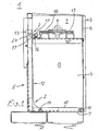
- FIGS 1 to 5 show a baler 1 with a new ejector 2.
- the baler 1 consists of a press housing 3, with a bottom surface 7, a rear wall 5, a front door 6-s. 6 to 9 with an integrated filling flap, not shown, and side walls 4, and surrounded by the press housing 3 shaft 34, arranged with at least one pressing region 8 and an overlying filling area 9, and one above the latter 9, here in the figures 1 to 2a, not shown, per se known drive for the baler, which is connected to a movable plate 34 in the press plate 15.
- the new ejector 2 consists of a lifting plate 10 which is rotatably mounted on the bottom surface 7 in the pressing region 8 of the shaft 34 by means of a bearing 11, a pull rod 12 with slider 12 a, which is preferably longitudinal - vertically - in the rear wall 5, with the lifting plate 10 is hingedly connected by a hinge 14 and in the upper end region has a specially angled, projecting into the pressing portion 8 end 24, and arranged from a arranged on the pressing plate entrainment of the temporary parts in the effective range of the end 24 of the drawbar 12 einschwenkbar are.
- a driver which consists of a pawl 16 and a driving hook 17 and is pivoted to a basic position so that a movement of the pressing plate 15 can take place; the catch hook 17 is formed in particular L-shaped.
- the pivoting of the driving hook 17 in the ejection position takes place when the front door 6 is open by the movement of a guided slide 18 via a handle element 19, while the slider 18 actuates the pawl 16.
- the pawl 16 and the catch hook 17 are mounted on a shaft 20 which is mounted in bearing blocks 21 and 22 which are mounted on the press plate 15.
- the slider 18 can manually through Operation of the handle member 19 in the direction of the rear wall 5 of the baler 1 are moved.
- the pawl 16 and the driving hook 17 are pivoted into a working position. If the pressure plate 15 now moves upward, the pull rod 12 is moved upwards via the driver hook 17, which engages in an angled end 24 of the pull rod 12, and the lifting plate 10 is pivoted upwards about the bearing 11 via the hinge 14.
- the material bale shown in part is ejected out of the pressing area 8 of the shaft 34 outwards in front of the baler by the front door 6, which is opened by approximately 180 degrees.
- the driving hook 17 strikes with its lower edge to the projecting into the pressing portion end 24 of the tie rod 12 and at the same time pivoted together with its pawl 16 in the said starting position automatically back ,
- the front door 6 is locked during the pressing operation by a closure device on one of the side walls of the press housing 3 while it is connected via hinges 6 with the other side wall.
- FIGS. 6 to 9 show details of the closure device, a latch 25 which is mounted on the press housing 3 and has a recess 26 in which a bolt 27 arranged on the front door 6 engages.
- a latch 25 which is mounted on the press housing 3 and has a recess 26 in which a bolt 27 arranged on the front door 6 engages.
- the bolt 27 By pivoting the bolt 25 upwards to a bearing 28 by means of movement of a handle 30, the bolt 27 snaps out of the recess 26 of the bolt 25 and the front door 6 can open according to Figure 7 by a defined angle range by the bolt 27th along a leading edge 29a of an opening beginning below the slot-like guide 29 moves until it abuts a guide 29 delimiting nose 31 of the bolt 25.
- the latch 25 has an outer projection 37 which abuts on further lifting of the bolt 25 in this phase of the opening operation to a above the locking pin 27 arranged securing pin 36 and an unintentional, fast opening - popping of the bolt 25 by the still pressurized front door 6 - prevented.
- the pressure plate 40 provided there is provided at its rear side, that is to say the rear wall 5 of the press housing 3, with at least one projecting U-shaped web 41. At the end, the two legs of the U-shaped web 41 are closed by a bolt 42, so that an enclosed gap 43 is formed, in which the binder for setting the finished pressed bale, usually band, is performed.
- the web 41 moves in a groove 5b provided in or on the rear wall 5, this groove 5b being formed by mutually spaced, angled limbs 5a 'of profile parts 5a of the rear wall 5.
- the inside width of this groove 5b is carried out as already described above.
- the feeding of the strip takes place in particular via a tube 33, the lower portion 33 a is directed so that the tape when inserted and pushed through the tube 33 is inevitably inserted into the gap 43 of the web 41.
- the tube 33 can be fastened either to the rear wall 5 of the press housing 3, or to the supporting structure of the drive unit, not shown above the filling area 9, or to the press plate 40 itself.
- the supply of the binder, not shown, to the tube 33 is carried out in a known manner, either from arranged on the back of the press housing or arranged in the front, upper region of the press supply rollers.
- the equipment of the baler with one or more control units together with safety circuits or devices, binder storage, binder tensioning device and the like units does not relate to the subject invention and were therefore not further described.
- This equipment of the baler is at the discretion of the operator or manufacturer of the baler.
Landscapes
- Engineering & Computer Science (AREA)
- Mechanical Engineering (AREA)
- Auxiliary Devices For And Details Of Packaging Control (AREA)
- Refuse Collection And Transfer (AREA)
- Basic Packing Technique (AREA)
- Preliminary Treatment Of Fibers (AREA)
- Press Drives And Press Lines (AREA)
- Separation By Low-Temperature Treatments (AREA)
Description
- Die Erfindung betrifft eine Ballenpresse gemäß dem Oberbegriff des Patentanspruches 1 zum Verdichten - Zusammenpressen - von insbesondere verbrauchten Verpackungsmaterialien bzw. Transport- und/oder Aufbewahrungsbehältern, wie Kartonagen, Folien, PET-Flaschen oder dergleichen Gegenstände und Materialien.
- Aus dem Stand der Technik sind eine Vielzahl von Abfallpressen unterschiedlichster Bauart zum Verdichten von verbrauchten Verpackungsmaterialien und besagten weiteren Gegenständen sowie eine Vielzahl von Verfahren und Vorrichtungen zum manuellen oder automatischen Abbinden von in diesen Abfallpressen gepressten Materialballen bekannt.
- So ist aus der
DE 197 38 060 A1 eine Abfallpresse - eine sogenannte Vertikal-Ballenpresse - mit einer Auswurfeinrichtung für die fertig gepressten Ballen bekannt, bei der im Bodenbereich des Pressschachtes der Abfallpresse eine schwenkbare Hubplatte und eine im wesentlichen in der Rückwand geführte, mit der Hubplatte gelenkig verbundene Zugstange vorgesehen sind. Die Zugstange ist zum Auswurf des fertigen Materialballens mittels eines Koppelteiles wahlweise mit der vertikal bewegbaren Pressplatte der Abfallpresse lösbar verbindbar, wobei das Koppelteil in abhängig von der Position der den Schacht der Presse verschließenden Frönttür, mechanisch zwangsgekoppelt ein- bzw. ausgeschaltet wird. - Zum Schließen des Pressschachtes wird die an einer Seitenwand des Schachtes der Presse drehbar gelagerte Fronttür an die Stirnkante (-fläche) der gegenüberliegenden Seitenwand angelegt und mittels eines Sicherheitsverschlusses an letzterer verriegelt. Solche Sicherheitsverschlüsse sind in verschiedenen Ausführungen bekannt, z.B. ein "Handrad-Stellspindel"-Verschluss aus der
DE 297 21 834 U1 oder aus derDE 195 45 766 A1 ein in seitliche Richtung schwenkbarer "Hebel"-Verschluss. - Eine Auswurfeinrichtung vorgenannter Bauart ist auch noch aus der
US-A-3 916 781 bekannt. - Bei einer Pressvorrichtung nach der
DE-A-2 630 906 umfasst die Auswurfeinrichtung für das gepresste Gut ebenfalls eine schwenkbare Hubplatte, die mit einer Zugstange verbunden ist, wobei letztere lösbar mit der Pressplatte verbindbar ist. Diese Zugstange befindet sich jedoch im Pressschacht der Presse. Das Betätigungselement für das Anlegen und Wegnehmen dieser Zugstange von der Pressplatte ragt durch die Rückwand des Pressschachtes nach außen und ist nur von der Rückseite der Presse aus zu betätigen. - Aus der
US-A-4 232 599 ist eine Ballenpresse bekannt, deren Auswurfeinrichtung eine im Bodenbereich schwenkbar gelagerte Hubplatte aufweist. Im entsprechenden Bereich ist in der Rückwand des Pressraumes eine Zugstange beweglich gelagert. Das eine Ende dieser Zugstange ist mit dem betreffenden Kantenbereich der Hubplatte verbunden. Das andere oben befindliche Ende dieser Zugstange ist hakenförmig ausgebildet und reicht in den Bewegungsraum der Pressplatte hinein. Damit es zu keiner Kollision kommt, ist die Pressplatte an ihrer Rückfront mit einer entsprechenden Aussparung versehen. Auf der Pressplatte dieser Presse ist ein Mitnehmer angeordnet. Er besteht aus einem Stab, der in seinen Endbereichen entsprechend abgewinkelt ist, so dass ein Betätigungsarm und ein Mitnahmearm entsteht. Für den Mitnehmer sind auf der Pressplatte Lagerstellen vorgesehen, so dass dessen Mitnahmearm von einer Arbeitsstellung in eine Ruhestellung und umgekehrt geschwenkt werden kann. In der Arbeitsstellung ist der Mitnahmearm in eine Position geschwenkt, so dass bei einer Aufwärtsbewegung der Pressplatte dieser Mitnahmearm unter den hakenförmigen Vorsprung der Zugstange greift und bei weiterer Aufwärtsbewegung der Pressplatte die Hubplatte anhebt, so dass der Ballen nach vorn aus der geöffneten Wand des Pressschachtes heraus bewegt wird. Nachteilig bei dieser Auswurfeinrichtung ist dass zum Lösen des Mitnahmearmes des Mitnehmers vorder Zugstange die Pressplatte in eine tief liegende Position bewegt werden muss. Aus Sicherheitsgründen ist eine Abwärtsbewegung der Pressplatte nur bei geschlossener Pressschachttür möglich Zum Ausschwenken des Mitnahmearmes aus der Arbeitsstellung in eine Ruhestellung muss also die den Pressschacht verschließende Tür wieder geöffnet werden. Um gefahrlos arbeiten zu können, muss für das Auswerfen des Ballens und Vorbereitung der Presse bezüglich dem Pressen jedes weiteren Ballens die Tür des Pressschachtes mehrmals geöffnet und geschlossen werden; bei dieser Gestaltung einer Auswurfeinrichtung ist der betreffende Abschnitt eines Arbeitszyklus für die Herstellung eines Ballens aus Abfallmaterial sehr zeitaufwändig. - Ausgehend von diesem Stand der Technik liegt der Erfindung die Aufgabe zugrunde, die Gesamtkonstrukion der Ballenpresse so zu verbessern, dass einerseits Erleichterungen für das Bedienungspersonal beim Öffnen der Fronttür - Ballenpressentür - bzw. der Pressschachttür und/oder beim Abbinden und Auswerfen des Materialballens geschaffen werden und anderseits die Sicherheit beim Öffnen und Schließen der Ballenpressentür erhöht wird, zudem soll der technische Aufwand für die Fertigung der Ballenpresse gering gehalten werden. Gelöst wird diese Aufgabe bei einer Ballenpresse nach dem Oberbegriff des Patentanspruchs 1 durch die im kennzeichnenden Teil des Patentanspruchs 1 angegebenen Mittel und Maßnahmen. Die nachgeordneten Unteransprüche 2 bis 6 beinhalten vorteilhafte Weiterbildungen und Ausführungsvarianten des Erfindungsgegenstandes.
- Die Erfindung geht dabei von einer Ballenpresse, insbesondere von einer Vertikal-Ballenpresse, zum Verdichten (Zusammenpressen) von insbesondere verbrauchten Verpackungsmaterialien bzw. Transport- und/oder Aufbewahrungsbehälter, wie Kartonagen, Folien, PET-Flaschen oder dergleichen Gegenstände und Materialien, aus, bei der die geschlossene Fronttür des Pressengehäuses mit einem "Hebel"-Verschluss verriegelt wird und/oder die im unteren Bereich des Schachtes der Presse, dem sogenannten Pressschacht eine Auswurfeinrichtung für den Ballen aufweist und/oder bei der wenigstens an und/oder in den zum Schacht gehörenden und/oder im Schacht geführten Teilen der Presse mindestens ein Mittel zur Führung des Bindematerials vorgesehen ist.
- Die Auswurfeinrichtung besitzt in der Regel eine auf oder in der Bodenfläche des von einem Pressengehäuse gebildeten Schachtes gelenkig gelagerte Hubplatte, und eine im wesentlichen in einer Rückwand des Pressengehäuses geführte, mit der Hubplatte ebenfalls gelenkig verbundene Zugstange, wobei die Zugstange mittels einer Mitnahmeeinrichtung wahlweise mit einer im besagten Schacht bewegbaren Pressplatte so verbindbar ist, dass bei Bedarf bei geöffneter Fronttür, die ansonsten wenigstens den Pressbereich des Schachtes verschließt, mittels der aufwärts bewegten Pressplatte die Auswurfeinrichtung betätigbar ist.
- Einerseits ist in neuartiger Gestaltung der Ballenpresse vorgesehen, dass die besagte Mitnahmeeinrichtung als schwenkbeweglicher, zeitweilig mit der Zugstange koppelbarer Mitnehmer ausgebildet ist, bestehend aus einer in Lagerböcken gelagerten Welle, an der eine Schaltklinke sowie ein Mitnehmerhaken derart angeordnet sind, dass insbesondere bei geschlossener Fronttür wenigstens der Mitnehmerhaken, bevorzugt auch die Schaltklinke, eine von der Rückwand weg zeigende, nach innen gerichtete Grundstellung und bei geöffneter Fronttür, zumindest zeitweilig für die Phase des Ballenauswurfes, eine zur Rückwand hin zeigende, nach außen gerichtete Auswurfstellung einnehmen.
- In dieser Auswurfstellung besteht während der Aufwärtsbewegung der Pressplatte zumindest zeitweilig eine Verbindung des Mitnehmerhakens mit der Zugstange der Auswurfeinrichtung.
- Vorteilhaft ist zudem die Positionierung der Lagerböcke des Mitnehmers mitsamt Welle, Schaltklinke nebst Mitnehmerhaken auf der Pressplatte sowie dass der Mitnehmerhaken durch die Schaltklinke betätigbar ist.
- Bevorzugt ist vorgesehen, dass der Mitnehmerhaken insbesondere als ein L-förmig ausgebildeter Haken vorgesehen ist.
- Weiterhin ist es vorteilhaft, dass bei geöffneter Fronttür mittels eines auf der Pressplatte geführten Schiebers, der manuell durch ein Griffelement oder automatisch betätigt wird, die Schaltklinke bewegbar ist.
- Ein bevorzugtes, vorteilhaftes Ausführungsbeispiel einer erfindungsgemäß gestalteten Ballenpresse, die alle der zuvor genannten drei Grundgedanken der Erfindung aufweist, ist schematisch in Zeichnungen vereinfacht dargestellt und wird im Folgenden näher beschrieben. Es zeigen:
- Fig. 1
- eine Seitenansicht in den aufgeschnittenen Schacht einer Ballenpresse, der Ballen aus Abfallmaterial ist fertig gepresst - jedoch nicht gezeigt -, die Pressplatte bewegt sich aufwärts;
- Fig. 2
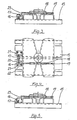
- eine Seitenansicht nach Fig. 1 , der Ballen wird ausgeworfen;
- Fig. 2a
- eine Seitenansicht nach Fig. 1, mit abwärts bewegter Pressplatte in zwei Momentpositionen;
- Fig. 3
- eine Seitenansicht einer Pressplatte mit schwenkbarem Mitnehmer in Grundstellung;
- Fig. 4
- eine Draufsicht auf Fig. 3;
- Fig. 5
- eine Seitenansicht einer Pressplatte mit schwenkbarem Mitnehmer in Auswurfstellung;
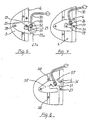
- Fig. 6 bis Fig. 9
- eine Verschlusseinrichtung für eine Tür des Schachtes, insbesondere des Pressschachtes, einer Ballenpresse in verschiedenen Arbeitsstellungen und
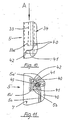
- Fig. 10 und Fig. 11
- neue Details einer Führung für die Bindemittel im Pressschacht einer Ballenpresse.
- Die Figuren 1 bis 5 zeigen eine Ballenpresse 1 mit einer neuen Auswurfeinrichtung 2. Die Ballenpresse 1 besteht dabei aus einem Pressengehäuse 3, mit einer Bodenfläche 7, einer Rückwand 5, einer Fronttür 6-s. Fig 6 bis 9 mit einer nicht näher dargestellten integrierten Einfüllklappe, sowie Seitenwänden 4, und einem vom Pressengehäuse 3 umgebenen Schacht 34, mit mindestens einem Pressbereich 8 und einem darüber befindlichen Einfüllbereich 9, sowie einem oberhalb von letzterem 9 angeordneten, hier in den Figuren 1 bis 2a nicht dargestellten, an sich bekannten Antrieb für die Ballenpresse, der mit einer im Schacht 34 bewegbaren Pressplatte 15 verbunden ist.
- Die neue Auswurfeinrichtung 2 besteht aus einer Hubplatte 10, die an der Bodenfläche 7 im Pressbereich 8 des Schachtes 34 mittels eines Lagers 11 drehbar gelagert ist, einer Zugstange 12 mit Gleitstück 12a, die bevorzugt längs - vertikal - in der Rückwand 5 geführt wird, mit der Hubplatte 10 durch ein Scharnier 14 gelenkig verbunden ist und im oberen Endbereich ein speziell abgewinkeltes, in den Pressbereich 8 hineinragendes Ende 24 aufweist, und aus einer an der Pressplatte angeordneten Mitnahmeeinrichtung, von der zeitweilig Teile in den Wirkbereich des Endes 24 der Zugstange 12 einschwenkbar sind.
- Dazu ist entsprechend Figur 3 an der Pressplatte 15 ein Mitnehmer vorgesehen, der aus einer Schaltklinke 16 und einem Mitnehmerhaken 17 besteht und in eine Grundstellung so geschwenkt ist, dass eine Bewegung der Pressplatte 15 erfolgen kann; der Mitnehmerhaken 17 ist insbesondere L-förmig ausgebildet.
- Das Schwenken des Mitnehmerhakens 17 in die Auswurfstellung erfolgt bei geöffneter Fronttür 6 durch die Bewegung eines geführten Schiebers 18 über ein Griffelement 19, dabei betätigt der Schieber 18 die Schaltklinke 16.
- Die Schaltklinke 16 und der Mitnehmerhaken 17 sind auf einer Welle 20 befestigt, die in Lagerböcken 21 und 22, die auf der Pressplatte 15 befestigt sind, gelagert ist.
- Bei geöffneter Fronttür 6 kann der Schieber 18 manuell durch Betätigung des Griffelementes 19 in Richtung der Rückwand 5 der Ballenpresse 1 bewegt werden. Mittels eines am Schieber 18 befestigten Schaltelementes 23 werden die Schaltklinke 16 und der Mitnehmerhaken 17 in eine Arbeitsstellung geschwenkt. Bewegt sich nun die Pressplatte 15 nach oben, wird über den Mitnehmerhaken 17, der in ein abgewinkeltes Ende 24 der Zugstange 12 eingreift, die Zugstange 12 nach oben bewegt und über das Scharnier 14 die Hubplatte 10 um das Lager 11 nach oben geschwenkt. Durch die Schräglage der Hubplatte 10 entsprechend Figur 2 wird der teils dargestellte Materialballen durch die hier um ca. 180 Grad geöffnete Fronttür 6 aus dem Pressbereich 8 des Schachtes 34 nach außen vor die Ballenpresse herausgeworfen.
- Während der aufwärst gerichteten Bewegung der Zugstange 12 gleitet ihr oberer Bereich mit samt dem Gleitstück 12a an der im wesentlichen in der Rückwand 5 angeordneten Führung 13 entlang und wird von dieser Führung 13 nach außen gezogen, so dass ihr Ende 24 von dem Mitnehmerhaken 17 herunter gezogen wird und die Zugstange 12 nebst der Hubplatte 10 wieder in die Ausgangsstellung fallen.
- Bei der nächsten Abwärtsbewegung der Pressplatte 15, in der Regel der nächste Presshub, schlägt der Mitnehmerhaken 17 mit seiner unteren Kante an das in den Pressbereich hinein ragende Ende 24 der Zugstange 12 an und wird zugleich nebst seiner Schaltklinke 16 in die besagte Ausgangsstellung automatisch zurück geschwenkt.
- Die Fronttür 6 wird während des Pressvorgangs durch eine Verschlusseinrichtung an einer der Seitenwände des Pressengehäuses 3 verriegelt während sie 6 über Scharniere mit der anderen Seitenwand verbunden ist.
- Die Figuren 6 bis 9 zeigen Details der Verschlusseinrichtung, einen am Pressengehäuse 3 gelagerten Riegel 25, der eine Ausnehmung 26 besitzt, in die ein an der Fronttür 6 angeordneter Bolzen 27 eingreift. Durch Schwenken des Riegels 25 nach oben, um ein Lager 28 mittels Bewegung eines Griffes 30, rastet der Bolzen 27 aus der Ausnehmung 26 des Riegels 25 aus und die Fronttür 6 kann sich entsprechend Figur 7 um einen definierten Winkelbereich öffnen, indem sich der Bolzen 27 entlang einer Führungskante 29a einer unterhalb der Ausnehmung beginnenden langlochartigen Führung 29 bewegt, bis er an einer die Führung 29 begrenzenden Nase 31 des Riegels 25 anschlägt. Oberhalb dieses Endbereiches der Führung 29 besitzt der Riegel 25 einen außen gelegenen Buckel 37, der bei weiterem Anheben des Riegels 25 in dieser Phase des Öffnungsvorganges an einen oberhalb vom Rastbolzen 27 angeordneten Sicherungszapfen 36 anschlägt und ein ungewolltes, überschnelles Öffnen - Aufspringen des Riegels 25 durch die noch unter Druck stehende Fronttür 6 - verhindert.
- Erst durch nochmaliges Anheben des Riegels 25 nach einer kurzen Verweilzeit, in der der gepresste, noch in dem Pressschacht befindliche Ballen entspannt und die Fronttür 6 im wesentlichen kraftmäßig entlastet wird, kann entsprechend Figur 8 der Rastbolzen 27 durch den nach unten zeigenden Ausgang 29b aus der Führung 29 gleiten und die Fronttür 6 vollständig geöffnet werden.
- Die dort vorgesehene Pressplatte 40 ist an ihrer Rückseite, also der Rückwand 5 des Pressengehäuses 3 zugewandt, mit mindestens einem vorspringenden u-förmigen Steg 41 ausgestattet. Endseitig werden die beiden Schenkel des u-förmigen Steges 41 durch einen Riegel 42 geschlossen, so dass ein umschlossener Spalt 43 entsteht, in welchem das Bindemittel zum Abbinden des fertiggepressten Ballens, in der Regel Band, geführt wird.
- Der Steg 41 bewegt sich in einer in oder an der Rückwand 5 vorgesehenen Nut 5b, wobei diese Nut 5b von zueinander beabstandeten, abgewinkelten Schenkeln 5a' von Profilteilen 5a der Rückwand 5 gebildet wird. Die lichte Weite dieser Nut 5b ist so wie bereits weiter vorn beschrieben ausgeführt. Diese in der Rückwand 5 des Schachtes der Presse vorgesehenen Nut 5b, die zur Aufnahme von Bereichen des Bindesmittels vorgesehen ist, damit das Bindemittel während des Pressvorganges nicht unnötig beansprucht wird, wird nunmehr durch den in diese Nut hinragenden Steg 41 freigehalten, so dass das Bindemittel nicht durch in die Nut 5b während des Pressvorganges eingequetschtes Abfallmaterial unnötig beeinflusst wird.
- Die Zuführung des Bandes erfolgt insbesondere über ein Rohr 33, dessen unterer Teilbereich 33a so gerichtet ist, dass das Band beim Ein- und Durchschieben durch das Rohr 33 zwangsläufig in den Spalt 43 des Steges 41 eingeführt wird. Das Rohr 33 kann dabei entweder an der Rückwand 5 des Pressengehäuses 3, oder an der nicht dargestellten, oberhalb des Einfüllbereiches 9 liegenden Tragkonstruktion der Antriebseinheit oder an der Pressplatte 40 selbst befestigt sein.
- Die Zuführung des nicht dargestellten Bindemittels zum Rohr 33 erfolgt in bekannter Art und Weise, entweder von an der Rückseite des Pressengehäuses angeordneten oder von im vorderen, oberen Bereich der Presse angeordneten Vorratsrollen.
- Die Ausstattung der Ballenpresse mit einer oder mehreren Steuereinheiten nebst Sicherheitsschaltungen bzw. -einrichtungen, Bindemittelbevorratung, Bindemittelspanneinrichtung und dergleichen Einheiten betrifft hier nicht den Erfindungsgegenstand und wurden daher nicht weiter beschrieben. Diese Ausstattung der Ballenpresse liegt im Ermessen des Betreibers oder Herstellers der Ballenpresse.
-
- 1
- Ballenpresse
- 2
- Auswurfeinrichtung
- 3
- Pressengehäuse
- 4
- Seitenwand
- 5
- Rückwand
- 5a
- Profilteil
- 5a'
- Schenkel
- 5b
- Nut
- 6
- Fronttür
- 7
- Bodenfläche
- 8
- Pressbereich
- 9
- Einfüllbereich
- 10
- Hubplatte
- 11
- Lager
- 12
- Zugstange mit .... 12a Gleitstück
- 13
- Führung
- 14
- Scharnier
- 15
- Pressplatte
- 16
- Schaltklinke
- 17
- Mitnehmerhaken
- 18
- Schieber
- 19
- Griffelement
- 20
- Welle
- 21
- Lagerbock
- 22
- Lagerbock
- 23
- Schaltelement
- 24
- abgewinkeltes Ende der Zugstange
- 25
- Riegel
- 26
- Ausnehmung
- 27
- Bolzen
- 28
- Lager
- 29
- Führung (langlochartig)
- 29a
- Führungskante
- 29b
- Ausgang
- 30
- Griff
- 31
- Nase
- 32
- Drehgelenk
- 33
- Rohr
- 33a
- unterer Teilbereich
- 34
- Schacht
- 35
- gemeinsame Gerade
- 36
- Sicherungszapfen
- 37
- Buckel
- 38
- Anschlagzapfen
- 40
- Pressplatte
- 41
- Steg (u-förmig)
- 42
- Riegel
- 43
- Spalt
Claims (6)
- Ballenpresse zum Verdichten - Zusammenpressen - von insbesondere verbrauchten Verpackungsmaterialien bzw. Transport- und/oder Aufbewahrungsbehältern, wie Kartonagen, Folien, PET-Flaschen oder dergleichen Gegenstände und Materialien, wenigstens umfassend :- ein Pressengehäuse (3), mit mindestens einer Fronttür (6) sowie mindestens einer Verschlusseinrichtung für letztere (6),- einen von dem Pressengehäuse (3) gebildeten Schacht (34), in welchem eine bewegbare Pressplatte (15; 40) vorgesehen ist,- eine dem Pressengehäuse (3) zugeordnete Auswurfeinrichtung (2) für die gepressten Ballen, bei der eine im wesentlichen in einer Rückwand (5) des Pressengehäuses (3) geführte und gelenkig mit einer bodenseitig (7) im Schacht (34) gelagerten Hubplatte (10) verbundene Zugstange (12) sowie eine Mitnahmeeinrichtung für eine zeitweilige Verbindung der Zugstange (12) mit der, vorzugsweise vertikal bewegbaren, Pressplatte (15; 40) vorgesehen sind, sowie eine Antriebseinheit, die zumindest mit der im Schacht (34) angeordneten Pressplatte (15; 40) verbunden ist,dadurch gekennzeichnet,
dass die Mitnahmeeinrichtung als schwenkbeweglicher, zeitweilig mit der Zugstange (12) koppelbarer Mitnehmer ausgebildet ist, bestehend aus einer in Lagerböcken (21,22) gelagerten Welle (20), an der eine Schaltklinke (16) sowie ein Mitnehmerhaken (17) derart angeordnet und
die Lagerböcke (21, 22) des Mitnehmers mitsamt Welle (20), Schaltklinke (16) sowie Mitnehmerhaken (17) so auf der Pressplatte (15; 40) positioniert sind, dass
insbesondere bei geschlossener Fronttür (6) wenigstens der Mitnehmerhaken (17), bevorzugt auch die Schaltklinke (16), eine von der Rückwand (5) weg zeigende, nach innen gerichtete Grundstellung und
bei geöffneter Fronttür (6), zumindest zeitweilig für die Phase des Ballenauswurfes, eine zur Rückwand (5) hin zeigende, nach außen gerichtete Auswurfstellung einnehmen,
wobei
in dieser Auswurfstellung während der Aufwärtsbewegung der Pressplatte (15; 40) zumindest zeitweilig eine Verbindung des Mitnehmerhakens (17) mit der Zugstange (12) besteht. - Ballenpresse nach Anspruch 1,
dadurch gekennzeichnet,
dass im oberen Bereich der Zugstange (12) ein außerhalb der Rückwand (5) befindliches Gleitstück (12a) fest an der Zugstange (12) angeordnet und zudem im Bewegungsbereich des Gleitstückes (12a) an bzw. in der Rückwand (5) eine Führung (13) vorgesehen ist, die (13) zumindest teilweise außen an der Rückwand (5) verläuft und eine, in aufsteigender Richtung gesehen, zunehmende Keilstärke aufweist, wobei die das Gleitstück (12a) kontaktierende Fläche - Kantebezüglich der Rückwand (5) zunehmend flieht. - Ballenpresse nach Anspruch 1 oder 2,
dadurch gekennzeichnet,
dass der Mitnehmerhaken (17) durch die Schaltklinke (16) betätigbar ist. - Ballenpresse nach einem der Ansprüche 1 bis 3,
dadurch gekennzeichnet,
dass der Mitnehmerhaken (17) insbesondere als ein L-förmig ausgebildeter Haken vorgesehen ist. - Ballenpresse nach einem der Ansprüche 1 bis 4,
dadurch gekennzeichnet,
dass auf der Pressplatte (15) ein geführter, vorzugsweise stabförmiger Schieber (18) angeordnet ist, mit einem Griffelement (19) an seinem einen und einem Schaltelement (23) an seinem anderen Ende, wobei bei Betätigung das Schaltelement (23) auf die Schaltklinke (16) einwirkt. - Ballenpresse nach einem der Ansprüche 1 bis 5,
dadurch gkennzeichnet,
dass der Schieber (18) automatisch betätigbar ist.
Priority Applications (1)
| Application Number | Priority Date | Filing Date | Title |
|---|---|---|---|
| EP07008174A EP1808288A3 (de) | 2000-06-26 | 2001-06-26 | Ballenpresse |
Applications Claiming Priority (2)
| Application Number | Priority Date | Filing Date | Title |
|---|---|---|---|
| DE10029979 | 2000-06-26 | ||
| DE10029979A DE10029979C2 (de) | 2000-06-26 | 2000-06-26 | Ballenpresse |
Related Child Applications (1)
| Application Number | Title | Priority Date | Filing Date |
|---|---|---|---|
| EP07008174A Division EP1808288A3 (de) | 2000-06-26 | 2001-06-26 | Ballenpresse |
Publications (3)
| Publication Number | Publication Date |
|---|---|
| EP1167005A2 EP1167005A2 (de) | 2002-01-02 |
| EP1167005A3 EP1167005A3 (de) | 2003-07-23 |
| EP1167005B1 true EP1167005B1 (de) | 2007-08-01 |
Family
ID=7646157
Family Applications (2)
| Application Number | Title | Priority Date | Filing Date |
|---|---|---|---|
| EP07008174A Withdrawn EP1808288A3 (de) | 2000-06-26 | 2001-06-26 | Ballenpresse |
| EP01115369A Expired - Lifetime EP1167005B1 (de) | 2000-06-26 | 2001-06-26 | Ballenpresse |
Family Applications Before (1)
| Application Number | Title | Priority Date | Filing Date |
|---|---|---|---|
| EP07008174A Withdrawn EP1808288A3 (de) | 2000-06-26 | 2001-06-26 | Ballenpresse |
Country Status (4)
| Country | Link |
|---|---|
| EP (2) | EP1808288A3 (de) |
| JP (1) | JP2002059296A (de) |
| AT (1) | ATE368565T1 (de) |
| DE (2) | DE10029979C2 (de) |
Family Cites Families (16)
| Publication number | Priority date | Publication date | Assignee | Title |
|---|---|---|---|---|
| DE1165451B (de) * | 1961-03-22 | 1964-03-12 | Wilmot Breeden Ltd | Hauben- oder Deckelverschluss insbesondere fuer Kraftfahrzeuge |
| US3916781A (en) * | 1973-02-16 | 1975-11-04 | American Environmental Prod | Bale ejection system |
| US3910181A (en) * | 1974-01-04 | 1975-10-07 | Fremco Manufacturing Inc | Baling press |
| DE2630906A1 (de) * | 1976-07-09 | 1978-01-12 | Schleicher Co Feinwerktech | Pressvorrichtung |
| US4232599A (en) * | 1978-10-19 | 1980-11-11 | J. V. Manufacturing & Welding, Inc. | Waste paper compacter with front access features |
| GB2060480B (en) * | 1979-10-18 | 1983-06-22 | Schleicher Co Feinwerktech | Baling press |
| DE3606309A1 (de) * | 1986-02-27 | 1987-09-03 | Hermann Schwelling | Fanghaken fuer den bedienungshebel des frontseitigen tuerverschlusses an horizontal wirkenden ballenpressen |
| DE3907334A1 (de) * | 1989-03-08 | 1990-09-20 | Schleicher Co Feinwerktech | Verschlussvorrichtung fuer die tuer einer ballenpresse |
| US5062358A (en) * | 1989-09-11 | 1991-11-05 | Marcella M. Fox | Bale ejector for a trash compactor |
| DE4215639C2 (de) * | 1992-03-07 | 1996-05-02 | Bermatingen Maschf | Vorrichtung zur Arretierung einer Auswurfklappe für den Preßkasten einer Ballenpresse |
| DE4336437A1 (de) * | 1993-10-26 | 1995-04-27 | Bermatingen Maschf | Ballenpresse |
| DE59505707D1 (de) * | 1994-12-27 | 1999-05-27 | Hermann Schwelling | Sicherheitsfronttür für Ballenpressen |
| US5575199A (en) * | 1995-03-22 | 1996-11-19 | Yamamoto; Soichiro | Compactor |
| DE19738060A1 (de) * | 1997-09-01 | 1999-03-11 | Hermann Schwelling | Abfallpresse mit Auswurfeinrichtung für Ballen |
| DE29721834U1 (de) * | 1997-12-10 | 1998-04-09 | Schwelling, Hermann, 88682 Salem | Sicherheitsverschluß für die Preßschachttür von Abfall-Ballenpressen |
| DE19817807B4 (de) * | 1998-04-21 | 2012-06-28 | Hermann Schwelling | Schachttür für eine Ballenpresse und zugehörige Ballenpresse |
-
2000
- 2000-06-26 DE DE10029979A patent/DE10029979C2/de not_active Expired - Fee Related
-
2001
- 2001-06-26 AT AT01115369T patent/ATE368565T1/de not_active IP Right Cessation
- 2001-06-26 DE DE50112780T patent/DE50112780D1/de not_active Expired - Fee Related
- 2001-06-26 EP EP07008174A patent/EP1808288A3/de not_active Withdrawn
- 2001-06-26 JP JP2001192758A patent/JP2002059296A/ja active Pending
- 2001-06-26 EP EP01115369A patent/EP1167005B1/de not_active Expired - Lifetime
Also Published As
| Publication number | Publication date |
|---|---|
| EP1167005A3 (de) | 2003-07-23 |
| EP1808288A3 (de) | 2008-01-23 |
| EP1808288A2 (de) | 2007-07-18 |
| ATE368565T1 (de) | 2007-08-15 |
| DE50112780D1 (de) | 2007-09-13 |
| JP2002059296A (ja) | 2002-02-26 |
| DE10029979A1 (de) | 2002-01-17 |
| DE10029979C2 (de) | 2003-11-06 |
| EP1167005A2 (de) | 2002-01-02 |
Similar Documents
| Publication | Publication Date | Title |
|---|---|---|
| DE2330157A1 (de) | Vorrichtung zum verdichten bzw. pressen von material wie abfall u.dgl | |
| DE69600765T2 (de) | Verfahren und vorrichtung zum formen von ballen aus losen materialien | |
| EP2283999B1 (de) | Ballenpresse | |
| DE2411744A1 (de) | Presse zum pressverbinden eines mindestens teilweise drahtfoermigen teiles mit einem abschlussteil | |
| DE10251516B4 (de) | Ballenpresse | |
| DE69505627T2 (de) | Drehbare Vorrichtung zum Freisetzen des Balles in Ballenpressen und Verfahren zum Verpressen zu Ballen | |
| EP1167005B1 (de) | Ballenpresse | |
| EP0899088B1 (de) | Abfallpresse mit Auswurfeinrichtung für Ballen | |
| EP3453529B1 (de) | Kasten-ballenpresse mit schiebetür sowie verfahren zum betreiben einer solchen kastenpresse | |
| DE29919933U1 (de) | Vorrichtung zum Zusammenpressen von Abfall | |
| DE19738060A1 (de) | Abfallpresse mit Auswurfeinrichtung für Ballen | |
| DE1274963B (de) | Muellfahrzeug | |
| DE1752244B2 (de) | Hydraulische Schrottschere mit einer den Schrott seitlich verdichtenden Sei tendruckpresse | |
| DE3412307A1 (de) | Ballenpresse zum zusammenpressen von materialien wie papierabfaellen o. dgl. zu ballen | |
| DE69404057T2 (de) | Verdichter | |
| EP1171283B1 (de) | Ballenpresse mit kippbarem presskasten sowie verfahren zur betätigung selbiger | |
| DE2917118C2 (de) | ||
| DE4114893A1 (de) | Holzspaltvorrichtung mit hydraulisch betaetigbarem stempel | |
| DE2254828A1 (de) | Vorrichtung zum verarbeiten von insbesondere in haushalten, restaurants und krankenhaeusern anfallenden abfaellen wie flaschen, glaeser, dosen, becher, kartons usw. zu muell | |
| DE20010786U1 (de) | Ballenpresse | |
| DE9004989U1 (de) | Ballenpresse | |
| DE10029440A1 (de) | Presse | |
| DE3238542A1 (de) | Vorrichtung zum fuehren und ziehen der abbindestreifen bei ballenpressen vertikaler bauart fuer abfallmaterialien | |
| DE4336437A1 (de) | Ballenpresse | |
| DE29904482U1 (de) | Schiebetür mit Klappe an einer Ballenpresse |
Legal Events
| Date | Code | Title | Description |
|---|---|---|---|
| PUAI | Public reference made under article 153(3) epc to a published international application that has entered the european phase |
Free format text: ORIGINAL CODE: 0009012 |
|
| AK | Designated contracting states |
Kind code of ref document: A2 Designated state(s): AT BE CH CY DE DK ES FI FR GB GR IE IT LI LU MC NL PT SE TR |
|
| AX | Request for extension of the european patent |
Free format text: AL;LT;LV;MK;RO;SI |
|
| PUAL | Search report despatched |
Free format text: ORIGINAL CODE: 0009013 |
|
| AK | Designated contracting states |
Designated state(s): AT BE CH CY DE DK ES FI FR GB GR IE IT LI LU MC NL PT SE TR |
|
| AX | Request for extension of the european patent |
Extension state: AL LT LV MK RO SI |
|
| 17P | Request for examination filed |
Effective date: 20040122 |
|
| AKX | Designation fees paid |
Designated state(s): AT DE ES FR GB SE |
|
| GRAP | Despatch of communication of intention to grant a patent |
Free format text: ORIGINAL CODE: EPIDOSNIGR1 |
|
| GRAS | Grant fee paid |
Free format text: ORIGINAL CODE: EPIDOSNIGR3 |
|
| GRAA | (expected) grant |
Free format text: ORIGINAL CODE: 0009210 |
|
| AK | Designated contracting states |
Kind code of ref document: B1 Designated state(s): AT DE ES FR GB SE |
|
| REG | Reference to a national code |
Ref country code: GB Ref legal event code: FG4D Free format text: NOT ENGLISH |
|
| REF | Corresponds to: |
Ref document number: 50112780 Country of ref document: DE Date of ref document: 20070913 Kind code of ref document: P |
|
| REG | Reference to a national code |
Ref country code: SE Ref legal event code: TRGR |
|
| ET | Fr: translation filed | ||
| PG25 | Lapsed in a contracting state [announced via postgrant information from national office to epo] |
Ref country code: ES Free format text: LAPSE BECAUSE OF FAILURE TO SUBMIT A TRANSLATION OF THE DESCRIPTION OR TO PAY THE FEE WITHIN THE PRESCRIBED TIME-LIMIT Effective date: 20071112 |
|
| GBV | Gb: ep patent (uk) treated as always having been void in accordance with gb section 77(7)/1977 [no translation filed] |
Effective date: 20070801 |
|
| PG25 | Lapsed in a contracting state [announced via postgrant information from national office to epo] |
Ref country code: GB Free format text: LAPSE BECAUSE OF FAILURE TO SUBMIT A TRANSLATION OF THE DESCRIPTION OR TO PAY THE FEE WITHIN THE PRESCRIBED TIME-LIMIT Effective date: 20070801 |
|
| PLBE | No opposition filed within time limit |
Free format text: ORIGINAL CODE: 0009261 |
|
| STAA | Information on the status of an ep patent application or granted ep patent |
Free format text: STATUS: NO OPPOSITION FILED WITHIN TIME LIMIT |
|
| 26N | No opposition filed |
Effective date: 20080506 |
|
| PG25 | Lapsed in a contracting state [announced via postgrant information from national office to epo] |
Ref country code: DE Free format text: LAPSE BECAUSE OF NON-PAYMENT OF DUE FEES Effective date: 20090101 |
|
| PG25 | Lapsed in a contracting state [announced via postgrant information from national office to epo] |
Ref country code: AT Free format text: LAPSE BECAUSE OF NON-PAYMENT OF DUE FEES Effective date: 20080626 |
|
| PGFP | Annual fee paid to national office [announced via postgrant information from national office to epo] |
Ref country code: FR Payment date: 20100716 Year of fee payment: 10 |
|
| REG | Reference to a national code |
Ref country code: FR Ref legal event code: ST Effective date: 20120229 |
|
| PG25 | Lapsed in a contracting state [announced via postgrant information from national office to epo] |
Ref country code: FR Free format text: LAPSE BECAUSE OF NON-PAYMENT OF DUE FEES Effective date: 20110630 |
|
| PGFP | Annual fee paid to national office [announced via postgrant information from national office to epo] |
Ref country code: SE Payment date: 20130624 Year of fee payment: 13 |
|
| PG25 | Lapsed in a contracting state [announced via postgrant information from national office to epo] |
Ref country code: SE Free format text: LAPSE BECAUSE OF NON-PAYMENT OF DUE FEES Effective date: 20140627 |
|
| REG | Reference to a national code |
Ref country code: SE Ref legal event code: EUG |