EP1160896A2 - Structure d'électrode, batterie et condensateur électrique à double couche et son procédé de fabrication - Google Patents
Structure d'électrode, batterie et condensateur électrique à double couche et son procédé de fabrication Download PDFInfo
- Publication number
- EP1160896A2 EP1160896A2 EP01113010A EP01113010A EP1160896A2 EP 1160896 A2 EP1160896 A2 EP 1160896A2 EP 01113010 A EP01113010 A EP 01113010A EP 01113010 A EP01113010 A EP 01113010A EP 1160896 A2 EP1160896 A2 EP 1160896A2
- Authority
- EP
- European Patent Office
- Prior art keywords
- electrode
- current
- collecting member
- solvent
- battery
- Prior art date
- Legal status (The legal status is an assumption and is not a legal conclusion. Google has not performed a legal analysis and makes no representation as to the accuracy of the status listed.)
- Withdrawn
Links
- 239000003990 capacitor Substances 0.000 title claims abstract description 15
- 238000004519 manufacturing process Methods 0.000 title claims abstract description 13
- 239000002904 solvent Substances 0.000 claims abstract description 41
- 239000000203 mixture Substances 0.000 claims abstract description 34
- 239000011230 binding agent Substances 0.000 claims abstract description 29
- 239000007772 electrode material Substances 0.000 claims abstract description 27
- 239000011248 coating agent Substances 0.000 claims abstract description 18
- 238000000576 coating method Methods 0.000 claims abstract description 18
- 150000001875 compounds Chemical class 0.000 claims abstract description 14
- 239000000463 material Substances 0.000 claims description 56
- 229920001940 conductive polymer Polymers 0.000 claims description 39
- 239000002322 conducting polymer Substances 0.000 claims description 31
- 238000000034 method Methods 0.000 claims description 21
- 239000004020 conductor Substances 0.000 claims description 20
- 239000000126 substance Substances 0.000 claims description 19
- 239000013543 active substance Substances 0.000 claims description 12
- 230000005611 electricity Effects 0.000 claims description 3
- 238000010438 heat treatment Methods 0.000 description 27
- SECXISVLQFMRJM-UHFFFAOYSA-N N-Methylpyrrolidone Chemical compound CN1CCCC1=O SECXISVLQFMRJM-UHFFFAOYSA-N 0.000 description 22
- 150000002500 ions Chemical class 0.000 description 16
- OKTJSMMVPCPJKN-UHFFFAOYSA-N Carbon Chemical compound [C] OKTJSMMVPCPJKN-UHFFFAOYSA-N 0.000 description 15
- 239000003792 electrolyte Substances 0.000 description 13
- 239000000523 sample Substances 0.000 description 12
- 229920000642 polymer Polymers 0.000 description 11
- 238000007599 discharging Methods 0.000 description 10
- 229910032387 LiCoO2 Inorganic materials 0.000 description 9
- 229910052799 carbon Inorganic materials 0.000 description 7
- 229910052744 lithium Inorganic materials 0.000 description 7
- 238000002156 mixing Methods 0.000 description 7
- 239000002245 particle Substances 0.000 description 7
- 239000000843 powder Substances 0.000 description 7
- 230000008569 process Effects 0.000 description 7
- ZWEHNKRNPOVVGH-UHFFFAOYSA-N 2-Butanone Chemical compound CCC(C)=O ZWEHNKRNPOVVGH-UHFFFAOYSA-N 0.000 description 6
- 239000006229 carbon black Substances 0.000 description 6
- 238000001035 drying Methods 0.000 description 6
- WHXSMMKQMYFTQS-UHFFFAOYSA-N Lithium Chemical compound [Li] WHXSMMKQMYFTQS-UHFFFAOYSA-N 0.000 description 5
- 239000002033 PVDF binder Substances 0.000 description 5
- 230000015556 catabolic process Effects 0.000 description 5
- 238000006731 degradation reaction Methods 0.000 description 5
- 229910002804 graphite Inorganic materials 0.000 description 5
- 239000010439 graphite Substances 0.000 description 5
- 239000002994 raw material Substances 0.000 description 5
- 229920000298 Cellophane Polymers 0.000 description 4
- 239000003575 carbonaceous material Substances 0.000 description 4
- 239000006185 dispersion Substances 0.000 description 4
- 229910003002 lithium salt Inorganic materials 0.000 description 4
- 159000000002 lithium salts Chemical class 0.000 description 4
- 229910052751 metal Inorganic materials 0.000 description 4
- 239000002184 metal Substances 0.000 description 4
- 239000011255 nonaqueous electrolyte Substances 0.000 description 4
- 229920002981 polyvinylidene fluoride Polymers 0.000 description 4
- 150000003839 salts Chemical class 0.000 description 4
- 239000007787 solid Substances 0.000 description 4
- 238000012360 testing method Methods 0.000 description 4
- RYGMFSIKBFXOCR-UHFFFAOYSA-N Copper Chemical compound [Cu] RYGMFSIKBFXOCR-UHFFFAOYSA-N 0.000 description 3
- LYCAIKOWRPUZTN-UHFFFAOYSA-N Ethylene glycol Chemical compound OCCO LYCAIKOWRPUZTN-UHFFFAOYSA-N 0.000 description 3
- HBBGRARXTFLTSG-UHFFFAOYSA-N Lithium ion Chemical compound [Li+] HBBGRARXTFLTSG-UHFFFAOYSA-N 0.000 description 3
- DNIAPMSPPWPWGF-UHFFFAOYSA-N Propylene glycol Chemical compound CC(O)CO DNIAPMSPPWPWGF-UHFFFAOYSA-N 0.000 description 3
- 238000007605 air drying Methods 0.000 description 3
- 229910052782 aluminium Inorganic materials 0.000 description 3
- XAGFODPZIPBFFR-UHFFFAOYSA-N aluminium Chemical compound [Al] XAGFODPZIPBFFR-UHFFFAOYSA-N 0.000 description 3
- 150000001786 chalcogen compounds Chemical class 0.000 description 3
- 239000010419 fine particle Substances 0.000 description 3
- 238000003780 insertion Methods 0.000 description 3
- 230000037431 insertion Effects 0.000 description 3
- 238000004898 kneading Methods 0.000 description 3
- 229910001416 lithium ion Inorganic materials 0.000 description 3
- 230000005012 migration Effects 0.000 description 3
- 238000013508 migration Methods 0.000 description 3
- 238000003825 pressing Methods 0.000 description 3
- 238000000926 separation method Methods 0.000 description 3
- 230000008016 vaporization Effects 0.000 description 3
- 229920000049 Carbon (fiber) Polymers 0.000 description 2
- PXHVJJICTQNCMI-UHFFFAOYSA-N Nickel Chemical compound [Ni] PXHVJJICTQNCMI-UHFFFAOYSA-N 0.000 description 2
- 239000004809 Teflon Substances 0.000 description 2
- 229920006362 Teflon® Polymers 0.000 description 2
- -1 V6O13 Chemical compound 0.000 description 2
- 239000011149 active material Substances 0.000 description 2
- 230000001154 acute effect Effects 0.000 description 2
- QVGXLLKOCUKJST-UHFFFAOYSA-N atomic oxygen Chemical compound [O] QVGXLLKOCUKJST-UHFFFAOYSA-N 0.000 description 2
- WERYXYBDKMZEQL-UHFFFAOYSA-N butane-1,4-diol Chemical compound OCCCCO WERYXYBDKMZEQL-UHFFFAOYSA-N 0.000 description 2
- 239000004917 carbon fiber Substances 0.000 description 2
- 238000007796 conventional method Methods 0.000 description 2
- 229910052802 copper Inorganic materials 0.000 description 2
- 239000010949 copper Substances 0.000 description 2
- 230000007423 decrease Effects 0.000 description 2
- GNTDGMZSJNCJKK-UHFFFAOYSA-N divanadium pentaoxide Chemical compound O=[V](=O)O[V](=O)=O GNTDGMZSJNCJKK-UHFFFAOYSA-N 0.000 description 2
- 230000000694 effects Effects 0.000 description 2
- 238000007602 hot air drying Methods 0.000 description 2
- 239000011244 liquid electrolyte Substances 0.000 description 2
- 229910052748 manganese Inorganic materials 0.000 description 2
- 239000011572 manganese Substances 0.000 description 2
- NUJOXMJBOLGQSY-UHFFFAOYSA-N manganese dioxide Chemical compound O=[Mn]=O NUJOXMJBOLGQSY-UHFFFAOYSA-N 0.000 description 2
- 229910052760 oxygen Inorganic materials 0.000 description 2
- 239000001301 oxygen Substances 0.000 description 2
- 239000002296 pyrolytic carbon Substances 0.000 description 2
- 230000005855 radiation Effects 0.000 description 2
- 239000007858 starting material Substances 0.000 description 2
- 238000007751 thermal spraying Methods 0.000 description 2
- WFKWXMTUELFFGS-UHFFFAOYSA-N tungsten Chemical compound [W] WFKWXMTUELFFGS-UHFFFAOYSA-N 0.000 description 2
- 229910052721 tungsten Inorganic materials 0.000 description 2
- 239000010937 tungsten Substances 0.000 description 2
- 238000009834 vaporization Methods 0.000 description 2
- WSGYTJNNHPZFKR-UHFFFAOYSA-N 3-hydroxypropanenitrile Chemical compound OCCC#N WSGYTJNNHPZFKR-UHFFFAOYSA-N 0.000 description 1
- 229920003026 Acene Polymers 0.000 description 1
- 229910017048 AsF6 Inorganic materials 0.000 description 1
- UJOBWOGCFQCDNV-UHFFFAOYSA-N Carbazole Natural products C1=CC=C2C3=CC=CC=C3NC2=C1 UJOBWOGCFQCDNV-UHFFFAOYSA-N 0.000 description 1
- UFHFLCQGNIYNRP-UHFFFAOYSA-N Hydrogen Chemical compound [H][H] UFHFLCQGNIYNRP-UHFFFAOYSA-N 0.000 description 1
- 229910000733 Li alloy Inorganic materials 0.000 description 1
- 229910002993 LiMnO2 Inorganic materials 0.000 description 1
- 229910003005 LiNiO2 Inorganic materials 0.000 description 1
- 229910001290 LiPF6 Inorganic materials 0.000 description 1
- 229910002097 Lithium manganese(III,IV) oxide Inorganic materials 0.000 description 1
- 229910014514 LixNiyM1-yO2 Inorganic materials 0.000 description 1
- 229910014512 LixNiyM1−yO2 Inorganic materials 0.000 description 1
- PWHULOQIROXLJO-UHFFFAOYSA-N Manganese Chemical compound [Mn] PWHULOQIROXLJO-UHFFFAOYSA-N 0.000 description 1
- CERQOIWHTDAKMF-UHFFFAOYSA-M Methacrylate Chemical compound CC(=C)C([O-])=O CERQOIWHTDAKMF-UHFFFAOYSA-M 0.000 description 1
- ISWSIDIOOBJBQZ-UHFFFAOYSA-N Phenol Chemical compound OC1=CC=CC=C1 ISWSIDIOOBJBQZ-UHFFFAOYSA-N 0.000 description 1
- 239000004372 Polyvinyl alcohol Substances 0.000 description 1
- NINIDFKCEFEMDL-UHFFFAOYSA-N Sulfur Chemical compound [S] NINIDFKCEFEMDL-UHFFFAOYSA-N 0.000 description 1
- 229910003092 TiS2 Inorganic materials 0.000 description 1
- OKKRPWIIYQTPQF-UHFFFAOYSA-N Trimethylolpropane trimethacrylate Chemical compound CC(=C)C(=O)OCC(CC)(COC(=O)C(C)=C)COC(=O)C(C)=C OKKRPWIIYQTPQF-UHFFFAOYSA-N 0.000 description 1
- 230000009471 action Effects 0.000 description 1
- 238000005054 agglomeration Methods 0.000 description 1
- 230000002776 aggregation Effects 0.000 description 1
- 229910045601 alloy Inorganic materials 0.000 description 1
- 239000000956 alloy Substances 0.000 description 1
- HSFWRNGVRCDJHI-UHFFFAOYSA-N alpha-acetylene Natural products C#C HSFWRNGVRCDJHI-UHFFFAOYSA-N 0.000 description 1
- 150000001450 anions Chemical class 0.000 description 1
- 238000007664 blowing Methods 0.000 description 1
- 239000007809 chemical reaction catalyst Substances 0.000 description 1
- 229910001914 chlorine tetroxide Inorganic materials 0.000 description 1
- 229910052804 chromium Inorganic materials 0.000 description 1
- 229910017052 cobalt Inorganic materials 0.000 description 1
- 239000010941 cobalt Substances 0.000 description 1
- GUTLYIVDDKVIGB-UHFFFAOYSA-N cobalt atom Chemical compound [Co] GUTLYIVDDKVIGB-UHFFFAOYSA-N 0.000 description 1
- 239000000571 coke Substances 0.000 description 1
- 239000002131 composite material Substances 0.000 description 1
- 239000011889 copper foil Substances 0.000 description 1
- 238000004132 cross linking Methods 0.000 description 1
- 238000000151 deposition Methods 0.000 description 1
- 239000011883 electrode binding agent Substances 0.000 description 1
- 238000005868 electrolysis reaction Methods 0.000 description 1
- 239000007849 furan resin Substances 0.000 description 1
- 239000007789 gas Substances 0.000 description 1
- 239000011521 glass Substances 0.000 description 1
- 238000000227 grinding Methods 0.000 description 1
- 229910052739 hydrogen Inorganic materials 0.000 description 1
- 239000001257 hydrogen Substances 0.000 description 1
- XLYOFNOQVPJJNP-UHFFFAOYSA-M hydroxide Chemical compound [OH-] XLYOFNOQVPJJNP-UHFFFAOYSA-M 0.000 description 1
- 229910052738 indium Inorganic materials 0.000 description 1
- APFVFJFRJDLVQX-UHFFFAOYSA-N indium atom Chemical compound [In] APFVFJFRJDLVQX-UHFFFAOYSA-N 0.000 description 1
- 239000001989 lithium alloy Substances 0.000 description 1
- 229910001496 lithium tetrafluoroborate Inorganic materials 0.000 description 1
- 229920002521 macromolecule Polymers 0.000 description 1
- 229910052960 marcasite Inorganic materials 0.000 description 1
- 238000005259 measurement Methods 0.000 description 1
- 238000012986 modification Methods 0.000 description 1
- 230000004048 modification Effects 0.000 description 1
- 229910052961 molybdenite Inorganic materials 0.000 description 1
- CWQXQMHSOZUFJS-UHFFFAOYSA-N molybdenum disulfide Chemical compound S=[Mo]=S CWQXQMHSOZUFJS-UHFFFAOYSA-N 0.000 description 1
- 229910052982 molybdenum disulfide Inorganic materials 0.000 description 1
- 239000004570 mortar (masonry) Substances 0.000 description 1
- 239000011331 needle coke Substances 0.000 description 1
- 229910052759 nickel Inorganic materials 0.000 description 1
- VLTRZXGMWDSKGL-UHFFFAOYSA-M perchlorate Chemical compound [O-]Cl(=O)(=O)=O VLTRZXGMWDSKGL-UHFFFAOYSA-M 0.000 description 1
- 230000002093 peripheral effect Effects 0.000 description 1
- 239000002006 petroleum coke Substances 0.000 description 1
- 239000005011 phenolic resin Substances 0.000 description 1
- 239000006253 pitch coke Substances 0.000 description 1
- 229920001197 polyacetylene Polymers 0.000 description 1
- 229920000767 polyaniline Polymers 0.000 description 1
- 229920001088 polycarbazole Polymers 0.000 description 1
- 230000000379 polymerizing effect Effects 0.000 description 1
- 229920000128 polypyrrole Polymers 0.000 description 1
- 229920000123 polythiophene Polymers 0.000 description 1
- 229920002451 polyvinyl alcohol Polymers 0.000 description 1
- 239000012254 powdered material Substances 0.000 description 1
- 238000002360 preparation method Methods 0.000 description 1
- NIFIFKQPDTWWGU-UHFFFAOYSA-N pyrite Chemical compound [Fe+2].[S-][S-] NIFIFKQPDTWWGU-UHFFFAOYSA-N 0.000 description 1
- 229910052683 pyrite Inorganic materials 0.000 description 1
- 229920005604 random copolymer Polymers 0.000 description 1
- 238000003756 stirring Methods 0.000 description 1
- 208000011117 substance-related disease Diseases 0.000 description 1
- 229910052717 sulfur Inorganic materials 0.000 description 1
- 239000011593 sulfur Substances 0.000 description 1
- 229910052719 titanium Inorganic materials 0.000 description 1
- 229910052723 transition metal Inorganic materials 0.000 description 1
- 150000003624 transition metals Chemical class 0.000 description 1
- 229910052720 vanadium Inorganic materials 0.000 description 1
Images


Classifications
-
- H—ELECTRICITY
- H01—ELECTRIC ELEMENTS
- H01M—PROCESSES OR MEANS, e.g. BATTERIES, FOR THE DIRECT CONVERSION OF CHEMICAL ENERGY INTO ELECTRICAL ENERGY
- H01M4/00—Electrodes
- H01M4/02—Electrodes composed of, or comprising, active material
- H01M4/04—Processes of manufacture in general
-
- H—ELECTRICITY
- H01—ELECTRIC ELEMENTS
- H01G—CAPACITORS; CAPACITORS, RECTIFIERS, DETECTORS, SWITCHING DEVICES, LIGHT-SENSITIVE OR TEMPERATURE-SENSITIVE DEVICES OF THE ELECTROLYTIC TYPE
- H01G11/00—Hybrid capacitors, i.e. capacitors having different positive and negative electrodes; Electric double-layer [EDL] capacitors; Processes for the manufacture thereof or of parts thereof
- H01G11/10—Multiple hybrid or EDL capacitors, e.g. arrays or modules
-
- H—ELECTRICITY
- H01—ELECTRIC ELEMENTS
- H01G—CAPACITORS; CAPACITORS, RECTIFIERS, DETECTORS, SWITCHING DEVICES, LIGHT-SENSITIVE OR TEMPERATURE-SENSITIVE DEVICES OF THE ELECTROLYTIC TYPE
- H01G11/00—Hybrid capacitors, i.e. capacitors having different positive and negative electrodes; Electric double-layer [EDL] capacitors; Processes for the manufacture thereof or of parts thereof
- H01G11/22—Electrodes
- H01G11/26—Electrodes characterised by their structure, e.g. multi-layered, porosity or surface features
- H01G11/28—Electrodes characterised by their structure, e.g. multi-layered, porosity or surface features arranged or disposed on a current collector; Layers or phases between electrodes and current collectors, e.g. adhesives
-
- H—ELECTRICITY
- H01—ELECTRIC ELEMENTS
- H01G—CAPACITORS; CAPACITORS, RECTIFIERS, DETECTORS, SWITCHING DEVICES, LIGHT-SENSITIVE OR TEMPERATURE-SENSITIVE DEVICES OF THE ELECTROLYTIC TYPE
- H01G11/00—Hybrid capacitors, i.e. capacitors having different positive and negative electrodes; Electric double-layer [EDL] capacitors; Processes for the manufacture thereof or of parts thereof
- H01G11/22—Electrodes
- H01G11/30—Electrodes characterised by their material
-
- H—ELECTRICITY
- H01—ELECTRIC ELEMENTS
- H01G—CAPACITORS; CAPACITORS, RECTIFIERS, DETECTORS, SWITCHING DEVICES, LIGHT-SENSITIVE OR TEMPERATURE-SENSITIVE DEVICES OF THE ELECTROLYTIC TYPE
- H01G11/00—Hybrid capacitors, i.e. capacitors having different positive and negative electrodes; Electric double-layer [EDL] capacitors; Processes for the manufacture thereof or of parts thereof
- H01G11/84—Processes for the manufacture of hybrid or EDL capacitors, or components thereof
- H01G11/86—Processes for the manufacture of hybrid or EDL capacitors, or components thereof specially adapted for electrodes
-
- H—ELECTRICITY
- H01—ELECTRIC ELEMENTS
- H01M—PROCESSES OR MEANS, e.g. BATTERIES, FOR THE DIRECT CONVERSION OF CHEMICAL ENERGY INTO ELECTRICAL ENERGY
- H01M4/00—Electrodes
- H01M4/02—Electrodes composed of, or comprising, active material
- H01M4/04—Processes of manufacture in general
- H01M4/0402—Methods of deposition of the material
- H01M4/0404—Methods of deposition of the material by coating on electrode collectors
-
- H—ELECTRICITY
- H01—ELECTRIC ELEMENTS
- H01M—PROCESSES OR MEANS, e.g. BATTERIES, FOR THE DIRECT CONVERSION OF CHEMICAL ENERGY INTO ELECTRICAL ENERGY
- H01M4/00—Electrodes
- H01M4/02—Electrodes composed of, or comprising, active material
- H01M4/04—Processes of manufacture in general
- H01M4/0402—Methods of deposition of the material
- H01M4/0409—Methods of deposition of the material by a doctor blade method, slip-casting or roller coating
-
- Y—GENERAL TAGGING OF NEW TECHNOLOGICAL DEVELOPMENTS; GENERAL TAGGING OF CROSS-SECTIONAL TECHNOLOGIES SPANNING OVER SEVERAL SECTIONS OF THE IPC; TECHNICAL SUBJECTS COVERED BY FORMER USPC CROSS-REFERENCE ART COLLECTIONS [XRACs] AND DIGESTS
- Y02—TECHNOLOGIES OR APPLICATIONS FOR MITIGATION OR ADAPTATION AGAINST CLIMATE CHANGE
- Y02E—REDUCTION OF GREENHOUSE GAS [GHG] EMISSIONS, RELATED TO ENERGY GENERATION, TRANSMISSION OR DISTRIBUTION
- Y02E60/00—Enabling technologies; Technologies with a potential or indirect contribution to GHG emissions mitigation
- Y02E60/10—Energy storage using batteries
-
- Y—GENERAL TAGGING OF NEW TECHNOLOGICAL DEVELOPMENTS; GENERAL TAGGING OF CROSS-SECTIONAL TECHNOLOGIES SPANNING OVER SEVERAL SECTIONS OF THE IPC; TECHNICAL SUBJECTS COVERED BY FORMER USPC CROSS-REFERENCE ART COLLECTIONS [XRACs] AND DIGESTS
- Y02—TECHNOLOGIES OR APPLICATIONS FOR MITIGATION OR ADAPTATION AGAINST CLIMATE CHANGE
- Y02E—REDUCTION OF GREENHOUSE GAS [GHG] EMISSIONS, RELATED TO ENERGY GENERATION, TRANSMISSION OR DISTRIBUTION
- Y02E60/00—Enabling technologies; Technologies with a potential or indirect contribution to GHG emissions mitigation
- Y02E60/13—Energy storage using capacitors
-
- Y—GENERAL TAGGING OF NEW TECHNOLOGICAL DEVELOPMENTS; GENERAL TAGGING OF CROSS-SECTIONAL TECHNOLOGIES SPANNING OVER SEVERAL SECTIONS OF THE IPC; TECHNICAL SUBJECTS COVERED BY FORMER USPC CROSS-REFERENCE ART COLLECTIONS [XRACs] AND DIGESTS
- Y10—TECHNICAL SUBJECTS COVERED BY FORMER USPC
- Y10T—TECHNICAL SUBJECTS COVERED BY FORMER US CLASSIFICATION
- Y10T29/00—Metal working
- Y10T29/49—Method of mechanical manufacture
- Y10T29/49002—Electrical device making
- Y10T29/49108—Electric battery cell making
- Y10T29/49115—Electric battery cell making including coating or impregnating
Definitions
- the present invention relates to a novel method of manufacturing an electrode structure, and to a manufacturing method for producing a battery and an electrical double-layer capacitor utilizing the electrode structure.
- a typical electrode structure of the prior art is manufactured by coating a current-collecting member surface with a compound mixture containing an electrode material, a powdered electrically-conducting substance, binder and solvent, vaporizing the solvent by directing hot air flow, and drying the coating to attach an electrode film to the surface of the current-collecting member.
- the electrode film is prone to peel away from the current-collecting member and as a consequence the electrical resistance of the electrode film does not decrease.
- hot air flow is generated by a hot air heater utilizing outside air of 80-200 °C at 15-25 m/second.
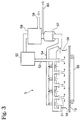
- the hot air heater is configured such that electrode structures containing an electrode film h coated on a current-collecting member g is moved by the conveyor d into the cabinet c and hot air flow f is directed onto the electrode film h from a hot air outlet to vaporize the solvent involved.
- the hot air flow moves the solvent outwards by way of the cabinet outlet e.
- An object of this invention is to provide an electrode film that adheres well to the current-collecting member.
- Another object of this invention is to provide an electrode film with low electrical resistance.
- Another object of this invention is to provide a battery or double-layer capacitor with an electrode film having low electrical resistance and good bonding.
- This invention relates to a method of manufacturing an electrode structure by coating a compound mixture comprising an electrode material, binder, and solvent onto a current-collecting member, directing warm breeze onto the compound mixture coating to vaporize the solvent and form an electrode film on the current-collecting member.
- the electrode structure of this invention can be used in the electrodes of electronic components wherein typically an electrolyte is provided between the electrodes.
- the electrical component is a battery
- the electrode structure exchanges electricity by way of electrolyte ions.
- the electrical component is a double-layer capacitor
- the electrode structure forms an electrical double-layer between a material with a large surface area and electrolyte.
- FIG. 1(A) illustrates examples of typical electrode structures.
- the electrode structure of FIG. 1(A) is used as the positive electrode of a battery.
- the electrode structure 1 is an electrode film 18 consisting of an electrode active material as an electrode material 11, an electrically-conductive material 14, and binder 17, attached to the surface of the current-collecting member 13.
- LiCoO 2 i.e., the powdered electrode active substance, for example, is used as the electrode active material.
- FIG. 1(B) an ion-conducting polymer 12 is attached to the powered electrode material 11 of FIG. 1(A).
- the ion-conducting polymer 12 also acts as a binder.
- FIG. 1(C) shows an electrode structure used in the negative electrode of a battery.
- the electrode structure 1 is an electrode film 18 consisting of a powdered electrode active substance as an electrode material 11 and a binder 17, attached to the surface of the current-collecting member 13.
- graphite powder is, for example, used as the powdered electrode active substance.
- FIG. 1(D) is the electrode material of FIG. 1(C) coated with the ion-conducting polymer 12. This ion-conducting polymer also functions as a binder.
- the electrode structure is used as an electrode for the double-layer capacitor.
- the electrode structure 1 is an electrode film 18 consisting of a large surface area material as an electrode material 11 and a binder 17, attached to the surface of the current-collecting member 13.
- active carbon material i.e., powdery high surface area material
- large surface area material i.e., powdery high surface area material
- an ion-conducting polymer 12 is attached to the powdery high surface area material of FIG. 1(E). This ion-conducting polymer also functions as a binder. When the electrode material 11 is covered with the ion-conducting polymer 12, this ion-conducting polymer functions as a binder. The electrode material covered with the ion-conducting polymer is described in detail later on.
- FIG. 2 An example of the manufacturing method of this invention to produce an electrode structure is shown in FIG. 2.
- the electrode material 11, electrically-conductive material 14, binder 17, and solvent 19 are mixed together by slurrying in a mixer 3 to obtain the mixed material 31.
- the mixed material 31 is lightly coated onto the surface of the current-collecting member 13.
- the method for coating the mixed material 31 may proceeded by a doctor knife applicator.
- the solvent of the mixed material coating is vaporized by brez/air heating, and the material coating dried and attached to the current-collecting member 13 as the electrode film 18.
- this invention provides the same advantages as an electrode film obtained through the method of drying the mixed material coating by infrared radiation as disclosed in Japanese Patent Application No. 2000-32279 by the present inventors.
- Brez/Air heating is a heating method for drying the mixed material 31 and is conducted by directing brez/air with heat, i.e., warm breeze 51, to the mixed material 31.
- a brez/air heater 51 is a device used to heat an object by blowing air, wherein the brez/air with heat, i.e., the warm breeze 51, is directed onto the mixed material to dry the mixed material into electrode film 18.
- the brez/air is injected from an outside air inlet 59, dried by a dry air generator 58, and heated by an air heater 52, and the warm breeze 51 is injected into the cabinet 56 via a guide tube 53.
- the electrode film 18 coated on the current-collecting member 13 is moved within the cabinet 56 by a conveying means such as a conveyer 55.
- the warm breeze 51 is directed onto the electrode film 18, vaporizes the solvent involved in the electrode film 18, and is subsequently directed into the solvent collector 57 via ducts 54, thereby collecting the vaporized solvent.
- the warm breeze 51 after removing the solvent is exhausted from partial ducts 60, and the rest of the air is returned into the dry air generator 58.
- the warm breeze 51 in this invention preferably is a gas flow such as an air flow of 60-150 °C at 0.1-3m/second or lower.
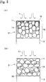
- FIG. 4 shows an enhanced view of the internal state of the mixed material 31 when the solvent 19 of the mixed material coated on the current-collecting member 13 is vaporized.
- FIG. 4(A) shows the conventional method of applying hot air flow f of 80-200 °C at 15-25 m/second onto the mixed material 31 to vaporize the solvent 32 mixed with a binder.
- FIG. 4(B) shows the method of this invention wherein the warm breeze 51 of 60-150 °C at 1-3m/second, is directed onto the mixed material 31 to vaporize the solvent 32 mixed with a binder.
- the solvent vaporization process works as follows in the case of the conventional method of directing the hot air flow f of FIG. 4(A). First, when hot air flow f is applied to the surface of the mixed material, the area around the surface of the mixed material 31 suddenly warms up in the hot air flow f, and the solvent on the surface is vaporized and blown away by the hot air flow f.
- the solvent near the surface therefore quickly vaporizes, and to compensate, the solvent at the interior of the mixed material and near the collector electrode moves to the vicinity of the surface
- the binder contained in the solvent and the powdered conducting material are at this time carried to the surface of the mixed material 31 along with the solvent. That is, migration of the binder and the powdered conducting material occurs.
- the binder concentration of the mixed material in the vicinity of the current-collecting member 13 and the powdered conducting material concentration become thin.
- the electrode film therefore tends to easily peel away from the current-collecting member 13; the relative electrical resistance in the vicinity of the current-collecting member becomes high; and the resistance of the electrode overall becomes high.
- the solvent vaporization process works as follows.
- the warm breeze 51 When the warm breeze 51 is directed onto the mixed material surface, the warm breeze 51 gradually heats up the entire mixed material and gradually vaporizes the solvent from the mixed material surface.
- the concentrations of binder and powdered conducting material 14 therefore remain uniform overall. That is, migration of the binder and the powdered conducting material is prevented.
- the binder concentration in the vicinity of the current-collecting member 13 does not become weak (or thin) in the electrode material of dried mixed material 31. Accordingly, the electrode film adheres well to the current-collecting member 13. Further, the concentration of the powdered conducting material in the vicinity of the current-collecting member 13 does not become weak either, so that the electrical resistance of the overall electrode film is low.
- the current-collecting member 13 may be any material capable of conducting electricity, and the material and shape can be selected according to the electronic component containing member 13.
- the electrically-conductive material may be aluminum or copper and formed into a plate, leaf or mesh shape. When the current-collecting member is a plate or leaf shape, one or both sides are used according to the structure of the electronic component.
- the electrode film 18 for adhering to the current-collecting member 13 may be pressed into the current-collecting member to make it further adhere.
- a fixing device 4 as shown in Fig. 10 is used.
- An electrode structure 1 made from current-collecting member coated with mixed material is enclosed by the pressure rollers 41.
- Electrode film can be bonded to the current-collecting member by applying a rotating pressure with the pressure device 43 and by means of the backroller 42 applied against pressure rollers 41.
- the fixing or adhesion device 4 is not limited to a four-roller device and is sufficient as long as it presses and adheres the electrode film to the current-collecting member .
- a two-roller press device may be appropriate.
- FIG. 1(A) or FIG. 1(B) can be used as the positive electrode while an electrode structure useful as a negative electrode is shown in FIG. 1(C) or FIG. 1(D).
- An electrolyte may be positioned between the respective electrode structures.
- FIG. 5 shows an example in which a battery comprises an electrode structure of FIG. 1(B) as the positive electrode and an electrode structure of FIG. 1(D) as the negative electrode.
- FIG. 5(A) shows the case when the electrolyte is a liquid electrolyte 16, and a separator 15 is placed between the electrodes.
- FIG. 5(B) shows the case when the electrolyte is an ion-conducting polymer 12 in solid.
- the separator 15 is installed to isolate one pair of electrode structures 1, and the electrolyte can be used in solid when required according to circumstances.
- the double-layer capacitor has a structure with electrolyte placed between one pair of electrodes of the electrode structure of FIG. 1(E) or one pair of electrodes of the electrode structure of FIG. 1(F).
- a double-layer capacitor utilizing the electrode structure of FIG. 1(E) is shown in FIG. 6(A)
- a double-layer capacitor utilizing the electrode structure of FIG. 1(F) is shown in FIG. 6(B).
- FIG. 6(A) shows the case when the electrolyte is a liquid electrolyte 16, and a separator 15 is placed between the electrodes.
- FIG. 6(B) shows the case when the electrolyte is an ion-conducting polymer 12 in solid.
- the separator 15 is installed to isolate one pair of electrode structures 1, and the electrolyte can be used in solid when required according to circumstances.
- Electrode structure sample pieces 1 - 8 were dried using two types of heating methods; one method was the hot air flow method of the prior art and the other was breezing/air heating method of this invention. The peeling strength and impedance ( ⁇ /ohm) of these sample pieces were measured. A battery using the electrode structures was prepared and a cycle degradation was measured. The ratio (proportions) of electrode material, conductive material, binder, and solvent material used in the preparation of the sample pieces are shown in Table 1.
- Samples 1 through 6 represent electrodes useful for capacitors.
- the electrode material was made from phenol active carbon (made by Kansai Chemical Corp.) which was dry mixed with carbon black, i.e., the powdered conductive material, as the conductive material, utilizing a mixer.
- Samples 7 through 8 represent positive electrodes for batteries. Carbon black of the powdered conductive material as the electrode was added to LiCoO 2 of the powdered electrode active substance which served as the electrically-conductive material by dry type mixing performed utilizing a mixer. The binder was then added to all the samples 1 through 8 and mixing performed. A specified amount of solvent was further added and mixing was performed. After mixing, the material was coated onto the collector element with a doctor knife applicator. The samples were then dried by brez/air heating or conventional hot air heating.
- the samples 1 to 6 utilized active carbon material as the electrode material.
- Sample 7 utilized LiCoO 2 as the electrode material and PVDF (polyvinylidene fluoride) as the binder.
- Sample 8 utilized LiCoO 2 as the electrode material and polymer A2 as the binder, and was covered with ion-conducting polymer.
- Samples 1 through 4 contained no carbon black powdered electrically-conducting substance, and samples 5 through 11 contained carbon black though there were differences in the concentrations used in the samples.
- Polymer A1, polymer A2, Teflon powder, and PVDF were used as the binders.
- Polymer A1 and polymer A2 were ion-conducting polymers. The raw materials used to form polymers A1 and A2 are shown in Table 2 and Table 3, respectively.
- the air heater 52, the ancillary dry air generator 58, and the solvent collector 57 are driven to generate dry air.
- the warm breeze is supplied into the cabinet 56 at 1 m/second (approximately minimum of 0.5-maximum 1.5 m/second)
- An area within the cabinet 56 wherein the warm breeze is flown through is divided into a first zone keeping the warm breeze approximately at 80 °C and a second zone keeping the warm breeze approximately at 100 °C.
- the sample material is supplied into the first zone then into the second zone at 3 m/minute.
- Length of the first and second zones each is approximately 4.5 m (total of 9 m), the time required for the air to flow though is approximately 3 minutes, and the mixed material is dried for 3 minutes. As such, the mixed material was dried so that migration of the binder and the powdered conducting material may be prevented.
- a device as shown in FIG. 11 was utilized for the hot air heating, where outside air within a room is drawn from outside of the device.
- the hot air flow had a 60 % relative humidity and was directed at the sample at 15m/second for 3 minutes to dry the mixed material.
- the same procedure as in brez/air heating was performed except for the wind velocity and drying of the hot air flow.
- the hot air flow of dried outside air as in this invention was also tested. That is, all the same steps in the above hot air flow heating are used except for the dry air instead of outside air (having 60 % relative humidity).
- cellophane tape (KOKUYO TSS18N width 18 mm, thickness 50 ⁇ m) was attached to the electrode film fabricated on the surface of the current-collecting member, and the cellophane tape was then pulled away to make the electrode film stuck onto the cellophane tape separate from the current-collecting member.
- a peeling strength ranking could then be established according to the tape separate from the current-collecting member.
- a peeling strength ranking could then be established according to the amount of electrode film peeled from the surface of the current-collecting member.
- FIG. 7 taken from photographs shows the electrode film stuck to the cellophane tape.
- FIG. 7(A) taken from photographs shows a small flaked portion of the upper electrode film, which is ranked a. (The blacken portion in the photograph is the flaked portion of the electrode film.)
- FIG. 7(B) taken from photographs shows a small flaked portion of the middle electrode film, which is ranked b. (The blacken portion in the photograph is the flaked portion of the electrode film.)
- FIG. 7(C) taken from photographs shows an electrode film completely peeled from the current-collecting member, which is ranked c. (The blacken portion in the photograph is the flaked portion of the electrode film.) For samples measurement, the results of peeling strength and impedance ( ⁇ /ohm) are shown in Table 4.
- the electrodes formed on the collector element were enclosed by copper plates of 2 centimeters in diameter and 5 millimeters thick. A pressure of 4.5 kilograms per centimeter was applied from above and below, and the resistance at 10 kilohertz AC was measured with an impedance analyzer.
- An electrode prepared according to the above-embodiment was used to prepare a battery, and Table 5 shows comparison results of dry brez/air heating, outside hot air heating, and dry hot air heating.
- a lithium ion battery was prepared by combining the positive electrode using LiCoO 2 obtained through brez/air heating and hot air heating (including outside air and dry air) of sample 7 as an active material and a negative electrode using graphite as an active material, which was used as test samples. Charging and discharging were performed using the test samples.
- the electrode thus obtained had a thickness of 80 ⁇ m.
- the battery had a separator between the positive electrode having an electrode film of 0.94 cm 2 on one surface and the negative electrode having an electrode film of 0.94 cm 2 on one surface in order to prepare a coincell. Electrolyte was filled up to prepare a test cell. EC/DEC(1/1)V/V solution dissolving 1.0 M of LiPF 6 was used as electrolyte.
- electrode materials within the electrode When air with relatively higher humidity is heated to prepare an electrode, electrode materials within the electrode sometime absorb moisture. Especially for a battery and an electrical double-layer capacitor used with high voltage (i.e., 1.5 V or more), a trace of moisture absorbed may cause electrolysis within the electrode to generate hydrogen and oxygen. As a result of the above
- LIPF 6 and LiBF 4 may be used as the ion conductive salt. Since these materials react with a trace of moisture and generate HF, HF generated corrodes a wide variety of materials to cause cycle degradation. Accordingly, zero temperature of air as dry air should be -10 °C or lower, preferably -20 °C or lower, more preferably -40 °C or lower and most preferably -50 °C or lower.
- the condition for charging should be such that charging is first conducted at a charging current of 0.21-0.26 mA/cm 2 , secondly, maintaining a charging voltage of 4.2 V for two hours upon reaching 4.2 V, and thirdly, pausing the charging for ten minutes.
- the condition for discharging should be such that discharging is conducted at a discharging current of 0.21-0.26 mA/cm 2 up to 2.7 V of final voltage and pausing the discharging for ten minutes. Charging and discharging are repeated under room temperature.
- the electrode material coated with ion-conducting polymer is described next.
- the powdered electrode active substance 11 has the shape of particles consisting of bonded particles like LiCoO 2 .
- the process for depositing the ion-conducting polymer 12 is also shown.
- “adhere” or “adhesion” means that ions are attached in such manner that the ions can migrate between the ion conductive polymer 12 and the entire surface of the powdery electrode material. It means that the ion conductive polymer 12 adheres to the surface of the powdery electrode material 11 and covers it with the ion conductive polymer 12.
- the activity is suppressed and can be turned a to more stable state.
- the deposit of ion-conducting polymer 12 is thick, the electrical conduction decreases, and the current (charge) collection is poor.
- the powder shape such as for the powdered electrode active substance 11 and powdered conducting material 14 is a fine particle substance. Further, such a powder is a collection of many substances. In certain cases, this fine particle substance refers to a state wherein a large number of substances in a fine particle state constitute an agglomeration.
- the powdered electrode active substance uses ion insertable-separable materials and ⁇ -conjugated conductive macromolecular materials.
- the electrode active substance used as the positive electrode for non-aqueous electrolyte batteries there are no particular restrictions on the electrode active substance used as the positive electrode for non-aqueous electrolyte batteries.
- chalcogen compounds allowing ion insertion/separation or composite chalcogen compounds containing lithium are recommended.
- the chalcogen compound having lithium as described above includes LiCoO 2 , LixNiyM 1 -yO 2 (where M represents at least one type of metal element selected from transition metal or aluminum, or more preferably, it represents at least one type of metal element selected from Co, Mn, Ti, Cr, V, or Al, and 0.05 ⁇ x ⁇ 1.10 and 0.5 ⁇ y ⁇ 1.0), LiNiO 2 , LiMnO 2 , LiMn 2 O 4 , etc.
- oxide, salt or hydroxide of lithium, cobalt, nickel or manganese as starting materials, these starting materials are mixed in adequate composition, and the mixture is fired in the temperature range of 600 °C - 1000 °C under oxygen atmosphere.
- the electrode active substance used as the negative electrode for non-aqueous electrolyte batteries there are no particular restrictions on the electrode active substance used as the negative electrode for non-aqueous electrolyte batteries. However, a material allowing lithium ion insertion/separation may be used, and lithium metal, lithium alloys (alloys such as lithium and aluminum, lead, indium) and carbon quality materials may be utilized.
- Polyacetylene types polyaniline types, polypyrrole types, polythiophene types, poly- ⁇ (para)-phenylene types, polycarbazole types, polyacene types and sulfur polymer types are among the useful ⁇ -conjugated conductive macromolecular materials.
- lithium metals in the negative electrode achieves a large battery capacity particularly in primary non-aqueous electrolyte batteries.
- carbon materials in the negative electrodes that are capable of lithium ion insertion/separation yields a longer battery cycle life span.
- carbon material used but materials such as pyrolytic carbon types, coke types (pitch coke, needle coke and petroleum coke, etc.) graphite types, glass carbon types, organic macromolecular compound fired products (carbonized pieces baked to a suitable temperature such as phenol resin and furan resin) carbon fibers and active carbon may be utilized.
- the powdered electrically-conducting substance raises the conductivity of the electrode structure and though there are no particular restrictions, materials such as metal powder and carbon powder may be used.
- materials such as metal powder and carbon powder may be used.
- preferred carbon powders are pyrolytic carbons such as carbon black, and their graphite products, artificial and natural scaly graphite powder, carbon fibers and their graphite products, etc. Product mixtures of these carbon powders are also utilized.
- the ion conductive polymer is a polymer, which can dissolve at least an ion conductive salt such as lithium salt at concentration of 0.1 M (mol/l) or more shows an electrical conductivity of 10 -8 S (Siemens)/cm or more at room temperature.
- it is an ion conductive polymer, which dissolves at least ion conductive salt such as lithium salt and exhibits electrical conductivity of 10 -2 S/cm - 10 -5 S/cm at room temperature.
- the lithium salt is at least one type of lithium salt having ClO 4 - , CF 3 SO 3 - , BF 4 - , PF 6 - , AsF 6 - , SbF 6 - , CF 3 CO 2 - or (CF 3 SO 2 ) 2 N - as anion.
- the ion-conducting polymer raw material is a substance which produces the ion-conducting polymer by polymerizing, crosslinking, etc., when energy is supplied externally.
- the raw material itself may be a polymer.
- the energy may be heat, ultraviolet light, light or electron radiation.
- the method of coating the powdered conductive material with the ion-conducting polymer as is shown in Fig. 8 is to press-slide the ion-conducting polymer and the powdered electrode active substance against each other.
- the particle surfaces of the powdered electrode active substance are coated with the ion-conducting polymer, no voids are formed, and gaps in the powdered substance are reduced.
- Press-sliding is the action of sliding while pressing mixtures 10 of the ion-conducting polymer 12 or the raw material of the ion-conducting polymer 12 and the powdered substance 11 together. An external force is applied to the mixtures so that they cohere to each other and the particles rotate, and this process is performed repeatedly to obtain a press-sliding product.
- the press-sliding and kneading mixer is shown, for example, in Fig. 9(A).
- the mixture 10 of the ion conductive polymer 12 and the powdered material 11, or a mixture containing this mixture and a mixture 10 containing solvent, is placed in a container 21, and a main blade 22 is rotated. There is a gap between a bottom 211 of the container 21 and the main blade 22.
- a part of the mixture 10 is moved between the bottom 211 of the container 21 and the main blade 22. It is subject to press-sliding and kneading. This process is repeated to coat the ion-conducting polymer 12 on the powdered substance 11.
- a press-sliding mixer 2 may if necessary be provided with a dispersion blade 23 in the container 21. The dispersion blade 23 is rotated at high speed via motor 231 to disperse the press-slide mixture 10.
- the container 21 is provided for holding the mixture 10 which is press-slid and stirred.
- a lower portion 2111 with a part of it at lower position.
- the bottom surface is inclined upward as it goes toward the peripheral portion of container 21. For instance, the bottom surface is lower at the center, and gradually goes up toward the periphery.
- the bottom 211 is formed in the shape of a conical mortar.
- the inclination angle of the lower portion 2111 is set to 150 °C, for example.
- the bottom 211 of the container is wear-resistant, and can be formed by thermal spraying with tungsten or carbide using SUS. Plural bottom parts of this type may also be formed on the bottom surface 2111.
- the main blade 22 functions together with the bottom surface 211 of the container 21, serving to press-slide and stir the mixture 10.
- the main blade 22, is positioned via shaft 221 to the desired location relative to the bottom 211 of the container 21 as shown for example in Figs. 9(A) and 9(B).
- the main blade 22 curves upwards corresponding to the slant of bottom 211 of the container 21.
- the main blade 22 may comprise two blades attached from the center part as shown in Fig. 9(B), or it may comprise a larger number of blades, e.g. 10 or more, depending on the amount and type of mixture.
- the number of rotations of a main motor 222 driving the main shaft 221 is set low for example to 120 rpm or less, when press-sliding is performed.
- the gap between the bottom surface 211 of the container 21 and the base surface of the main blade 22 is set as narrow as is necessary for press-sliding the mixture, for example 15 mm or less. This distance depends on the capacity of the press-sliding mixer 2 and on the shape of the main blade, etc.
- the surface in the motion direction (press-sliding direction) of the main blade 22 is formed so that a pressing angle ⁇ relative to the bottom surface of the container 21 is an acute angle.
- a pressing angle ⁇ relative to the bottom surface of the container 21 is an acute angle.
- the cross-section of the main blade 22 is a reverse trapezoid as shown in Fig. 9(C)
- the pressing angle is from 3-70 degrees.
- the cross-section of the main blade 22 may also be circular or have a rounded corner as shown in Fig. 9(D).
- the material of the main blade has wear-resistant properties, and is formed for example by thermal spraying with tungsten or carbide using SUS.
- the surface of the main blade 22 opposite to the advancing direction is designed in such manner that it runs almost perpendicularly to the bottom surface and at acute angle. As a result, when the main shaft 221 is rotated in reverse direction, the mixture 10 can be collected on the periphery of the main shaft 221.
- the center parts of the main blade 22 are also disposed in positions of the bottom part corresponding to their number.
- the dispersion blade 23 disperses the mixture 10 which is press-slid by the main blade 22.
- the dispersion blade 23 is disposed in a position at which the mixture 10 can be dispersed, and it rotates at a high speed such as 1000-4000 rpm. Due to this high speed rotation, the ion-conducting polymer 12 or its raw material coated on the particle surfaces of the powdered substance 11 uniformly disperses through the whole of the powdered substance.
- An electrode film that adheres well to the current-collecting member can be obtained.
- An electrode film with low electrical resistance can be obtained.
- a battery or double-layer capacitor with an electrode film having low electrical resistance and good bonding can be obtained.
Landscapes
- Engineering & Computer Science (AREA)
- Power Engineering (AREA)
- Manufacturing & Machinery (AREA)
- Chemical & Material Sciences (AREA)
- Chemical Kinetics & Catalysis (AREA)
- Electrochemistry (AREA)
- General Chemical & Material Sciences (AREA)
- Microelectronics & Electronic Packaging (AREA)
- Materials Engineering (AREA)
- Battery Electrode And Active Subsutance (AREA)
- Electric Double-Layer Capacitors Or The Like (AREA)
- Secondary Cells (AREA)
Applications Claiming Priority (2)
| Application Number | Priority Date | Filing Date | Title |
|---|---|---|---|
| JP2000164947A JP2001345095A (ja) | 2000-06-01 | 2000-06-01 | 電極構造体、電池及び電気二重層キャパシタの製造方法 |
| JP2000164947 | 2000-06-01 |
Publications (2)
| Publication Number | Publication Date |
|---|---|
| EP1160896A2 true EP1160896A2 (fr) | 2001-12-05 |
| EP1160896A3 EP1160896A3 (fr) | 2004-04-07 |
Family
ID=18668495
Family Applications (1)
| Application Number | Title | Priority Date | Filing Date |
|---|---|---|---|
| EP01113010A Withdrawn EP1160896A3 (fr) | 2000-06-01 | 2001-05-28 | Structure d'électrode, batterie et condensateur électrique à double couche et son procédé de fabrication |
Country Status (8)
| Country | Link |
|---|---|
| US (1) | US20020069514A1 (fr) |
| EP (1) | EP1160896A3 (fr) |
| JP (1) | JP2001345095A (fr) |
| KR (1) | KR20010109216A (fr) |
| CN (1) | CN1252845C (fr) |
| CA (1) | CA2348858A1 (fr) |
| SG (1) | SG101975A1 (fr) |
| TW (1) | TW510065B (fr) |
Cited By (2)
| Publication number | Priority date | Publication date | Assignee | Title |
|---|---|---|---|---|
| EP1241720A3 (fr) * | 2001-03-15 | 2004-10-20 | Wilson Greatbatch Ltd. | Procédé pour la fabrication continue d'électrodes revêtues sur des collecteurs de courant poreux et cellules avec ces électrodes |
| WO2005119717A1 (fr) * | 2004-06-03 | 2005-12-15 | Epcos Ag | Procede pour fabriquer des electrodes pour des elements passifs et des batteries et dispositif pour fabriquer des electrodes |
Families Citing this family (13)
| Publication number | Priority date | Publication date | Assignee | Title |
|---|---|---|---|---|
| US20050175890A1 (en) * | 2000-10-31 | 2005-08-11 | Kazuo Tsutsumi | Battery |
| JP4276063B2 (ja) * | 2003-12-26 | 2009-06-10 | Tdk株式会社 | 電気化学キャパシタ用電極の製造方法及び電気化学キャパシタの製造方法 |
| JPWO2005117043A1 (ja) * | 2004-05-27 | 2008-04-03 | 日本ゼオン株式会社 | 電気化学デバイス用電極の製造方法及びその装置 |
| JP4571841B2 (ja) * | 2004-09-30 | 2010-10-27 | 大日本印刷株式会社 | 電極板の製造方法 |
| EP1657730A3 (fr) | 2004-11-15 | 2007-05-30 | Mitsubishi Gas Chemical Company, Inc. | Electrode feuille et son utilisation dans un condensateur à double couches |
| JP2012146852A (ja) * | 2011-01-13 | 2012-08-02 | Tokyo Electron Ltd | 電極製造装置、電極製造方法、プログラム及びコンピュータ記憶媒体 |
| JP2013134909A (ja) * | 2011-12-27 | 2013-07-08 | Toray Eng Co Ltd | 集電電極の塗膜の乾燥方法 |
| WO2013153603A1 (fr) * | 2012-04-09 | 2013-10-17 | 株式会社日本マイクロニクス | Batterie rechargeable |
| JP6003560B2 (ja) * | 2012-11-15 | 2016-10-05 | 株式会社豊田自動織機 | 電極の製造方法 |
| JP6003559B2 (ja) * | 2012-11-15 | 2016-10-05 | 株式会社豊田自動織機 | 電極の製造方法 |
| JP6858663B2 (ja) * | 2017-07-26 | 2021-04-14 | 旭化成株式会社 | 蓄電デバイス向け恒温槽 |
| EP3771012A4 (fr) | 2018-05-03 | 2021-06-09 | Lg Chem, Ltd. | Procédé de fabrication de batterie entièrement solide comprenant un électrolyte solide à base de polymère et batterie entièrement solide fabriquée par ce procédé |
| CN114229920B (zh) * | 2021-12-20 | 2024-01-26 | 蜂巢能源科技股份有限公司 | 一种正极材料及其制备方法、正极片和电池 |
Citations (5)
| Publication number | Priority date | Publication date | Assignee | Title |
|---|---|---|---|---|
| US4969254A (en) * | 1988-06-08 | 1990-11-13 | Moli Energy Limited | Electrochemical cells, electrodes and methods of manufacture |
| EP0633618A1 (fr) * | 1992-12-25 | 1995-01-11 | TDK Corporation | Element secondaire au lithium |
| US5426561A (en) * | 1992-09-29 | 1995-06-20 | The United States Of America As Represented By The United States National Aeronautics And Space Administration | High energy density and high power density ultracapacitors and supercapacitors |
| US5682928A (en) * | 1996-06-20 | 1997-11-04 | Entek Manufacturing Inc. | Method and apparatus for making battery plates |
| EP0814521A2 (fr) * | 1996-06-17 | 1997-12-29 | Dai Nippon Printing Co., Ltd. | Procédé de fabrication d'une couche de revêtement poreux, électrode pour pile seondaire avec électrolyte non aqueux, son procédé de fabrication et feuille pour détacher la couche de matériau actif |
Family Cites Families (16)
| Publication number | Priority date | Publication date | Assignee | Title |
|---|---|---|---|---|
| JPS6386350A (ja) * | 1986-09-30 | 1988-04-16 | Shin Kobe Electric Mach Co Ltd | 密閉形アルカリ蓄電池用極板の製造方法 |
| JPH07130341A (ja) * | 1993-11-02 | 1995-05-19 | Fuji Photo Film Co Ltd | 非水電池 |
| JP3348513B2 (ja) * | 1994-03-31 | 2002-11-20 | ソニー株式会社 | 高分子固体電解質電池 |
| JPH08111222A (ja) * | 1994-10-12 | 1996-04-30 | Fuji Photo Film Co Ltd | シート状電極極板の製造方法 |
| JPH08227714A (ja) * | 1995-02-21 | 1996-09-03 | Mitsubishi Pencil Co Ltd | リチウムイオン二次電池負極用炭素材料およびその製造方法 |
| JPH09115504A (ja) * | 1995-10-17 | 1997-05-02 | Nikkiso Co Ltd | 電池用電極およびその製造方法 |
| JP3553244B2 (ja) * | 1995-11-11 | 2004-08-11 | 大日本印刷株式会社 | 非水電解液2次電池用電極板の製造方法 |
| US5945159A (en) * | 1996-12-12 | 1999-08-31 | Dcv, Inc. | Method for encapsulating very finely divided particles |
| US6127065A (en) * | 1997-04-25 | 2000-10-03 | Sony Corporation | Method of manufacturing cathode active material and nonaqueous electrolyte secondary battery |
| JPH1145716A (ja) * | 1997-05-27 | 1999-02-16 | Tdk Corp | 非水電解質電池用電極の製造方法 |
| JPH11102696A (ja) * | 1997-09-26 | 1999-04-13 | Sony Corp | 電極製造装置及び製造方法 |
| JP3046790B2 (ja) * | 1997-11-11 | 2000-05-29 | 東芝機械株式会社 | コーティング基材の乾燥装置および乾燥方法 |
| JP4095144B2 (ja) * | 1997-12-09 | 2008-06-04 | Tdk株式会社 | 電池用電極の製造方法 |
| JPH11339781A (ja) * | 1998-05-28 | 1999-12-10 | Matsushita Electric Ind Co Ltd | 電池用極板の製造方法とその電池用極板およびその電池用極板を備えた電池 |
| JP2000012004A (ja) * | 1998-06-24 | 2000-01-14 | Toshiba Battery Co Ltd | 電極活物質の塗工方法および電極活物質の塗工装置 |
| JP2000123839A (ja) * | 1998-10-13 | 2000-04-28 | Toshiba Battery Co Ltd | シート状集電体用の導電剤塗布装置 |
-
2000
- 2000-06-01 JP JP2000164947A patent/JP2001345095A/ja active Pending
-
2001
- 2001-05-25 SG SG200103148A patent/SG101975A1/en unknown
- 2001-05-28 EP EP01113010A patent/EP1160896A3/fr not_active Withdrawn
- 2001-05-29 CA CA002348858A patent/CA2348858A1/fr not_active Abandoned
- 2001-05-30 CN CNB011161906A patent/CN1252845C/zh not_active Expired - Fee Related
- 2001-05-30 TW TW090112989A patent/TW510065B/zh not_active IP Right Cessation
- 2001-06-01 US US09/870,771 patent/US20020069514A1/en not_active Abandoned
- 2001-06-01 KR KR1020010030701A patent/KR20010109216A/ko not_active Application Discontinuation
Patent Citations (5)
| Publication number | Priority date | Publication date | Assignee | Title |
|---|---|---|---|---|
| US4969254A (en) * | 1988-06-08 | 1990-11-13 | Moli Energy Limited | Electrochemical cells, electrodes and methods of manufacture |
| US5426561A (en) * | 1992-09-29 | 1995-06-20 | The United States Of America As Represented By The United States National Aeronautics And Space Administration | High energy density and high power density ultracapacitors and supercapacitors |
| EP0633618A1 (fr) * | 1992-12-25 | 1995-01-11 | TDK Corporation | Element secondaire au lithium |
| EP0814521A2 (fr) * | 1996-06-17 | 1997-12-29 | Dai Nippon Printing Co., Ltd. | Procédé de fabrication d'une couche de revêtement poreux, électrode pour pile seondaire avec électrolyte non aqueux, son procédé de fabrication et feuille pour détacher la couche de matériau actif |
| US5682928A (en) * | 1996-06-20 | 1997-11-04 | Entek Manufacturing Inc. | Method and apparatus for making battery plates |
Cited By (2)
| Publication number | Priority date | Publication date | Assignee | Title |
|---|---|---|---|---|
| EP1241720A3 (fr) * | 2001-03-15 | 2004-10-20 | Wilson Greatbatch Ltd. | Procédé pour la fabrication continue d'électrodes revêtues sur des collecteurs de courant poreux et cellules avec ces électrodes |
| WO2005119717A1 (fr) * | 2004-06-03 | 2005-12-15 | Epcos Ag | Procede pour fabriquer des electrodes pour des elements passifs et des batteries et dispositif pour fabriquer des electrodes |
Also Published As
| Publication number | Publication date |
|---|---|
| SG101975A1 (en) | 2004-02-27 |
| CA2348858A1 (fr) | 2001-12-01 |
| TW510065B (en) | 2002-11-11 |
| JP2001345095A (ja) | 2001-12-14 |
| CN1252845C (zh) | 2006-04-19 |
| US20020069514A1 (en) | 2002-06-13 |
| KR20010109216A (ko) | 2001-12-08 |
| CN1327274A (zh) | 2001-12-19 |
| EP1160896A3 (fr) | 2004-04-07 |
Similar Documents
| Publication | Publication Date | Title |
|---|---|---|
| US7397650B2 (en) | Electric double layer capacitor utilizing a multi-layer electrode structure and method for manufacturing the same | |
| EP1160896A2 (fr) | Structure d'électrode, batterie et condensateur électrique à double couche et son procédé de fabrication | |
| CN1251347C (zh) | 固体聚合物电解质 | |
| US20140099538A1 (en) | Solid-State Battery Electrodes | |
| JP3652769B2 (ja) | 非水電解液二次電池用電極板 | |
| JP2001307716A (ja) | 多層電極構造体、それを用いた電池、電気二重層キャパシター及びそれらの製造方法 | |
| KR20050028863A (ko) | 전기화학 디바이스의 제조방법 | |
| US20070154813A1 (en) | Electrode Structure Secondary Cell and Electrode Double Layer Capacitor | |
| JP2001035495A (ja) | リチウム二次電池用正極ペースト組成物、リチウム二次電池用正極、およびその製造方法 | |
| CN108365164B (zh) | 电池的制造方法 | |
| KR20020067676A (ko) | 다층 전극 구조체, 이를 이용한 전지 및 전기 2중층커패시터와 이들의 제조 방법 | |
| US20040058239A1 (en) | Electrode structure, battery and electrical double-layer capacitor and method of manufacturing same | |
| KR20020042685A (ko) | 전극 구조체를 롤링하는 롤링 장치 및 전극 구조체 | |
| EP1130667A1 (fr) | Malaxeur a coulisseau de presse, procede d'enrobage a l'aide d'un polymere conducteur ionique, et materiau en poudre | |
| JP2003132877A (ja) | 正極及び固体電解質電池、並びに正極の製造方法 | |
| JP2006107753A (ja) | 正極活物質層用塗工組成物、非水電解液二次電池用正極板、及び非水電解液二次電池 | |
| CN1310354C (zh) | 混合有导电材料的电极活性物质及其制造方法、电极结构、二次电池 | |
| US20040234677A1 (en) | Mixer for coating an ion-conducting polymer on a powdered substance and method for coating the same | |
| CN101578676A (zh) | 蓄电器电极用粘结剂 | |
| JP2003173780A (ja) | 負極用塗工組成物、負極板、及び、非水電解液二次電池 | |
| JP2005078963A (ja) | 非水電解質二次電池およびその製造方法 | |
| WO2022261332A1 (fr) | Procédés de fabrication de batteries comprenant des électrolytes à matrice polymère | |
| JP2003151631A (ja) | リチウムイオンポリマー電池の製造方法、およびそれで得られたリチウムイオンポリマー電池 | |
| JP2002157998A (ja) | 固体型リチウム二次電池用複合正極の製造方法及び該正極を用いた固体型リチウム二次電池 |
Legal Events
| Date | Code | Title | Description |
|---|---|---|---|
| PUAI | Public reference made under article 153(3) epc to a published international application that has entered the european phase |
Free format text: ORIGINAL CODE: 0009012 |
|
| AK | Designated contracting states |
Kind code of ref document: A2 Designated state(s): AT BE CH CY DE DK ES FI FR GB GR IE IT LI LU MC NL PT SE TR |
|
| AX | Request for extension of the european patent |
Free format text: AL;LT;LV;MK;RO;SI |
|
| PUAL | Search report despatched |
Free format text: ORIGINAL CODE: 0009013 |
|
| AK | Designated contracting states |
Kind code of ref document: A3 Designated state(s): AT BE CH CY DE DK ES FI FR GB GR IE IT LI LU MC NL PT SE TR |
|
| AX | Request for extension of the european patent |
Extension state: AL LT LV MK RO SI |
|
| RIC1 | Information provided on ipc code assigned before grant |
Ipc: 7H 01G 9/00 B Ipc: 7H 01M 4/04 A |
|
| AKX | Designation fees paid | ||
| REG | Reference to a national code |
Ref country code: DE Ref legal event code: 8566 |
|
| STAA | Information on the status of an ep patent application or granted ep patent |
Free format text: STATUS: THE APPLICATION IS DEEMED TO BE WITHDRAWN |
|
| 18D | Application deemed to be withdrawn |
Effective date: 20041201 |