EP1155189B1 - Appareil de soufflage dans une machine a papier ou analogue - Google Patents
Appareil de soufflage dans une machine a papier ou analogue Download PDFInfo
- Publication number
- EP1155189B1 EP1155189B1 EP00906389A EP00906389A EP1155189B1 EP 1155189 B1 EP1155189 B1 EP 1155189B1 EP 00906389 A EP00906389 A EP 00906389A EP 00906389 A EP00906389 A EP 00906389A EP 1155189 B1 EP1155189 B1 EP 1155189B1
- Authority
- EP
- European Patent Office
- Prior art keywords
- negative pressure
- nozzle
- air
- blowing device
- support fabric
- Prior art date
- Legal status (The legal status is an assumption and is not a legal conclusion. Google has not performed a legal analysis and makes no representation as to the accuracy of the status listed.)
- Expired - Lifetime
Links
Images


Classifications
-
- D—TEXTILES; PAPER
- D21—PAPER-MAKING; PRODUCTION OF CELLULOSE
- D21F—PAPER-MAKING MACHINES; METHODS OF PRODUCING PAPER THEREON
- D21F5/00—Dryer section of machines for making continuous webs of paper
- D21F5/02—Drying on cylinders
- D21F5/04—Drying on cylinders on two or more drying cylinders
-
- D—TEXTILES; PAPER
- D21—PAPER-MAKING; PRODUCTION OF CELLULOSE
- D21F—PAPER-MAKING MACHINES; METHODS OF PRODUCING PAPER THEREON
- D21F5/00—Dryer section of machines for making continuous webs of paper
- D21F5/02—Drying on cylinders
- D21F5/04—Drying on cylinders on two or more drying cylinders
- D21F5/042—Drying on cylinders on two or more drying cylinders in combination with suction or blowing devices
- D21F5/046—Drying on cylinders on two or more drying cylinders in combination with suction or blowing devices using pocket ventilation systems
Definitions
- the present invention relates to a blowing device according to the preamble of the claim 1 presented below, in a paper machine or the like, such as in a paperboard or a finishing machine or in another web treatment machine.
- the invention is particularly intended to be applied in the drying sections of paper, paperboard or finishing machines or the like.
- the intention is then to be able to apply the invention in drying sections provided with a single wire or a twin wire run, where a wire pocket is formed between two drying cylinders and a roll below them which redirects the wire travel.
- An intention is also to be able to apply the invention in drying sections provided with a so called inverted run, i.e. in such drying sections where the roll turning the wire travel is arranged above the drying cylinders, or in solutions where drying cylinders are arranged above each other on two or more levels.
- Further the intention is to be able to apply the invention in drying sections provided with combinations of the above mentioned drying sections.
- the intention is further to be able to apply the invention in suitable respects in other parts of the above mentioned machines.
- the object of the invention is typically a blowing device in a drying section which is provided with a single wire run where the web is transported between the wire and the drying cylinder over the drying cylinder.
- the blowing device comprises a blow box or a blow box combination extending over the whole width of the web, and the device is intended to ensure that the wire comes off from the drying cylinder in the opening nip of the wire in order to keep the web in a controlled way attached to the wire over a desired distance, even after the opening nip.
- the blowing device is typically combined with means generating blowing air and arranged on that side of the wire which is away from the cylinder, mainly at the opening nip between the wire and the cylinder so that it extends, from the actual point where the wire and cylinder are disengaged, a short distance forward in the travel direction of the web.
- the blowing device is typically provided with two nozzles, such as gap nozzles, ejecting nozzles or the like, arranged cross-wise regarding the travel direction of the web and close to wire.
- the first nozzle is arranged mainly at the opening nip between the wire and the cylinder, however preferably before the actual point where the wire is disengaged from the cylinder.
- the second nozzle is arranged, in the travel direction of the web, at a distance from the first nozzle and the opening nip.
- the nozzles are arranged in the blowing device to blow air jets away from the gap between the blowing device and the wire, so that the air jets discharged from the nozzles prevent air from entering the gap and/or suck with their ejection effect air away from the gap between the blowing device and the wire, and thus negative pressure required to support the web is maintained in the gap.
- a speed increase of a few hundred metres may require a doubled negative pressure level, e.g. from a negative pressure of 500 Pa to a negative pressure of 1000 Pa.
- the dry solids content of the web has also an effect on how the web comes off from the cylinder.
- a dry web will so to speak bum to the surface of the hot drying cylinder, the more easily the higher the temperature of the cylinder is. Therefore the detachment of the web from the cylinder and supporting it on the wire requires higher and higher negative pressures when the production is made more effective and the speeds are increased.
- the need for the negative pressure is different in different parts of the wire pocket formed between the drying cylinders.
- the highest negative pressure is required at the opening nip between the cylinder and the wire for disengagement the web from the cylinder and for attaching it to the wire.
- a lower negative pressure would generally be sufficient.
- present blow box techniques we have to maintain the same negative pressure in the pockets between the drying cylinders, in the whole region over which the effect of the blow boxes extends. Large air leaks to the pocket with the negative pressure cause, particularly in fast machines, difficulties in reaching and maintaining such a particularly high negative pressure which is required at the opening nip mentioned above. Large amounts of energy must be used when the whole large pocket space must be brought to the same high negative pressure level.
- a high negative pressure may on long wire runs bend the wire, which then can come to touch surfaces of the blow box or other inflexible surfaces, and thus cause wire damages and impair the runability.
- a too high negative pressure in the whole pocket region can also have an effect on the web itself, and it may e.g. prevent the shrinking of the web in the cross direction too much, whereby the web may even split.
- An aim is to make the travel of the web in the opening gap between the drying cylinder and the wire more secure by increasing the tension of the paper web.
- Tension means that a a speed difference is used to create tension in the web.
- an increased tension is not always possible, because a too high tension would decrease the tensile strength of the pare, impair the paper quality, often impair the runability and create more web breaks.
- the respective negative pressure required at the paper machine in the opening nip between the drying cylinder and the web, and also in other parts of the pocket space depends on many factors, both on production parameters and on the paper quality being produced.
- the requirements on the negative pressure are affected i.a. by the machine speed, the dry solid contents of the paper, the paper profile after the press, the paper quality, the paper grammage, tension differences between the press and the drying section, generally the chemistry of the wet end, the operation of the press, and the geometry and structure of the wet end. It should be possible to control the negative pressure when any of these parameters changes. It should be possible to control the negative pressure separately in the opening nip and in other regions with negative pressure.
- the American patent publication US 5,782,009 presents a suction box mounted in the pocket between two drying cylinders, whereby the suction box is divided into two parts.
- the suction box part 1 having a higher negative pressure is arranged in the region of the disengaging point between the drying cylinder and the wire. The region is separated from the environment with the aid of mechanical seals. In the cross direction of the web the part 1 with the higher negative pressure can be divided into several parts, where differing negative pressures can be created in order to secure the travel of the edges of the web.
- the American patent publication US 4,359,827 presents a multi-section suction box arranged in the pocket formed between two drying cylinders.
- One part of the suction box is arranged in front of the wire, regarding the travelling direction of the wire at the first drying cylinder, before the disengaging point between the wire and the drying cylinder.
- a higher negative pressure is arranged in this section of the suction box than in the other sections of the suction box which border on the wire.
- the object of the present invention is to provide an improved blowing device where the above mentioned disadvantages are minimised.
- the object is particularly to provide a blowing device which makes it possible to generate a higher negative pressure at the opening nip than in other pocket regions with negative pressure.
- the object is, for instance, to provide a blowing device with which in a drying section provided with a single wire run the negative pressure region of the pocket between the drying cylinders can be divided into two or more separately controlled regions with negative pressure.
- the object is also to provide a blowing device with which at the opening nip the negative pressure can be controlled independently of other negative pressure control.
- An object is also to provide a blowing device, to which it is possible to combine, when required, additional suction and/or blow at the opening nip.
- a typical blowing device comprises a blow box, in which on the side of the opening nip a throttling means, such as a blowing means or a sealing means, is arranged, in addition to the first nozzle, at a short distance from the actual disengaging point between the wire and the drying cylinder after this disengaging point.
- the throttling means divides the negative pressure space provided by the blowing device into two sections,
- a relatively small intensified negative pressure region at least partly isolated from the other negative pressure region, is provided with the throttling means according to the invention at the nip opening toward the pocket between the drying cylinders where the greatest need for negative pressure exists.
- a typical blow box used in a drying section provided with single wire run, Uno Run Blow Box comprises basically only a narrow box structure occupying only a part of the pocket, whereby the blow box is arranged in front of the wire run between the first drying cylinder and the turn roll.
- This negative pressure region is typically bordering at nozzles arranged at the top and bottom ends of the blow box, the nozzles ejecting air away from the gap-like space between the wire and the box.
- a throttling means is arranged in the box between the above mentioned nozzles, so that the throttling means divides the negative pressure region generated by the box into two sections and prevents, or at least restricts, the free flow of air between these sections.
- the throttling means can be a simple mechanical seal which restricts the flow, or a third nozzle which is arranged to eject air away from the upper negative pressure region and to generate an intensified negative pressure region in this region.
- a throttling means is intended to mean all such mechanical throttling means or means provided by a nozzle that restrict the air passage between two regions being at different pressure levels.
- the throttling means may be e.g. an ejecting nozzle, a flow restricting valve, or a curved wall projecting across the air channel which wall restricts the air flow in the channel.
- the negative pressure in the intensified negative pressure region can be controlled for instance by adjusting the air flow of the first ejecting nozzle.
- the negative pressure in the intensified negative pressure region can be increased or decreased with the aid of the control. Due to the throttling means the control does not have any substantial effect in other parts of the negative pressure region.
- the negative pressure in the intensified negative pressure region can also be controlled by controlling the air flow of this ejecting nozzle.
- the air which is removed by the throttling means from the intensified negative pressure region can be allowed to flow into other parts of the negative pressure region, because this amount of air is generally small compared to the size of the negative pressure region, or this removed air can be guided immediately after the nozzle completely away from the negative pressure region with the aid of guide plates or discharge channels.
- Another typical blow box, Sym Run Blow Box, used in a drying section provided with a single wire run fills mainly completely the pocket defined by the input wire run , the turn roll and the output wire run, and formed between two adjacent drying cylinders.
- the negative pressure region is typically sealed with nozzles arranged at the front end of the blow box, i.e. mainly at the opening nip of the first drying cylinder and the wire, and at the output end of the blow box, i.e. mainly at the closing nip of the second drying cylinder and the wire.
- the nozzles are arranged to blow air jets outward from the negative pressure gap, so that the air jets prevent air from leaking inward to the negative pressure space.
- the nozzles can be so called ejecting nozzles which at the same time remove air from the negative pressure space.
- a throttling means is further arranged in the box in the region of the wire run between the first drying cylinder and the turn roll, whereby the throttling means isolates a section of the negative pressure region of the pocket into a region with an intensified negative pressure.
- this throttling means can be e.g. a mechanical seal or an ejecting nozzle which restricts the flow.
- the separate sub-region with an intensified negative pressure according to the invention can also be provided in other negative pressure regions of the most various types, which can be generated with blowing devices.
- the blowing device can be a blow box, which covers a part of a wire run in a drying section provided with single or twin wire run, or which e.g. in a paper machine covers another wire run or felt run where the web is disengaged from a roll and/or is kept attached to the wire with the aid of a negative pressure, and where a smaller negative pressure region provided with an intensified negative pressure is required in addition to the conventional negative pressure.
- the intensified negative pressure region is typically arranged to cover the wire run at the opening nip of a cylinder, so that the intensified negative pressure region begins at a short distance before the actual disengaging point between the cylinder and the wire, and extends a required distance forwards from the disengaging point.
- the greatest need for negative pressure exists particularly at the disengaging point. During the run the disengaging point may move forward or backward, so the blow box must be arranged so that the provision of a sufficient negative pressure is guaranteed during all running conditions.
- a negative pressure is maintained in the intensified negative pressure region which is typically > 500 Pa, more generally ⁇ 1,000 Pa, but however ⁇ 20,000 Pa, preferably ⁇ 10,000 Pa, depending on the running situation.
- the negative pressure level is typically e.g. higher than the negative pressure p roll which prevails at the surface of the roll which redirects the travel of the web.
- the negative pressure level is considerably lower, i.e. at a level of about 10 to 700 Pa, preferably 100 to 500 Pa, typically 200 to 300 Pa.
- the intensified negative pressure region is a region at the opening nip with a length of about 50 to 500 mm, typically 100 to 200 mm.
- the intensified negative pressure region at cylinders nowadays in common use may start already 300 mm, often 40 to 150 mm, typically about 70 mm before the disengaging point of the wire, and it may extend about 40 to 250 mm, often 80 to 120 mm, e.g. 100 mm forwards from the disengaging point during operation.
- the length of the intensified negative pressure region means the distance in the travel direction of the web between two means, such as seals, throttling means, blow nozzles, which extend from the box close to the web. Between the means a higher negative pressure in the pocket space is created than in the spaces adjacent to this region.
- throttling means such as e.g. mechanical seals, flow barrier plates or ejecting nozzles, to divide the negative pressure region between the box and the wire run into more than two different regions. There can be several consecutive negative pressure regions with staggered negative pressures.
- the actual blowing device can comprise a single, simple box structure, or it can be formed by a plurality of structural box components. Between the structural box components there can be formed e.g. air channels in order to convey air away from a negative pressure region to another region or into the environment.
- the nozzles generating the negative pressure can be simple gap nozzles which are arranged so that the air flowing out from them prevents air to penetrate into the negative pressure region and/or generates an ejecting effect at a desired point between the box and the wire.
- Particular ejecting nozzles can be advantageously used in the blow boxes, the nozzles being resiliently or pivotally mounted ejecting nozzles which, when required, move flexibly away from the wire, when e.g. a paper lump pushes the wire against the nozzle, so that they do not break the wire.
- the solution according to the invention uses advantageously such surfaces which are convex and which utilising the Coanda effect can controllably direct air into a desired direction, even outside the intensified negative pressure region.
- surfaces utilising the Coanda effect it is possible to direct the air, which is discharged from the intensified negative pressure region, in the lower negative pressure region toward the air discharge opening or even into the discharge opening, from which opening the air further can be discharged into a desired space by ejection or by utilising suction.
- the negative pressure generated with the solution according to the invention in the intensified negative pressure region can be further intensified by arranging means creating suction in this region.
- the suction can be created by forming a suction opening which opens up into the blow box in this intensified negative pressure region, the suction opening communicating e.g. via a suction channel with devices creating the suction.
- Suction is advantageously used, particularly when the throttling means is a mechanical limiting means, which itself does not actively and in a controllable way increase the negative pressure.
- the suction can be used as an addition and to control the negative pressure also in other cases. It is advantageous to arrange a net or a corresponding device in front of the suction opening, to prevent paper lint coming into the negative pressure region from reaching the suction channels.
- the box and wire do not come into mutual contact when suction is used in connection with the blow box solution according to the invention, where air is blown at the means defining the intensified negative pressure region between the wire and the box.
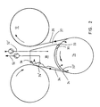
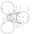
- Figure 1 shows, in a paper machine or the like, two consecutive cylinders or rolls, typically drying cylinders 10 and 12, and a turn roll 14 arranged between the cylinders.
- the turn roll can be a cylinder, a smooth roll, or a grooved roll.
- the roll may be perforated, whereby the holes of the roll are connected to a negative pressure source.
- the intensified negative pressure is typically created via the peripheral sector adjacent to the pocket space in the roll.
- the suction of the roll is generated via the axis at its end.
- the paper web 16 is arranged to run in a winding manner supported by the wire 18, alternately over a cylinder 10, 12 and alternately over the turn roll 14, so that it forms a pocket 20 between two cylinders and a turn roll.
- the wire 18 is disengaged from the periphery of the first cylinder 10 in the so called opening nip 22 and runs to the turn roll 14 so that it forms a so called input wire run 24 between the first cylinder and the turn roll.
- the wire runs from the turn roll as a so called output wire run 26 toward the second drying cylinder 12 and passes in the closing nip 28 to run over the second drying cylinder.
- the blow box 30 extending over the web is mounted in the pocket 20 so that one of its sides 32 together with the input wire run 24 forms a relatively narrow gap 34, in which the blow box creates a negative pressure.
- a blowing nozzle 36 which projects from the box 30 toward the wire 18, however without touching the wire.
- the blowing nozzle 36 is arranged in the box above the opening nip 22, i.e. so that air is discharged from the gap nozzle 38 of the nozzle mainly against the travel direction of the wire, and so that the air is discharged at a point which is above the actual disengaging point between the wire 18 and the cylinder 10, i.e. before the disengaging point in relation to the wire travel direction.
- the air discharged from the nozzle 36 prevents air travelling with the wire from entering the gap 34 between the box 30 and the wire, and further it ejects away air from the gap so that it creates negative pressure in the gap.
- the nozzle 36 is fastened to the box with the aid of a spring 42 which pushes the nozzle in a suitable way toward the wire, however so that it enables the nozzle to be pushed into the box, for instance when a paper lump passes the nozzle between the wire and the cylinder.
- a second nozzle At the other end of the blow box 30, at its lower end, there is formed a second nozzle, a simple gap-like nozzle 44, having air jets which are directed against the rotation direction of the turn roll and which thus prevent air from passing with the turn roll toward the closing nip between this roll 14 and the wire 18.
- the blows of the nozzle can also eject air away from the gap between the box and the wire.
- a suction roll for instance a VAC roll of the applicant, is used as the turn roll which in the manner shown by the arrows sucks air from the pocket region.
- a second ejecting nozzle 46 is arranged in the blow box 30 close to the closing nip 28 of the second cylinder 12, slightly after the closing nip, i.e. at a point where the wire already has engaged to the cylinder.
- the air jets of this second nozzle are directed away from the pocket, so that they are mainly in the direction of the wire travel. The air jets prevent air from entering the pocket through the gap between the nozzle and the wire. In this way a negative pressure can be maintained in the whole pocket.
- a throttling means 50 is arranged in the blow box at a short distance from the first nozzle 36, the throttling means dividing the gap 34 between the box 30 and the wire 18 into two sections, the section 34' having an intensified negative pressure and the section 34" having a lower negative pressure.
- the throttling means is a mechanical seal which prevents, or at least reduces, the air flow from the section 34" to the section 34'.
- the ejecting nozzle 36 is thus arranged to remove air mainly from a relatively small section of the pocket 20, whereby it is relatively easy to generate even a very high negative pressure in this small section 34', compared to the negative pressure in the other parts of the pocket.
- the throttle 50 it is possible to increase the negative pressure level by up to about 200 - 500 Pa, in some cases even many times more.
- the intensified negative pressure in the section 34' assists in disengagement the web from the surface of the cylinder 10, mainly in the disengaging point 40, and to attach the web firmly on the wire.
- the lower negative pressure in the section 34" is sufficient to keep the web attached to the wire until the turn roll.
- Suction is typically arranged in the turn roll in order to keep the web attached to the surface of the turn roll. The suction also affects the pocket.
- the second ejecting nozzle 46 seals the gap between the box and the second drying cylinder and ensures the negative pressure in the pocket as well as that the web does not form a pouch in the closing nip 28.
- a relatively low negative pressure e.g. 100 to 200 Pa negative pressure, may be sufficient in other parts of the pocket, except in the gap 34'.
- a low negative pressure allows for instance that the elongation of the web can spread over a large area and thus reduce wrinkling of the web.
- blowing nozzles in the box 30 there may be arranged a common blowing air supply, or an air supply which is individually controlled at each nozzle.
- a common blowing air supply or an air supply which is individually controlled at each nozzle.
- the intensified negative pressure level can be separately controlled with this nozzle.
- a suction opening 54 connected to the suction channel 52, such as a gap extending over the whole web with which more air can be removed from the intensified negative pressure region through the gap 34' when required.
- a net or the like which prevents paper lint or other rubbish from reaching the suction channel.
- the suction channel can be formed so that when a web break occurs it can be connected to a blower in order to blow air into the gap 34' in order to clean the gap.
- a resilient throttling means or a throttling means fastened resiliently to the box can be arranged in the box so that it projects very close to the wire, about 2 to 40 mm, typically ⁇ 20 mm, advantageously ⁇ 10 mm from the wire (support fabric), and thus effectively separates the negative pressure region 34' from the rest of the surrounding space.
- the distance of the nozzle 36 from the wire is short and the air jets from this nozzle are sufficient, a negative pressure is obtained at the opening nip which is sufficient for many running requirements, without any further actions.
- the blow box 30 can be shaped so that it mainly occupies the whole pocket space, i.e. so that the box extends almost from the wire run 24 up to the wire run 26.
- Figure 2 shows such a variation of Figure 1. Then the same reference numerals as in Figure 1 are used in Figure 2 when applicable.
- the lower part of the box 30 in Figure 2 is widened so that it covers a large part of the periphery of the turn roll 14. In this way the gap 34 between the box 30 and the wire run 24 and the gap 31 between the box 30 and the turn roll 14 can be made so small that they restrict or prevent the air flow.
- the distance between the box and the roll can be of the order of 10 to 30 mm.
- the gap 37 between the output wire run 26 and the box 30 has typically a width of 20 to 50 mm, but it can be made so that it widens upwards, whereby the air entering the gap is easily removed from there.
- the roll 14 can be a suction roll which sucks air from the gaps 34, 31 and 37.
- a separate air discharge via the channel 52 with the aid of a blower can be arranged in the intensified negative pressure region 34' in the box 30.
- the channel 52 it is possible to arrange in the box 30 a separate box part (not shown) with negative pressure, through which part air is removed from the intensified negative pressure region.
- air is supplied to the box 30 via the channel 52' with the aid of a blower.
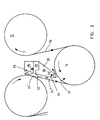
- Figure 3 shows another variation of Figure 1.
- the same reference numerals as in Figures 1 and 2 are used in Figure 3 when applicable.
- the blow box 30 of Figure 3 is smaller than the box in Figure 1, and it does not extend the whole distance to the second drying cylinder 12.
- a box of this kind can be used if it is not necessary to create a negative pressure with the aid of the box at the wire run 26 between the turn roll 14 and the second drying cylinder.
- the ejecting nozzles 36 and 44 of the box 30 are connected to different blow chambers 36', 44', and they can be controlled individually.
- the Coanda surface of the ejecting nozzle 44 which is arranged against the curved roll and which removes air from the closing nip between the roll 14 and the wire run 24, acts at the same time as a seal in the gap between the roll 14 and the box 30.
- a resilient throttling means 50 divides the negative pressure region into two sections 34', 34", where it is possible to maintain different negative pressure levels.
- the throttling means 50 can be, for instance, similar to the mechanical throttling means shown in Figure 9.
- the nozzle 44 can be replaced by a mechanical seal like the means 50, if desired.
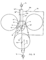
- FIG 4 shows another blowing device according to the invention in the same way as in the Figure 1.
- the same reference numerals as in the previous Figures are used when applicable.
- the blowing device comprises a two-part blow box combination which is formed by a lower and an upper box section 30', 30".
- an ejecting nozzle 36 In the upper box section 30' there is arranged an ejecting nozzle 36, a suction opening 54 and a throttling means 50, as in the solution of Figure 1.
- the throttling means 50 is an ejecting nozzle, for instance a nozzle similar to that of the first ejecting nozzle 36, which is arranged to eject air away from the lower part of the gap 34' in order to create an intensified negative pressure in the gap.
- the ejecting nozzle 50 which creates the seal comprises a convex surface, a so called Coanda surface, along which the ejecting air jets are guided out from the gap 34'.
- the convex surface guides the ejecting air jets and at least a part of the air which is removed by ejection from the space 34', into the discharge channel 56 formed between the box sections 30', 30" with which the air is discharged from the pocket.
- the negative pressure can be maintained in the second, lower section 34" of the gap with the aid of a second nozzle 44, which is arranged in the lower section 30" of the box structure to eject air into the discharge channel 56 and from there further to the space surrounding the drying cylinders.
- Figure 4 presents an ejecting nozzle 44 which is a simple gap nozzle and which is arranged at the beginning of the discharge channel 56 to blow air directly into the discharge channel. The air from the nozzle sucks with it air which flows out from the gap 34'.
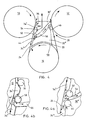
- Figure 4a shows a first variation of the nozzle 44 in Figure 4.
- an ejecting nozzle provided with a curved surface is arranged close to the wire run 24 in the box structure 30", i.e. the nozzle is similar to the nozzles 36, 46 and 50 in Figure 4.
- This nozzle 44 is arranged to blow air through the gap between the nozzle 44 and the wire run toward the discharge channel 56.
- the air blown with the nozzle 44 prevents the air, which is blown out through the first gap with the aid of the throttling means 50, from flowing into the lower gap 34", and also the air from flowing from the gap 34" upstreams in relation to the wire run.
- Figure 4b shows a second modification of the solution in Figure 4.
- the solution of Figure 4b uses a sealing air guide 44' instead of the ejecting nozzle 44, to prevent air flow between the gaps 34' and 34".
- a sealing ledge 33 or the like can be arranged, at the beginning of the gap 58 formed between the turn roll 14 and the bottom surface of the box 30" as seen in the direction of the travelling direction of the roll, so that the ledge prevents or at least reduces the air flow conveyed by the turn roll.
- the sealing can also be provided by shaping the box 30' so that its bottom surface projects very close to the roll. Also in this way it is possible to prevent or at least reduce the air flow between different parts of the pocket.
- the sealing ledge 33 the sealing can also be provided by an ejecting nozzle, e.g. by replacing the sealing ledge 33 with the nozzle 46 of Figure 4.
- a higher or intensified negative pressure is created in the gap 34' between the box 30 and the wire run 24, with the aid of two ejecting nozzles 36 and 50.
- the intensified negative pressure is typically about 500 to 900 Pa higher than the negative pressure in other parts of the pocket.
- the nozzle 36 removes air from the gap by ejection, and at the same time it prevents the air conveyed by the wire from flowing into the gap.
- the nozzle 50 removes also air by ejection.
- the ejecting air jets further create a protection between the wire and the nozzles preventing them from touching each other, even if the wire would be slightly slackened.
- the nozzle 46 on the other side of the box ejects air from the pocket space assisting in maintaining a suitable negative pressure level in the pocket.
- Figure 5 shows a blow box combination which largely is similar to that of the Figure 4 and uses the same reference numerals.
- the two-part box structure 30', 30" fills a large part of the pocket, whereby between the box and the wire runs 24, 26 there is left a relatively small region where a negative pressure is to be applied.
- the box structure has no separate ejecting nozzle 44 to remove air from the gap 34" into the discharge channel 56, as in the case of Figure 4.
- air is removed from the gap 34" into the turn roll 14 acting as a suction roll, as is the case also in Figure 4.
- a suction opening communicating with means generating the suction, as is shown with the broken lines. More air can be discharged through this closing nip via the suction opening.
- flow preventing means at the lower edge 64 of the box.
- Blades or plates 66, 66' at the lower edge of the box, and the wave-formed surface of the lower edge form a labyrinth seal between the lower edge of the box and the roll 14, the seal preventing or substantially reducing the air flow in the gap between these.
- the discharged air in the channel 56 is directed close to the closing nip 28 between the second cylinder 12 and the wire run 26 into the negative pressure space close to the second ejecting nozzle 46.
- the ejecting nozzle 46 removes the air discharged via the channel 56 from the negative pressure space.
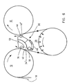
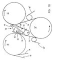
- FIG. 6 shows a third box solution according to the invention using the same reference numerals as in the previous Figures.
- the box 30 is arranged mainly between on one hand the disengaging point 40 between the first drying cylinder 10 and the wire 18 and on the other hand the engaging point 40' between the second drying cylinder 12 and the wire.
- the negative pressure in the pocket 20 is generated with the aid of the suction effect of the roll and in addition with the aid of an ejecting nozzle 36 mounted above the disengaging point 40 in the top part of the first side of the box, and with an ejecting nozzle 46 mounted above the engaging point 40' in the upper part of the second side of the box.
- a higher negative pressure is created in the intensified negative pressure region with an ejecting nozzle 50 according to the Figure 4 or 5.
- the air removed from the gap 34' with the aid of the ejecting nozzle 50 is directed with the aid of the guide plate 68 toward the ejecting nozzle 46 on the other side of the box.
- the use of the suction is possible in the solutions according to the invention because a strong blow with the nozzles 36 against the travelling direction of the wire reduces or completely prevents the passage of dust, paper lint or the like into the suction means.
- Figure 7 shows a blow box 30' like that in Figure 6, but which however is connected to a lower box section 30" having a curved surface 70 mounted in the bottom of it covering a large part of the periphery of the turn roll 14 left within the pocket 20.
- the turn roll is a suction roll which maintains a negative pressure in the pocket in the lower negative pressure region of the pocket. Air is removed from the pocket into the suction roll in the manner shown by the arrows, through those parts 72 of the suction roll's periphery which are not covered by the curved surface of the box.
- a damper 47 is arranged between the box sections 30', 30", whereby the air flows coming from different sides of the pocket can be controlled by the damper.
- the lower box 30" of Figure 7 can, when required, be a suction box with a width corresponding basically to the whole width of the pocket, which suction box creates a negative pressure in the roll 14. Then there are orifices in the lower part of the suction box 30", and its lower part is curved so that it follows the form of the turn roll 14 so that a narrow space 68 is left between the suction box and the roll. The edges of the space at the wire runs are sealed by mechanical means 66, 66'. When the surface of the turn roll is open, e.g. perforated, the suction box can generate a negative pressure in the turn roll.
- the turn roll can be arranged to suck air from the gaps between the wire runs 24, 26 and the suction box, so that a required negative pressure, regarding the run of the wire, is formed in the gaps.
- Figure 8 shows a blow box 30 similar to that of Figure 6, as well as communicating channels, with which the desired air flows are provided in the nozzles 36, 46, 50 and in the suction opening 54.
- the air chambers 36', 46' and 50' of the ejecting nozzles 36, 46 and 50 within the boxes are connected to the blower 74 through channels 36", 46" and 50". Some or all of the channels can be provided with control valves for controlling the air jets.
- the Figure 8 further shows a suction chamber 54' communicating with the suction orifice 54, and a channel 54" with which the suction chamber communicates with means 76 creating the suction.
- the turn roll 14 communicates via the channel 15 with the means 76 creating the suction.
- the suction from the suction orifice 54 can be closed by closing the valve 54a in the channel 54".
- a blow may be provided from the suction orifice 54 by closing the valve in the channel 46" and by opening the valve 78a in the channel 78, whereby blowing air flows from the blower via the channels 78 and 54" to the suction orifice 54.
- Figure 9 shows an enlargement of the intensified negative pressure region 34' of the type in Figure 1.
- Air is ejected away from the region 34' with the ejector 36. Further it is possible to suck air from the region 34' via the suction orifice 54.
- a net 55 or the like is mounted in front of the suction orifice, the net preventing impurities from reaching the suction channel 52.
- the mechanical throttling means 50 is a wave-shaped blade or ledge 51' projecting toward the wire 18 with the aid of a spring 51.
- This blade 51' can have the shape of a smooth arc, i.e. without any wave-form.
- Several such blades or ledges can be arranged in a row in the gap 34', in order to create a non-continuous pressure difference in the gap.
- FIG 9 it can be seen how the air flowing out from the ejecting nozzle 36 meets the air flow conveyed with the wire, which then is at least partly deflected.
- the ejecting air jets draw with them other air from the negative pressure region 34', where the negative pressure is thus intensified.
- the throttling means 50 which forced by the spring projects relatively close to the wire 18, prevents air from penetrating from the outside of the intensified negative pressure region into the gap 34'.
- the corrugated surface of the throttling means intensifies this preventive effect as it forms turbulence between the means and the wire.
- the throttling means 50 can be an ejecting nozzle, which is e.g. in accordance with the nozzle 36 in Figure 9, but from which the air flows in the opposite direction, i.e. in the travelling direction of the wire.
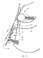
- the solution according to the invention is applied in a drying section provided with a twin wire run.
- the upper wire 18 of the drying section passes in a winding manner from the first drying cylinder 10 to the second one 12 via the turn roll 14 of the wire.
- a pocket 20 defined by the wire and the turn roll.
- a blow box 30 which is mainly similar to that of Figure 3 and in which the ejecting nozzle 36 and the throttle 50 define an intensified negative pressure region 34' at the wire disengaging point.
- a second blowing nozzle 46 is also arranged in the blow box in order to prevent leaking air from flowing into the pocket space.
- a corresponding blow box according to the invention can be used in the drying section shown in Figure 10, in the region of the lower wire run for disengagement the web 16 from the lower drying cylinder 10' so that it runs on the lower wire 18' over a short distance.
- the invention makes it possible to control the negative pressure level at the opening nip according to the machine speed, the dry solids content of the paper and/or the paper quality, whereby the runability of the paper and the efficiency of the drying section can be optimised to a considerably better degree than previously.
- By controlling the negative pressure level at the intensified negative pressure region it is also often possible to use pulp which has a lower quality than conventionally, e.g. minor amounts of chemical pulp, without having a negative effect on the runability.
- a part of the fibres may be replaced by filler which is cheaper than fibre.
- a part of the additives can be replaced by cheaper filler materials.
- a suitably high negative pressure level will ensure that the web is disengaged from the drying cylinder.
- the negative pressure regions can, of course, be sealed also in the transversal direction of the web, e.g. with end seals which can be mechanical seals or edge nozzles.
- the intensified negative pressure region can extend across the web, or only over a part of the web in its transversal direction.
- the intensified negative pressure region can be arranged e.g. only at the edge regions of the web, or only on the front side in the threading region. In addition to the control of the negative pressure in the intensified negative pressure region according to the running conditions, it is possible to control it differently at different locations of the web in its transversal direction.
- the invention is applied also in other drying sections than in drying sections provided with a single wire run. It is possible to apply the invention, when desired, also in other parts of a paper machine where the web must be disengaged from a roll or the like and conveyed forward supported by a wire or the like within a negative pressure space, in which it is difficult to increase the negative pressure level.
Claims (21)
- Dispositif de soufflage dans une machine à papier ou analogue, telle qu'une machine à carton ou un raffineur, dans lequel la bande (16) est transportée sur un cylindre (10, 12), tel qu'un cylindre sécheur ou un autre rouleau, maintenue par une toile support, telle qu'une toile métallique (18) ou analogue, entre le cylindre et la toile support, le dispositif de soufflage comprenant un caisson de soufflage (30) ou une combinaison de caissons de soufflage (30', 30") se prolongeant sur toute la largeur de la bande et étant connectè à des moyens (74) générant de l'air de soufflage, et le dispositif de soufflage étantgrâce auquel les moyens d'étanchéité maintiennent une dépression dans l'espace situé entre le dispositif de soufflage et la bande,agencé sur le côté de la toile support (18) qui est à l'opposé du cylindre (10) en grande partie sur la ligne de contact ouvrante (22) ou analogue située entre la toile support et le cylindre de façon à ce qu'il se prolonge depuis cette ligne de contact ou analogue au moins sur une courte distance vers l'avant dans la direction de passage de la toile support, etfourni avec au moins deux organes d'étanchéité (33, 36, 44, 46, 66), tels que des tuyères d'espacement, des tuyères d'éjection, des garnitures mécaniques ou analogues, disposées transversalement et regardant dans la direction de passage de la bande, les organes d'étanchéité étant agencés dans le dispositif de soufflage de façon à ce queun premier organe d'étanchéité consistant en une tuyère (36) soit agencé dans le caisson de soufflage près de la toile support, en grande partie sur la ligne de contact ouvrante (22) ou analogue située entre la toile support et le cylindre pour souffler des jets d'air hors de l'ouverture (34) située entre la toile support et le dispositif de soufflage, etdes seconds moyens d'étanchéité (33, 44, 46, 66) soient agencés dans le caisson de soufflage près de la toile support (18) ou du rouleau (14) faisant tourner la toile support à une certaine distance de la ligne de contact ouvrante susmentionnée ou analogue dans la direction de passage de la toile support,
caractérisé en ce quedans le dispositif de soufflage à une courte distance de la ligne de contact ouvrante ou analogue sont en outre agencés des moyens d'étranglement (50) projetant l'air vers la toile support, les moyens d'étranglement divisant l'espace de dépression formé entre les premiers et seconds moyens d'étanchéité enune première zone de dépression d'amplification (34') limitée à un endroit sur la ligne de contact ouvrante ou analogue, etune seconde zone de dépression plus petite (34", 20'). - Dispositif de soufflage selon la revendication 1, caractérisé en ce que les seconds moyens d'étanchéité sont une tuyère (44, 46).
- Dispositif de soufflage selon la revendication 2 dans une partie de séchage de la bande dotée d'un passage de toile métallique simple,
caractérisé en ce quele dispositif de soufflage est un caisson de soufflage (36) qui est en grande partie agencé près du point de dégagement (40) situé entre le cylindre sécheur et la toile métallique ; et en ce quela seconde tuyère (44) du caisson de soufflage est agencée près de la ligne de contact fermante située entre le rouleau de retour de toile et la toile métallique, de façon à ce que les jets d'air éjectés de cette tuyère (44) aspirent par effet d'éjection l'air hors de la ligne de contact fermante et de l'espace (34") situé entre le caisson de soufflage et la toile métallique. - Dispositif de soufflage selon la revendication 3, caractérisé en ce que dans le caisson de soufflage situé entre la première tuyère (36) et les moyens d'étranglement (50) est agencé un orifice d'aspiration (54) qui est raccordé à des dispositifs créant une aspiration afin d'amplifier la dépression dans la zone de dépression d'amplification (34').
- Dispositif de soufflage selon la revendication 2 dans une partie de séchage de la bande dotée d'un passage de toile métallique simple,
caractérisé en ce qued'autre part la ligne de contact fermante (28) située entre le second cylindre sécheur (12) et la toile métallique (18), et en ce quele dispositif de soufflage est un caisson de soufflage (36) qui est agencé dans la poche (20) formée entre deux cylindres sécheurs (10, 12) et le rouleau de retour de toile (14), entre d'une part la ligne de contact ouvrante (22) entre le premier cylindre sécheur (10) et la toile métallique (18) etla seconde tuyère (46) du caisson de soufflage est agencée près de la ligne de contact fermante située entre le second cylindre sécheur (12) et la toile métallique, de façon à ce queles jets d'air éjectés de cette tuyère aspirent par effet d'éjection l'air hors de la poche (20). - Dispositif de soufflage selon la revendication 5, caractérisé en ce que dans le caisson de soufflage situé entre la première tuyère (36) et les moyens d'étranglement (50) est agencé un orifice d'aspiration (54) qui est raccordé à des dispositifs créant une aspiration afin d'augmenter la dépression dans la zone de dépression d'amplification (34').
- Dispositif de soufflage selon la revendication 1, caractérisé en ce que les moyens d'étranglement (50) comprennent une tuyère d'éjection agencée dans le caisson de soufflage et projetant l'air vers la toile support, la tuyère d'éjection étant agencée de façon à éjecter au moyen de jets d'air l'air hors de la zone de dépression d'amplification (34') dans la seconde zone de dépression (34') ou entiérement hors de l'espace de dépression.
- Dispositif de soufflage selon la revendication 7, caractérisé en ce que dans les moyens d'étranglement (50) est agencée une surface convexe qui guide les jets d'air d'éjection hors de la zone de dépression d'amplification (34") en utilisant l'effet Coanda.
- Dispositif de soufflage selon la revendication 8, caractérisé en ce qu'une plaque de guidage (68) est agencee entre d'une part les moyens d'étranglement (50) et d'autre part la ligne de contact fermante située entre le rouleau de retour de toile et la toile support, pour empêcher l'air éjecté au moyen de la tuyère d'éjection d'atteindre ladite ligne de contact fermante.
- Dispositif de soufflage selon la revendication 1, caractérisé en ce que les moyens d'étranglement (50) comprennent des moyens mécaniques d'étanchéité, tels que des moyens restreignant le flux d'air, les moyens se prolongeant sur la largeur de la bande et étant montés sur ressorts ou sur pivot dans le caisson de soufflage afin de maintenir une dépression d'amplification dans la zone de dépression d'amplification.
- Dispositif de soufflage selon la revendication 10, caractérisé en ce que les moyens d'étranglement (50) possèdent une surface qui est dirigée contre la toile support et qui est ondulée.
- Dispositif de soufflage selon la revendication 1, caractérisé en ce que la première tuyère (36) et les moyens d'étranglement (50) sont intégrés dans une structure commune recouvrant la zone de dépression d'amplification (34"), la structure étant agencée sur pivot et/ou sur ressorts à une courte distance de la toile support passant sur la ligne de contact ouvrante.
- Dispositif de soufflage selon la revendication 1, caractérisé en ce que les moyens d'étranglement sont agencés pour se prolonger sur une distance de 2 à 40 mm, généralement inférieure à 20 mm, idéalement inférieure à 10 mm de la toile support.
- Dispositif de soufflage selon la revendication 1, caractérisé en ce que la longueur de la zone de dépression d'amplification (34') située entre la première tuyère et les moyens d'étranglement (50) mesure entre 50 et 500 mm, généralement 100 à 200 mm, dans la direction de passage de la toile support.
- Dispositif de soufflage selon la revendication 1, caractérisé en ce quela première tuyère (36) est agencée à une distance inférieure à 300 mm, généralement 40 à 150 mm, idéalement à environ 70 mm du point de dégagement (40) de la toile support, avant ce point de dégagement regardant dans la direction de la toile support, et en ce queles moyens d'étranglement (50) sont agencés à une distance d'environ 40 à 250 mm, généralement 80 à 120 mm, idéalement à environ 100 mm du point de dégagement de la toile support, après le point de dégagement de la toile support regardant dans la direction de passage de la toile support.
- Dispositif de soufflage selon la revendication 1 dans une partie de séchage de la bande dotée d'un passage de toile métallique simple,
caractérisé en ce quele dispositif de soufflage comprend une première partie du caisson de soufflage (30') et une seconde partie du caisson (30") qui sont agencees dans la poche (20) formée entre deux cylindres sécheurs (10, 12) et un rouleau de retour de toile (14), tel qu'un rouleau à vide ou autre cylindre aspirant, entre d'une part la ligne de contact ouvrante (22) située entre le premier cylindre sécheur et la toile métallique et d'autre part la ligne de contact fermante (28) située entre le second cylindre sécheur et la toile métallique,la première partie du caisson de soufflage (30') est agencée avant la ligne de contact ouvrante,la première tuyère (36) et les moyens d'étranglement (50) sont agencés dans la première partie du caisson de soufflage,la seconde partie du caisson (30") est agencée pour recouvrir au moins une partie de la surface bordant la poche du rouleau de retour de toile, et en ce queentre la première partie du caisson de soufflage (30') et la seconde partie du caisson (30") est formé un canal d'éjection de l'air (56) pour diriger l'air éjecté de la zone de dépression d'amplification hors de l'espace de dépression. - Dispositif de soufflage selon la revendication 16, caractérisé en ce queles moyens d'étranglement (50) comprennent une tuyère d'éjection dotée d'une surface de sortie convexe et agencée à l'extrémité de la première partie du caisson de soufflage, la tuyère d'éjection étant agencèe pour éjecter l'air hors de la zone de dépression d'amplification au moyen de jets d'air, et en ce quel'ouverture d'entrée du canal d'éjection de l'air (56) est agencée près de la surface de sortie convexe de la tuyère d'éjection, de façon à ce que l'air passant le long de la surface convexe soit guidé directement vers le canal d'éjection de l'air par effet Coanda.
- Dispositif de soufflage selon la revendication 16, caractérisé en ce que la surface (64) de la seconde partie du caisson (30") dirigée vers le rouleau de retour de toile est ondulée.
- Dispositif de soufflage selon la revendication 16, caractérisé en ce que la seconde partie du caisson (30") est un caisson de soufflage possédant une tuyère (46), qui est agencée près de la ligne de contact fermante du second cylindre sécheur.
- Dispositif de soufflage selon la revendication 1, caractérisé en ce que les seconds moyens d'étanchéité sont des moyens mécaniques (33, 66) restreignant le flux d'air, et en ce que le rouleau est un cylindre aspirant.
- Dispositif de soufflage selon la revendication 1 dans la partie de séchage dotée d'un passage dc toile métallique double, caractérisé en ce quele dispositif de soufflage est un caisson de soufflage (36) qui est agencé dans la poche (20) formée entre deux cylindres sécheurs (10, 12) et le rouleau de retour de toile (14), entre d'une part la ligne de contact ouvrante (22) située entre le premier cylindre sécheur (10) et la toile métallique supérieure ( 18) et d'autre part la ligne de contact fermante (28) située entre le second cylindre sécheur (12) et la toile métallique supérieure (18), et en ce quela seconde tuyère (46) du caisson de soufflage est agencée près de la ligne de contact fermante située entre le second cylindre sécheur (12) et la toile métallique supérieure, de façon à ce queles jets d'air éjectés de cette tuyère aspirent l'air hors de la poche (20) par effet d'éjection.
Applications Claiming Priority (3)
| Application Number | Priority Date | Filing Date | Title |
|---|---|---|---|
| FI990370A FI110625B (fi) | 1999-02-22 | 1999-02-22 | Puhalluslaite paperikoneessa tai vastaavassa |
| FI990370 | 1999-02-22 | ||
| PCT/FI2000/000130 WO2000050693A1 (fr) | 1999-02-22 | 2000-02-21 | Appareil de soufflage dans une machine a papier ou analogue |
Publications (2)
| Publication Number | Publication Date |
|---|---|
| EP1155189A1 EP1155189A1 (fr) | 2001-11-21 |
| EP1155189B1 true EP1155189B1 (fr) | 2004-06-09 |
Family
ID=8553883
Family Applications (2)
| Application Number | Title | Priority Date | Filing Date |
|---|---|---|---|
| EP00906388A Expired - Lifetime EP1194641B1 (fr) | 1999-02-22 | 2000-02-21 | Procede et appareil concernant la section sechage d'une machine a papier ou equivalent |
| EP00906389A Expired - Lifetime EP1155189B1 (fr) | 1999-02-22 | 2000-02-21 | Appareil de soufflage dans une machine a papier ou analogue |
Family Applications Before (1)
| Application Number | Title | Priority Date | Filing Date |
|---|---|---|---|
| EP00906388A Expired - Lifetime EP1194641B1 (fr) | 1999-02-22 | 2000-02-21 | Procede et appareil concernant la section sechage d'une machine a papier ou equivalent |
Country Status (16)
| Country | Link |
|---|---|
| US (2) | US6910282B1 (fr) |
| EP (2) | EP1194641B1 (fr) |
| JP (3) | JP3574791B2 (fr) |
| KR (2) | KR100460517B1 (fr) |
| CN (2) | CN1188571C (fr) |
| AT (2) | ATE268831T1 (fr) |
| AU (2) | AU2807400A (fr) |
| CA (2) | CA2371804C (fr) |
| CZ (2) | CZ20013030A3 (fr) |
| DE (4) | DE1155189T1 (fr) |
| DK (1) | DK1194641T3 (fr) |
| ES (2) | ES2169711T3 (fr) |
| FI (2) | FI110625B (fr) |
| PL (2) | PL195509B1 (fr) |
| PT (2) | PT1155189E (fr) |
| WO (2) | WO2000050692A1 (fr) |
Cited By (1)
| Publication number | Priority date | Publication date | Assignee | Title |
|---|---|---|---|---|
| EP2607548A1 (fr) * | 2011-12-20 | 2013-06-26 | Metso Paper Inc. | Élément pour contrôler le cheminement d'une bande de papier dans la sécherie d'une machine à papier et procédé pour sécher une bande de papier |
Families Citing this family (36)
| Publication number | Priority date | Publication date | Assignee | Title |
|---|---|---|---|---|
| FI110625B (fi) | 1999-02-22 | 2003-02-28 | Metso Paper Inc | Puhalluslaite paperikoneessa tai vastaavassa |
| FI114935B (fi) * | 2000-06-09 | 2005-01-31 | Metso Paper Inc | Menetelmä ja järjestelmä paperikoneessa tai vastaavassa rainan siirtämiseksi puristinosalta kuivatusosalle |
| FI111174B (fi) | 2000-10-27 | 2003-06-13 | Metso Paper Inc | Menetelmä ja laite rainan päänviennissä paperikoneen tai vastaavan kuivatusosassa |
| FI118811B (fi) * | 2000-11-06 | 2008-03-31 | Metso Paper Inc | Päällepuhalluskuivatusyksikkö ja kuivatusosa |
| DE10140801A1 (de) * | 2001-08-20 | 2003-03-06 | Voith Paper Patent Gmbh | Vorrichtung zur Behandlung einer Faserstoffbahn |
| FI111280B (fi) | 2001-11-08 | 2003-06-30 | Metso Paper Inc | Puhalluslaatikko rainan kulun ohjaamiseksi |
| FI120746B (fi) | 2001-12-19 | 2010-02-15 | Metso Paper Inc | Paperi- tai kartonkikoneen kuivatusosa |
| JP3723158B2 (ja) | 2002-05-30 | 2005-12-07 | 三菱重工業株式会社 | ドライヤ真空ボックス |
| FI115232B (fi) | 2002-11-19 | 2005-03-31 | Metso Paper Inc | Tiivistejärjestely liikkuvaa kudosta vasten |
| FI119152B (fi) * | 2004-06-03 | 2008-08-15 | Metso Paper Inc | Menetelmä ja sovitelma paperikoneessa tai vastaavassa kuivatettavan, yleensä viiraa vasten tuetun liikkuvan rainan läheisyydessä, tiivistyslaite sekä paperikone |
| FI20050596A0 (fi) * | 2005-06-06 | 2005-06-06 | Metso Paper Inc | Järjestely ja menetelmä kuivatussylinterien välisen taskutilan tiivistämiseksi paperikoneessa tai vastaavassa |
| US20070193057A1 (en) * | 2006-01-26 | 2007-08-23 | Girolamo Paul A | Rotatable vacuum transfer roll apparatus |
| US20070180729A1 (en) * | 2006-01-26 | 2007-08-09 | Girolamo Paul A | Blow box apparatus |
| FI20065061L (fi) * | 2006-01-30 | 2007-07-31 | Metso Paper Inc | Menetelmä ja laite kuiturainakoneen, kuten paperi- tai kartonkikoneen kuivatusosassa |
| FI119029B (fi) * | 2006-01-30 | 2008-06-30 | Metso Paper Inc | Menetelmä ja laite kuiturainakoneen, kuten paperi- tai kartonkikoneen kuivatusosassa |
| FI124219B (fi) | 2007-11-14 | 2014-05-15 | Valmet Technologies Inc | Kaavinlaitteisto päänvientinauhan irrottamiseksi liikkuvasta pinnasta kuiturainakoneella |
| WO2009083636A1 (fr) * | 2007-12-31 | 2009-07-09 | Metso Paper, Inc. | Configuration et procédé pour économiser de l'énergie dans la section de séchage d'une machine à papier ou similaire |
| AT506408B1 (de) * | 2008-06-17 | 2009-09-15 | Andritz Ag Maschf | Vorrichtung und verfahren zur überführung einer materialbahn |
| AT506409B1 (de) * | 2008-06-17 | 2009-09-15 | Andritz Ag Maschf | Vorrichtung und verfahren zur überführung einer materialbahn |
| AT506407B1 (de) * | 2008-06-17 | 2009-09-15 | Andritz Ag Maschf | Vorrichtung und verfahren zur überführung einer materialbahn |
| SE532624C2 (sv) * | 2008-06-19 | 2010-03-09 | Andritz Technology And Asset Management Gmbh | Kylning av en cellulosamassabana |
| FI124037B (fi) * | 2008-09-03 | 2014-02-14 | Ev Group Oy | Laite sekä menetelmä paperin irtoamisen parantamiseksi paperikoneen kuivatussylinteriltä |
| FI20095042A (fi) * | 2009-01-20 | 2010-07-21 | Metso Paper Inc | Menetelmä ja järjestely rainan päänviennin helpottamiseksi paperikoneen kuivatusosalla |
| CN101487198B (zh) * | 2009-02-10 | 2011-07-20 | 湖南正大轻科机械有限公司 | 高速纸机纸幅稳定器 |
| FI124766B (fi) * | 2010-06-30 | 2015-01-15 | Valmet Technologies Inc | Menetelmä kuiturainan käyristymän hallitsemiseksi ja kuiturainakoneen kuivatusosa |
| FI124504B (fi) * | 2011-03-08 | 2014-09-30 | Valmet Technologies Inc | Ajettavuuskomponentti ja menetelmä paperikoneen ajettavuuskomponentin käyttötehokkuuden parantamiseksi |
| EP2803765A1 (fr) * | 2013-05-17 | 2014-11-19 | Brunnschweiler S.A. | Procédé et système pour la stabilisation de papier applicable dans des machines et procédés à sécher le papier |
| US11429121B2 (en) | 2013-07-12 | 2022-08-30 | Best Technologies, Inc. | Fluid flow device with sparse data surface-fit-based remote calibration system and method |
| CA2919507C (fr) | 2013-07-12 | 2023-03-07 | John C. Karamanos | Dispositif de mesure de regulation de fluide |
| US10030882B2 (en) | 2013-07-12 | 2018-07-24 | Best Technologies, Inc. | Low flow fluid controller apparatus and system |
| US11815923B2 (en) | 2013-07-12 | 2023-11-14 | Best Technologies, Inc. | Fluid flow device with discrete point calibration flow rate-based remote calibration system and method |
| CN103750534A (zh) * | 2013-12-19 | 2014-04-30 | 云南中烟昆船瑞升科技有限公司 | 一种再造烟叶片基转移装置 |
| SE538854C2 (sv) * | 2014-01-09 | 2017-01-03 | Valmet Oy | Rullstol för mottagande och upprullning av en pappersbana, som kommer från en torkcylinder i en pappersmaskin, till en rulle, samt en pappersmaskin som använder en rullstol |
| US10434796B2 (en) * | 2017-03-17 | 2019-10-08 | Ricoh Company, Ltd. | Dryer, printer, and liquid applicator |
| DE102019124500A1 (de) * | 2019-09-12 | 2020-09-10 | Voith Patent Gmbh | Vorrichtung zur Trocknung einer Faserstoffbahn |
| CN114541166B (zh) * | 2022-01-29 | 2024-03-08 | 江苏理文造纸有限公司 | 一种可形成双级真空区的稳纸箱及造纸机 |
Family Cites Families (14)
| Publication number | Priority date | Publication date | Assignee | Title |
|---|---|---|---|---|
| US4359827B1 (en) | 1979-11-05 | 1994-03-29 | Keith V Thomas | High speed paper drying |
| FI59637C (fi) | 1979-11-20 | 1981-09-10 | Valmet Oy | Anordning i torkpartiet av en pappersmaskin |
| JPH01501952A (ja) | 1986-04-08 | 1989-07-06 | ベロイト・コーポレイション | 乾燥機用ブロー・ボックス |
| FI80491C (fi) | 1987-09-02 | 1990-06-11 | Valmet Paper Machinery Inc | Foerfarande och torkningsgrupp i maongcylindertorken av en pappersmaskin. |
| DE3914761A1 (de) | 1989-03-08 | 1990-11-15 | Voith Gmbh J M | Leitwalze fuer ein poroeses band, beispielsweise fuer ein trockensieb einer papiermaschine |
| FI82850C (fi) * | 1989-03-21 | 1991-04-25 | Valmet Paper Machinery Inc | Foerfarande och anordning i torkningspartiet av en belaeggningsmaskin eller pappersmaskin. |
| DE9110134U1 (fr) | 1991-08-16 | 1991-09-26 | J.M. Voith Gmbh, 7920 Heidenheim, De | |
| DE4141296A1 (de) | 1991-12-14 | 1993-06-17 | Voith Gmbh J M | Vorrichtung zur abnahme einer bahn von einem trockenzylinder |
| WO1994003675A1 (fr) * | 1992-07-31 | 1994-02-17 | J.M. Voith Gmbh | Agencement avec un cylindre aspirant |
| US5515619A (en) * | 1993-08-06 | 1996-05-14 | J.M. Voith Gmbh | Flexibly mounted sealing strips of a vacuum roll for a web dryer |
| US5535527A (en) | 1995-06-07 | 1996-07-16 | Valmet Corporation | Method and arrangement in a multi-cylinder dryer of a paper machine |
| DE29601543U1 (de) | 1996-01-30 | 1996-03-28 | Voith Sulzer Papiermasch Gmbh | Vorrichtung zum Führen einer Faserstoffbahn in einer einreihigen Trockenpartie |
| FI110625B (fi) | 1999-02-22 | 2003-02-28 | Metso Paper Inc | Puhalluslaite paperikoneessa tai vastaavassa |
| FI4349U1 (fi) * | 1999-10-22 | 2000-02-28 | Valmet Corp | Paperikoneen kuivatusosassa käytettävään puhalluslaatikkoon sovitettav a tiivistävä suutin |
-
1999
- 1999-02-22 FI FI990370A patent/FI110625B/fi not_active IP Right Cessation
- 1999-09-08 FI FI991908A patent/FI106568B/fi not_active IP Right Cessation
-
2000
- 2000-02-21 CN CNB008041547A patent/CN1188571C/zh not_active Expired - Lifetime
- 2000-02-21 PL PL00364775A patent/PL195509B1/pl unknown
- 2000-02-21 CA CA002371804A patent/CA2371804C/fr not_active Expired - Lifetime
- 2000-02-21 AT AT00906389T patent/ATE268831T1/de active
- 2000-02-21 AU AU28074/00A patent/AU2807400A/en not_active Abandoned
- 2000-02-21 EP EP00906388A patent/EP1194641B1/fr not_active Expired - Lifetime
- 2000-02-21 ES ES00906389T patent/ES2169711T3/es not_active Expired - Lifetime
- 2000-02-21 PT PT00906389T patent/PT1155189E/pt unknown
- 2000-02-21 DE DE1155189T patent/DE1155189T1/de active Pending
- 2000-02-21 DE DE60011397T patent/DE60011397T2/de not_active Expired - Lifetime
- 2000-02-21 CA CA002362186A patent/CA2362186C/fr not_active Expired - Lifetime
- 2000-02-21 KR KR10-2001-7010710A patent/KR100460517B1/ko not_active IP Right Cessation
- 2000-02-21 WO PCT/FI2000/000129 patent/WO2000050692A1/fr active IP Right Grant
- 2000-02-21 PT PT00906388T patent/PT1194641E/pt unknown
- 2000-02-21 CZ CZ20013030A patent/CZ20013030A3/cs unknown
- 2000-02-21 ES ES00906388T patent/ES2173050T3/es not_active Expired - Lifetime
- 2000-02-21 DE DE60020238T patent/DE60020238T2/de not_active Expired - Lifetime
- 2000-02-21 CN CN00804155A patent/CN1119454C/zh not_active Expired - Lifetime
- 2000-02-21 DK DK00906388T patent/DK1194641T3/da active
- 2000-02-21 WO PCT/FI2000/000130 patent/WO2000050693A1/fr active IP Right Grant
- 2000-02-21 US US09/913,901 patent/US6910282B1/en not_active Expired - Lifetime
- 2000-02-21 JP JP2000601247A patent/JP3574791B2/ja not_active Expired - Fee Related
- 2000-02-21 US US09/913,915 patent/US6574884B1/en not_active Expired - Lifetime
- 2000-02-21 CZ CZ20013031A patent/CZ20013031A3/cs unknown
- 2000-02-21 EP EP00906389A patent/EP1155189B1/fr not_active Expired - Lifetime
- 2000-02-21 KR KR10-2001-7010709A patent/KR100460518B1/ko not_active IP Right Cessation
- 2000-02-21 JP JP2000601246A patent/JP3800316B2/ja not_active Expired - Fee Related
- 2000-02-21 DE DE1194641T patent/DE1194641T1/de active Pending
- 2000-02-21 AU AU28075/00A patent/AU2807500A/en not_active Abandoned
- 2000-02-21 PL PL364691A patent/PL194976B1/pl unknown
- 2000-02-21 AT AT00906388T patent/ATE295913T1/de active
-
2005
- 2005-04-18 JP JP2005120134A patent/JP2005248416A/ja not_active Withdrawn
Cited By (1)
| Publication number | Priority date | Publication date | Assignee | Title |
|---|---|---|---|---|
| EP2607548A1 (fr) * | 2011-12-20 | 2013-06-26 | Metso Paper Inc. | Élément pour contrôler le cheminement d'une bande de papier dans la sécherie d'une machine à papier et procédé pour sécher une bande de papier |
Also Published As
Similar Documents
| Publication | Publication Date | Title |
|---|---|---|
| EP1155189B1 (fr) | Appareil de soufflage dans une machine a papier ou analogue | |
| US5477624A (en) | Two-wire cylinder dryer | |
| US4694587A (en) | Method and apparatus in a twin-wire cylinder drying section of a paper machine | |
| JP2851369B2 (ja) | 抄紙機の乾燥部において使用するウエブの通紙を補強するための方法および装置 | |
| US5438765A (en) | Method and apparatus for eliminating the flutter of a paper web in the dryer section of a papermaking machine between two single felt configurations therein | |
| CA2736402C (fr) | Composant permettant le passage sur machine utilise pour l'etancheification de la poche entre les cylindres secheurs d'une machine a papier ou similaire et procede de fabrication d'un composant permettant le passage sur machine | |
| JP5236744B2 (ja) | 抄紙機若しくはその類の乾燥セクションにおける負圧制御装置及び方法 | |
| CA2190563C (fr) | Dispositif et methode pour stabiliser les feuilles entre la section presse et la section sechoir d'une machine a fabriquer le papier | |
| WO2010084241A1 (fr) | Procédé et agencement pour faciliter l'engagement d'une bande dans une section de séchage d'une machine à papier | |
| CA2424999C (fr) | Dispositif lie a un cylindre de sechage et dans un rouleau d'une machine a papier | |
| US5820733A (en) | Device to stabilize sheet between press section and dryer section of a paper-making machine | |
| US6662468B2 (en) | Dryer section of a paper or board machine | |
| FI122926B (fi) | Järjestely ja menetelmä energian säästämiseksi paperikoneen tai vastaavan kuivatusosassa |
Legal Events
| Date | Code | Title | Description |
|---|---|---|---|
| PUAI | Public reference made under article 153(3) epc to a published international application that has entered the european phase |
Free format text: ORIGINAL CODE: 0009012 |
|
| 17P | Request for examination filed |
Effective date: 20010822 |
|
| AK | Designated contracting states |
Kind code of ref document: A1 Designated state(s): AT BE CH CY DE DK ES FI FR GB GR IE IT LI LU MC NL PT SE |
|
| AX | Request for extension of the european patent |
Free format text: AL;LT;LV;MK;RO;SI |
|
| EL | Fr: translation of claims filed | ||
| DET | De: translation of patent claims | ||
| REG | Reference to a national code |
Ref country code: ES Ref legal event code: BA2A Ref document number: 2169711 Country of ref document: ES Kind code of ref document: T1 |
|
| GRAP | Despatch of communication of intention to grant a patent |
Free format text: ORIGINAL CODE: EPIDOSNIGR1 |
|
| GRAS | Grant fee paid |
Free format text: ORIGINAL CODE: EPIDOSNIGR3 |
|
| GRAA | (expected) grant |
Free format text: ORIGINAL CODE: 0009210 |
|
| AK | Designated contracting states |
Kind code of ref document: B1 Designated state(s): AT BE CH CY DE DK ES FI FR GB GR IE IT LI LU MC NL PT SE |
|
| PG25 | Lapsed in a contracting state [announced via postgrant information from national office to epo] |
Ref country code: BE Free format text: LAPSE BECAUSE OF FAILURE TO SUBMIT A TRANSLATION OF THE DESCRIPTION OR TO PAY THE FEE WITHIN THE PRESCRIBED TIME-LIMIT Effective date: 20040609 Ref country code: LI Free format text: LAPSE BECAUSE OF FAILURE TO SUBMIT A TRANSLATION OF THE DESCRIPTION OR TO PAY THE FEE WITHIN THE PRESCRIBED TIME-LIMIT Effective date: 20040609 Ref country code: CH Free format text: LAPSE BECAUSE OF FAILURE TO SUBMIT A TRANSLATION OF THE DESCRIPTION OR TO PAY THE FEE WITHIN THE PRESCRIBED TIME-LIMIT Effective date: 20040609 Ref country code: NL Free format text: LAPSE BECAUSE OF FAILURE TO SUBMIT A TRANSLATION OF THE DESCRIPTION OR TO PAY THE FEE WITHIN THE PRESCRIBED TIME-LIMIT Effective date: 20040609 |
|
| REG | Reference to a national code |
Ref country code: GB Ref legal event code: FG4D |
|
| REG | Reference to a national code |
Ref country code: CH Ref legal event code: EP |
|
| REF | Corresponds to: |
Ref document number: 60011397 Country of ref document: DE Date of ref document: 20040715 Kind code of ref document: P |
|
| REG | Reference to a national code |
Ref country code: IE Ref legal event code: FG4D |
|
| PG25 | Lapsed in a contracting state [announced via postgrant information from national office to epo] |
Ref country code: GR Free format text: LAPSE BECAUSE OF FAILURE TO SUBMIT A TRANSLATION OF THE DESCRIPTION OR TO PAY THE FEE WITHIN THE PRESCRIBED TIME-LIMIT Effective date: 20040909 Ref country code: DK Free format text: LAPSE BECAUSE OF FAILURE TO SUBMIT A TRANSLATION OF THE DESCRIPTION OR TO PAY THE FEE WITHIN THE PRESCRIBED TIME-LIMIT Effective date: 20040909 |
|
| REG | Reference to a national code |
Ref country code: SE Ref legal event code: TRGR |
|
| REG | Reference to a national code |
Ref country code: PT Ref legal event code: SC4A Free format text: AVAILABILITY OF NATIONAL TRANSLATION Effective date: 20040820 |
|
| LTIE | Lt: invalidation of european patent or patent extension |
Effective date: 20040609 |
|
| NLV1 | Nl: lapsed or annulled due to failure to fulfill the requirements of art. 29p and 29m of the patents act | ||
| REG | Reference to a national code |
Ref country code: CH Ref legal event code: PL |
|
| REG | Reference to a national code |
Ref country code: ES Ref legal event code: FG2A Ref document number: 2169711 Country of ref document: ES Kind code of ref document: T3 |
|
| PG25 | Lapsed in a contracting state [announced via postgrant information from national office to epo] |
Ref country code: IE Free format text: LAPSE BECAUSE OF NON-PAYMENT OF DUE FEES Effective date: 20050221 Ref country code: CY Free format text: LAPSE BECAUSE OF FAILURE TO SUBMIT A TRANSLATION OF THE DESCRIPTION OR TO PAY THE FEE WITHIN THE PRESCRIBED TIME-LIMIT Effective date: 20050221 Ref country code: LU Free format text: LAPSE BECAUSE OF NON-PAYMENT OF DUE FEES Effective date: 20050221 |
|
| PG25 | Lapsed in a contracting state [announced via postgrant information from national office to epo] |
Ref country code: MC Free format text: LAPSE BECAUSE OF NON-PAYMENT OF DUE FEES Effective date: 20050228 |
|
| ET | Fr: translation filed | ||
| PLBE | No opposition filed within time limit |
Free format text: ORIGINAL CODE: 0009261 |
|
| STAA | Information on the status of an ep patent application or granted ep patent |
Free format text: STATUS: NO OPPOSITION FILED WITHIN TIME LIMIT |
|
| 26N | No opposition filed |
Effective date: 20050310 |
|
| REG | Reference to a national code |
Ref country code: IE Ref legal event code: MM4A |
|
| PGFP | Annual fee paid to national office [announced via postgrant information from national office to epo] |
Ref country code: FR Payment date: 20120227 Year of fee payment: 13 |
|
| PGFP | Annual fee paid to national office [announced via postgrant information from national office to epo] |
Ref country code: PT Payment date: 20120220 Year of fee payment: 13 |
|
| PGFP | Annual fee paid to national office [announced via postgrant information from national office to epo] |
Ref country code: SE Payment date: 20120217 Year of fee payment: 13 Ref country code: GB Payment date: 20120221 Year of fee payment: 13 |
|
| REG | Reference to a national code |
Ref country code: PT Ref legal event code: MM4A Free format text: LAPSE DUE TO NON-PAYMENT OF FEES Effective date: 20130821 |
|
| REG | Reference to a national code |
Ref country code: SE Ref legal event code: EUG |
|
| GBPC | Gb: european patent ceased through non-payment of renewal fee |
Effective date: 20130221 |
|
| PG25 | Lapsed in a contracting state [announced via postgrant information from national office to epo] |
Ref country code: PT Free format text: LAPSE BECAUSE OF NON-PAYMENT OF DUE FEES Effective date: 20130821 Ref country code: SE Free format text: LAPSE BECAUSE OF NON-PAYMENT OF DUE FEES Effective date: 20130222 |
|
| REG | Reference to a national code |
Ref country code: FR Ref legal event code: ST Effective date: 20131031 |
|
| PG25 | Lapsed in a contracting state [announced via postgrant information from national office to epo] |
Ref country code: GB Free format text: LAPSE BECAUSE OF NON-PAYMENT OF DUE FEES Effective date: 20130221 Ref country code: FR Free format text: LAPSE BECAUSE OF NON-PAYMENT OF DUE FEES Effective date: 20130228 |
|
| PGFP | Annual fee paid to national office [announced via postgrant information from national office to epo] |
Ref country code: ES Payment date: 20140226 Year of fee payment: 15 |
|
| REG | Reference to a national code |
Ref country code: ES Ref legal event code: FD2A Effective date: 20160331 |
|
| PG25 | Lapsed in a contracting state [announced via postgrant information from national office to epo] |
Ref country code: ES Free format text: LAPSE BECAUSE OF NON-PAYMENT OF DUE FEES Effective date: 20150222 |
|
| PGFP | Annual fee paid to national office [announced via postgrant information from national office to epo] |
Ref country code: IT Payment date: 20190225 Year of fee payment: 20 Ref country code: FI Payment date: 20190219 Year of fee payment: 20 Ref country code: DE Payment date: 20190219 Year of fee payment: 20 |
|
| PGFP | Annual fee paid to national office [announced via postgrant information from national office to epo] |
Ref country code: AT Payment date: 20190219 Year of fee payment: 20 |
|
| REG | Reference to a national code |
Ref country code: DE Ref legal event code: R071 Ref document number: 60011397 Country of ref document: DE |
|
| REG | Reference to a national code |
Ref country code: FI Ref legal event code: MAE |
|
| REG | Reference to a national code |
Ref country code: AT Ref legal event code: MK07 Ref document number: 268831 Country of ref document: AT Kind code of ref document: T Effective date: 20200221 |