EP1155189B1 - Blowing apparatus in a paper machine or the like - Google Patents
Blowing apparatus in a paper machine or the like Download PDFInfo
- Publication number
- EP1155189B1 EP1155189B1 EP00906389A EP00906389A EP1155189B1 EP 1155189 B1 EP1155189 B1 EP 1155189B1 EP 00906389 A EP00906389 A EP 00906389A EP 00906389 A EP00906389 A EP 00906389A EP 1155189 B1 EP1155189 B1 EP 1155189B1
- Authority
- EP
- European Patent Office
- Prior art keywords
- negative pressure
- nozzle
- air
- blowing device
- support fabric
- Prior art date
- Legal status (The legal status is an assumption and is not a legal conclusion. Google has not performed a legal analysis and makes no representation as to the accuracy of the status listed.)
- Expired - Lifetime
Links
Images


Classifications
-
- D—TEXTILES; PAPER
- D21—PAPER-MAKING; PRODUCTION OF CELLULOSE
- D21F—PAPER-MAKING MACHINES; METHODS OF PRODUCING PAPER THEREON
- D21F5/00—Dryer section of machines for making continuous webs of paper
- D21F5/02—Drying on cylinders
- D21F5/04—Drying on cylinders on two or more drying cylinders
-
- D—TEXTILES; PAPER
- D21—PAPER-MAKING; PRODUCTION OF CELLULOSE
- D21F—PAPER-MAKING MACHINES; METHODS OF PRODUCING PAPER THEREON
- D21F5/00—Dryer section of machines for making continuous webs of paper
- D21F5/02—Drying on cylinders
- D21F5/04—Drying on cylinders on two or more drying cylinders
- D21F5/042—Drying on cylinders on two or more drying cylinders in combination with suction or blowing devices
- D21F5/046—Drying on cylinders on two or more drying cylinders in combination with suction or blowing devices using pocket ventilation systems
Landscapes
- Paper (AREA)
- Drying Of Solid Materials (AREA)
- Making Paper Articles (AREA)
- Treatment Of Fiber Materials (AREA)
- Advancing Webs (AREA)
- Nozzles (AREA)
Abstract
Description
- a first intensified negative pressure region bordering at the opening nip, and
- a second smaller negative pressure region.
- the negative pressure level can be increased in only a part of the negative pressure region, and thus it is possible to save energy and expensive structural costs;
- the speed of the paper machine can be increased;
- it is possible to reduce the tension between the press section and the drying section and/or between the drying sections;
- it is possible to increase the temperature of the drying cylinders;
- it is possible to use a lower dry solids content in the web after the press;
- it is possible to use larger drying cylinder groups;
- it is possible to use a high negative pressure level in only a small part of the pocket, which reduces the bending of the wire in the pocket; and/or
- it is possible to use threading with the full width.
Claims (21)
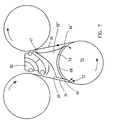
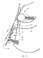
- A blowing device in a paper machine or the like, such as in a paperboard or a finishing machine, where the web (16) is conveyed over a cylinder (10, 12), such as a drying cylinder or another roll, supported by a support fabric, such as a wire (18) or the like, between the cylinder and the support fabric, and which blowing device comprises a blow box (30) or a blow box combination (30', 30") extending over the whole width of the web and being connected to means (74) generating blowing air, and which blowing device iswhereby the sealing means maintain a negative pressure in the space between the blowing device and the web, characterised in thatarranged on that side of the support fabric (18) which is away from the cylinder (10) mainly at the opening nip (22) or the like between the support fabric and the cylinder so that it extends from this nip or the like at least a short distance forward in the travel direction of the support fabric, andprovided with at least two sealing members (33, 36, 44, 46, 66), such as gap nozzles, ejecting nozzles, mechanical seals or the like being transversal regarding the travel direction of the web, which sealing members are arranged in the blowing device so thata first sealing member being a nozzle (36) is arranged in the blow box close to the support fabric, mainly at the opening nip (22) or the like between the support fabric and the cylinder for blowing air jets away from the gap (34) between the support fabric and the blowing device, anda second sealing means (33, 44, 46, 66) is arranged in the blow box close to the support fabric (18) or to the roll (14) turning the support fabric at a distance from the above mentioned opening nip or the like in the travel direction of the support fabric,in the blowing device at a short distance from the opening nip or the like there is further arranged a throttling means (50) projecting toward the support fabric, the throttling means dividing the negative pressure space formed between the first and the second sealing means ina first intensified negative pressure region (34') being limited at a location at the opening nip or the like, anda second smaller negative pressure region (34", 20').
- A blowing device according to claim 1, characterised in that the second sealing means is a nozzle (44, 46).
- A blowing device according to claim 2 in a web drying section provided with a single wire run, characterised in thatthe blowing device is a blow box (36) which is mainly arranged close to the disengaging point (40) between the drying cylinder and the wire; and thatthe second nozzle (44) of the blow box is arranged close to the closing nip between the turn roll and the wire, so that the air jets discharged from this nozzle (44) suck with an ejection effect air away from the closing nip and from the space (34") between the blow box and the wire.
- A blowing device according to claim 3, characterised in that in the blow box between the first nozzle (36) and the throttling means (50) there is arranged a suction orifice (54) which is connected to devices creating suction in order to intensify the negative pressure in the intensified negative pressure region (34').
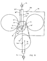
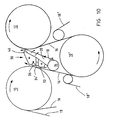
- A blowing device according to claim 2 in a web drying section provided with a single wire run, characterised in thatthe blowing device is a blow box (36) which is arranged in the pocket (20) formed between two drying cylinders (10, 12) and the turn roll (14), between on one hand the opening nip (22) between the first drying cylinder (10) and the wire (18) and on the other hand the closing nip (28) between the second drying cylinder (12) and the wire (18), and thatthe second nozzle (46) of the blow box is arranged close to the closing nip between the second drying cylinder (12) and the wire, so thatthe air jets discharged from this nozzle suck with an ejection effect air away from the pocket (20).
- A blowing device according to claim 5, characterised in that in the blow box between the first nozzle (36) and the throttling means (50) there is arranged a suction orifice (54) which is connected to devices creating suction in order to increase the negative pressure in the intensified negative pressure region (34').
- A blowing device according to claim 1, characterised in that the throttling means (50) comprises an ejecting nozzle being arranged in the blow box and projecting toward the support fabric, the ejecting nozzle being arranged to eject with the aid of air jets air away from the intensified negative pressure region (34') into the second negative pressure region (34') or completely away from the negative pressure space.
- A blowing device according to claim 7, characterised in that in the throttling means (50) there is arranged a convex surface which guides the ejecting air jets away from the intensified negative pressure region (34") utilising the Coanda effect.
- A blowing device according to claim 8, characterised in that a guide plate (68) is arranged between on one hand the throttling means (50) and on the other hand the closing nip between the turn roll and the support fabric, to prevent the air ejected away with the aid of the ejecting nozzle from reaching said closing nip.
- A blowing device according to claim 1, characterised in that the throttling means (50) comprises a mechanical sealing means, such as a means restricting the air flow, which means extends across the web and is mounted resiliently or pivotally in the blow box in order to maintain an intensified negative pressure in the intensified negative pressure region.
- A blowing device according to claim 10, characterised in that the throttling means (50) has a surface which is directed against the support fabric and which is wave-formed.
- A blowing device according to claim 1, characterised in that the first nozzle (36) and the throttling means (50) are integrated in a common structure covering the intensified negative pressure region (34"), which structure is pivotally and/or resiliently arranged at a small distance from the support fabric passing in the opening nip.
- A blowing device according to claim 1, characterised in that the throttling means is arranged to extend to a distance which is 2 to 40 mm, typically less than 20 mm, advantageously < 10 mm from the support fabric.
- A blowing device according to claim 1, characterised in that the length of the intensified negative pressure region (34') between the first nozzle and the throttling means (50) is about 50 to 500 mm, typically 100 to 200 mm, in the travel direction of the support fabric.
- A blowing device according to claim 1, characterised in thatthe first nozzle (36) is arranged at a distance of less than 300 mm, typically 40 to 150 mm, most advantageously about 70 mm from the disengaging point (40) of the support fabric, before this disengaging point regarding the travel direction of the support fabric, and thatthe throttling means (50) is arranged at a distance of about 40 to 250 mm, typically 80 to 120 mm, most advantageously about 100 mm from the disengaging point of the support fabric, after the disengaging point of the support fabric regarding the travel direction of the support fabric.
- A blowing device according to claim 1 in a web drying section provided with a single wire run, characterised in thatthe blowing device comprises a first blow box section (30') and a second box section (30") which are arranged in the pocket (20) formed between two drying cylinders (10, 12) and a turn roll (14), such as a VAC roll or other suction roll, between on one hand the opening nip (22) between the first drying cylinder and the wire and on the other hand the closing nip (28) between the second drying cylinder and the wire,the first blow box section (30') is arranged before the opening nip,the first nozzle (36) and the throttling means (50) are arranged in the first blow box section,the second box section (30") is arranged to cover at least a part of the surface bordering to the pocket of the turn roll, and thatbetween the first blow box section (30') and the second box section (30") there is formed an air discharge channel (56) for directing the air which is discharged from the intensified negative pressure region out from the negative pressure space.
- A blowing device according to claim 16, characterised in thatthe throttling means (50) comprises an ejecting nozzle provided with a convex output surface and arranged at the end of the first blow box section, the ejection nozzle being arranged to eject out air from the intensified negative pressure region with the aid of air jets, and thatthe input opening of the air discharge channel (56) is arranged close to the convex output surface of the ejecting nozzle, so that the air passing along the convex surface is guided directly to the air discharge channel due to the Coanda effect.
- A blowing device according to claim 16, characterised in that the surface (64) of the second box section (30") directed toward the turn roll is wave-shaped.
- A blowing device according to claim 16, characterised in that the second box section (30") is a blow box having a nozzle (46), which is arranged close to the closing nip of the second drying cylinder.
- A blowing device according to claim 1, characterised in that the second sealing means is a mechanical means (33, 66) restricting the air flow, and that the roll is a suction roll.
- A blowing device according to claim 1 in the drying section provided with a twin wire run, characterised in thatthe blowing device is a blow box (36) which is arranged in the pocket (20) formed between two drying cylinders (10, 12) and the turn roll (14), between on one hand the opening nip (22) between the first drying cylinder (10) and the upper wire (18) and on the other hand the closing nip (28) between the second drying cylinder (12) and the upper wire (18), and thatthe second nozzle (46) of the blow box is arranged close to the closing nip between the second drying cylinder (12) and the upper wire, so thatthe air jets discharged from this nozzle suck air away from the pocket (20) with an ejection effect.
Applications Claiming Priority (3)
| Application Number | Priority Date | Filing Date | Title |
|---|---|---|---|
| FI990370A FI110625B (en) | 1999-02-22 | 1999-02-22 | Blowing device in paper machine or equivalent |
| FI990370 | 1999-02-22 | ||
| PCT/FI2000/000130 WO2000050693A1 (en) | 1999-02-22 | 2000-02-21 | Blowing apparatus in a paper machine or the like |
Publications (2)
| Publication Number | Publication Date |
|---|---|
| EP1155189A1 EP1155189A1 (en) | 2001-11-21 |
| EP1155189B1 true EP1155189B1 (en) | 2004-06-09 |
Family
ID=8553883
Family Applications (2)
| Application Number | Title | Priority Date | Filing Date |
|---|---|---|---|
| EP00906388A Expired - Lifetime EP1194641B1 (en) | 1999-02-22 | 2000-02-21 | Method and apparatus in the drying section of a paper machine or the like |
| EP00906389A Expired - Lifetime EP1155189B1 (en) | 1999-02-22 | 2000-02-21 | Blowing apparatus in a paper machine or the like |
Family Applications Before (1)
| Application Number | Title | Priority Date | Filing Date |
|---|---|---|---|
| EP00906388A Expired - Lifetime EP1194641B1 (en) | 1999-02-22 | 2000-02-21 | Method and apparatus in the drying section of a paper machine or the like |
Country Status (16)
| Country | Link |
|---|---|
| US (2) | US6574884B1 (en) |
| EP (2) | EP1194641B1 (en) |
| JP (3) | JP3800316B2 (en) |
| KR (2) | KR100460517B1 (en) |
| CN (2) | CN1188571C (en) |
| AT (2) | ATE295913T1 (en) |
| AU (2) | AU2807500A (en) |
| CA (2) | CA2371804C (en) |
| CZ (2) | CZ20013031A3 (en) |
| DE (4) | DE60011397T2 (en) |
| DK (1) | DK1194641T3 (en) |
| ES (2) | ES2173050T3 (en) |
| FI (2) | FI110625B (en) |
| PL (2) | PL195509B1 (en) |
| PT (2) | PT1155189E (en) |
| WO (2) | WO2000050692A1 (en) |
Cited By (1)
| Publication number | Priority date | Publication date | Assignee | Title |
|---|---|---|---|---|
| EP2607548A1 (en) * | 2011-12-20 | 2013-06-26 | Metso Paper Inc. | Runnability component for the drying section of a paper machine and method for drying a paper web |
Families Citing this family (36)
| Publication number | Priority date | Publication date | Assignee | Title |
|---|---|---|---|---|
| FI110625B (en) | 1999-02-22 | 2003-02-28 | Metso Paper Inc | Blowing device in paper machine or equivalent |
| FI114935B (en) | 2000-06-09 | 2005-01-31 | Metso Paper Inc | Method and system in a paper machine or equivalent for transferring web from press portion to dryer section |
| FI111174B (en) | 2000-10-27 | 2003-06-13 | Metso Paper Inc | Method and apparatus for the tip drawing in a paper machine or corresponding drying portion |
| FI118811B (en) * | 2000-11-06 | 2008-03-31 | Metso Paper Inc | Blow drying section and drying group |
| DE10140801A1 (en) * | 2001-08-20 | 2003-03-06 | Voith Paper Patent Gmbh | Device for treating a fibrous web |
| FI111280B (en) | 2001-11-08 | 2003-06-30 | Metso Paper Inc | Blow box to control web flow |
| FI120746B (en) | 2001-12-19 | 2010-02-15 | Metso Paper Inc | Drying portion of a paper or cardboard machine |
| JP3723158B2 (en) | 2002-05-30 | 2005-12-07 | 三菱重工業株式会社 | Dryer vacuum box |
| FI115232B (en) | 2002-11-19 | 2005-03-31 | Metso Paper Inc | Sealing device against moving fabric |
| FI119152B (en) * | 2004-06-03 | 2008-08-15 | Metso Paper Inc | Procedure and arrangement in paper machine or equivalent in the vicinity of a generally supported mobile web, sealing device and paper machine |
| FI20050596A0 (en) * | 2005-06-06 | 2005-06-06 | Metso Paper Inc | Apparatus and method for sealing a pocket space existing between dryer cylinders in a paper machine or equivalent |
| US20070180729A1 (en) * | 2006-01-26 | 2007-08-09 | Girolamo Paul A | Blow box apparatus |
| US20070193057A1 (en) * | 2006-01-26 | 2007-08-23 | Girolamo Paul A | Rotatable vacuum transfer roll apparatus |
| FI119029B (en) * | 2006-01-30 | 2008-06-30 | Metso Paper Inc | Method and apparatus in the drying section of a fiber web machine such as a paper or board machine |
| FI20065061L (en) * | 2006-01-30 | 2007-07-31 | Metso Paper Inc | Method and apparatus in the drying section of a nonwoven machine, such as a paper or board machine |
| FI124219B (en) | 2007-11-14 | 2014-05-15 | Valmet Technologies Inc | Scraping apparatus for removing a threading strap from a moving surface with a fiber web machine |
| CN101910512B (en) * | 2007-12-31 | 2012-03-28 | 美卓造纸机械公司 | Operative member of a paper machine or paper board machine or finishing machine, related negative pressure device and method for saving energy |
| AT506409B1 (en) * | 2008-06-17 | 2009-09-15 | Andritz Ag Maschf | DEVICE AND METHOD FOR TRANSFERRING A MATERIAL TRACK |
| AT506408B1 (en) * | 2008-06-17 | 2009-09-15 | Andritz Ag Maschf | DEVICE AND METHOD FOR TRANSFERRING A MATERIAL TRACK |
| AT506407B1 (en) * | 2008-06-17 | 2009-09-15 | Andritz Ag Maschf | DEVICE AND METHOD FOR TRANSFERRING A MATERIAL TRACK |
| SE532624C2 (en) * | 2008-06-19 | 2010-03-09 | Andritz Technology And Asset Management Gmbh | Cooling of a cellulose pulp web |
| FI124037B (en) * | 2008-09-03 | 2014-02-14 | Ev Group Oy | Apparatus as well as a method for improving the removal of paper from a drying machine of a papermaking machine |
| FI20095042A (en) * | 2009-01-20 | 2010-07-21 | Metso Paper Inc | Method and apparatus for facilitating tip drawing on the dryer portion of a paper machine |
| CN101487198B (en) * | 2009-02-10 | 2011-07-20 | 湖南正大轻科机械有限公司 | Paper web stabilizer of high-speed paper machine |
| FI124766B (en) * | 2010-06-30 | 2015-01-15 | Valmet Technologies Inc | A method for mastering the bead of a fiber web and a drying portion of a fiber web machine |
| FI124504B (en) * | 2011-03-08 | 2014-09-30 | Valmet Technologies Inc | Runnability Component and Method for Improving the Efficiency of the Running Component of a Paper Machine |
| EP2803765A1 (en) * | 2013-05-17 | 2014-11-19 | Brunnschweiler S.A. | Method and system for the stabilization of paper applicable in paper drying machines and processes |
| US11429121B2 (en) | 2013-07-12 | 2022-08-30 | Best Technologies, Inc. | Fluid flow device with sparse data surface-fit-based remote calibration system and method |
| US10030882B2 (en) | 2013-07-12 | 2018-07-24 | Best Technologies, Inc. | Low flow fluid controller apparatus and system |
| CA3174856A1 (en) | 2013-07-12 | 2015-01-15 | John C. Karamanos | Fluid control measuring device |
| US11815923B2 (en) | 2013-07-12 | 2023-11-14 | Best Technologies, Inc. | Fluid flow device with discrete point calibration flow rate-based remote calibration system and method |
| CN103750534A (en) * | 2013-12-19 | 2014-04-30 | 云南中烟昆船瑞升科技有限公司 | Reconstituted tobacco base sheet transferring device |
| SE538854C2 (en) | 2014-01-09 | 2017-01-03 | Valmet Oy | Wheelchair for receiving and rolling up a paper web, which comes from a drying cylinder in a paper machine, to a roll, as well as a paper machine using a wheelchair |
| US10434796B2 (en) * | 2017-03-17 | 2019-10-08 | Ricoh Company, Ltd. | Dryer, printer, and liquid applicator |
| DE102019124500A1 (en) * | 2019-09-12 | 2020-09-10 | Voith Patent Gmbh | Device for drying a fibrous web |
| CN114541166B (en) * | 2022-01-29 | 2024-03-08 | 江苏理文造纸有限公司 | Carton capable of forming two-stage vacuum zone and paper machine |
Family Cites Families (14)
| Publication number | Priority date | Publication date | Assignee | Title |
|---|---|---|---|---|
| US4359827B1 (en) | 1979-11-05 | 1994-03-29 | Keith V Thomas | High speed paper drying |
| FI59637C (en) * | 1979-11-20 | 1981-09-10 | Valmet Oy | ANORDNING I TORKPARTIET AV EN PAPPERSMASKIN |
| AU592564B2 (en) * | 1986-04-08 | 1990-01-18 | Beloit Corporation | A blow box for a dryer |
| FI80491C (en) * | 1987-09-02 | 1990-06-11 | Valmet Paper Machinery Inc | FOERFARANDE OCH TORKNINGSGRUPP I MAONGCYLINDERTORKEN AV EN PAPPERSMASKIN. |
| DE3914761A1 (en) * | 1989-03-08 | 1990-11-15 | Voith Gmbh J M | GUIDE ROLLER FOR A POROUS BAND, FOR EXAMPLE FOR A DRY SCREEN OF A PAPER MACHINE |
| FI82850C (en) * | 1989-03-21 | 1991-04-25 | Valmet Paper Machinery Inc | Method and apparatus in the drying section of a coating machine or paper machine |
| DE9110134U1 (en) | 1991-08-16 | 1991-09-26 | J.M. Voith Gmbh, 7920 Heidenheim, De | |
| DE4141296A1 (en) | 1991-12-14 | 1993-06-17 | Voith Gmbh J M | Papermaking drying section - has suction box with structured sealing bar positions to detach web and carrier belt together from the drying cylinder surface |
| WO1994003675A1 (en) | 1992-07-31 | 1994-02-17 | J.M. Voith Gmbh | Assembly with a suction roller |
| US5515619A (en) | 1993-08-06 | 1996-05-14 | J.M. Voith Gmbh | Flexibly mounted sealing strips of a vacuum roll for a web dryer |
| US5535527A (en) | 1995-06-07 | 1996-07-16 | Valmet Corporation | Method and arrangement in a multi-cylinder dryer of a paper machine |
| DE29601543U1 (en) | 1996-01-30 | 1996-03-28 | Voith Sulzer Papiermasch Gmbh | Device for guiding a fibrous web in a single-tier dryer section |
| FI110625B (en) | 1999-02-22 | 2003-02-28 | Metso Paper Inc | Blowing device in paper machine or equivalent |
| FI4349U1 (en) | 1999-10-22 | 2000-02-28 | Valmet Corp | Blower sealing nozzle for use in a paper machine dryer section |
-
1999
- 1999-02-22 FI FI990370A patent/FI110625B/en not_active IP Right Cessation
- 1999-09-08 FI FI991908A patent/FI106568B/en not_active IP Right Cessation
-
2000
- 2000-02-21 AT AT00906388T patent/ATE295913T1/en active
- 2000-02-21 DE DE60011397T patent/DE60011397T2/en not_active Expired - Lifetime
- 2000-02-21 DE DE1194641T patent/DE1194641T1/en active Pending
- 2000-02-21 CN CNB008041547A patent/CN1188571C/en not_active Expired - Lifetime
- 2000-02-21 CA CA002371804A patent/CA2371804C/en not_active Expired - Lifetime
- 2000-02-21 WO PCT/FI2000/000129 patent/WO2000050692A1/en active IP Right Grant
- 2000-02-21 CA CA002362186A patent/CA2362186C/en not_active Expired - Lifetime
- 2000-02-21 AU AU28075/00A patent/AU2807500A/en not_active Abandoned
- 2000-02-21 DE DE60020238T patent/DE60020238T2/en not_active Expired - Lifetime
- 2000-02-21 AT AT00906389T patent/ATE268831T1/en active
- 2000-02-21 EP EP00906388A patent/EP1194641B1/en not_active Expired - Lifetime
- 2000-02-21 EP EP00906389A patent/EP1155189B1/en not_active Expired - Lifetime
- 2000-02-21 DE DE1155189T patent/DE1155189T1/en active Pending
- 2000-02-21 PT PT00906389T patent/PT1155189E/en unknown
- 2000-02-21 US US09/913,915 patent/US6574884B1/en not_active Expired - Lifetime
- 2000-02-21 CZ CZ20013031A patent/CZ20013031A3/en unknown
- 2000-02-21 KR KR10-2001-7010710A patent/KR100460517B1/en not_active IP Right Cessation
- 2000-02-21 US US09/913,901 patent/US6910282B1/en not_active Expired - Lifetime
- 2000-02-21 WO PCT/FI2000/000130 patent/WO2000050693A1/en active IP Right Grant
- 2000-02-21 KR KR10-2001-7010709A patent/KR100460518B1/en not_active IP Right Cessation
- 2000-02-21 DK DK00906388T patent/DK1194641T3/en active
- 2000-02-21 PL PL00364775A patent/PL195509B1/en unknown
- 2000-02-21 ES ES00906388T patent/ES2173050T3/en not_active Expired - Lifetime
- 2000-02-21 CN CN00804155A patent/CN1119454C/en not_active Expired - Lifetime
- 2000-02-21 JP JP2000601246A patent/JP3800316B2/en not_active Expired - Fee Related
- 2000-02-21 PT PT00906388T patent/PT1194641E/en unknown
- 2000-02-21 PL PL364691A patent/PL194976B1/en unknown
- 2000-02-21 AU AU28074/00A patent/AU2807400A/en not_active Abandoned
- 2000-02-21 CZ CZ20013030A patent/CZ20013030A3/en unknown
- 2000-02-21 JP JP2000601247A patent/JP3574791B2/en not_active Expired - Fee Related
- 2000-02-21 ES ES00906389T patent/ES2169711T3/en not_active Expired - Lifetime
-
2005
- 2005-04-18 JP JP2005120134A patent/JP2005248416A/en not_active Withdrawn
Cited By (1)
| Publication number | Priority date | Publication date | Assignee | Title |
|---|---|---|---|---|
| EP2607548A1 (en) * | 2011-12-20 | 2013-06-26 | Metso Paper Inc. | Runnability component for the drying section of a paper machine and method for drying a paper web |
Also Published As
Similar Documents
| Publication | Publication Date | Title |
|---|---|---|
| EP1155189B1 (en) | Blowing apparatus in a paper machine or the like | |
| US5477624A (en) | Two-wire cylinder dryer | |
| US4694587A (en) | Method and apparatus in a twin-wire cylinder drying section of a paper machine | |
| JP2851369B2 (en) | Method and apparatus for reinforcing web passing for use in the dryer section of a paper machine | |
| US5438765A (en) | Method and apparatus for eliminating the flutter of a paper web in the dryer section of a papermaking machine between two single felt configurations therein | |
| CA2736402C (en) | Runnability component for sealing of a pocket space between drying cylinders in a paper machine or similar, and method for manufacturing a runnability component | |
| JP5236744B2 (en) | Apparatus and method for controlling negative pressure in a drying section of a paper machine or the like | |
| CA2190563C (en) | Device and method to stabilize sheet between press section and dryer section of a paper-making machine | |
| WO2010084241A1 (en) | Method and arrangement for facilitating web threading in a paper machine's drying section | |
| CA2424999C (en) | Arrangement in connection with a drying cylinder and a reel-up of a paper machine | |
| US5820733A (en) | Device to stabilize sheet between press section and dryer section of a paper-making machine | |
| US6662468B2 (en) | Dryer section of a paper or board machine | |
| FI122926B (en) | Arrangement and procedure for saving energy in dryer section of paper machine or equivalent |
Legal Events
| Date | Code | Title | Description |
|---|---|---|---|
| PUAI | Public reference made under article 153(3) epc to a published international application that has entered the european phase |
Free format text: ORIGINAL CODE: 0009012 |
|
| 17P | Request for examination filed |
Effective date: 20010822 |
|
| AK | Designated contracting states |
Kind code of ref document: A1 Designated state(s): AT BE CH CY DE DK ES FI FR GB GR IE IT LI LU MC NL PT SE |
|
| AX | Request for extension of the european patent |
Free format text: AL;LT;LV;MK;RO;SI |
|
| EL | Fr: translation of claims filed | ||
| DET | De: translation of patent claims | ||
| REG | Reference to a national code |
Ref country code: ES Ref legal event code: BA2A Ref document number: 2169711 Country of ref document: ES Kind code of ref document: T1 |
|
| GRAP | Despatch of communication of intention to grant a patent |
Free format text: ORIGINAL CODE: EPIDOSNIGR1 |
|
| GRAS | Grant fee paid |
Free format text: ORIGINAL CODE: EPIDOSNIGR3 |
|
| GRAA | (expected) grant |
Free format text: ORIGINAL CODE: 0009210 |
|
| AK | Designated contracting states |
Kind code of ref document: B1 Designated state(s): AT BE CH CY DE DK ES FI FR GB GR IE IT LI LU MC NL PT SE |
|
| PG25 | Lapsed in a contracting state [announced via postgrant information from national office to epo] |
Ref country code: BE Free format text: LAPSE BECAUSE OF FAILURE TO SUBMIT A TRANSLATION OF THE DESCRIPTION OR TO PAY THE FEE WITHIN THE PRESCRIBED TIME-LIMIT Effective date: 20040609 Ref country code: LI Free format text: LAPSE BECAUSE OF FAILURE TO SUBMIT A TRANSLATION OF THE DESCRIPTION OR TO PAY THE FEE WITHIN THE PRESCRIBED TIME-LIMIT Effective date: 20040609 Ref country code: CH Free format text: LAPSE BECAUSE OF FAILURE TO SUBMIT A TRANSLATION OF THE DESCRIPTION OR TO PAY THE FEE WITHIN THE PRESCRIBED TIME-LIMIT Effective date: 20040609 Ref country code: NL Free format text: LAPSE BECAUSE OF FAILURE TO SUBMIT A TRANSLATION OF THE DESCRIPTION OR TO PAY THE FEE WITHIN THE PRESCRIBED TIME-LIMIT Effective date: 20040609 |
|
| REG | Reference to a national code |
Ref country code: GB Ref legal event code: FG4D |
|
| REG | Reference to a national code |
Ref country code: CH Ref legal event code: EP |
|
| REF | Corresponds to: |
Ref document number: 60011397 Country of ref document: DE Date of ref document: 20040715 Kind code of ref document: P |
|
| REG | Reference to a national code |
Ref country code: IE Ref legal event code: FG4D |
|
| PG25 | Lapsed in a contracting state [announced via postgrant information from national office to epo] |
Ref country code: GR Free format text: LAPSE BECAUSE OF FAILURE TO SUBMIT A TRANSLATION OF THE DESCRIPTION OR TO PAY THE FEE WITHIN THE PRESCRIBED TIME-LIMIT Effective date: 20040909 Ref country code: DK Free format text: LAPSE BECAUSE OF FAILURE TO SUBMIT A TRANSLATION OF THE DESCRIPTION OR TO PAY THE FEE WITHIN THE PRESCRIBED TIME-LIMIT Effective date: 20040909 |
|
| REG | Reference to a national code |
Ref country code: SE Ref legal event code: TRGR |
|
| REG | Reference to a national code |
Ref country code: PT Ref legal event code: SC4A Free format text: AVAILABILITY OF NATIONAL TRANSLATION Effective date: 20040820 |
|
| LTIE | Lt: invalidation of european patent or patent extension |
Effective date: 20040609 |
|
| NLV1 | Nl: lapsed or annulled due to failure to fulfill the requirements of art. 29p and 29m of the patents act | ||
| REG | Reference to a national code |
Ref country code: CH Ref legal event code: PL |
|
| REG | Reference to a national code |
Ref country code: ES Ref legal event code: FG2A Ref document number: 2169711 Country of ref document: ES Kind code of ref document: T3 |
|
| PG25 | Lapsed in a contracting state [announced via postgrant information from national office to epo] |
Ref country code: IE Free format text: LAPSE BECAUSE OF NON-PAYMENT OF DUE FEES Effective date: 20050221 Ref country code: CY Free format text: LAPSE BECAUSE OF FAILURE TO SUBMIT A TRANSLATION OF THE DESCRIPTION OR TO PAY THE FEE WITHIN THE PRESCRIBED TIME-LIMIT Effective date: 20050221 Ref country code: LU Free format text: LAPSE BECAUSE OF NON-PAYMENT OF DUE FEES Effective date: 20050221 |
|
| PG25 | Lapsed in a contracting state [announced via postgrant information from national office to epo] |
Ref country code: MC Free format text: LAPSE BECAUSE OF NON-PAYMENT OF DUE FEES Effective date: 20050228 |
|
| ET | Fr: translation filed | ||
| PLBE | No opposition filed within time limit |
Free format text: ORIGINAL CODE: 0009261 |
|
| STAA | Information on the status of an ep patent application or granted ep patent |
Free format text: STATUS: NO OPPOSITION FILED WITHIN TIME LIMIT |
|
| 26N | No opposition filed |
Effective date: 20050310 |
|
| REG | Reference to a national code |
Ref country code: IE Ref legal event code: MM4A |
|
| PGFP | Annual fee paid to national office [announced via postgrant information from national office to epo] |
Ref country code: FR Payment date: 20120227 Year of fee payment: 13 |
|
| PGFP | Annual fee paid to national office [announced via postgrant information from national office to epo] |
Ref country code: PT Payment date: 20120220 Year of fee payment: 13 |
|
| PGFP | Annual fee paid to national office [announced via postgrant information from national office to epo] |
Ref country code: SE Payment date: 20120217 Year of fee payment: 13 Ref country code: GB Payment date: 20120221 Year of fee payment: 13 |
|
| REG | Reference to a national code |
Ref country code: PT Ref legal event code: MM4A Free format text: LAPSE DUE TO NON-PAYMENT OF FEES Effective date: 20130821 |
|
| REG | Reference to a national code |
Ref country code: SE Ref legal event code: EUG |
|
| GBPC | Gb: european patent ceased through non-payment of renewal fee |
Effective date: 20130221 |
|
| PG25 | Lapsed in a contracting state [announced via postgrant information from national office to epo] |
Ref country code: PT Free format text: LAPSE BECAUSE OF NON-PAYMENT OF DUE FEES Effective date: 20130821 Ref country code: SE Free format text: LAPSE BECAUSE OF NON-PAYMENT OF DUE FEES Effective date: 20130222 |
|
| REG | Reference to a national code |
Ref country code: FR Ref legal event code: ST Effective date: 20131031 |
|
| PG25 | Lapsed in a contracting state [announced via postgrant information from national office to epo] |
Ref country code: GB Free format text: LAPSE BECAUSE OF NON-PAYMENT OF DUE FEES Effective date: 20130221 Ref country code: FR Free format text: LAPSE BECAUSE OF NON-PAYMENT OF DUE FEES Effective date: 20130228 |
|
| PGFP | Annual fee paid to national office [announced via postgrant information from national office to epo] |
Ref country code: ES Payment date: 20140226 Year of fee payment: 15 |
|
| REG | Reference to a national code |
Ref country code: ES Ref legal event code: FD2A Effective date: 20160331 |
|
| PG25 | Lapsed in a contracting state [announced via postgrant information from national office to epo] |
Ref country code: ES Free format text: LAPSE BECAUSE OF NON-PAYMENT OF DUE FEES Effective date: 20150222 |
|
| PGFP | Annual fee paid to national office [announced via postgrant information from national office to epo] |
Ref country code: IT Payment date: 20190225 Year of fee payment: 20 Ref country code: FI Payment date: 20190219 Year of fee payment: 20 Ref country code: DE Payment date: 20190219 Year of fee payment: 20 |
|
| PGFP | Annual fee paid to national office [announced via postgrant information from national office to epo] |
Ref country code: AT Payment date: 20190219 Year of fee payment: 20 |
|
| REG | Reference to a national code |
Ref country code: DE Ref legal event code: R071 Ref document number: 60011397 Country of ref document: DE |
|
| REG | Reference to a national code |
Ref country code: FI Ref legal event code: MAE |
|
| REG | Reference to a national code |
Ref country code: AT Ref legal event code: MK07 Ref document number: 268831 Country of ref document: AT Kind code of ref document: T Effective date: 20200221 |