EP1151862A2 - Druckwerk einer Rollenrotationsdruckmaschine, vorzugsweise einer Tiefdruck-Rollenrotationsdruckmaschine - Google Patents
Druckwerk einer Rollenrotationsdruckmaschine, vorzugsweise einer Tiefdruck-Rollenrotationsdruckmaschine Download PDFInfo
- Publication number
- EP1151862A2 EP1151862A2 EP01104663A EP01104663A EP1151862A2 EP 1151862 A2 EP1151862 A2 EP 1151862A2 EP 01104663 A EP01104663 A EP 01104663A EP 01104663 A EP01104663 A EP 01104663A EP 1151862 A2 EP1151862 A2 EP 1151862A2
- Authority
- EP
- European Patent Office
- Prior art keywords
- printing
- support
- printing unit
- unit according
- roller
- Prior art date
- Legal status (The legal status is an assumption and is not a legal conclusion. Google has not performed a legal analysis and makes no representation as to the accuracy of the status listed.)
- Granted
Links
Images


Classifications
-
- B—PERFORMING OPERATIONS; TRANSPORTING
- B41—PRINTING; LINING MACHINES; TYPEWRITERS; STAMPS
- B41F—PRINTING MACHINES OR PRESSES
- B41F31/00—Inking arrangements or devices
- B41F31/02—Ducts, containers, supply or metering devices
- B41F31/06—Troughs or like reservoirs with immersed or partly immersed, rollers or cylinders
- B41F31/07—Troughs or like reservoirs with immersed or partly immersed, rollers or cylinders for rotogravure
-
- B—PERFORMING OPERATIONS; TRANSPORTING
- B41—PRINTING; LINING MACHINES; TYPEWRITERS; STAMPS
- B41F—PRINTING MACHINES OR PRESSES
- B41F13/00—Common details of rotary presses or machines
- B41F13/08—Cylinders
- B41F13/20—Supports for bearings or supports for forme, offset, or impression cylinders
-
- B—PERFORMING OPERATIONS; TRANSPORTING
- B41—PRINTING; LINING MACHINES; TYPEWRITERS; STAMPS
- B41F—PRINTING MACHINES OR PRESSES
- B41F9/00—Rotary intaglio printing presses
- B41F9/06—Details
- B41F9/18—Auxiliary devices for exchanging forme cylinders
-
- B—PERFORMING OPERATIONS; TRANSPORTING
- B41—PRINTING; LINING MACHINES; TYPEWRITERS; STAMPS
- B41P—INDEXING SCHEME RELATING TO PRINTING, LINING MACHINES, TYPEWRITERS, AND TO STAMPS
- B41P2213/00—Arrangements for actuating or driving printing presses; Auxiliary devices or processes
- B41P2213/80—Means enabling or facilitating exchange of cylinders
- B41P2213/804—Means enabling or facilitating exchange of cylinders radially
Definitions
- the invention relates to a printing unit of a web-fed rotary printing press, preferably a rotogravure web press, with one in an ink tray immersing pressure roller, its shaft journal for changing the pressure roller can be supported on support devices, preferably support rollers.
- the object of the present invention is to provide a printing unit of the type specified at the outset Type to create, in which the exchange of the printing roller is easy and can be done quickly.
- each support device each arranged with a drive horizontally displaceable carrier is about the support devices between the bearings of the pressure roller and are displaceable in an extended position in which a lifting the printing roller and deploying facility is provided.
- the printing roller can thereby be moved quickly and simply change that the pressure roller to be replaced, which is on the support devices rests, through the horizontally displaceable carrier as far from the Printing unit can be moved out so that it is easily accessible and for the purpose their exchange can be deducted from a lifting facility, which in correspondingly also the insertion of the printing roller to be replaced can serve.
- the horizontally displaceable carriers are expediently displaceable in guides Racks.
- the racks can be driven by a shaft be that carries the rack and pinion.
- the device lifting and inserting the printing rollers can be and lowerable supports for the shaft journals. These can Lift and hold the platen roller from its support, lifting out the pressure roller from the supports through the usual lifting and transport devices, for example, forklifts.
- the guides and the drive for the supports are advantageously in one frame connected to the printing unit frame.
- the guides can be raised and lowered by two supports each in height are staggered.
- This embodiment of the invention makes it possible in one Pair of supports to accommodate the pressure roller to be replaced and in the other pair of pads to have the newly installed pressure roller ready, so that the exchange is carried out quickly and the replaced printing roller is removed can be while the other is brought into its operating position or has been spent.
- the ink tray to the print roller unhindered by the To be able to extend the ink tray horizontally.
- the paint pan on one in the Printing machine frame is raised and lowered tub support.
- the drive of the tub support can consist of a rack and pinion drive.
- the tub support is expediently located in a in the printing press frame the guide device can be lifted and lowered horizontally, so that the paint pan for the purpose of their exchange from the Printing unit can be moved out.
- the carrier is expediently provided with a groove or bore Provide coupling rod in the in the raised position with the Bolt or pin connected to the tub support engages.
- the lifting and lowering beams under the support or supports for the Printing rollers with a support or supports for the ink tray or ink trays are provided.
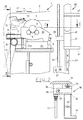
- the printing unit 1 has a printing unit frame, of which only the rear side frame 2 is visible because the front of the better clarity is removed.
- the pressure cylinder 3 via its shaft journal 4 in Usually stored in the side frames 2 of the printing unit frame.
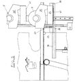
- the pressure roller 3 In the 1 and 3 apparent position is the pressure roller 3 from its bearings loosened and is supported in preparation for their replacement on the support rollers 5.
- the support rollers 5 are in support roller bearing blocks via shaft journals, not shown 6 rotatably mounted, which is attached to racks 7 on both sides of the pressure roller 3 are.
- the racks 7 are in the rear region in guides fixed to the frame or guide sleeves 8 and are supported in their front area on in Supported support rollers 9 from the frame.
- a pinion 10 mounted in the machine frame that meshes with the rack 7 in the manner shown and for example driven by a drive, not shown, via a toothed belt 11 is.
- the drive pinions 10 are mounted on a shaft 10a fixed to the frame, so that they drive the two racks 7 synchronously.
- doctor blade carrier 12 Between the side frames 2 of the printing unit frame is a usual doctor blade carrier 12 supported, the doctor blade adjustable in the usual manner on the pressure roller 3 13 wears.
- Racks 16 are vertical in lateral guides 15 of the printing unit frame slidably guided at its upper ends a frame 17 with lateral Guides 18 for a tub support horizontally displaceable in the guides 18 19 wear.
- On the tub support 19 rests the paint pan 20, which over supports lateral tub feet 21 forming sheets on the tub support 19 and is supported on it in a manner not shown.
- the racks 16 are with a drive, not shown, and a synchronous shaft 22 provided that synchronizing at their ends and with the racks 16 meshing pinions 23 carries.
- the synchronous shaft is not shown in Way stored in the printing unit frame.
- the tray support 19, which can be extended and retracted like a drawer, is in its side areas connected parallel to the tub feet 21 with web plates 25, which are rectangular cantilevered bolts 26.
- the bolts 26 engage in the grooves of U-shaped profiles 27, which connects to the inner sides of the racks 7 via connecting bolts 28 are connected so that together with the racks 7 also the tub support 19 and the ink pan 20 carried by this is moved.
- the printing roller 3 is optionally behind the printing unit frame with the side parts 2 arranged with ink pan 20 lifting and inserting device 30, whose side parts 31 rigidly with the side frames in a manner not shown 2 of the printing unit frame are connected.
- the device 30 consists of two Carriers 32, the guides 33 in the side parts 31 in the vertical direction are guided.
- To move the carrier 32 are two on the side parts 1 mounted spindles 34 are provided, which engage in spindle nuts 35, which with the carriers 32 are connected.
- To drive the spindles 34 are with drives provided gear provided, the gear 36 by a synchronous shaft 37 are connected to each other in the usual way.
- the carrier 32 is at a vertical distance from one another, each with two supports 40 for the shaft journals 4 of the pressure rollers 3 and below them with conditions 41 to set the tub feet 21.
- the ink tray 20 itself is connected to the tray feet 21 in a conventional manner, the rear area of the ink tray via an interposed plate 21a is supported on the tub feet 21.
Landscapes
- Engineering & Computer Science (AREA)
- Mechanical Engineering (AREA)
- Inking, Control Or Cleaning Of Printing Machines (AREA)
- Rotary Presses (AREA)
- Replacement Of Web Rolls (AREA)
Abstract
Description
- Fig. 1
- eine Seitenansicht eines Druckwerks mit entferntem vorderen Seitengestell, bei dem die auszutauschende Druckwalze auf Stützrollen ruht, und mit einer die Druckwalze aushebenden und einsetzenden Einrichtung in schematischer Darstellung,
- Fig. 2
- eine Draufsicht auf die die Druckwalzen aushebende und einsetzende Einrichtung nach Fig. 1,
- Fig. 3
- eine Ansicht des Druckwerks in Richtung des Pfeils A in Fig. 1,
- Fig. 4
- eine der Fig. 1 entsprechende Darstellung, in der die Farbwanne abgesenkt und die auszutauschende Druckwalze auf den synchron heb- und absenkbaren Auflagern der die Druckwalze aushebenden und einsetzenden Einrichtung ruht, und
- Fig. 5
- eine der Fig. 1 entsprechende Darstellung, in der die auszutauschende Druckwalze mit zugehöriger Farbwanne von der die Druckwalzen aushebenden und einsetzenden Einrichtung aufgenommen ist.
Claims (12)
- Druckwerk (1) einer Rollenrotationsdruckmaschine, vorzugsweise einer Tiefdruck-Rollenrotationsdruckmaschine, mit einer in eine Farbwanne (20) eintauchenden Druckwalze (3), deren Wellenzapfen (4) zum Wechseln der Druckwalze (3) auf Stützeinrichtungen, vorzugsweise Stützrollen (5), abstützbar sind,
dadurch gekennzeichnet, daß jede Stützeinrichtung (5) auf je einem mit einem Antrieb (10, 11) versehenen, horizontal verschieblichen Träger (7) angeordnet ist, über die die Stützeinrichtungen (5) zwischen den Lagern der Druckwalze (3) und einer ausgefahrenen Stellung verschieblich sind, in der eine die Druckwalze (3) aushebende und einsetzende Einrichtung (30) vorgesehen ist. - Druckwerk nach Anspruch 1, dadurch gekennzeichnet, daß die Träger in Führungen (8, 9) verschiebliche Zahnstangen (7) sind.
- Druckwerk nach Anspruch 2, dadurch gekennzeichnet, daß die Zahnstangen (7) von einer Ritzel (10) tragenden Welle (10a) angetrieben sind.
- Druckwerk nach einem der Ansprüche 1 bis 3, dadurch gekennzeichnet, daß die die Druckwalzen (3) aushebende und einsetzende Einrichtung (30) aus synchron heb- und absenkbaren Auflagern (40) für die Wellenzapfen (4) der Druckwalze (3) bestehen.
- Druckwerk nach einem der Ansprüche 1 bis 4, dadurch gekennzeichnet, daß die Führungen (33) und der Antrieb für die Auflager (40) in einem mit dem Druckwerksgestell (2) verbundenen Gestell (31) angeordnet sind.
- Druckwerk nach einem der Ansprüche 1 bis 5, dadurch gekennzeichnet, daß in zwei in den Führungen (33) heb- und absenkbaren Trägern (32) je zwei Auflager (40) der Höhe nach versetzt angeordnet sind.
- Druckwerk nach einem der Ansprüche 1 bis 6, dadurch gekennzeichnet, daß die Farbwanne (20) auf einem in dem Druckmaschinengestell (2) heb- und absenkbaren Wannenträger (19) gehaltert ist.
- Druckwerk nach Anspruch 7, dadurch gekennzeichnet, daß der Antrieb des Wannenträgers (19) aus einem Ritzel-Zahnstangen-Trieb (16) besteht.
- Druckwerk nach einem der Ansprüche 1 bis 8, dadurch gekennzeichnet, daß der Wannenträger (19) in einer mit dem Druckmaschinengestell (2) heb- und absenkbaren Führungseinrichtung (17, 18) horizontal verschieblich gehaltert ist.
- Druckwerk nach einem der Ansprüche 1 bis 9, dadurch gekennzeichnet, daß der Wannenträger 19 in seiner angehobenen Stellung mit dem horizontal verschieblichen Träger (7) kuppelbar ist, so daß er zusammen mit der Druckwalze (3) aus- und einfahrbar ist.
- Druckwerk nach einem der Ansprüche 1 bis 10, dadurch gekennzeichnet, daß der Träger (7) mit einer mit einer Nut oder Bohrung versehenen Kupplungsstange (27, 28) versehen ist, in die in der angehobenen Stellung ein mit dem Wannenträger (19) verbundener Bolzen (25) oder Zapfen greift.
- Druckwerk nach einem der Ansprüche 1 bis 12, dadurch gekennzeichnet, daß der heb- und absenkbare Träger (32) unter dem Auflager (40) oder den Auflagern (40) für die Druckwalzen (3) mit einer Auflage (41) oder Auflagen (41) für die Farbwanne oder die Farbwannen (20) versehen ist.
Applications Claiming Priority (2)
| Application Number | Priority Date | Filing Date | Title |
|---|---|---|---|
| DE10021398A DE10021398B4 (de) | 2000-05-03 | 2000-05-03 | Druckwerk einer Tiefdruck-Rollenrotationsdruckmaschine |
| DE10021398 | 2000-05-03 |
Publications (3)
| Publication Number | Publication Date |
|---|---|
| EP1151862A2 true EP1151862A2 (de) | 2001-11-07 |
| EP1151862A3 EP1151862A3 (de) | 2003-09-03 |
| EP1151862B1 EP1151862B1 (de) | 2007-12-05 |
Family
ID=7640561
Family Applications (1)
| Application Number | Title | Priority Date | Filing Date |
|---|---|---|---|
| EP01104663A Expired - Lifetime EP1151862B1 (de) | 2000-05-03 | 2001-02-24 | Druckwerk einer Rollenrotationsdruckmaschine, vorzugsweise einer Tiefdruck-Rollenrotationsdruckmaschine |
Country Status (4)
| Country | Link |
|---|---|
| US (1) | US6543357B2 (de) |
| EP (1) | EP1151862B1 (de) |
| DE (2) | DE10021398B4 (de) |
| ES (1) | ES2293939T3 (de) |
Cited By (5)
| Publication number | Priority date | Publication date | Assignee | Title |
|---|---|---|---|---|
| CN100564035C (zh) * | 2004-02-27 | 2009-12-02 | 米勒.马蒂尼控股公司 | 在胶印印刷中用于建立不同的印刷规格长度的装置 |
| WO2009144016A1 (de) * | 2008-05-29 | 2009-12-03 | Windmöller & Hölscher Kg | Druckmaschine mit mehreren farbwerken |
| WO2016189433A1 (en) * | 2015-05-22 | 2016-12-01 | Bobst Firenze S.R.L. | Improved machine for indirect ink-jet printing |
| US11390067B2 (en) * | 2017-04-07 | 2022-07-19 | Bobst Firenze S.R.L. | Printing unit with interchangeable printing sleeve |
| CN117916092A (zh) * | 2022-01-17 | 2024-04-19 | 柯尼格及包尔公开股份有限公司 | 具有用于更换冲裁滚筒的装置的冲裁总成以及用于更换冲裁滚筒的方法 |
Families Citing this family (11)
| Publication number | Priority date | Publication date | Assignee | Title |
|---|---|---|---|---|
| NL1026736C2 (nl) * | 2004-07-28 | 2006-01-31 | Stork Prints Bv | Drukcilinderondersteuningseenheid, positioneerelement, drukcilinder voorzien van positioneerelement, drukmachine voorzien van drukcilinderondersteuningseenheid, en gebruik hiervan. |
| DE102006041314B4 (de) * | 2006-09-01 | 2008-10-02 | Windmöller & Hölscher Kg | Druckwerk einer Tiefdruckmaschine |
| DE102008025998B4 (de) | 2008-05-29 | 2014-11-06 | Windmöller & Hölscher Kg | Vorrichtung und ein Verfahren zum Ankoppeln einer Farbübertragungswalze |
| DE102011083151B4 (de) | 2011-09-21 | 2017-08-17 | Koenig & Bauer Ag | Rotationsdruckmaschine und ein Verfahren zum Austausch zumindest eines ersten Zylinders einer Rotationsdruckmaschine |
| CN104015469A (zh) * | 2014-05-27 | 2014-09-03 | 渭南三立印刷机械有限公司 | 一种凹印机双压辊快速更换装置 |
| CN109252382B (zh) * | 2018-09-17 | 2020-12-15 | 嘉善龙翔人造毛绒有限公司 | 一种毛皮的一体化处理装置及处理方法 |
| CN113459647B (zh) * | 2021-04-20 | 2023-12-22 | 利和纸品(嘉善)有限公司 | 一种包装纸箱双面印刷装置 |
| WO2023099552A1 (de) * | 2021-12-01 | 2023-06-08 | Koenig & Bauer Ag | Stanzaggregat mit einer vorrichtung zum wechseln eines stanzzylinders und verfahren zum wechseln eines stanzzylinders |
| EP4370340B1 (de) * | 2021-12-01 | 2025-04-16 | Koenig & Bauer AG | Stanzaggregat mit einer vorrichtung zum wechseln eines stanzzylinders und verfahren zum wechseln eines stanzzylinders |
| US20240261996A1 (en) * | 2022-01-17 | 2024-08-08 | Koenig & Bauer Ag | Die-cutting unit comprising a device for changing a die-cutting cylinder and method for changing a die-cutting cylinder |
| WO2023134919A1 (de) * | 2022-01-17 | 2023-07-20 | Koenig & Bauer Ag | Stanzaggregat, bearbeitungsmaschine aufweisend ein stanzaggregat und verfahren zum verstellen einer transporteinrichtung eines stanzaggregats |
Family Cites Families (8)
| Publication number | Priority date | Publication date | Assignee | Title |
|---|---|---|---|---|
| DE642250C (de) * | 1935-05-23 | 1937-02-27 | Dresden Leipziger Schnellpress | Tiefdruckmaschine |
| GB708272A (en) * | 1951-06-04 | 1954-05-05 | Timsons Ltd | Means for facilitating the insertion and location of liquid supply troughs into machines |
| US3589287A (en) * | 1968-05-20 | 1971-06-29 | Wood Industries Inc | Rotogravure ink fountain with cover-lifting system |
| US3610144A (en) * | 1969-10-29 | 1971-10-05 | Wood Industries Inc | Design-cylinder-loading mechanism |
| DD123910A3 (de) * | 1975-09-05 | 1977-01-26 | ||
| JPS60244556A (ja) * | 1984-05-17 | 1985-12-04 | Rengo Co Ltd | 多色刷輪転印刷機の版胴交換装置 |
| DE4340128C2 (de) * | 1993-11-25 | 1996-07-25 | Koenig & Bauer Albert Ag | Tiefdruckfarbwerk |
| EP0980311B1 (de) * | 1997-05-05 | 2001-11-07 | Koenig & Bauer Aktiengesellschaft | Farbwerk zum einfärben eines formzylinders einer tiefdruckmaschine |
-
2000
- 2000-05-03 DE DE10021398A patent/DE10021398B4/de not_active Expired - Fee Related
-
2001
- 2001-02-24 DE DE50113337T patent/DE50113337D1/de not_active Expired - Lifetime
- 2001-02-24 ES ES01104663T patent/ES2293939T3/es not_active Expired - Lifetime
- 2001-02-24 EP EP01104663A patent/EP1151862B1/de not_active Expired - Lifetime
- 2001-04-24 US US09/840,081 patent/US6543357B2/en not_active Expired - Fee Related
Cited By (9)
| Publication number | Priority date | Publication date | Assignee | Title |
|---|---|---|---|---|
| CN100564035C (zh) * | 2004-02-27 | 2009-12-02 | 米勒.马蒂尼控股公司 | 在胶印印刷中用于建立不同的印刷规格长度的装置 |
| WO2009144016A1 (de) * | 2008-05-29 | 2009-12-03 | Windmöller & Hölscher Kg | Druckmaschine mit mehreren farbwerken |
| US8931409B2 (en) | 2008-05-29 | 2015-01-13 | Windmoeller & Hoelscher Kg | Printing press with multiple inking units |
| WO2016189433A1 (en) * | 2015-05-22 | 2016-12-01 | Bobst Firenze S.R.L. | Improved machine for indirect ink-jet printing |
| CN107645991A (zh) * | 2015-05-22 | 2018-01-30 | 博斯特佛罗伦萨有限公司 | 改进的间接喷墨印刷机 |
| US10207493B2 (en) | 2015-05-22 | 2019-02-19 | Bobst Firenze S.R.L. | Machine for indirect ink-jet printing |
| CN107645991B (zh) * | 2015-05-22 | 2019-06-21 | 博斯特佛罗伦萨有限公司 | 改进的间接喷墨印刷机 |
| US11390067B2 (en) * | 2017-04-07 | 2022-07-19 | Bobst Firenze S.R.L. | Printing unit with interchangeable printing sleeve |
| CN117916092A (zh) * | 2022-01-17 | 2024-04-19 | 柯尼格及包尔公开股份有限公司 | 具有用于更换冲裁滚筒的装置的冲裁总成以及用于更换冲裁滚筒的方法 |
Also Published As
| Publication number | Publication date |
|---|---|
| DE10021398B4 (de) | 2004-07-29 |
| EP1151862B1 (de) | 2007-12-05 |
| DE10021398A1 (de) | 2001-11-08 |
| ES2293939T3 (es) | 2008-04-01 |
| US6543357B2 (en) | 2003-04-08 |
| US20010037739A1 (en) | 2001-11-08 |
| DE50113337D1 (de) | 2008-01-17 |
| EP1151862A3 (de) | 2003-09-03 |
Similar Documents
| Publication | Publication Date | Title |
|---|---|---|
| DE4413807C1 (de) | Vorrichtung zum Wechseln der Zylinder an einer Druckmaschine | |
| EP0749369B1 (de) | Druckwerk für eine mehrfarbenrollenrotationsdruckmaschine | |
| EP1151862B1 (de) | Druckwerk einer Rollenrotationsdruckmaschine, vorzugsweise einer Tiefdruck-Rollenrotationsdruckmaschine | |
| EP0745031B1 (de) | Druckwerk für eine mehrfarbenrollenrotationsdruckmaschine | |
| DE3123933C2 (de) | Walzenwechsel-Vorrichtung für ein Sechswalzen-Hochgerüst | |
| DE3316663C2 (de) | Anordnung zum Austausch von Zylindern in einer Druckmaschine | |
| DE69400025T2 (de) | Druckmaschine mit mindestens einem Zylinder mit doppeltem Verfahrweg. | |
| DE10261999B4 (de) | Druckmaschine mit Trittblech zum Erreichen der oberen Farbwerke | |
| CH652652A5 (de) | Einrichtung zum bearbeiten einer materialbahn. | |
| DE102013223252B4 (de) | Maschinelle Werkstück-Transfervorrichtung sowie maschinelle Entladevorrichtung und maschinelle Anordnung zum Bearbeiten von Werkstücken mit einer derartigen Werkstück-Transfervorrichtung | |
| DE3230833C2 (de) | Vorrichtung mit mehreren Arbeitsstationen zum Bedrucken, Ausstanzen bzw. Zuschneiden von Kartonzuschnitten | |
| DE3905073A1 (de) | Umsetzeinrichtung in einer transferpresse o. dgl. umformmaschine | |
| DE69710929T2 (de) | Druckgruppe für rotationstiefdruckmaschine | |
| DE2139834C2 (de) | Von Tiefdruck auf Flexodruck und umgekehrt umrüstbares Druckwerk für Druckmaschinen | |
| DE10209536B4 (de) | Druckmaschine, vorzugsweise Flexodruckmaschine | |
| DE3930636A1 (de) | Wagen zum tragen des druckerwerkes fuer druckstationen in rotationsdruckmaschinen | |
| DE2932115C2 (de) | Richtmaschine | |
| DE4420771C2 (de) | Verfahren und Einrichtungen zum automatischen Auswechseln des Druckzylinders in einer Rotationsdruckmaschine | |
| DE2949957C2 (de) | Druckeinheit für eine Rollen-Rotations-Offsetdruckmaschine | |
| EP0114174A1 (de) | Presse zur Rahmenherstellung | |
| DE20221164U1 (de) | Druckmaschine, vorzugsweise Flexodruckmaschine | |
| EP1558409B1 (de) | Walzwerk mit supportplatten | |
| DE612707C (de) | Stapelwechselvorrichtung fuer Bogenanleger | |
| DE8510718U1 (de) | Vorrichtung zum leichteren Einsetzen und Herausnehmen der Walze bei Umkehr-Tiefdruckmaschinen | |
| DE2049961A1 (de) | Walzenwechselvorrichtung eines Walzgerüstes |
Legal Events
| Date | Code | Title | Description |
|---|---|---|---|
| PUAI | Public reference made under article 153(3) epc to a published international application that has entered the european phase |
Free format text: ORIGINAL CODE: 0009012 |
|
| AK | Designated contracting states |
Kind code of ref document: A2 Designated state(s): AT BE CH CY DE DK ES FI FR GB GR IE IT LI LU MC NL PT SE TR |
|
| AX | Request for extension of the european patent |
Free format text: AL;LT;LV;MK;RO;SI |
|
| PUAL | Search report despatched |
Free format text: ORIGINAL CODE: 0009013 |
|
| AK | Designated contracting states |
Kind code of ref document: A3 Designated state(s): AT BE CH CY DE DK ES FI FR GB GR IE IT LI LU MC NL PT SE TR |
|
| AX | Request for extension of the european patent |
Extension state: AL LT LV MK RO SI |
|
| RIC1 | Information provided on ipc code assigned before grant |
Ipc: 7B 41F 9/18 B Ipc: 7B 41F 9/00 A Ipc: 7B 41F 31/07 B |
|
| 17P | Request for examination filed |
Effective date: 20040303 |
|
| AKX | Designation fees paid |
Designated state(s): DE ES FR GB IT |
|
| GRAP | Despatch of communication of intention to grant a patent |
Free format text: ORIGINAL CODE: EPIDOSNIGR1 |
|
| GRAS | Grant fee paid |
Free format text: ORIGINAL CODE: EPIDOSNIGR3 |
|
| GRAA | (expected) grant |
Free format text: ORIGINAL CODE: 0009210 |
|
| AK | Designated contracting states |
Kind code of ref document: B1 Designated state(s): DE ES FR GB IT |
|
| REG | Reference to a national code |
Ref country code: GB Ref legal event code: FG4D Free format text: NOT ENGLISH |
|
| REF | Corresponds to: |
Ref document number: 50113337 Country of ref document: DE Date of ref document: 20080117 Kind code of ref document: P |
|
| REG | Reference to a national code |
Ref country code: ES Ref legal event code: FG2A Ref document number: 2293939 Country of ref document: ES Kind code of ref document: T3 |
|
| ET | Fr: translation filed | ||
| GBV | Gb: ep patent (uk) treated as always having been void in accordance with gb section 77(7)/1977 [no translation filed] | ||
| PLBE | No opposition filed within time limit |
Free format text: ORIGINAL CODE: 0009261 |
|
| STAA | Information on the status of an ep patent application or granted ep patent |
Free format text: STATUS: NO OPPOSITION FILED WITHIN TIME LIMIT |
|
| 26N | No opposition filed |
Effective date: 20080908 |
|
| PG25 | Lapsed in a contracting state [announced via postgrant information from national office to epo] |
Ref country code: GB Free format text: LAPSE BECAUSE OF FAILURE TO SUBMIT A TRANSLATION OF THE DESCRIPTION OR TO PAY THE FEE WITHIN THE PRESCRIBED TIME-LIMIT Effective date: 20071205 |
|
| PGFP | Annual fee paid to national office [announced via postgrant information from national office to epo] |
Ref country code: ES Payment date: 20100312 Year of fee payment: 10 |
|
| PGFP | Annual fee paid to national office [announced via postgrant information from national office to epo] |
Ref country code: FR Payment date: 20100223 Year of fee payment: 10 |
|
| REG | Reference to a national code |
Ref country code: FR Ref legal event code: ST Effective date: 20111102 |
|
| PG25 | Lapsed in a contracting state [announced via postgrant information from national office to epo] |
Ref country code: FR Free format text: LAPSE BECAUSE OF NON-PAYMENT OF DUE FEES Effective date: 20110228 |
|
| REG | Reference to a national code |
Ref country code: ES Ref legal event code: FD2A Effective date: 20120411 |
|
| PG25 | Lapsed in a contracting state [announced via postgrant information from national office to epo] |
Ref country code: ES Free format text: LAPSE BECAUSE OF NON-PAYMENT OF DUE FEES Effective date: 20110225 |
|
| PGFP | Annual fee paid to national office [announced via postgrant information from national office to epo] |
Ref country code: DE Payment date: 20140228 Year of fee payment: 14 |
|
| PGFP | Annual fee paid to national office [announced via postgrant information from national office to epo] |
Ref country code: IT Payment date: 20140218 Year of fee payment: 14 |
|
| REG | Reference to a national code |
Ref country code: DE Ref legal event code: R119 Ref document number: 50113337 Country of ref document: DE |
|
| PG25 | Lapsed in a contracting state [announced via postgrant information from national office to epo] |
Ref country code: IT Free format text: LAPSE BECAUSE OF NON-PAYMENT OF DUE FEES Effective date: 20150224 |
|
| PG25 | Lapsed in a contracting state [announced via postgrant information from national office to epo] |
Ref country code: DE Free format text: LAPSE BECAUSE OF NON-PAYMENT OF DUE FEES Effective date: 20150901 |