EP1151697A1 - Verstellvorrichtung zur Neigungsverstellung der Frontblende einer Schublade - Google Patents
Verstellvorrichtung zur Neigungsverstellung der Frontblende einer Schublade Download PDFInfo
- Publication number
- EP1151697A1 EP1151697A1 EP01110632A EP01110632A EP1151697A1 EP 1151697 A1 EP1151697 A1 EP 1151697A1 EP 01110632 A EP01110632 A EP 01110632A EP 01110632 A EP01110632 A EP 01110632A EP 1151697 A1 EP1151697 A1 EP 1151697A1
- Authority
- EP
- European Patent Office
- Prior art keywords
- adjusting
- housing
- adjusting device
- frame
- front panel
- Prior art date
- Legal status (The legal status is an assumption and is not a legal conclusion. Google has not performed a legal analysis and makes no representation as to the accuracy of the status listed.)
- Granted
Links
Images



Classifications
-
- A—HUMAN NECESSITIES
- A47—FURNITURE; DOMESTIC ARTICLES OR APPLIANCES; COFFEE MILLS; SPICE MILLS; SUCTION CLEANERS IN GENERAL
- A47B—TABLES; DESKS; OFFICE FURNITURE; CABINETS; DRAWERS; GENERAL DETAILS OF FURNITURE
- A47B88/00—Drawers for tables, cabinets or like furniture; Guides for drawers
- A47B88/90—Constructional details of drawers
- A47B88/944—Drawers characterised by the front panel
- A47B88/95—Drawers characterised by the front panel characterised by connection means for the front panel
- A47B88/956—Drawers characterised by the front panel characterised by connection means for the front panel for enabling adjustment of the front panel
-
- A—HUMAN NECESSITIES
- A47—FURNITURE; DOMESTIC ARTICLES OR APPLIANCES; COFFEE MILLS; SPICE MILLS; SUCTION CLEANERS IN GENERAL
- A47B—TABLES; DESKS; OFFICE FURNITURE; CABINETS; DRAWERS; GENERAL DETAILS OF FURNITURE
- A47B88/00—Drawers for tables, cabinets or like furniture; Guides for drawers
- A47B88/90—Constructional details of drawers
- A47B88/919—Accessories or additional elements for drawers, e.g. drawer lighting
- A47B88/925—Additional side walls mountable on existing side walls
Definitions
- the invention relates to an adjustment device for adjusting the inclination Front panel of a drawer, especially for drawers with Drawer frames and frame attachments placed on them.
- Adjustments for the inclination of the front panel of a drawer are already known from the prior art.
- DE 43 35 393 A1 discloses an adjustment device for the front panel especially of high drawers, with the front panel in the lower Area is in turn firmly connected to the drawer frame and in the upper Area an adjusting device in the form of a knurled nut is provided an inclination adjustment of the front panel allowed.
- a housing is provided, which is placed on the drawer frame and can be detached with suitable means using the front panel and the frame attachment is connected, adjusting means being present in the housing, the one mechanical adjustment of the front panel in relation to the drawer frame or allow the frame attachment.
- the housing is preferred for easier assembly of the adjustment device formed in two parts and has means for connecting both housing parts.
- the housing is in a preferred embodiment in the lower area on a channel. In this Channel, the upper area of the drawer frame is received.
- the housing advantageously has a lateral slot for receiving the Front of the frame attachment.
- the housing is thus between Drawer frame, face of the frame attachment and front panel arranged and is one compared to the drawer end frame and the frame attachment certain adjustment path slidable.
- a first and a second are in the housing adjusting means provided with a thread or a toothing, which are mounted in molded bearing arrangements in the housing.
- a slide is arranged in the housing, which is guided in sliding guides and is stored.
- the slide has a shoulder with a toothing which meshes with the thread / the toothing of the first adjusting means. By actuating the adjusting means, the slide can be moved along the slide guides.
- the slide also has a coupling finger which engages in an opening of a coupling dowel which is fixedly connected to the front panel.
- a driver For the inclination adjustment of the front panel there is one in one in the housing Bearing ring rotatably mounted adjusting lever arranged a driver has, which engages in a bore of the frame attachment.
- the Adjustment lever on a toothing, which with the thread / the toothing of the combs second adjusting means and thus allows pivoting of the adjusting lever. Swiveling the adjustment lever has a displacement of the housing compared to the frame attachment, which is an inclination adjustment of the fixed connected to the front panel.
- the toothing is formed on an outer edge of the adjusting lever or as an internal toothing within an elongated hole provided in the adjusting lever.
- the first and second adjustment means can be threaded adjustment screws or adjustment pinions.
- the housing can have an upwardly openable lid which is arranged such that he allows access to the adjustment screws in the open position and this in Covers the closed position.
- the adjustment device preferably acts on the upper area of the Front panel.
- a drawer frame Pick-up device using a front attachment with the front panel is connectable.
- the lower front attachment allows the front panel to be adjusted within their level, i.e. to the left, right, up and down, whereas the adjustment device according to the invention an adjustment of the front panel vertically allowed to their level.
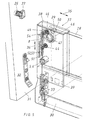
- Figure 1 shows a section of a drawer, which a left and a right Drawer frame 30 and one connected to the drawer frames Front panel 31 has.
- the drawer frame 30 has a receiving device 33 for the drawer frame a front attachment 32 fastened to the front panel 31.
- This Fastening device 32, 33 also allows adjustment of the Front panel 31 opposite the drawer frame 30 in the plane of the front panel 31, i.e. in the left, right, up and down directions.
- Frame attachment 28 attached, which - like the drawer frame 30 - the drawer rear wall (not shown) is attached.
- a frame attachment 28 is provided according to the invention, which is arranged in a housing 1.
- FIG. 1 there is the housing 1 of two housing parts 2, 3, which can be connected together.
- the Housing 1 is between the upper edge of the drawer frame 30, the front of the Frame attachment 28 and the inner surface of the front panel 31 arranged.
- the interconnected housing parts 2, 3 form an open downward Channel out, so that the housing 1 positively on the upper edge of the Drawer frame 30 can be placed.
- the housing 1 forms a lateral slot in which the end face of the frame attachment 28th is recorded.
- the other end of the housing is wide by means of a Coupling device described below with the inside of the front panel 31st connected.
- the one housing part 2 has a Locking sleeve 5, which is provided with one on the other housing part 3 Locking ring 6 cooperates, whereby the two housing parts 2, 3 together can be connected.
- each housing part 2, 3 has bearing arrangements 9 and 10, respectively when the housing 1 is assembled for storing adjusting screws 16, 19 serve.
- the adjusting screws 16, 19 have an annular groove 17, which of the upper bearing assembly 9, 10 is included, such as a journal 18 which is stored in the lower bearing arrangements 9, 10. Between the annular groove 17 and the bearing pin 18 are the adjusting screws 16, 19 with a thread Mistake.
- the slide 20 has guide rails 21, which run in the respective slide guides 7, 8.
- the slide 20 has a clutch finger 24 on, which is provided with a slope 25. This clutch finger 24 cooperates a coupling plug 26 together, which is fixed in the front panel 31st is anchored.
- the coupling plug 26 has a head 27 which is hollow on the inside is formed, and allows the engagement of the clutch finger 24.
- the adjusting screw 19 is an in within the housing 1 a bearing ring 15 rotatably mounted adjusting lever 11, the Adjusting screw 19 facing end face has a toothing 14.
- the adjusting lever 11 On the opposite side, the adjusting lever 11 has a driver 13, the engages in a bore 29 of the frame attachment 28.
- the front panel 31 is already with the front attachment 32 and Coupling dowel 2 provided, the front attachment 32 in the Recording device 33 of the frame 30 can be used, so that the Front panel 31 on the face of the frame 30 and the corresponding face of the housing 1 abuts.
- the head 27 of the coupling plug 26 protrudes above the Slider 20 into the housing 1.
- the housing 1 has a lid 4 which can be opened upwards and which provides access on the adjusting screws 16, 19 by means of a screwdriver or other tools allowed.
- the adjusting screws 16, 19 are rotatable in the Bearing arrangements 9, 10 stored.
- the thread of the adjusting screw 16 meshes with the toothing 23 of the slide 20, which acts as a clutch slide. in the The initial state is the slide 20 in its lowest position, i.e. the Clutch finger 24 is not in engagement with the head 27 of the Coupling dowel 26.
- the slide can 20 are moved upwards in its guide via the threaded toothed drive, the coupling finger 24 in the direction of the head 27 of the Coupling dowel 26 moves.
- the adjusting screw 16 is turned until the coupling finger 24 into the cavity of the head 27 of the coupling dowel penetrates. Penetration is facilitated by the clutch finger 24 has a slope 25. The clutch finger 24 penetrates the head 27 of the Coupling dowel 26, while the front panel 31 closely to the front of the Housing 1 is pulled so that the housing 1 firmly with the front panel 31st connected is.
- the second adjusting screw 19 By means of the second adjusting screw 19, the thread of which with the toothing 14 of the adjusting lever 11 combs, the position of the adjusting lever 11 and thus the position of the entire housing 1 relative to the frame attachment 28 or the Set frame 30.
- the adjusting lever 11 moves due to the toothed gear Arrow direction 34 up or down, since the adjusting lever 11 is rotatable in Bearing ring 15 is mounted. Due to this rotary movement of the adjusting lever 11 the driver 13 moves, which is approximately opposite the toothing 14 is arranged in the direction of arrow 35 forward or backward parallel to Longitudinal extension of the frame attachment 28.
- the attachment of the lower portion of the front panel 31 to the Drawer frame 30 is to some extent elastic, so that a Tilt adjustment of the front panel 31 within a certain tolerance range is possible. Because both the frame 30 and the housing are firmly attached to the inner wall the front panel 31 rests, results from an inclination adjustment in Arrow direction 35 no undesirable gap between the front panel 31 and the front the frame or the housing 1. There is only a displacement of the Housing 1 on the frame 30 or opposite the frame attachment 28, the End face yes is included within the housing, so the displacement is not visible from the outside. Once the setting has been made, cover 4 can be used again be closed and the setting process is completed.
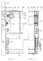
- FIG. 2 in particular shows the interaction between Adjustment screw 16 and slide 20 which is movable in the direction of arrow 36 and that Interaction between adjusting screw 19 and adjusting lever 11, which in Arrow direction 34 is pivotable, which is a displacement of the housing 1st compared to the frame attachment 28 in the direction of arrow 35.
- FIGS. 5 to 8 Another exemplary embodiment of the invention is shown in FIGS. 5 to 8 shown.
- the structure and operation of the adjustment device corresponds essentially that of the first embodiment.
- the housing 37 is formed in two parts and consists of the two Housing parts 38, 39.
- the two housing parts are 5 in through the locking sleeve Connection held together with the locking ring 6.
- the housing half 38 has two bores 40, 41 on the one hand as a bearing for two adjusting pinions 44, 45 serve and on the other hand allow access to the adjustment pinions 44, 45.
- the other housing part 39 carries two counter bearings 42, 43 for the adjusting pinions 44, 45.
- the first adjustment pinion 44 interacts with the slide 51, which is in two Slideways 7, 8 is slidably mounted.
- the slide 51 has an approach 52 with a toothing 53, which with the toothing of the assigned pinion 44 combs.
- the coupling finger 54 is located in the upper area of the slide which is bevelled upwards by a slope 55.
- An adjusting lever 46 is rotatably mounted in a bearing ring 15 and has one Elongated hole 48, one long side of which is provided with an internal toothing 49 is which meshes with the teeth of the second adjustment pinion 45, which Adjusting pinion is passed through the slot 48.
- the operation of the adjusting device in the second embodiment is almost identical to the operation of the first embodiment.
- the slider 51 cooperating pinion 44 By means of the with the slider 51 cooperating pinion 44, the slider in be moved in the vertical direction 36 so that its clutch finger 54 in the Cavity of the head 27 of the coupling plug 26 are engaged can, as shown in Figures 6 and 7.
- the adjusting pinion 45 actuates the adjusting lever 46, in that the toothing of the adjustment pinion 45 engages in the internal toothing 49 of the adjustment lever 46, the adjusting lever 46 being pivoted up or down in the direction of the arrow 34 can be.
- This causes a horizontal movement in the direction of arrow 35 of the Driver 50, which is in the bore 29 of the fixed Frame attachment 28 supports and thereby the housing 37 in the direction 35 shifts.
Landscapes
- Drawers Of Furniture (AREA)
Abstract
Description
Der Schieber weist ferner einen Kupplungsfinger auf, der in eine Öffnung eines fest mit der Frontblende verbundenen Kupplungsdübels eingreift.
Wie bereits erwähnt können das erste und zweite Verstellmittel mit Gewinden versehene Verstellschrauben oder aber Verstellritzel sein.
- Figur 1:
- Eine erste Ausführungsform der Verstellvorrichtung in einer perspektivischen Ansicht;
- Figur 2:
- Eine Seitenansicht der Verstellvorrichtung gemäss Figur 1;
- Figur 3:
- Eine Stirnansicht der Verstellvorrichtung gemäss Figur 1;
- Figur 4:
- Eine Explosionsdarstellung der Verstellvorrichtung gemäss der ersten Ausführungsform;
- Figur 5:
- Eine zweite Ausführung der erfindungsgemässen Verstellvorrichtung in perspektivischer Darstellung;
- Figur 6:
- Eine Seitenansicht der Verstellvorrichtung gemäss Figur 5;
- Figur 7:
- Eine Stirnansicht der Verstellvorrichtung gemäss Figur 5;
- Figur 8:
- Eine Explosionsdarstellung der Verstellvorrichtung in der zweiten Ausführungsform.
- 1
- Gehäuse
- 2
- Gehäuseteil
- 3
- Gehäuseteil
- 4
- Deckel
- 5
- Rasthülse
- 6
- Rastring
- 7
- Gleitführung
- 8
- Gleitführung
- 9
- Lagerschale
- 10
- Lagerschale
- 11
- Verstellhebel
- 12
- Lageröffnung
- 13
- Mitnehmer
- 14
- Verzahnung
- 15
- Lagerring
- 16
- Verstellschraube
- 17
- Ringnut
- 18
- Lagerzapfen
- 19
- Verstellschraube
- 20
- Schieber
- 21
- Führungsschiene
- 22
- Ansatz
- 23
- Verzahnung
- 24
- Kupplungsfinger
- 25
- Schräge
- 26
- Kupplungsdübel
- 27
- Kopf
- 28
- Zargenaufsatz
- 29
- Bohrung
- 30
- Schubladenzarge
- 31
- Frontblende
- 32
- Fronteinhängung
- 33
- Aufnahmeeinrichtung (f. Einhängung)
- 34
- Pfeilrichtung (Hebel)
- 35
- Pfeilrichtung (Mitnehmer)
- 36
- Pfeilrichtung (Schieber)
- 37
- Gehäuse
- 38
- Gehäuseteil
- 39
- Gehäuseteil
- 40
- Bohrung
- 41
- Bohrung
- 42
- Lagersitz
- 43
- Lagersitz
- 44
- Verstellritzel
- 45
- Verstellritzel
- 46
- Verstellhebel
- 47
- Lageröffnung
- 48
- Langloch
- 49
- Verzahnung
- 50
- Mitnehmer
- 51
- Schieber
- 52
- Ansatz
- 53
- Verzahnung
- 54
- Kupplungsfinger
- 55
- Schräge
Claims (19)
- Verstellvorrichtung zur Neigungsverstellung der Frontblende einer Schublade, wobei die Schublade Schubladenzargen und jeweils auf diese aufgesetzte Zargenaufsätze aufweist,
gekennzeichnet durchein Gehäuse (1; 37), das auf die Schubladenzarge (30) aufgesetzt und mit geeigneten Mitteln lösbar mit der Frontblende (31) und dem Zargenaufsatz (28) verbunden ist, undim Gehäuse (1; 37) vorhandene Verstellmittel (16,19; 44,45), die eine mechanische Verstellung der Frontblende (31) gegenüber der Schubladenzarge (30) und dem Zargenaufsatz (28) gestatten. - Verstellvorrichtung nach Anspruch 1, dadurch gekennzeichnet, dass das Gehäuse (1; 37) zweiteilig ausgebildet ist und Mittel zum Verbinden beider Gehäuseteile (2,3; 38,39) aufweist.
- Verstellvorrichtung nach einem der vorhergehenden Ansprüche, dadurch gekennzeichnet, dass das Gehäuse (1; 37) im unteren Bereich einen Kanal zum formschlüssigen Aufsetzen auf die Schubladenzarge (30) aufweist.
- Verstellvorrichtung nach einem der vorhergehenden Ansprüche, dadurch gekennzeichnet, dass das Gehäuse (1; 37) einen seitlichen Schlitz zur Aufnahme der Stirnseite des Zargenaufsatzes (28) aufweist.
- Verstellvorrichtung nach einem der vorhergehenden Ansprüche, dadurch gekennzeichnet, dass das Gehäuse (1 ;37) gegenüber der Schubladendzarge (30) und dem Zargenaufsatz (28) verschiebbar ist.
- Verstellvorrichtung nach einem der vorhergehenden Ansprüche, dadurch gekennzeichnet, dass im Gehäuse (1; 37) ein erstes und ein zweites mit einem Gewinde/einer Verzahnung versehenes Verstellmittel (16,19; 44,45) angeordnet sind, die in Lageranordnungen (9,10; 40-43) gelagert sind.
- Verstellvorrichtung nach einem der vorhergehenden Ansprüche, dadurch gekennzeichnet, dass im Gehäuse (1; 37) ein Schieber (20; 51) angeordnet ist, der in Gleitführungen (7,8) geführt und gelagert ist.
- Verstellvorrichtung nach einem der vorhergehenden Ansprüche, dadurch gekennzeichnet, dass der Schieber (20; 51) einen Ansatz (22; 52) mit einer Verzahnung (23; 53) aufweist, die mit dem Gewinde/der Verzahnung des ersten Verstellmittels (16; 44) kämmt.
- Verstellvorrichtung nach einem der vorhergehenden Ansprüche, dadurch gekennzeichnet, dass der Schieber (20; 51) einen Kupplungsfinger (24; 54) aufweist, der in eine Öffnung eines fest mit der Frontblende verbundenen Kupplungsdübels (26) eingreift.
- Verstellvorrichtung nach einem der vorhergehenden Ansprüche, dadurch gekennzeichnet, dass im Gehäuse (1; 37) ein in einem Lagerring (15) drehbar gelagerter Verstellhebel (11; 46) angeordnet ist.
- Verstellvorrichtung nach einem der vorhergehenden Ansprüche, dadurch gekennzeichnet, dass der Verstellhebel (11; 46) einen Mitnehmer (13; 50) aufweist, der in eine Bohrung (29) des Zargenaufsatzes (28) eingreift.
- Verstellvorrichtung nach einem der vorhergehenden Ansprüche, dadurch gekennzeichnet, dass der Verstellhebel (11; 46) eine Verzahnung (14; 49) aufweist, die mit dem Gewinde/der Verzahnung des zweiten Verstellmittels (19; 45) kämmt und so ein Schwenken des Verstellhebels erlaubt.
- Verstellvorrichtung nach einem der vorhergehenden Ansprüche, dadurch gekennzeichnet, dass die Verzahnung (14) an einer Aussenkante des Verstellhebels (11) angeordnet ist.
- Verstellvorrichtung nach einem der vorhergehenden Ansprüche, dadurch gekennzeichnet, dass der Verstellhebel (46) ein Langloch (48) mit einer innenseitigen Verzahnung (49) aufweist.
- Verstellvorrichtung nach einem der vorhergehenden Ansprüche, dadurch gekennzeichnet, dass das erste und zweite Verstellmittel mit Gewinden versehene Verstellschrauben (16,19) sind.
- Verstellvorrichtung nach einem der vorhergehenden Ansprüche, dadurch gekennzeichnet, dass das erste und zweite Verstellmittel Verstellritzel (44,45) sind.
- Verstellvorrichtung nach einem der vorhergehenden Ansprüche, dadurch gekennzeichnet, dass das Gehäuse (1) einen nach oben zu öffnenden Deckel (4) aufweist.
- Verstellvorrichtung nach einem der vorhergehenden Ansprüche, dadurch gekennzeichnet, dass der Deckel (4) derart angeordnet ist, dass er in Offenstellung einen Zugriff auf die Verstellmittel (16,19) erlaubt und diese in Schließstellung abdeckt.
- Verstellvorrichtung nach einem der vorhergehenden Ansprüche, dadurch gekennzeichnet, dass die Schubladenzarge (30) eine Aufnahmeeinrichtung (33) aufweist, die mittels einer Fronteinhängung (32) mit der Frontblende verbindbar ist.
Applications Claiming Priority (2)
| Application Number | Priority Date | Filing Date | Title |
|---|---|---|---|
| DE10021033A DE10021033A1 (de) | 2000-05-02 | 2000-05-02 | Verstellvorrichtung zur Neigungsverstellung der Frontblende einer Schublade |
| DE10021033 | 2000-05-02 |
Publications (2)
| Publication Number | Publication Date |
|---|---|
| EP1151697A1 true EP1151697A1 (de) | 2001-11-07 |
| EP1151697B1 EP1151697B1 (de) | 2004-08-11 |
Family
ID=7640327
Family Applications (1)
| Application Number | Title | Priority Date | Filing Date |
|---|---|---|---|
| EP01110632A Expired - Lifetime EP1151697B1 (de) | 2000-05-02 | 2001-04-30 | Verstellvorrichtung zur Neigungsverstellung der Frontblende einer Schublade |
Country Status (3)
| Country | Link |
|---|---|
| EP (1) | EP1151697B1 (de) |
| AT (2) | AT5055U1 (de) |
| DE (3) | DE10021033A1 (de) |
Cited By (9)
| Publication number | Priority date | Publication date | Assignee | Title |
|---|---|---|---|---|
| EP1393653A1 (de) * | 2002-08-30 | 2004-03-03 | Paul Hettich Gmbh & Co. | Mehrteilige Seitenzarge für einen Schubkasten |
| EP1516561A1 (de) * | 2003-09-18 | 2005-03-23 | Grass AG | Schublade mit Aufsatzzargen |
| AT503672B1 (de) * | 2006-05-26 | 2008-12-15 | Blum Gmbh Julius | Schublade mit aufsatzzargen |
| CN101366574B (zh) * | 2007-08-16 | 2010-12-29 | 安东·施奈德有限及两合公司 | 用于固定抽屉前挡板的装置 |
| RU2566480C2 (ru) * | 2011-05-24 | 2015-10-27 | Юлиус Блум Гмбх | Крепежное устройство для закрепления лицевой панели на выдвижном ящике |
| RU2580496C2 (ru) * | 2011-05-06 | 2016-04-10 | Пауль Хеттих Гмбх Унд Ко. Кг | Выдвижной ящик |
| EP3009043A1 (de) | 2014-10-17 | 2016-04-20 | Paul Hettich GmbH & Co. KG | Verstellvorrichtung für die ausrichtung einer frontblende an einem schubkasten und schubkasten |
| US20160106211A1 (en) * | 2014-10-16 | 2016-04-21 | Grass Gmbh | Wall element for a drawer side and drawer side, drawer and piece of furniture |
| RU2585522C2 (ru) * | 2007-12-22 | 2016-05-27 | Пауль Хеттих Гмбх Унд Ко. Кг | Устройство для регулирования положения передней панели выдвижных ящиков и выдвижной ящик |
Families Citing this family (16)
| Publication number | Priority date | Publication date | Assignee | Title |
|---|---|---|---|---|
| AT413320B (de) * | 2001-09-17 | 2006-02-15 | Alfit Ag | Schublade |
| DE202004001848U1 (de) * | 2004-02-06 | 2004-12-02 | Grass Gmbh | Schublade mit Seitenabdeckungen |
| DE102009012017B4 (de) * | 2009-03-06 | 2020-02-13 | Paul Hettich Gmbh & Co. Kg | Verfahren zum Ausrichten der Frontblende eines Schubkastens an einem Möbel und Ausrichtungssystem |
| CN102058253B (zh) * | 2010-10-27 | 2012-12-26 | 东莞世巨五金塑胶制品有限公司 | 抽屉面板角度调整结构 |
| DE102011050438A1 (de) * | 2010-11-12 | 2012-05-16 | Paul Hettich Gmbh & Co. Kg | Schubkasten |
| DE102010061526A1 (de) * | 2010-12-23 | 2012-06-28 | Paul Hettich Gmbh & Co. Kg | Vorrichtung zur Justierung einer Frontblende |
| DE202011106765U1 (de) * | 2011-10-14 | 2013-01-16 | Grass Gmbh | Vorrichtung zur Verbindung einer Front mit einer Zarge |
| DE202012003125U1 (de) * | 2012-02-20 | 2013-06-13 | Bulthaup Gmbh & Co. Kg | Auszug |
| DE202012010755U1 (de) * | 2012-11-09 | 2014-02-14 | Grass Gmbh | Vorrichtung zur Verbindung einer Front an einem Seitenteil eines bewegbaren Möbelteils |
| DE202013002233U1 (de) * | 2013-03-06 | 2014-06-10 | Grass Gmbh | Vorrichtung zur Lageausrichtung einer Front |
| AT515689B1 (de) * | 2014-06-18 | 2015-11-15 | Blum Gmbh Julius | Schublade |
| CN104172756B (zh) * | 2014-08-20 | 2016-10-05 | 伍志勇 | 一种家具抽屉 |
| DE202014104928U1 (de) * | 2014-10-16 | 2016-01-19 | Grass Gmbh | Vorrichtung zur Befestigung eines Frontbauteils an einem Anbringabschnitt eines Möbelteils, Möbelteil und Möbel |
| CN104490137B (zh) * | 2014-12-16 | 2017-02-22 | 伍志勇 | 家具抽屉的调节机构 |
| AT17134U1 (de) * | 2017-02-03 | 2021-06-15 | Blum Gmbh Julius | Schublade |
| DE202017003832U1 (de) | 2017-07-19 | 2018-10-22 | Grass Gmbh | Vorrichtung zur Verbindung einer Front mit einer Zarge |
Citations (6)
| Publication number | Priority date | Publication date | Assignee | Title |
|---|---|---|---|---|
| DE3135788A1 (de) * | 1980-09-24 | 1982-08-05 | Julius Blum Gesellschaft mbH, 6973 Höchst | Befestigungsvorrichtung fuer verstellbare frontplatten |
| DE8707259U1 (de) * | 1987-05-20 | 1987-07-09 | Paul Hettich GmbH & Co, 4983 Kirchlengern | Beschlag zum Festlegen einer Frontblende an einem Schubladenkasten |
| AT386733B (de) * | 1983-05-03 | 1988-10-10 | Blum Gmbh Julius | Beschlag |
| DE3930662A1 (de) | 1989-09-14 | 1991-03-28 | Grass Ag | Frontblende mit verstelleinrichtung |
| AT399086B (de) | 1981-01-29 | 1995-03-27 | Grass Alfred Metallwaren | Verstellvorrichtung für schubladenblenden, insbesondere für küchenmöbelauszüge |
| DE4335393A1 (de) | 1993-10-16 | 1995-04-20 | Grass Ag | Blendeneinstellelement zur Neigungsverstellung der Frontplatte von Schubladen, Auszügen u. dgl. |
-
2000
- 2000-05-02 DE DE10021033A patent/DE10021033A1/de not_active Withdrawn
- 2000-10-02 DE DE20017059U patent/DE20017059U1/de not_active Expired - Lifetime
-
2001
- 2001-04-24 AT AT0031701U patent/AT5055U1/de not_active IP Right Cessation
- 2001-04-30 AT AT01110632T patent/ATE272962T1/de active
- 2001-04-30 DE DE50103180T patent/DE50103180D1/de not_active Expired - Lifetime
- 2001-04-30 EP EP01110632A patent/EP1151697B1/de not_active Expired - Lifetime
Patent Citations (6)
| Publication number | Priority date | Publication date | Assignee | Title |
|---|---|---|---|---|
| DE3135788A1 (de) * | 1980-09-24 | 1982-08-05 | Julius Blum Gesellschaft mbH, 6973 Höchst | Befestigungsvorrichtung fuer verstellbare frontplatten |
| AT399086B (de) | 1981-01-29 | 1995-03-27 | Grass Alfred Metallwaren | Verstellvorrichtung für schubladenblenden, insbesondere für küchenmöbelauszüge |
| AT386733B (de) * | 1983-05-03 | 1988-10-10 | Blum Gmbh Julius | Beschlag |
| DE8707259U1 (de) * | 1987-05-20 | 1987-07-09 | Paul Hettich GmbH & Co, 4983 Kirchlengern | Beschlag zum Festlegen einer Frontblende an einem Schubladenkasten |
| DE3930662A1 (de) | 1989-09-14 | 1991-03-28 | Grass Ag | Frontblende mit verstelleinrichtung |
| DE4335393A1 (de) | 1993-10-16 | 1995-04-20 | Grass Ag | Blendeneinstellelement zur Neigungsverstellung der Frontplatte von Schubladen, Auszügen u. dgl. |
Cited By (11)
| Publication number | Priority date | Publication date | Assignee | Title |
|---|---|---|---|---|
| EP1393653A1 (de) * | 2002-08-30 | 2004-03-03 | Paul Hettich Gmbh & Co. | Mehrteilige Seitenzarge für einen Schubkasten |
| EP1516561A1 (de) * | 2003-09-18 | 2005-03-23 | Grass AG | Schublade mit Aufsatzzargen |
| AT503672B1 (de) * | 2006-05-26 | 2008-12-15 | Blum Gmbh Julius | Schublade mit aufsatzzargen |
| CN101366574B (zh) * | 2007-08-16 | 2010-12-29 | 安东·施奈德有限及两合公司 | 用于固定抽屉前挡板的装置 |
| RU2585522C2 (ru) * | 2007-12-22 | 2016-05-27 | Пауль Хеттих Гмбх Унд Ко. Кг | Устройство для регулирования положения передней панели выдвижных ящиков и выдвижной ящик |
| RU2580496C2 (ru) * | 2011-05-06 | 2016-04-10 | Пауль Хеттих Гмбх Унд Ко. Кг | Выдвижной ящик |
| RU2566480C2 (ru) * | 2011-05-24 | 2015-10-27 | Юлиус Блум Гмбх | Крепежное устройство для закрепления лицевой панели на выдвижном ящике |
| US9464652B2 (en) | 2011-05-24 | 2016-10-11 | Julius Blum Gmbh | Fastening device for fastening a front panel on a drawer |
| US20160106211A1 (en) * | 2014-10-16 | 2016-04-21 | Grass Gmbh | Wall element for a drawer side and drawer side, drawer and piece of furniture |
| EP3009043A1 (de) | 2014-10-17 | 2016-04-20 | Paul Hettich GmbH & Co. KG | Verstellvorrichtung für die ausrichtung einer frontblende an einem schubkasten und schubkasten |
| DE102014115131A1 (de) | 2014-10-17 | 2016-04-21 | Paul Hettich Gmbh & Co. Kg | Verstellvorrichtung für die Ausrichtung einer Frontblende an einem Schubkasten und Schubkasten |
Also Published As
| Publication number | Publication date |
|---|---|
| ATE272962T1 (de) | 2004-08-15 |
| EP1151697B1 (de) | 2004-08-11 |
| DE20017059U1 (de) | 2001-01-18 |
| AT5055U1 (de) | 2002-03-25 |
| DE10021033A1 (de) | 2003-09-04 |
| DE50103180D1 (de) | 2004-09-16 |
Similar Documents
| Publication | Publication Date | Title |
|---|---|---|
| EP1151697B1 (de) | Verstellvorrichtung zur Neigungsverstellung der Frontblende einer Schublade | |
| EP3612700B1 (de) | Möbelplatte mit einem klappenbeschlag und möbelkorpus sowie möbel mit einer derartigen möbelplatte | |
| EP1799945B1 (de) | Halte- und einstellvorrichtung für bewegbare möbelteile | |
| AT521260B1 (de) | Führungssystem zur Führung eines bewegbar gelagerten Türflügels | |
| EP3238568A1 (de) | Schubladensystem | |
| EP3969703A1 (de) | Führungssystem zur führung wenigstens eines türflügels | |
| EP3622149A1 (de) | Schiene zur führung eines schlittens einer möbeltüre | |
| EP1374733A1 (de) | Schubladenführung | |
| EP3381325A1 (de) | Ausziehvorrichtung für ein aus einem möbelkorpus ausziehbares möbelteil | |
| AT500212A1 (de) | Schublade | |
| AT413932B (de) | Doppelwandige zarge | |
| EP4263993B1 (de) | Anordnung zur führung eines bewegbaren möbelteils | |
| WO2016138993A1 (de) | Kombinierte höhen- und neigungsverstellung für schubladenausziehführungen | |
| EP2255694A1 (de) | Kupplungseinrichtung, insbesondere für eine Möbel-Verstelleinrichtung | |
| DE102008003557B4 (de) | Höhenverstellbares Türband mit antreibenden Zahnrädern | |
| AT524324B1 (de) | Lagerungsvorrichtung zur Lagerung wenigstens eines Türflügels | |
| DE202004010622U1 (de) | Drehlagervorrichtung | |
| EP3745916B1 (de) | Anordnung aus ausziehführung, schienen-synchronisierungsvorrichtung und mitnehmer | |
| DE2821101C3 (de) | Auszugführung für in einem Gestell gehaltene Schubladen o.dgl | |
| EP0863286A2 (de) | Schliesser an einer Tür oder dergleichen | |
| DE602004009547T2 (de) | Absperrschieber | |
| WO2021224187A1 (de) | Scharnierbaugruppe mit gemeinsamer betätigung | |
| EP1457137A1 (de) | Kupplung für ausziehbare Schubladen von Möbelstücken | |
| DE202005009745U1 (de) | Beschlaganordnung | |
| AT526953B1 (de) | Führungsanordnung zur Führung eines bewegbaren Möbelteils |
Legal Events
| Date | Code | Title | Description |
|---|---|---|---|
| PUAI | Public reference made under article 153(3) epc to a published international application that has entered the european phase |
Free format text: ORIGINAL CODE: 0009012 |
|
| AK | Designated contracting states |
Kind code of ref document: A1 Designated state(s): AT BE CH CY DE DK ES FI FR GB GR IE IT LI LU MC NL PT SE TR |
|
| AX | Request for extension of the european patent |
Free format text: AL;LT;LV;MK;RO;SI |
|
| 17P | Request for examination filed |
Effective date: 20020419 |
|
| AKX | Designation fees paid |
Free format text: AT BE CH CY DE DK ES FI FR GB GR IE IT LI LU MC NL PT SE TR |
|
| GRAP | Despatch of communication of intention to grant a patent |
Free format text: ORIGINAL CODE: EPIDOSNIGR1 |
|
| GRAS | Grant fee paid |
Free format text: ORIGINAL CODE: EPIDOSNIGR3 |
|
| GRAA | (expected) grant |
Free format text: ORIGINAL CODE: 0009210 |
|
| AK | Designated contracting states |
Kind code of ref document: B1 Designated state(s): AT BE CH CY DE DK ES FI FR GB GR IE IT LI LU MC NL PT SE TR |
|
| PG25 | Lapsed in a contracting state [announced via postgrant information from national office to epo] |
Ref country code: NL Free format text: LAPSE BECAUSE OF FAILURE TO SUBMIT A TRANSLATION OF THE DESCRIPTION OR TO PAY THE FEE WITHIN THE PRESCRIBED TIME-LIMIT Effective date: 20040811 Ref country code: FI Free format text: LAPSE BECAUSE OF FAILURE TO SUBMIT A TRANSLATION OF THE DESCRIPTION OR TO PAY THE FEE WITHIN THE PRESCRIBED TIME-LIMIT Effective date: 20040811 Ref country code: IE Free format text: LAPSE BECAUSE OF FAILURE TO SUBMIT A TRANSLATION OF THE DESCRIPTION OR TO PAY THE FEE WITHIN THE PRESCRIBED TIME-LIMIT Effective date: 20040811 Ref country code: GB Free format text: LAPSE BECAUSE OF FAILURE TO SUBMIT A TRANSLATION OF THE DESCRIPTION OR TO PAY THE FEE WITHIN THE PRESCRIBED TIME-LIMIT Effective date: 20040811 Ref country code: TR Free format text: LAPSE BECAUSE OF FAILURE TO SUBMIT A TRANSLATION OF THE DESCRIPTION OR TO PAY THE FEE WITHIN THE PRESCRIBED TIME-LIMIT Effective date: 20040811 |
|
| REG | Reference to a national code |
Ref country code: GB Ref legal event code: FG4D Free format text: NOT ENGLISH |
|
| REG | Reference to a national code |
Ref country code: CH Ref legal event code: EP |
|
| REG | Reference to a national code |
Ref country code: IE Ref legal event code: FG4D Free format text: GERMAN |
|
| REF | Corresponds to: |
Ref document number: 50103180 Country of ref document: DE Date of ref document: 20040916 Kind code of ref document: P |
|
| PG25 | Lapsed in a contracting state [announced via postgrant information from national office to epo] |
Ref country code: DK Free format text: LAPSE BECAUSE OF FAILURE TO SUBMIT A TRANSLATION OF THE DESCRIPTION OR TO PAY THE FEE WITHIN THE PRESCRIBED TIME-LIMIT Effective date: 20041111 Ref country code: SE Free format text: LAPSE BECAUSE OF FAILURE TO SUBMIT A TRANSLATION OF THE DESCRIPTION OR TO PAY THE FEE WITHIN THE PRESCRIBED TIME-LIMIT Effective date: 20041111 Ref country code: GR Free format text: LAPSE BECAUSE OF FAILURE TO SUBMIT A TRANSLATION OF THE DESCRIPTION OR TO PAY THE FEE WITHIN THE PRESCRIBED TIME-LIMIT Effective date: 20041111 |
|
| PG25 | Lapsed in a contracting state [announced via postgrant information from national office to epo] |
Ref country code: ES Free format text: LAPSE BECAUSE OF FAILURE TO SUBMIT A TRANSLATION OF THE DESCRIPTION OR TO PAY THE FEE WITHIN THE PRESCRIBED TIME-LIMIT Effective date: 20041122 |
|
| NLV1 | Nl: lapsed or annulled due to failure to fulfill the requirements of art. 29p and 29m of the patents act | ||
| GBV | Gb: ep patent (uk) treated as always having been void in accordance with gb section 77(7)/1977 [no translation filed] |
Effective date: 20040811 |
|
| REG | Reference to a national code |
Ref country code: IE Ref legal event code: FD4D |
|
| PG25 | Lapsed in a contracting state [announced via postgrant information from national office to epo] |
Ref country code: IT Free format text: LAPSE BECAUSE OF NON-PAYMENT OF DUE FEES Effective date: 20050430 Ref country code: LU Free format text: LAPSE BECAUSE OF NON-PAYMENT OF DUE FEES Effective date: 20050430 Ref country code: LI Free format text: LAPSE BECAUSE OF NON-PAYMENT OF DUE FEES Effective date: 20050430 Ref country code: BE Free format text: LAPSE BECAUSE OF NON-PAYMENT OF DUE FEES Effective date: 20050430 Ref country code: CY Free format text: LAPSE BECAUSE OF FAILURE TO SUBMIT A TRANSLATION OF THE DESCRIPTION OR TO PAY THE FEE WITHIN THE PRESCRIBED TIME-LIMIT Effective date: 20050430 Ref country code: MC Free format text: LAPSE BECAUSE OF NON-PAYMENT OF DUE FEES Effective date: 20050430 |
|
| PLBE | No opposition filed within time limit |
Free format text: ORIGINAL CODE: 0009261 |
|
| STAA | Information on the status of an ep patent application or granted ep patent |
Free format text: STATUS: NO OPPOSITION FILED WITHIN TIME LIMIT |
|
| ET | Fr: translation filed | ||
| 26N | No opposition filed |
Effective date: 20050512 |
|
| BERE | Be: lapsed |
Owner name: *GRASS G.M.B.H. Effective date: 20050430 |
|
| REG | Reference to a national code |
Ref country code: CH Ref legal event code: PL |
|
| BERE | Be: lapsed |
Owner name: *GRASS G.M.B.H. Effective date: 20050430 |
|
| PG25 | Lapsed in a contracting state [announced via postgrant information from national office to epo] |
Ref country code: PT Free format text: LAPSE BECAUSE OF NON-PAYMENT OF DUE FEES Effective date: 20050111 |
|
| PGFP | Annual fee paid to national office [announced via postgrant information from national office to epo] |
Ref country code: FR Payment date: 20090331 Year of fee payment: 9 |
|
| PGFP | Annual fee paid to national office [announced via postgrant information from national office to epo] |
Ref country code: IT Payment date: 20090414 Year of fee payment: 9 |
|
| PGRI | Patent reinstated in contracting state [announced from national office to epo] |
Ref country code: IT Effective date: 20091201 |
|
| REG | Reference to a national code |
Ref country code: FR Ref legal event code: ST Effective date: 20101230 |
|
| PG25 | Lapsed in a contracting state [announced via postgrant information from national office to epo] |
Ref country code: IT Free format text: LAPSE BECAUSE OF NON-PAYMENT OF DUE FEES Effective date: 20100430 |
|
| PG25 | Lapsed in a contracting state [announced via postgrant information from national office to epo] |
Ref country code: FR Free format text: LAPSE BECAUSE OF NON-PAYMENT OF DUE FEES Effective date: 20100430 |
|
| PGFP | Annual fee paid to national office [announced via postgrant information from national office to epo] |
Ref country code: AT Payment date: 20120418 Year of fee payment: 12 |
|
| REG | Reference to a national code |
Ref country code: AT Ref legal event code: MM01 Ref document number: 272962 Country of ref document: AT Kind code of ref document: T Effective date: 20130430 |
|
| PG25 | Lapsed in a contracting state [announced via postgrant information from national office to epo] |
Ref country code: AT Free format text: LAPSE BECAUSE OF NON-PAYMENT OF DUE FEES Effective date: 20130430 |
|
| PGFP | Annual fee paid to national office [announced via postgrant information from national office to epo] |
Ref country code: DE Payment date: 20190228 Year of fee payment: 19 |
|
| REG | Reference to a national code |
Ref country code: DE Ref legal event code: R119 Ref document number: 50103180 Country of ref document: DE |
|
| PG25 | Lapsed in a contracting state [announced via postgrant information from national office to epo] |
Ref country code: DE Free format text: LAPSE BECAUSE OF NON-PAYMENT OF DUE FEES Effective date: 20201103 |