EP1136626B1 - Schneefräse mit mindestens einem walzenförmigen Fräskörper - Google Patents
Schneefräse mit mindestens einem walzenförmigen Fräskörper Download PDFInfo
- Publication number
- EP1136626B1 EP1136626B1 EP01105846A EP01105846A EP1136626B1 EP 1136626 B1 EP1136626 B1 EP 1136626B1 EP 01105846 A EP01105846 A EP 01105846A EP 01105846 A EP01105846 A EP 01105846A EP 1136626 B1 EP1136626 B1 EP 1136626B1
- Authority
- EP
- European Patent Office
- Prior art keywords
- cut
- cutter body
- rotary snow
- milling cutter
- clear device
- Prior art date
- Legal status (The legal status is an assumption and is not a legal conclusion. Google has not performed a legal analysis and makes no representation as to the accuracy of the status listed.)
- Expired - Lifetime
Links
Images
Classifications
-
- E—FIXED CONSTRUCTIONS
- E01—CONSTRUCTION OF ROADS, RAILWAYS, OR BRIDGES
- E01H—STREET CLEANING; CLEANING OF PERMANENT WAYS; CLEANING BEACHES; DISPERSING OR PREVENTING FOG IN GENERAL CLEANING STREET OR RAILWAY FURNITURE OR TUNNEL WALLS
- E01H5/00—Removing snow or ice from roads or like surfaces; Grading or roughening snow or ice
- E01H5/04—Apparatus propelled by animal or engine power; Apparatus propelled by hand with driven dislodging or conveying levelling elements, conveying pneumatically for the dislodged material
- E01H5/08—Apparatus propelled by animal or engine power; Apparatus propelled by hand with driven dislodging or conveying levelling elements, conveying pneumatically for the dislodged material dislodging essentially by driven elements
- E01H5/09—Apparatus propelled by animal or engine power; Apparatus propelled by hand with driven dislodging or conveying levelling elements, conveying pneumatically for the dislodged material dislodging essentially by driven elements the elements being rotary or moving along a closed circular path, e.g. rotary cutter, digging wheels
- E01H5/098—Apparatus propelled by animal or engine power; Apparatus propelled by hand with driven dislodging or conveying levelling elements, conveying pneumatically for the dislodged material dislodging essentially by driven elements the elements being rotary or moving along a closed circular path, e.g. rotary cutter, digging wheels about horizontal or substantially horizontal axises perpendicular or substantially perpendicular to the direction of clearing
Definitions
- the present invention relates to a snowthrower with at least one cylindrical milling body, which is connected to a drive unit and by means of two laterally enclosing bearing elements rotatably mounted about a horizontal axis on a frame.
- Snow blowers of the type described above are known in various designs, for example from DE-B-1018444, DE-A-3720158, DE-A-3304654, DE-A-2914338 and DE-A-19821052 and the US -A-4255879 and US-A-4457086 and AT-B-320008.
- the drive for the milling body can act more or less centrally on the milling body (eg DE-A-3720158) or attack outside of one of the two bearing elements on an axle stub of the milling body (eg DE-A-3304654).
- snow blowers of the generic type suffer from the disadvantage that they are only partially steerable in soft snow and almost impossible to steer in harder and hard snow.
- the task underlying the present invention is derived, which is to provide a snowthrower of the type mentioned, which is distinguished from known generic snow blowers by a particularly good steerability.
- this object is achieved in that at least one laterally outside of a bearing element arranged free cutting device with a plurality of blade-like free-cutting elements, which are connected via a carrier with a hub, rotatably connected to the milling body.
- at least one knife-like free-cutting elements and a hub comprising free-cutting device is thus provided in addition to the at least one milling body, which is arranged outside of a bearing element and is rotatably connected to the associated milling body, in particular via a passing through the respective bearing element shaft journal of the cutter body.
- the snowthrower according to the invention is characterized by an outstanding steerability. A reinforcement of the bearing elements over those generic snow blowers is not required.
- the diameter of the at least one free-cutting device substantially corresponds the diameter of the cutter body. He can even exceed the latter in special cases.
- the at least one brush cutter is attachable to a passing through the adjacent bearing element shaft journal of the cutter body. This allows an exchange of the brushing device with minimal effort. This in turn allows, for example, the brush cutter to perform as a wearing part, which is to be renewed at regular intervals. As a rotationally fixed connection of the brushing device with the shaft journal of the cutter body comes for example a splined into consideration.
- the at least one brushing device can be covered over a part of its circumference by a snow guide which partially covers the cutter body.
- the detected by the brush cutter snow is fed to the ejection and removed from the milling area. Later slipping of the lightened by the brush cutter snow into the milling area is prevented in this way.
- the brushing device in the region of its free end face on at least one ring.
- two such rings are arranged concentrically to one another.
- the at least one end ring of the brush cutter contributes to accident prevention, without affecting the controllability of the snow blower too much.
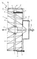
- the illustrated in the drawing Milling centrifuge comprises a frame 1, on which by means of two bearing elements 2 and 3 designed as bearing elements 4, a roller-shaped cutter body 5 is rotatably mounted about the axis 6.
- the cutter body 5 comprises two sections 7 and 8, between which a gear 9 is arranged.
- the gear 9 serves the drive shaft 10 with the cutter body shaft 11th
- a blast wheel 12 is rotatably connected, which is housed in a blast wheel housing 13, which in turn is connected to the frame 1 of the cutting spinner.
- the brush cutter comprises a plurality of blade-like free-cutting elements 16, which are connected via a carrier 17 with the hub 14 of the brush cutter 15.
- the front side is connected to the free cutting elements 16 a concentric with the axis 6 arranged ring 18.
- On the equipped with the brush cutter 15 side of the frame 1 extends up to about that ring 18 of the brush cutter.
- a - not shown - the cutter body 5 back covering snow guide can also extend behind the brush cutter 15 to (also) supply the loosened by the free cutting knives 16 snow the blast wheel 12.
Landscapes
- Engineering & Computer Science (AREA)
- Architecture (AREA)
- Civil Engineering (AREA)
- Structural Engineering (AREA)
- Harvester Elements (AREA)
- Road Repair (AREA)
- Earth Drilling (AREA)
- Shovels (AREA)
- Cleaning Of Streets, Tracks, Or Beaches (AREA)
Applications Claiming Priority (2)
| Application Number | Priority Date | Filing Date | Title |
|---|---|---|---|
| DE10013481A DE10013481C1 (de) | 2000-03-18 | 2000-03-18 | Schneefräse mit mindestens einem walzenförmigen Fräskörper |
| DE10013481 | 2000-03-18 |
Publications (3)
| Publication Number | Publication Date |
|---|---|
| EP1136626A2 EP1136626A2 (de) | 2001-09-26 |
| EP1136626A3 EP1136626A3 (de) | 2003-06-04 |
| EP1136626B1 true EP1136626B1 (de) | 2006-06-14 |
Family
ID=7635426
Family Applications (1)
| Application Number | Title | Priority Date | Filing Date |
|---|---|---|---|
| EP01105846A Expired - Lifetime EP1136626B1 (de) | 2000-03-18 | 2001-03-09 | Schneefräse mit mindestens einem walzenförmigen Fräskörper |
Country Status (4)
| Country | Link |
|---|---|
| EP (1) | EP1136626B1 (pl) |
| AT (1) | ATE330074T1 (pl) |
| DE (2) | DE10013481C1 (pl) |
| PL (1) | PL198800B1 (pl) |
Families Citing this family (1)
| Publication number | Priority date | Publication date | Assignee | Title |
|---|---|---|---|---|
| CN119609626B (zh) * | 2024-11-22 | 2025-11-11 | 天津电力机车有限公司 | 一种全悬挂机车驱动轴承压装装置 |
Family Cites Families (12)
| Publication number | Priority date | Publication date | Assignee | Title |
|---|---|---|---|---|
| DE818810C (de) * | 1950-05-22 | 1951-10-29 | Beilhack Maschf Martin | Schneeraeumgeraet |
| DE1018444B (de) * | 1954-05-20 | 1957-10-31 | Grossglockner Hochalpenstrasse | Schneeraeumgeraet mit waagerecht liegenden Raeumtrommeln |
| US3321851A (en) * | 1964-04-29 | 1967-05-30 | Earl H Fisher | Combination rotary broom and turbine |
| DE1918670A1 (de) * | 1968-07-11 | 1971-01-21 | Brenig Fa Karl & Josef | Tiefenlockerungsgeraet |
| CH542958A (de) * | 1970-08-19 | 1973-10-15 | Boschung Fa M | Schneefräse |
| FR2422771A1 (fr) | 1978-04-10 | 1979-11-09 | Tech Realisa Ingenieri Et | Dispositif de prelevement de neige |
| US4255879A (en) * | 1979-03-19 | 1981-03-17 | Amf Incorporated | Snow blower dead man control |
| DE2914229C2 (de) * | 1979-04-09 | 1983-12-22 | Ford-Werke AG, 5000 Köln | Längsverschiebbar gelagerter Kraftfahrzeugsitz |
| US4457086A (en) * | 1980-09-11 | 1984-07-03 | Gilson Brothers Company | Snowblower having improved auger and traction drive control |
| DE3304654A1 (de) * | 1983-02-10 | 1984-08-16 | Martin Beilhack Maschinenfabrik Und Hammerwerk Gmbh, 8200 Rosenheim | Schneeraeumeinrichtung |
| DE3720158A1 (de) * | 1986-06-18 | 1987-12-23 | Honda Motor Co Ltd | Schneeraeum-maschine mit eigenantrieb |
| JP3868586B2 (ja) * | 1997-08-08 | 2007-01-17 | 株式会社 神崎高級工機製作所 | 車軸駆動装置 |
-
2000
- 2000-03-18 DE DE10013481A patent/DE10013481C1/de not_active Expired - Fee Related
-
2001
- 2001-03-09 DE DE50110094T patent/DE50110094D1/de not_active Expired - Lifetime
- 2001-03-09 EP EP01105846A patent/EP1136626B1/de not_active Expired - Lifetime
- 2001-03-09 AT AT01105846T patent/ATE330074T1/de active
- 2001-03-14 PL PL346440A patent/PL198800B1/pl unknown
Also Published As
| Publication number | Publication date |
|---|---|
| PL198800B1 (pl) | 2008-07-31 |
| PL346440A1 (en) | 2001-09-24 |
| DE50110094D1 (de) | 2006-07-27 |
| EP1136626A3 (de) | 2003-06-04 |
| EP1136626A2 (de) | 2001-09-26 |
| ATE330074T1 (de) | 2006-07-15 |
| DE10013481C1 (de) | 2001-09-06 |
Similar Documents
| Publication | Publication Date | Title |
|---|---|---|
| DE3102598C2 (pl) | ||
| DE2908948C2 (pl) | ||
| BE1023926B1 (de) | Vorrichtung zur Erkennung der Schärfe von Schneidkanten von Häckselmessern einer Hächseltrommel eines Feldhäckslers | |
| EP0312827B1 (de) | Vorrichtung zum Reinigen eines Übertragungszylinders einer Rotationsdruckmaschine | |
| EP0442290A1 (de) | Stützwalze | |
| EP0795353B1 (de) | Schriftgutvernichter | |
| EP2319988B1 (de) | Heckanbaubaugerät für eine Pistenraupe | |
| DE2007716B2 (de) | Rotormähwerk | |
| DE2653463A1 (de) | Konditioniereinrichtung fuer landwirtschaftliches erntegut | |
| DE2131547C3 (de) | Vorrichtung zum Schneiden eines zylindrischen Stabes in eine vorgegebene Anzahl von Längenabschnitten | |
| DE2843782C2 (de) | Kreiselheuwerbungsmaschine zum Schwadenlegen oder Schwadenwenden oder zum Zetten/Wenden | |
| EP0320735B1 (de) | Handgeführte, fahrbare Reinigungsmaschine, insbesondere Schrubbmaschine | |
| DE2947340A1 (de) | Kreiselegge | |
| EP1000533B1 (de) | Pflückvorrichtung zum Ernten von Halmfrüchten | |
| DE10013481C1 (de) | Schneefräse mit mindestens einem walzenförmigen Fräskörper | |
| EP0188682B1 (de) | Kreiselmäher | |
| DE2721411B1 (de) | Schneeschleuder,insbesondere fuer den Anbau an Eisenbahnfahrzeuge | |
| DE4014752C2 (de) | Längsschneidarm für Vortriebs- und Abbauzwecke u. dgl. | |
| DE4124855A1 (de) | Stiftmuehle | |
| EP3251481B1 (de) | Einachsgeräteträger und anbaugerät für einen einachsgeräteträger | |
| DE69621191T2 (de) | Schleuderstrahlmaschine zum projektieren von schleifkörnern | |
| DE10325187B4 (de) | Spindelmäher | |
| DE3926976C2 (de) | Vorrichtung zum Einbringen eines im wesentlichen vertikalen Bodenschlitzes | |
| DE19751105B4 (de) | Schrotmühle | |
| EP0038320B1 (de) | Treibrollengerüst für Stranggiessanlagen |
Legal Events
| Date | Code | Title | Description |
|---|---|---|---|
| PUAI | Public reference made under article 153(3) epc to a published international application that has entered the european phase |
Free format text: ORIGINAL CODE: 0009012 |
|
| AK | Designated contracting states |
Kind code of ref document: A2 Designated state(s): AT BE CH CY DE DK ES FI FR GB GR IE IT LI LU MC NL PT SE TR |
|
| AX | Request for extension of the european patent |
Free format text: AL;LT;LV;MK;RO;SI |
|
| PUAL | Search report despatched |
Free format text: ORIGINAL CODE: 0009013 |
|
| AK | Designated contracting states |
Designated state(s): AT BE CH CY DE DK ES FI FR GB GR IE IT LI LU MC NL PT SE TR |
|
| AX | Request for extension of the european patent |
Extension state: AL LT LV MK RO SI |
|
| 17P | Request for examination filed |
Effective date: 20030712 |
|
| AKX | Designation fees paid |
Designated state(s): AT CH DE FR IT LI |
|
| 17Q | First examination report despatched |
Effective date: 20050504 |
|
| GRAP | Despatch of communication of intention to grant a patent |
Free format text: ORIGINAL CODE: EPIDOSNIGR1 |
|
| GRAS | Grant fee paid |
Free format text: ORIGINAL CODE: EPIDOSNIGR3 |
|
| GRAA | (expected) grant |
Free format text: ORIGINAL CODE: 0009210 |
|
| AK | Designated contracting states |
Kind code of ref document: B1 Designated state(s): AT CH DE FR IT LI |
|
| PG25 | Lapsed in a contracting state [announced via postgrant information from national office to epo] |
Ref country code: IT Free format text: LAPSE BECAUSE OF FAILURE TO SUBMIT A TRANSLATION OF THE DESCRIPTION OR TO PAY THE FEE WITHIN THE PRESCRIBED TIME-LIMIT;WARNING: LAPSES OF ITALIAN PATENTS WITH EFFECTIVE DATE BEFORE 2007 MAY HAVE OCCURRED AT ANY TIME BEFORE 2007. THE CORRECT EFFECTIVE DATE MAY BE DIFFERENT FROM THE ONE RECORDED. Effective date: 20060614 |
|
| REG | Reference to a national code |
Ref country code: CH Ref legal event code: EP |
|
| REG | Reference to a national code |
Ref country code: CH Ref legal event code: NV Representative=s name: ISLER & PEDRAZZINI AG |
|
| REF | Corresponds to: |
Ref document number: 50110094 Country of ref document: DE Date of ref document: 20060727 Kind code of ref document: P |
|
| ET | Fr: translation filed | ||
| PLBE | No opposition filed within time limit |
Free format text: ORIGINAL CODE: 0009261 |
|
| STAA | Information on the status of an ep patent application or granted ep patent |
Free format text: STATUS: NO OPPOSITION FILED WITHIN TIME LIMIT |
|
| 26N | No opposition filed |
Effective date: 20070315 |
|
| REG | Reference to a national code |
Ref country code: CH Ref legal event code: PCAR Free format text: ISLER & PEDRAZZINI AG;POSTFACH 1772;8027 ZUERICH (CH) |
|
| REG | Reference to a national code |
Ref country code: FR Ref legal event code: PLFP Year of fee payment: 15 |
|
| REG | Reference to a national code |
Ref country code: FR Ref legal event code: PLFP Year of fee payment: 16 |
|
| REG | Reference to a national code |
Ref country code: FR Ref legal event code: PLFP Year of fee payment: 17 |
|
| PGFP | Annual fee paid to national office [announced via postgrant information from national office to epo] |
Ref country code: FR Payment date: 20170323 Year of fee payment: 17 Ref country code: CH Payment date: 20170327 Year of fee payment: 17 |
|
| PGFP | Annual fee paid to national office [announced via postgrant information from national office to epo] |
Ref country code: AT Payment date: 20170322 Year of fee payment: 17 |
|
| PGFP | Annual fee paid to national office [announced via postgrant information from national office to epo] |
Ref country code: DE Payment date: 20170529 Year of fee payment: 17 |
|
| PGFP | Annual fee paid to national office [announced via postgrant information from national office to epo] |
Ref country code: IT Payment date: 20170323 Year of fee payment: 17 |
|
| REG | Reference to a national code |
Ref country code: DE Ref legal event code: R119 Ref document number: 50110094 Country of ref document: DE |
|
| REG | Reference to a national code |
Ref country code: CH Ref legal event code: PL |
|
| REG | Reference to a national code |
Ref country code: AT Ref legal event code: MM01 Ref document number: 330074 Country of ref document: AT Kind code of ref document: T Effective date: 20180309 |
|
| PG25 | Lapsed in a contracting state [announced via postgrant information from national office to epo] |
Ref country code: DE Free format text: LAPSE BECAUSE OF NON-PAYMENT OF DUE FEES Effective date: 20181002 Ref country code: AT Free format text: LAPSE BECAUSE OF NON-PAYMENT OF DUE FEES Effective date: 20180309 |
|
| PG25 | Lapsed in a contracting state [announced via postgrant information from national office to epo] |
Ref country code: IT Free format text: LAPSE BECAUSE OF NON-PAYMENT OF DUE FEES Effective date: 20180309 Ref country code: CH Free format text: LAPSE BECAUSE OF NON-PAYMENT OF DUE FEES Effective date: 20180331 Ref country code: LI Free format text: LAPSE BECAUSE OF NON-PAYMENT OF DUE FEES Effective date: 20180331 |
|
| PG25 | Lapsed in a contracting state [announced via postgrant information from national office to epo] |
Ref country code: FR Free format text: LAPSE BECAUSE OF NON-PAYMENT OF DUE FEES Effective date: 20180331 |