EP1133034B1 - Wavelength stabilized laser module - Google Patents
Wavelength stabilized laser module Download PDFInfo
- Publication number
- EP1133034B1 EP1133034B1 EP01250079A EP01250079A EP1133034B1 EP 1133034 B1 EP1133034 B1 EP 1133034B1 EP 01250079 A EP01250079 A EP 01250079A EP 01250079 A EP01250079 A EP 01250079A EP 1133034 B1 EP1133034 B1 EP 1133034B1
- Authority
- EP
- European Patent Office
- Prior art keywords
- wavelength
- filter
- semiconductor laser
- light
- laser module
- Prior art date
- Legal status (The legal status is an assumption and is not a legal conclusion. Google has not performed a legal analysis and makes no representation as to the accuracy of the status listed.)
- Expired - Lifetime
Links
Images


Classifications
-
- H—ELECTRICITY
- H01—ELECTRIC ELEMENTS
- H01S—DEVICES USING THE PROCESS OF LIGHT AMPLIFICATION BY STIMULATED EMISSION OF RADIATION [LASER] TO AMPLIFY OR GENERATE LIGHT; DEVICES USING STIMULATED EMISSION OF ELECTROMAGNETIC RADIATION IN WAVE RANGES OTHER THAN OPTICAL
- H01S5/00—Semiconductor lasers
- H01S5/02—Structural details or components not essential to laser action
- H01S5/022—Mountings; Housings
- H01S5/023—Mount members, e.g. sub-mount members
- H01S5/02325—Mechanically integrated components on mount members or optical micro-benches
-
- H—ELECTRICITY
- H01—ELECTRIC ELEMENTS
- H01S—DEVICES USING THE PROCESS OF LIGHT AMPLIFICATION BY STIMULATED EMISSION OF RADIATION [LASER] TO AMPLIFY OR GENERATE LIGHT; DEVICES USING STIMULATED EMISSION OF ELECTROMAGNETIC RADIATION IN WAVE RANGES OTHER THAN OPTICAL
- H01S5/00—Semiconductor lasers
- H01S5/06—Arrangements for controlling the laser output parameters, e.g. by operating on the active medium
- H01S5/068—Stabilisation of laser output parameters
- H01S5/0683—Stabilisation of laser output parameters by monitoring the optical output parameters
- H01S5/0687—Stabilising the frequency of the laser
Definitions
- the present invention relates to a wavelength stabilized laser module according to the preamble of claim 1, and more particularly to the wavelength stabilized laser module capable of emitting laser light whose wavelength is stabilized with high accuracy and of being so configured as to be simple in structure and being made smaller in size.
- a semiconductor laser device is used as an optical source for optical fiber communication.
- a single axial mode semiconductor laser such as a DFB (Distributed FeedBack) laser is employed, in particular, for optical fiber communication over distances of tens of kilometers or more in order to prevent an adverse effect on chromatic dispersion.
- the DFB laser oscillates at a single wavelength, its oscillation wavelength is changed depending on the temperature of the semiconductor laser device and/or an injected current.
- control is conventionally exercised so as to keep the temperature of the semiconductor laser device and the output strength of the semiconductor laser light source at the constant level.
- a DWDM (Dense Wavelength Division Multiplexing) method in which multiple pieces of light each having a different wavelength are multiplexed in one optical fiber becomes mainstream in the conventional optical fiber communication system and the interval among a plurality of the oscillation wavelengths used for the DWDM system becomes as narrow as 100 GHz or 50 GHz.
- the degree of wavelength stabilization required for the semiconductor laser device being used as the light source is, for example, ⁇ 50 pm, which means that conventional method in which temperatures of the semiconductor laser device and outputs of the semiconductor laser light are controlled so as to be kept at the constant level is not sufficient to obtain the required degree of wavelength stabilization.
- the temperature of the semiconductor laser itself can be successfully controlled sc as to remain constant, every time the ambient temperature around the semiconductor laser device changes, the oscillation wavelength is also changed slightly and cases are increasing in which such a slight change in the oscillation wavelength causes a problem in the recent conventional optical fiber communication system.
- a first example of the conventional wavelength stabilizing device (hereinafter being referred to as a first conventional example) is disclosed in, for example, Japanese Patent No. 2989775 (JP. Appln. Laid-open No. Hei 10-209546) in which, as shown in Fig. 19, a wavelength stabilizing device 128 is housed in a case mounted separately from a semiconductor laser module. A part of laser light is branched through a coupler 109 from an optical fiber transmission path 108 and introduced into the wavelength stabilizing device 128.
- a filter 103 serving as a band pass filter is embedded, and an optical detector 111 used to detect light transmitted through the filter 103 and an optical detector 110 used to detect light reflected off the filter 103 are placed opposite to each other.
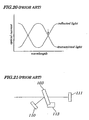
- Figure 20 is a diagram showing optical current spectra to explain operation of the wavelength stabilizing device 128. As shown in Fig. 20, the transmitted light detected by the optical detector 111 and the reflected light detected by the optical detector 110 are in opposite phase relative to the oscillation wavelength of the semiconductor laser light. By calibrating the filter 103 and the optical detectors 110 and 111 so that a point of intersection of the reflected light and transmitted light, which is indicated by an arrow in Fig.
- a slide adjusting unit 112 to set a reference wavelength to be used as a target for the stabilization is mounted on the filter 103.
- the conventional wavelength stabilizing device 128 presents problems since it is basically housed in the case mounted separately from the semiconductor laser module, additional space for its installation is required, thus causing an increase in costs. Moreover, since a part of the signal light is branched by the coupler 109, the branched light is attenuated.
- the targeted reference wavelength can be set only by adjusting the position of the filter 103 using the slide adjusting unit 112, a specially-fabricated expensive filter is required which is structured to change its transmission characteristics in a direction of its plane by gradually changing internal thickness of the filter. Furthermore, since transmission characteristics of a filter, in general, are changed depending on a temperature of the filter itself, a separate process of adjusting the temperature of the filter 103 or a special electric circuit that can compensate for changes in transmission characteristics caused by the temperature is required.
- a second example of the conventional wavelength stabilizing device adapted to prevent changes in oscillation wavelength of a semiconductor laser light and to stabilize its wavelength is disclosed in Japanese Patent No. 2914748 (JP. Appln. Laid-open No. Hei 4-157780) which is shown in Fig. 21.
- a basic principle of stabilizing the wavelength in this wavelength stabilizing device is the same as provided in the first conventional example; that is, a part of signal light is branched and incident on a filter 103, and reflected light and transmitted light from the filter 103 are detected by the optical detectors 110 and 111 respectively, which are then fed back to the temperature controlling unit (not shown) of the semiconductor laser.
- the second conventional example differs from the first conventional example in that a frequency setting section 113 is provided, which is used to adjust an angle of the filter 103.
- a third example of the conventional wavelength stabilizing device adapted to prevent changes in the oscillation wavelength of a semiconductor laser and to stabilize its wavelength is disclosed in Japanese Patent Application Laid-open No. Hei 9-219554, which is shown in Fig. 22.
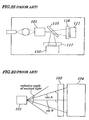
- This wavelength stabilizing device differs from the first and second conventional wavelength stabilizing devices in that light emitted from a semiconductor laser module 101 is branched by a beam splitter 115 having no dependence on a wavelength of light and each past of the branched light is received by optical detectors 110 and 111 respectively and that a filter 117 whose transmittance becomes low with decreasing wavelength of light is mounted in front of the optical detector 110 and a filter 116 whose transmittance becomes high with increasing wavelength of light is mounted in front of the optical detector 111.
- the wavelength of light emitted from the semiconductor laser module 101 can be stabilized.
- units adapted to adjust angles of the filters 116 and 117 for matching of the wavelength are required, since transmitted light is incident on both the filters 116 and 117, there is no need for adjusting positions of the optical detectors 110 and 111 when the angles of the filters 116 and 117 are adjusted.
- the semiconductor laser module 101 emits light at a relatively large radiation angle, as a distance between a surface from which the semiconductor laser is radiated and optical detectors 110 and 111 becomes far, strength of detection of the light rapidly decreases.
- a light receiving area of an optical detector 104 is made large in order to increase its detecting sensitivity, an area of the filter 103 on which light is incident also increases and a big difference in the angle of incidence on the filter 103 occurs due to reasons. That is the difference in the angle of incidence between rays A and B becomes large.
- the wavelength filter used in the example has a property in which its transmission characteristic depends greatly on the incident angle of light, regardless of whether the filter is of a multilayer type or of an etalon type, as is the case of the multilayer type shown in Fig. 24, there is a big difference in transmission characteristics between the rays A and B each having a big difference in the angle of incidence of light on the filter 103 and, as a result, in some cases, the dependence on wavelength in light receiving strength of the entire emitted laser becomes small or disappears. To avoid this problem, it is necessary to cause light emitted from the semiconductor laser module 101 to converge to be parallel luminous flux.
- a fourth example of the conventional wavelength stabilizing device adapted to prevent changes in the oscillation wavelength of a semiconductor laser and to stabilize its wavelength is disclosed in Japanese Patent Application Laid-open No. Hei 10-79723, which is shown in Fig. 25.
- the disclosed wavelength stabilizing device in order to obtain a signal whose transmittance becomes high with increasing wavelength and a signal whose transmittance becomes low with decreasing wavelength, light emitted from a semiconductor laser module 101 is adjusted by using a lens 102 so as to be emitted at a specified diffusion angle and the diffused light is then incident on a tilt filter 103a and the light transmitted through the tilt filter 103a is detected by an optical detector 104 having two light receiving planes 105 and 106. Since light to be incident on the light receiving planes 105 and light to be incident on the light receiving planes 106 differ from each other in incident angles on the tilt filter 103a, with only the one tilt filter 103a, plural different transmission characteristics can be provided.
- the fourth conventional example precise adjustment of optical systems employed in the wavelength stabilizing device is required and characteristics of light transmitted through the tilt filter 103a occurring when the light is incident on light receiving planes 105 and 106 are changed intricately due to changes in a diffusion angle of semiconductor laser light caused by an even slight change of the position of the lens 102, change in the angle of the tilt filter 103a, change in the position of the optical detector 104 or the like. That is, to independently control the tilt filter 103a transmitting characteristic affecting the incidence of the light on the light receiving planes 105 and 106 and to stabilize the wavelength so as to have a specified wavelength, highly accurate placement of each of parts making up the wavelength stabilizing device is required. For example, since it is impossible to stabilize the wavelength only by adjusting the angle of the tilt filter 103a, a problem occurs when the wavelength stabilizing device is actually fabricated.
- a fifth example of the conventional wavelength stabilizing device adapted tc prevent changes in the oscillation wavelength of a semiconductor laser and to stabilize its wavelength is disclosed in Japanese Patent Application Laid-open No. Hei 9-121070, which is shown in Fig. 26.
- backward emitted light from a semiconductor laser module 101 is branched by a beam splitter 115 and a branched light beam is incident directly on an optical detector 110 without being incident through a filter 103, which is used for detection of optical strength of the light, while another branched light beam is incident on an optical detector 111 through the filter 103, which is used for detectionof the wavelength of the light.
- an output from the semiconductor laser module 101 can be controlled so as to remain constant.
- the optical detector 110 used to detect light not passing through the filter 103 so that its optical current is made constant
- an output from the semiconductor laser module 101 can be controlled so as to remain constant.
- the light transmitted through the filter 103 as is understood from dependence of transmittance of the filter 103 on wavelengths, that is, dependence of an optical current "I" of the optical detector 111 on the wavelength as shown in Fig. 5
- the output of the light and its oscillation wavelength can be simultaneously controlled.
- EP 0818 857 A 1 and US 4 821 273 disclose a wavelength stabilized laser module according to the preamble of claim 1.
- WO 99 27664 A1 discloses a wavelength stabilized laser module where a single filter with spatially varying transmission/reflection characteristics is used for both parts of the luminous flux.
- JP 58 056539 A discloses a laser module without temperature adjusting unit and with two additional lenses for focussing the light of the two light paths on the corresponding photodetectors.
- the first photoelectric converting unit can take out optical currents that change depending on an optical output from the semiconductor laser and the second converting unit can take out optical currents that change depending on an optical output fed from the semiconductor laser and depending on wavelengths. Therefore, by performing computations of the two optical currents taken from the wavelength stabilized laser module, each of a current value that changes depending on the optical output and a current value that changes depending on wavelengths can be independently obtained.
- Variations in optical outputs from the semiconductor laser have been detected by the first photoelectric converting unit, by feeding back the output shifted signal to the semiconductor laser, optical outputs from the semiconductor laser are stabilized with high accuracy. Furthermore, since parts such the beam splitter as has been used conventionally are not employed to obtain a signal that changes depending on the wavelength and a signal that does not change depending on wavelength, the amount of component can be reduced and the space usage efficiency made higher, thus enabling configuration of the wavelength stabilized laser module to be compact enough to be housed in such the tightly-spaced case as has been used for the conventional semiconductor laser module and, since the adjustment and assembly at the time of manufacturing of the module are made simpler due to reduced component counts, manufacturing costs are greatly reduced.
- the second photoelectric converting unit can immediately detect the wavelength of the laser light that changes on a long wavelength side or a short wavelength side relative to the reference wavelength, as a change on a bright side or a dark side of the light transmitted through the filter.
- the gradient in changes in transmittance that changes depending on the wavelength can be varied by adjusting the angle of incidence, by making the gradient sharp, detecting sensitivity to changes in wavelengths can be improved and the stabilization of wavelengths with high accuracy is made possible, while, by making the gradient gentle, a band width of wavelength in which changes are detected can be expanded.
- the reference wavelength is in a maximum transmission band or in a minimum transmission band of the transmission characteristic, the sensitivity to changes in the wavelengths is greatly lowered.
- the transmission characteristic is unimodal, in a wide band of wavelengths except the maximum transmission band or the minimum transmission band being limited bands, detection of wavelengths with high sensitivity is made possible.
- thickness of a glass substrate can be set arbitrarily, thus enabling the substrate to be thin and achieving the compact wavelength stabilized laser module.
- each of the reference wavelengths can be set to be placed on the gradient of the spectrum between each of the maximum points and each of the minimum points and stabilization of the plurality of the reference wavelengths can be achieved in the multiple optical system using, as the light source, the wavelength tunable semiconductor laser in the single wavelength stabilized laser module.
- the transparent base material having high reflectivity as the material for the etalon-type filter or multilayer filter rather than silica glass that has been conventionally used, thickness of the filter can be made thin and the space required for mounting the wavelength stabilized laser module can be further reduced.
- the Si-based material is transparent and has reflectivity being higher than that of silica glass and is a relatively low-cost material widely used in the semiconductor fields and therefore it is best suitable as material for the filter of the present invention.
- the component number of the wavelength stabilizing device is small and adjustment is made easy, it can be housed in such a small-sized case as has been conventionally used for housing the semiconductor laser module with no wavelength stabilizing device.
- the wavelength stabilized laser module of Fig. 1 includes a case 9, a semiconductor laser 1, a lens 2 used to convert backward emitted light radiated from the semiconductor laser 1 in a diffused manner to parallel luminous flux, a first photoelectric converter 5 used to directly receive a part of the parallel luminous flux transmitted through the lens 2 and to convert it to an electric signal, an etalon-type filter 31 to receive a part of the parallel luminous flux transmitted through the lens 2 and a second photoelectric converter 6 to receive light transmitted through the etalon-type filter 31 and to convert it to an electric signal.
- the semiconductor laser 1 is mounted on a substrate 7 having a Peltier device (not shown) and the substrate 7 is so constructed that the temperature of the semiconductor laser is adjustable by the Peltier device while the semiconductor laser 1 is being operated.
- the etalon-type filter 31 is so configured that an angle of incidence of light can be calibrated by an angle calibrating mechanism (not shown).
- the first photoelectric converter 5 and the second photoelectric converter 6 are mounted in parallel on a holding substrate 49, making up an array-shaped optical detector 4.
- the array-shaped optical detector 4 is placed in tilted manner relative to an optical axis of incident light to prevent feedback light reflected toward the semiconductor laser 1.
- the wavelength stabilized laser module of the embodiment when laser light is emitted from the semiconductor laser 1, its backward emitted light is incident on the lens 2 and is converted to parallel luminous flux and a part of the parallel luminous flux is directly incident on the first photoelectric converter 5 to be converted to a corresponding electric signal "A". Another part of the parallel luminous flux is incident on the etalon-type filter 31.
- the etalon-type filter 31 transmits light whose transmittance has changed depending on the wavelength of the incident light and the transmitted light is incident on the second photoelectric converter 6 to be converted to a corresponding electric signal "B".
- the electric signal "A" has information about the optical output from the semiconductor laser 1 at the time and the electric signal B has information containing both information about the optical output from the semiconductor laser 1 at the time and about the wavelength of light being emitted by the semiconductor laser 1 at the time.
- the electric signal B transmits information about a reference wavelength to be used as a target for stabilization of wavelengths and about changes in the wavelengths straddling the reference wavelength to an operation circuit 8 at a desired sensitivity.
- the electric signals A and B are taken from the wavelength stabilized laser module of the first embodiment and are transmitted to the operation circuit 8.
- the operation circuit 8 detects change in the light output of the semiconductor laser 1 from the change in the electric signal A and feeds back the difference between a present output and a reference output as an output shifting signal continuously to an injected current adjusting device (not shown) to stabilize its wavelength of the semiconductor laser light.
- the operation circuit 8 takes a signal component that changes depending on a wavelength from electric signals A and B and, by referring to spectrum data of transmittance for a wavelength stored in advance in the operation circuit 8, calculates a wavelength of light being presently emitted from the semiconductor laser 1 and produces a wavelength shifting signal showing the difference between the wavelength of the light being presently emitted and a reference wavelength to be used as a target for stabilization of wavelengths.
- the wavelength shifting signal is fed back to either of or both of the injected current adjusting device (not shown) or the peltier device (not shown) mounted on the substrate 7, thereby stabilizing wavelengths of an output from the semiconductor laser 1.
- the wavelength stabilized laser module of the first embodiment has advantages in that, since parts such as a beam splitter used to obtain a signal that changes depending on the wavelength and a signal that does not change depending on the wavelength is not mounted and one single lens 2 is used, the number of components is reduced and efficiency of using space is excellent and, since the wavelength stabilized laser module constructed sufficiently compact to be housed in a tightly-spaced case that has housed the conventional semiconductor laser module, assembling and adjusting processes at the time of manufacturing are made simple and manufacturing costs are greatly reduced.
- the etalon-type filter 31 is also called a Fabry-Perot interferometer, which has a characteristic to permit light with a very narrow band width of wavelengths only to pass by interference of light.
- the etalon-type filter 31 is basically an optical glass of parallel shape with a thickness of "d", whose plane of incidence and emission is polished with high accuracy (about 1/100 of a wavelength). Within the optical glass having an index of refraction "n" occurs a multiple reflection of light.
- the etalon-type filter 31 exhibits a characteristic in which transmittance of the light changes repeatedly due to interference between reflected light and transmitted light, as shown in Fig. 4.
- the interval between peaks of the transmittance, as shown in Fig. 4, is called an FSR (Free Spectral Range).
- a reference wavelength ⁇ 0 to be used as the target for the stabilization of the wavelength ⁇ is set within a band of wavelengths where the transmittance of the etalon-type filter 31 becomes high or low monotonically, as shown in Fig. 5.
- the point at which the reference wavelength ⁇ 0 is set in the transmittance spectrum is referred to as a wavelength stabilized point "S".
- the wavelength stabilized point "S" is set at midpoint of a band width in which the transmittance becomes low monotonically at a right shoulder of its plotted declined line.
- the transmittance (that is, a value converted to an optical current) of the etalon-type filter 31 at point "S" being a reference wavelength ⁇ 0 is I0
- the transmittance becomes lower than the transmittance I0
- the transmittance becomes higher than the transmittance I0.
- a reference value of an optical current detected by the first photoelectric converter 5 is set so that a forward optical output from the semiconductor laser 1 becomes, for example, 20 mW and the injected current to the semiconductor laser 1 is controlled so that this reference value is maintained all the time. In this state, the optical output remains constant. Moreover, by temperature control of the semiconductor laser 1 so that the optical current from the second photoelectric converter 6 remains the reference current value (that is, reference transmittance) "I0" relative to the wavelength stabilized point "S" indicated by the arrow in FIG. 5, the wavelength ⁇ of the semiconductor laser can be stabilized.
- a method for forming a feedback loop by using an analog electronic circuit or a software feedback method to convert the temperature to digital data using an A/D converter and to construct a control circuit on a computer may be used.
- oscillation wavelength of the semiconductor laser 1 is changed not only by the temperature of the semiconductor laser 1 but also by the injected current, while the optical output is changed not only by the injected current but also by the temperature of the semiconductor laser 1. Therefore, to keep the optical output at a constant level by controlling the optical current of the first photoelectric converter 5 shown in Fig. 1, a feedback loop adapted to simultaneously control the injected current and the temperature of the semiconductor laser 1 may be used. Similarly, to keep the oscillation wavelength constant by controlling the optical current of the second photoelectric converter 6, a feedback loop adapted to simultaneously control the injected current and the temperature of the semiconductor laser 1 may be employed.
- controllability of wavelength ⁇ of the wavelength stabilized laser module depends greatly on the transmission characteristic of the etalon-type filter 31.
- the gradient at the shoulder portion in a transmittance period including the wavelength stabilized point "S", i. e. the value of dI/d ⁇ is very important because it has great influence on the gain of the feedback loop.
- the transmission characteristic of the etalon-type filter changes depending greatly on reflectivity of the plane of incidence and emission, as shown in Fig. 7.
- the transmission characteristic is featured by such a sharply declined line of transmittance as were to be approximated by a delta function and the gradient dI/d ⁇ at a wavelength stabilized point S1 becomes large.
- the band width of wavelengths that can provide stabilization of wavelengths is made smaller.
- the transmission characteristic is featured by a sine-curve-like line showing the transmittance, the band width of the wavelengths that can provide stabilization of wavelengths is made larger.
- the gradient dI/d ⁇ at a wavelength stabilized point S2 becomes smaller.
- stability of the wavelength with high accuracy it is preferable to increase the reflectivity of the plane of incidence and emission of the etalon-type filter 31.
- a wide band of wavelengths rather than the stability of the wavelength is required, it is preferable to decrease the reflectivity of the plane of incidence and emission of the etalon-type filter 31.
- the FSR of the etalon-type filter 31 is effective.
- the FSR has to be made larger and the reflectivity of the plane of incidence of the etalon-type filter 31 has to be made smaller. If the gradient dI/d ⁇ is large enough to stabilize the wavelength, the etalon-type filter 31 having an arbitrary FSR can be used for the wavelength stabilized laser module of the present invention.
- transmission characteristics of the etalon-type filter 31 can be freely changed only by the calibration of the angle of incidence of the etalon-type filter 31.
- the FSR of the etalon-type filter is pre-set to a very narrow value of 100 GHz (0.8 nm)
- reflectivity of the plane of incidence is pre-set to a relatively high level of about 60%
- the incident angle of parallel luminous flux into a light receiving surface of the etalon-type filter 31 is set to be 0°
- the gradient at a wavelength stabilized point Sa is very large.
- the transmission spectrum in other words the peak wavelength is shifted as shown in Fig. 8(b) and 8(c)
- the transmission spectrum in other words the peak wavelength is shifted by its width, that is, by one period.
- the wavelength stabilized laser module of the present invention only by adjusting the angle of the etalon-type filter 31, it is made possible to set the reference wavelength ⁇ 0 for the stabilization of the wavelength ⁇ of the laser light and to calibrate the gradient at the wavelength stabilized point S, which is an important parameter in the feedback loop for the stabilization of wavelengths.
- the wavelength stabilized laser module When the wavelength stabilized laser module is applied to the DWDM method in the optical communication systems, a very high wavelength accuracy has to be ensured.
- the increased gradient at the wavelength stabilized point S is effective. That is, it is necessary to increase the amplitude (ON/OFF ratio) of the wave showing the transmittance of the etalon-type filter 31. If e. g. and as shown in Fig.
- the degree of parallelization of parallel luminous flux which has been converged by the lens 2 is low, that is, if a beam angle shifted from parallel position is large and if the beam is spread or narrowed, light incident on the etalon-type filter 31 at a different angle is included in light received by the second photoelectric converter 6 (the beam angle shifted from a parallel position being referred to as a "beam shifted angle").
- the transmission characteristic of the etalon-type filter 31 is dependent on the incident degree, if there is a variable range of the degree of incidence of light, a band width occurs in the wavelength of the light transmitted through the etalon-type filter 31.
- this band width of wavelengths is hereinafter called a "light receiving wavelength width".
- this light receiving wavelength width must be narrower.
- the degree of parallelization of light that can cause the light receiving wavelength to be, for example, not more than 100 pm.
- Figure 18 is a graph showing an example of relationship between the light receiving wavelength width and a beam shifted angle.
- a diameter of light received by the second photoelectric converter 6 is 0.05 mm the position of a light receiving plane of the lens 2 deviates by 0.2 mm from a center,the distance between a position of a main surface of the lens to a position of its light receiving plane and the etalon-type filter 31 is displaced vertically to optical axis X.
- the degree (that is, the beam shifted angle) of parallelization of the parallel luminous flux which has converged by the lens 2 is preferably within ⁇ 2°.
- a method of causing the degree of parallelization to be within ⁇ 2° is simpler when compared with a method in which, for example, a lens used to gather light in optical fibers is mounted with high accuracy.
- the method of causing the degree of parallelization to be within ⁇ 2° does not require expensive optical devices such as an aspherical lens or a like.
- the wavelength stabilized laser module of the first embodiment is such that a lens 18 used to connect optical an optical isolator 21, a thermistor 29 used to detect temperatures or the Like are mounted on the substrate 7 and embedded, together with the semiconductor laser 1, lens 2, etalon-type filter 31, array-shaped optical detector 4 having first photoelectric converter 5 and second photoelectric converter 6, in such case 9 as has been used for housing the conventional semiconductor laser module.
- An optical fiber 14 is connected to the case 9 to emit light for optical communication.
- the temperature of the substrate 7 is controllable by using the Peltier device attached to the substrate 7 which controls the temperature of the semiconductor laser device 1, thus stabilizing oscillation wavelengths of the laser light.
- the semiconductor laser module of the embodiment of the present invention are so compact that it can be housed in such case 9 as has been used for housing the conventional semiconductor laser module.
- the semiconductor laser module whose wavelength is stabilized with high accuracy can be implemented.
- the wavelength stabilizing device represents an assembly including, at least, the semiconductor laser, lens, filter, first and second photoelectric converters which are embedded in the wavelength stabilized laser module.
- Configuration of the wavelength stabilizing device of the second embodiment is substantially the same as of the first embodiment.
- a multilayer filter 32 made of dielectric multilayers formed on a glass substrate is used.
- the multilayer filter 32 is advantageous because the thickness of a glass substrate can be arbitrarily set and the substrate made thinner and compact. Effects or usage methods of the wavelength stabilizing device of the second embodiment are substantially the same as those of the first embodiment.
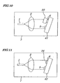
- Figure 10 shows configurations of the wavelength stabilizing device of the third embodiment differing from the first embodiment in that a filter 33 used to obtain a signal being dependent on wavelength is affixed to one of two photoelectric converters 5 and 6 (in this case, to the photoelectric converter 6) in a fixed manner.
- a filter 33 used to obtain a signal being dependent on wavelength is affixed to one of two photoelectric converters 5 and 6 (in this case, to the photoelectric converter 6) in a fixed manner.
- any one of filters including an etalon-type filter used in the first embodiment, a multilayer filter used in the second embodiment and other filters having same functions may be employed.
- adjustment of the wavelength in a transmission period and of a gradient of transmittance being dependent on wavelength, and optimization of optical detection strength can be implemented easily by optimizing angle or position relative to an optical axis of a filter-integrated optical detector 41.
- the wavelength stabilized laser module has a merit in that the wavelength stabilizing device which has become more compact is embedded.
- Figure 11 shows configurations of a wavelength stabilizing device according to a fourth embodiment differing from those of the first embodiment in that a filter 34 used to obtain a signal being dependent on wavelength is formed by a coating process to one of a first photoelectric converter 5 and second photoelectric converter 6 (in this case, to the second photoelectric converter 6) . That is, the filter 34 is formed in a manner that a light receiving plane of the second photoelectric converter 6 is directly coated with dielectric multilayer films.
- the second photoelectric converter 6 also serves as a substrate of a dielectric multilayer, it is possible to reduce the number of parts further and to decrease thickness of an optical detector 42 when compared with the third embodiment, thus enabling to provide a more compact wavelength stabilized laser module.
- Figure 12 shows configurations of a wavelength stabilized laser module according to a fifth embodiment which configurations are substantially the same as those of the first embodiment, however, differ from those in that a semiconductor laser 11 having a configuration of a device integrated with an electro-absorption-type semiconductor optical modulator is used.
- This semiconductor laser 11 is so configured as to be integral with the electro-absorption-type optical modulator, unlike a case where a widely-used DFB laser and an outside optical modulator are separately constructed as an independent module; this is particularly beneficial because the optical transmission system can be made more compact as a whole.
- Figure 13 shows configurations of a wavelength stabilizing device employed in a wavelength stabilized laser module according to a sixth embodiment which are substantially the same as in the first embodiment, however, differ from those in that a wavelength tunable semiconductor laser 12 and an etalon-type filter 35 having an FSR being 90 GHz are used.
- the wavelength tunable semiconductor laser 12 will be described.
- the wavelength tunable semiconductor laser 12 even in the case of a semiconductor laser device, can change its oscillation wavelength.
- a light source unit including a different semiconductor laser that can be used for each of channels each having a different wavelength is required.
- Backup light units in a same number of the light source units are also necessary and, therefore, as the number of channels in the DWDM communication system increases, costs for the backup light units tend to increase. If a wavelength tunable semiconductor laser can serve as back-up for a plurality of channels, costs may be reduced.
- the wavelength tunable semiconductor laser 12 having a most general configuration and is becoming commercially practical is a type of laser that can change oscillation wavelength by controlling the temperature of a conventional DFB semiconductor laser.
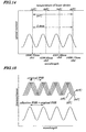
- the DFB semiconductor laser device emitting laser light in a band of wavelength being 1.55 nm
- its oscillation wavelength changes by about 1 nm. That is, as shown in Fig. 14, a wavelength of 2.4 nm being equivalent to 4 channels can be covered by changing the temperature of the DFB semiconductor laser device by ⁇ 12° at an interval of 100 GHz (0.8 nm)
- the wavelength tunable semiconductor laser 12 that can cover the above four channels is embedded in the wavelength stabilized laser module of the sixth embodiment.
- control on stabilization of wavelengths at a plurality of wavelengths at the same interval can be implemented by configuring the wavelength stabilizing device using an etalon-type filter 35 having the same FSR as the wavelength interval so that a transmittance period being different for every reference wavelength for stabilization is detected.
- a widely-used silica-based glass generally used as a material for the etalon-type filter 35 is dependent on temperatures of the semiconductor laser device. For example, as in the case of the first embodiment, to stabilize one reference wavelength, a range of temperatures to be controlled can be within ⁇ 1°C.
- the influence by temperature characteristics of the etalon-type filter 35 is not negligible.
- the position of a central wavelength is shifted by 0.1 nm.
- the etalon-type filter 35 and the wavelength tunable semiconductor laser 12 are mounted on the substrate 7 providing the same calibrated temperature to both of them so that the temperature of the etalon-type filter 35 and the wavelength tunable laser 12 can be controlled to be kept at the same level
- transmittance of the etalon-type filter 35 exhibits dependence on the wavelength with changing temperatures of the substrate 7, as shown in a lower part of Fig. 15. That is, the FSR of the etalon-type filter 35 is made wider than its original FSR at a time of actual operation .
- the FSR to be used in actual operation is called an "effective FSR". Therefore, by setting the effective FSR to 100 GHz (0.8 nm) being used for a wavelength interval in the DWDM system, the stabilization of the wavelength for each channel is made possible.
- the central wavelength represents a wavelength at which the transmittance becomes maximum.
- a method for stabilizing a plurality of reference wavelengths in the wavelength tunable semiconductor laser 12 will be described.
- the wavelength tunable semiconductor laser 12 which operates at wavelengths covering ch 1 (channel 1) to ch 4 (channel 4) (1555.75 nm to 1558.17 nm) is used.
- Operating temperatures of the semiconductor laser device during ch 1 to ch 4 are (see Fig. 14) 18°C, 26°C, 34°C and 42°C, respectively.
- the original FSR of the etalon-type filter 35 has to be 90 GHz. Then, by adjusting the angle of the etalon-type filter 35, the dependence of the transmittance on the wavelength at each of the temperatures is as shown in the upper part of Fig. 15 and the effective FSR can be almost 100 GHz as shown in the lower part of Fig. 15.
- the etalon-type filter 35 having the above setting in front of a second photoelectric converter 6 for monitoring the wavelength, the stabilization of the wavelength for each channel can be made possible, as in the case of the first embodiment.
- the stabilization of the wavelength is performed by using the gradient at the right shoulder of the transmittance period of the etalon-type filter 35, it is needless to say that the same effect can be achieved by using the gradient at the left shoulder of the transmittance period. Moreover, it is possible to perform the stabilization of the wavelength at an interval of half of the FSR, that is, at an interval of 50 GHz, by using the gradients at the right and left shoulders of the transmittance period. However, in this case, since the control direction for each channel in a feedback loop is reversed, correction in the wavelength stabilized laser module is required.
- the original FSR of the etalon-type filter 35 is set at 90 GHz, however, since an optimum value of the original FSR varies depending on temperature characteristics of the etalon-type filter 35, the FSR has to be set after the temperature characteristics of the etalon-type filter 35 have been obtained.
- the accuracy required when the effective FSR is matched with the intervals of the plurality of reference wavelengths is about ⁇ 3%. However, the required accuracy varies depending on a band of the wavelength that can be stabilized and on the number of wavelength channels to be stabilized and, therefore, when the band of the wavelength that can be stabilized is narrow or when the number of wavelength channels to be stabilized is large, increased accuracy is required accordingly.
- Figure 16 shows configurations of a wavelength stabilizing device according to a seventh embodiment which are substantially the same as those of the first embodiment, however, differ in that an etalon-type filter 36 using Si (silicon) material is used as a filter to obtain a signal depending on wavelength.
- Si silicon
- the etalon-type filter made of silica-based material is used, such material is expensive.
- Si-based material costs for manufacturing and working can be reduced.
- the Si-based etalon-type filter used for transmitting light having wavelengths of 1.3 nm to 1.6 nm in optical communication is almost transparent and can be used as a filter having a low-loss characteristic.
- micro-machining technology having approached maturity in recent years can be applied to the Si-based filter and that, by using such micro-machining technology, very highly accurate adjustment of angles or position of the Si-based substrate etalon-type filter can be implemented.
- thickness of the etalon-type filter can be reduced when an FSR is set to a small value being not more than 50 GHz in particular, if silica-based material is used, thickness of the etalon-type filter becomes not less than 2 mm, thus causing diffraction light at an edge of the etalon-type filter to be incident on a first photoelectric converter 5 and malfunctions to occur. If Si-based material is used for the etalon-type filter substrate, even if the FSR is as small as 50 GHz, thickness of the etalon-type filter becomes about 1 mm, which solves the above problem.
- the embodiments of the present invention by having a device used to convert emitted semiconductor laser light to parallel luminous flux, a first photoelectric converting device used to receive a part of the parallel luminous flux and to convert it to an electric signal, a filter used to receive a part of the parallel luminous flux and to continuously change its transmittance depending on a wavelength of the parallel luminous flux and a second photoelectric converting device used to receive light transmitted through the filter and to convert it to an electric signal, component counts are reduced and a space to house related parts is efficiently used, thus enabling configurations of the wavelength stabilizing device to be compact enough to be housed in a case as has been used for housing the conventional semiconductor laser module and, since adjustment and assembly at the time of manufacturing are simpler due to reduced number of components, production costs can be greatly reduced.
- a first photoelectric converter and second photoelectric converter are configured to be integral with an optical detector in a manner that these two converters make up an optical detector having two array-shaped light receiving planes, however, each of these first and second photoelectric converters may be arranged in parallel separately as a single unit.
- characteristics and/or light receiving surface areas of each of the converters may be the same or different.
Landscapes
- Physics & Mathematics (AREA)
- Condensed Matter Physics & Semiconductors (AREA)
- General Physics & Mathematics (AREA)
- Electromagnetism (AREA)
- Optics & Photonics (AREA)
- Semiconductor Lasers (AREA)
- Optical Couplings Of Light Guides (AREA)
Applications Claiming Priority (2)
| Application Number | Priority Date | Filing Date | Title |
|---|---|---|---|
| JP2000067606A JP2001257419A (ja) | 2000-03-10 | 2000-03-10 | 波長安定化レーザモジュール |
| JP2000067606 | 2000-03-10 |
Publications (3)
| Publication Number | Publication Date |
|---|---|
| EP1133034A2 EP1133034A2 (en) | 2001-09-12 |
| EP1133034A3 EP1133034A3 (en) | 2003-11-12 |
| EP1133034B1 true EP1133034B1 (en) | 2005-05-18 |
Family
ID=18586771
Family Applications (1)
| Application Number | Title | Priority Date | Filing Date |
|---|---|---|---|
| EP01250079A Expired - Lifetime EP1133034B1 (en) | 2000-03-10 | 2001-03-10 | Wavelength stabilized laser module |
Country Status (5)
| Country | Link |
|---|---|
| US (1) | US6788717B2 (ja) |
| EP (1) | EP1133034B1 (ja) |
| JP (1) | JP2001257419A (ja) |
| CA (1) | CA2340315A1 (ja) |
| DE (1) | DE60110855D1 (ja) |
Families Citing this family (41)
| Publication number | Priority date | Publication date | Assignee | Title |
|---|---|---|---|---|
| JP2001284711A (ja) * | 2000-03-31 | 2001-10-12 | Hitachi Ltd | 光伝送装置及びこれを用いた光システム |
| US6671296B2 (en) * | 2000-10-10 | 2003-12-30 | Spectrasensors, Inc. | Wavelength locker on optical bench and method of manufacture |
| JP4084006B2 (ja) * | 2001-06-27 | 2008-04-30 | 株式会社日立製作所 | 半導体レーザ制御モジュールとその応用装置 |
| JP2003101133A (ja) | 2001-09-20 | 2003-04-04 | Sumitomo Electric Ind Ltd | 発光モジュール |
| US7289544B2 (en) | 2001-09-20 | 2007-10-30 | Sumitomo Electric Industries, Ltd. | Optical module |
| JP4190749B2 (ja) * | 2001-09-28 | 2008-12-03 | 古河電気工業株式会社 | レーザモジュール |
| US7680364B2 (en) | 2001-10-09 | 2010-03-16 | Infinera Corporation | Wavelength locking and power control systems for multi-channel photonic integrated circuits (PICS) |
| JP3993409B2 (ja) * | 2001-10-17 | 2007-10-17 | 日本オプネクスト株式会社 | 光モジュール及びその製造方法 |
| US7061947B2 (en) * | 2001-11-01 | 2006-06-13 | Agility Communications, Inc. | Partially mirrored beam tap for wavelength lockers |
| JP4284974B2 (ja) * | 2001-11-15 | 2009-06-24 | 住友電気工業株式会社 | 光モジュール |
| WO2003056669A1 (fr) * | 2001-12-26 | 2003-07-10 | Mitsubishi Denki Kabushiki Kaisha | Appareil controleur de longueur d'onde, module optique, et procede d'assemblage du module optique |
| JP3895608B2 (ja) * | 2002-01-30 | 2007-03-22 | 古河電気工業株式会社 | 光モジュール、光送信器及びwdm光送信装置 |
| JP4190775B2 (ja) | 2002-03-05 | 2008-12-03 | Necエレクトロニクス株式会社 | 波長安定化半導体レーザモジュール |
| WO2003088436A1 (fr) * | 2002-04-15 | 2003-10-23 | Mitsubishi Denki Kabushiki Kaisha | Appareil de controle de longueur d'onde |
| US20030222209A1 (en) * | 2002-06-04 | 2003-12-04 | Mitchell Phillip V. | Compact, large angle beam stabilization module |
| WO2004010551A1 (ja) * | 2002-07-24 | 2004-01-29 | Ntt Electronics Corporation | レーザモジュール及びレーザモジュールの製造方法 |
| JP2004179427A (ja) * | 2002-11-27 | 2004-06-24 | Jfe Steel Kk | 半導体レーザのレ−ザ光出力波長制御方法及び半導体レーザ発振装置 |
| JP2004247585A (ja) * | 2003-02-14 | 2004-09-02 | Nec Compound Semiconductor Devices Ltd | 波長安定化ユニット及び波長安定化光送信モジュール |
| JP4322812B2 (ja) * | 2003-03-19 | 2009-09-02 | 三菱電機株式会社 | 波長フィルタおよび波長モニタ装置 |
| JP4713073B2 (ja) * | 2003-10-30 | 2011-06-29 | 富士通株式会社 | 波長可変レーザ及びその制御方法 |
| US8231098B2 (en) | 2004-12-07 | 2012-07-31 | Newport Corporation | Methods and devices for active vibration damping of an optical structure |
| KR100701121B1 (ko) * | 2004-12-08 | 2007-03-28 | 한국전자통신연구원 | 파장 가변 레이저 다이오드의 측정 시스템 및 방법 |
| JP4774761B2 (ja) * | 2005-03-03 | 2011-09-14 | 日本電気株式会社 | 波長可変共振器、波長可変レーザ、光モジュール及びそれらの制御方法 |
| EP1899754B1 (en) * | 2005-06-30 | 2020-04-08 | Infinera Corporation | Feedback system for a monolithic photonic integrated circuit |
| US20070003285A1 (en) * | 2005-06-30 | 2007-01-04 | Meyer A D | Optical signal source wavelength stabilization system and method |
| WO2007004509A1 (ja) | 2005-07-01 | 2007-01-11 | Nec Corporation | 外部共振器型波長可変レーザ装置および光出力モジュール |
| JP2007058902A (ja) * | 2005-08-22 | 2007-03-08 | Funai Electric Co Ltd | 光ピックアップ |
| TW200722805A (en) * | 2005-12-09 | 2007-06-16 | Ind Tech Res Inst | Canted-fiber base duplex optical subassembly |
| JP2006324636A (ja) * | 2006-03-03 | 2006-11-30 | Yamatake Corp | レーザ発振波長検出方法、制御方法および装置 |
| JP2008053466A (ja) * | 2006-08-24 | 2008-03-06 | Nec Electronics Corp | 光送信モジュール |
| CN102066907B (zh) * | 2008-03-28 | 2014-06-25 | 株式会社堀场制作所 | 光分析计和分析计用波长稳定化激光装置 |
| JP2011077069A (ja) * | 2009-09-29 | 2011-04-14 | Nippon Telegr & Teleph Corp <Ntt> | 波長可変光源モジュール及び波長可変光送信器 |
| KR101342097B1 (ko) * | 2011-10-26 | 2013-12-18 | 한국전자통신연구원 | 다채널 광모듈 |
| JP6165074B2 (ja) * | 2013-03-25 | 2017-07-19 | 三菱電機株式会社 | 波長モニタ及び波長モニタリング方法 |
| TWI453370B (zh) * | 2013-08-09 | 2014-09-21 | 3Dfamily Technology Co Ltd | 可見光之即時波長修正系統 |
| CN104949614A (zh) * | 2014-06-24 | 2015-09-30 | 常州和悦光电科技有限公司 | 一种对激光位移干涉仪提供实时波长修正之系统与装置 |
| JP6427443B2 (ja) * | 2015-03-12 | 2018-11-21 | 日立オートモティブシステムズ株式会社 | モータの駆動制御ユニット |
| JP6811835B2 (ja) | 2017-02-17 | 2021-01-13 | ギガフォトン株式会社 | レーザ装置 |
| CA3061993A1 (en) | 2017-05-22 | 2018-11-29 | Brolis Sensor Technology, Uab | Tunable hybrid iii-v/ iv laser sensor system-on-a-chip for real-time monitoring of a blood constituent concentration level |
| WO2019149815A1 (en) * | 2018-02-02 | 2019-08-08 | Uab Brolis Semiconductors | Wavelength determination for widely tunable lasers and laser systems thereof |
| CN112397995B (zh) * | 2019-08-02 | 2022-02-15 | 苏州旭创科技有限公司 | 一种窄线宽固定波长激光器及光模块 |
Family Cites Families (29)
| Publication number | Priority date | Publication date | Assignee | Title |
|---|---|---|---|---|
| JPS5655087A (en) | 1979-10-12 | 1981-05-15 | Fujitsu Ltd | Wavelength control system for laser diode |
| JPS5856539A (ja) * | 1981-09-30 | 1983-04-04 | Fujitsu Ltd | 半導体レ−ザのfm変調器 |
| JPH0728077B2 (ja) | 1986-04-16 | 1995-03-29 | 株式会社トプコン | 半導体レ−ザ−の発振周波数・発振出力安定化装置 |
| JP2564622B2 (ja) | 1988-09-14 | 1996-12-18 | 富士通株式会社 | 半導体レーザの発振周波数安定化方法及び装置 |
| WO1990009038A1 (en) * | 1989-02-03 | 1990-08-09 | British Telecommunications Public Limited Company | Optical detector |
| JPH0797675B2 (ja) * | 1989-03-28 | 1995-10-18 | シャープ株式会社 | 半導体レーザ励起型固体レーザ装置 |
| JP2914748B2 (ja) | 1990-10-20 | 1999-07-05 | 富士通株式会社 | 半導体レーザの周波数安定化装置 |
| JP3196300B2 (ja) | 1992-02-27 | 2001-08-06 | 株式会社島津製作所 | 半導体レーザ装置 |
| JPH0792530B2 (ja) | 1993-03-26 | 1995-10-09 | サンテック株式会社 | 波長可変型干渉光フィルタ装置 |
| JPH06326382A (ja) | 1993-05-14 | 1994-11-25 | Koshin Kogaku:Kk | 外部共振半導体レーザー |
| JPH07142803A (ja) * | 1993-11-12 | 1995-06-02 | Fuji Photo Film Co Ltd | レーザーダイオードポンピング固体レーザー |
| US5390203A (en) * | 1994-06-13 | 1995-02-14 | The United States Of America As Represented By The Secretary Of The Navy | Method and apparatus for locking laser wavelength to an atomic transition |
| JP3681447B2 (ja) | 1995-10-25 | 2005-08-10 | 富士通株式会社 | 光波長安定化システム |
| JPH09219554A (ja) | 1996-02-08 | 1997-08-19 | Nippon Telegr & Teleph Corp <Ntt> | 半導体レーザダイオードの光出力制御装置 |
| US5825792A (en) | 1996-07-11 | 1998-10-20 | Northern Telecom Limited | Wavelength monitoring and control assembly for WDM optical transmission systems |
| JP2871623B2 (ja) * | 1996-07-11 | 1999-03-17 | 日本電気株式会社 | 半導体レーザ装置 |
| US5760419A (en) * | 1996-07-31 | 1998-06-02 | The Board Of Trustees Of The Leland Stanford Junior University | Monolithic wavelength meter and photodetector using a wavelength dependent reflector |
| JP2989775B2 (ja) | 1997-01-21 | 1999-12-13 | サンテック株式会社 | レーザ光源の波長安定化装置 |
| JP3745097B2 (ja) | 1997-10-14 | 2006-02-15 | 富士通株式会社 | 波長のモニタリング及び波長制御のための光デバイス |
| US6120190A (en) * | 1997-11-26 | 2000-09-19 | Lasertron, Inc. | Spatially variable bandpass filter monitoring and feedback control of laser wavelength especially in wavelength division multiplexing communication systems |
| JP3298619B2 (ja) | 1998-06-10 | 2002-07-02 | 日本電気株式会社 | 半導体レーザの製造方法 |
| JP2950813B1 (ja) | 1998-06-17 | 1999-09-20 | サンテック株式会社 | 波長可変型レーザ光源装置 |
| JP2950815B1 (ja) | 1998-07-02 | 1999-09-20 | サンテック株式会社 | レーザ光源装置 |
| JP2000056185A (ja) * | 1998-08-07 | 2000-02-25 | Nippon Telegr & Teleph Corp <Ntt> | レーザダイオードモジュール |
| US6018536A (en) * | 1998-11-20 | 2000-01-25 | Sarnoff Corporation | Multiple-wavelength mode-locked laser |
| US6301280B1 (en) * | 1999-01-11 | 2001-10-09 | Agere Systems Optoelectronics Guardian Corp. | Apparatus and method for forming a laser control signal, and a laser including the apparatus |
| JP4545266B2 (ja) | 1999-02-15 | 2010-09-15 | 富士通オプティカルコンポーネンツ株式会社 | 光モジュール |
| US6389046B1 (en) * | 1999-04-12 | 2002-05-14 | Agere Systems Guardian Corp. | Method to sense laser array power and wavelength and reduce drift for wavelength selection and stabilization |
| US6233263B1 (en) * | 1999-06-04 | 2001-05-15 | Bandwidth9 | Monitoring and control assembly for wavelength stabilized optical system |
-
2000
- 2000-03-10 JP JP2000067606A patent/JP2001257419A/ja active Pending
-
2001
- 2001-03-09 CA CA002340315A patent/CA2340315A1/en not_active Abandoned
- 2001-03-10 EP EP01250079A patent/EP1133034B1/en not_active Expired - Lifetime
- 2001-03-10 DE DE60110855T patent/DE60110855D1/de not_active Expired - Lifetime
- 2001-03-12 US US09/804,499 patent/US6788717B2/en not_active Expired - Fee Related
Also Published As
| Publication number | Publication date |
|---|---|
| DE60110855D1 (de) | 2005-06-23 |
| CA2340315A1 (en) | 2001-09-10 |
| JP2001257419A (ja) | 2001-09-21 |
| US20010022793A1 (en) | 2001-09-20 |
| US6788717B2 (en) | 2004-09-07 |
| EP1133034A3 (en) | 2003-11-12 |
| EP1133034A2 (en) | 2001-09-12 |
Similar Documents
| Publication | Publication Date | Title |
|---|---|---|
| EP1133034B1 (en) | Wavelength stabilized laser module | |
| JP3979703B2 (ja) | 波長分割多重光伝送システム用の波長監視制御装置 | |
| EP1417740B1 (en) | Apparatus and method for controlling the operating wavelength of a laser | |
| US6321003B1 (en) | Tunable semiconductor laser system | |
| JP3709372B2 (ja) | 光学モニタ・システム | |
| US6621580B2 (en) | Single etalon wavelength locker | |
| EP1156563A2 (en) | Laser wavelength stabilisation system for optical commmunication | |
| EP1052526A2 (en) | Controlled multi-wavelenght etalon | |
| US7038782B2 (en) | Robust wavelength locker for control of laser wavelength | |
| WO2000076040A1 (en) | Monitoring and control assembly for wavelength stabilized optical system | |
| US7212555B2 (en) | Methods and devices for monitoring the wavelength and power of a laser | |
| EP1499912A2 (en) | Frequency locker | |
| JP4656614B2 (ja) | 波長安定化ユニット及び波長安定化レーザモジュール | |
| US20030072336A1 (en) | Miniaturized internal laser stabilizing apparatus with inline output for fiber optic applications | |
| US6798799B2 (en) | Wavelength locked integrated optical source structure using multiple microcavity | |
| US7012939B2 (en) | Wavelength stabilization module having light-receiving element array and method of manufacturing the same | |
| US6859469B2 (en) | Method and apparatus for laser wavelength stabilization | |
| KR100343310B1 (ko) | 파장안정화 광원 모듈 | |
| JP4780694B2 (ja) | 波長安定化レーザモジュール及びレーザ光の波長安定化方法 | |
| KR20010073962A (ko) | 파장안정화를 위한 파장검출 및 안정화 방법과 이를이용한 파장안정화 광원모듈 | |
| JP2003101130A (ja) | 発光モジュール |
Legal Events
| Date | Code | Title | Description |
|---|---|---|---|
| PUAI | Public reference made under article 153(3) epc to a published international application that has entered the european phase |
Free format text: ORIGINAL CODE: 0009012 |
|
| AK | Designated contracting states |
Kind code of ref document: A2 Designated state(s): AT BE CH CY DE DK ES FI FR GB GR IE IT LI LU MC NL PT SE TR |
|
| AX | Request for extension of the european patent |
Free format text: AL;LT;LV;MK;RO;SI |
|
| PUAL | Search report despatched |
Free format text: ORIGINAL CODE: 0009013 |
|
| AK | Designated contracting states |
Kind code of ref document: A3 Designated state(s): AT BE CH CY DE DK ES FI FR GB GR IE IT LI LU MC NL PT SE TR |
|
| AX | Request for extension of the european patent |
Extension state: AL LT LV MK RO SI |
|
| RIC1 | Information provided on ipc code assigned before grant |
Ipc: 7H 01S 5/0687 A Ipc: 7H 01S 5/024 B |
|
| 17P | Request for examination filed |
Effective date: 20031202 |
|
| 17Q | First examination report despatched |
Effective date: 20040126 |
|
| AKX | Designation fees paid |
Designated state(s): DE FR GB NL |
|
| GRAP | Despatch of communication of intention to grant a patent |
Free format text: ORIGINAL CODE: EPIDOSNIGR1 |
|
| GRAS | Grant fee paid |
Free format text: ORIGINAL CODE: EPIDOSNIGR3 |
|
| GRAA | (expected) grant |
Free format text: ORIGINAL CODE: 0009210 |
|
| AK | Designated contracting states |
Kind code of ref document: B1 Designated state(s): DE FR GB NL |
|
| PG25 | Lapsed in a contracting state [announced via postgrant information from national office to epo] |
Ref country code: NL Free format text: LAPSE BECAUSE OF FAILURE TO SUBMIT A TRANSLATION OF THE DESCRIPTION OR TO PAY THE FEE WITHIN THE PRESCRIBED TIME-LIMIT Effective date: 20050518 |
|
| REG | Reference to a national code |
Ref country code: GB Ref legal event code: FG4D |
|
| REG | Reference to a national code |
Ref country code: IE Ref legal event code: FG4D |
|
| REF | Corresponds to: |
Ref document number: 60110855 Country of ref document: DE Date of ref document: 20050623 Kind code of ref document: P |
|
| PG25 | Lapsed in a contracting state [announced via postgrant information from national office to epo] |
Ref country code: DE Free format text: LAPSE BECAUSE OF FAILURE TO SUBMIT A TRANSLATION OF THE DESCRIPTION OR TO PAY THE FEE WITHIN THE PRESCRIBED TIME-LIMIT Effective date: 20050819 |
|
| NLV1 | Nl: lapsed or annulled due to failure to fulfill the requirements of art. 29p and 29m of the patents act | ||
| PLBE | No opposition filed within time limit |
Free format text: ORIGINAL CODE: 0009261 |
|
| STAA | Information on the status of an ep patent application or granted ep patent |
Free format text: STATUS: NO OPPOSITION FILED WITHIN TIME LIMIT |
|
| 26N | No opposition filed |
Effective date: 20060221 |
|
| EN | Fr: translation not filed | ||
| PG25 | Lapsed in a contracting state [announced via postgrant information from national office to epo] |
Ref country code: FR Free format text: LAPSE BECAUSE OF FAILURE TO SUBMIT A TRANSLATION OF THE DESCRIPTION OR TO PAY THE FEE WITHIN THE PRESCRIBED TIME-LIMIT Effective date: 20050518 |
|
| PGFP | Annual fee paid to national office [announced via postgrant information from national office to epo] |
Ref country code: GB Payment date: 20140305 Year of fee payment: 14 |
|
| GBPC | Gb: european patent ceased through non-payment of renewal fee |
Effective date: 20150310 |
|
| PG25 | Lapsed in a contracting state [announced via postgrant information from national office to epo] |
Ref country code: GB Free format text: LAPSE BECAUSE OF NON-PAYMENT OF DUE FEES Effective date: 20150310 |