EP1132253B1 - Lever apparatus - Google Patents
Lever apparatus Download PDFInfo
- Publication number
- EP1132253B1 EP1132253B1 EP01105243A EP01105243A EP1132253B1 EP 1132253 B1 EP1132253 B1 EP 1132253B1 EP 01105243 A EP01105243 A EP 01105243A EP 01105243 A EP01105243 A EP 01105243A EP 1132253 B1 EP1132253 B1 EP 1132253B1
- Authority
- EP
- European Patent Office
- Prior art keywords
- lever
- latch
- gear
- shaft
- rotation
- Prior art date
- Legal status (The legal status is an assumption and is not a legal conclusion. Google has not performed a legal analysis and makes no representation as to the accuracy of the status listed.)
- Expired - Lifetime
Links
Images


Classifications
-
- B—PERFORMING OPERATIONS; TRANSPORTING
- B60—VEHICLES IN GENERAL
- B60N—SEATS SPECIALLY ADAPTED FOR VEHICLES; VEHICLE PASSENGER ACCOMMODATION NOT OTHERWISE PROVIDED FOR
- B60N2/00—Seats specially adapted for vehicles; Arrangement or mounting of seats in vehicles
- B60N2/02—Seats specially adapted for vehicles; Arrangement or mounting of seats in vehicles the seat or part thereof being movable, e.g. adjustable
- B60N2/04—Seats specially adapted for vehicles; Arrangement or mounting of seats in vehicles the seat or part thereof being movable, e.g. adjustable the whole seat being movable
- B60N2/16—Seats specially adapted for vehicles; Arrangement or mounting of seats in vehicles the seat or part thereof being movable, e.g. adjustable the whole seat being movable height-adjustable
- B60N2/1635—Seats specially adapted for vehicles; Arrangement or mounting of seats in vehicles the seat or part thereof being movable, e.g. adjustable the whole seat being movable height-adjustable characterised by the drive mechanism
- B60N2/167—Ratchet mechanism
-
- Y—GENERAL TAGGING OF NEW TECHNOLOGICAL DEVELOPMENTS; GENERAL TAGGING OF CROSS-SECTIONAL TECHNOLOGIES SPANNING OVER SEVERAL SECTIONS OF THE IPC; TECHNICAL SUBJECTS COVERED BY FORMER USPC CROSS-REFERENCE ART COLLECTIONS [XRACs] AND DIGESTS
- Y10—TECHNICAL SUBJECTS COVERED BY FORMER USPC
- Y10T—TECHNICAL SUBJECTS COVERED BY FORMER US CLASSIFICATION
- Y10T74/00—Machine element or mechanism
- Y10T74/20—Control lever and linkage systems
- Y10T74/20576—Elements
- Y10T74/20636—Detents
- Y10T74/20672—Lever engaging rack
- Y10T74/20684—Lever carried pawl
Definitions
- the present invention relates to a lever apparatus suitable for seat lifters for automobiles.
- Seat lifters which enable adjustment of the height of seats so as to accommodate the position of drivers with respect to the steeling wheel.
- Seat lifters generally comprise an elevating mechanism such as a parallel link or a pantograph that supports a seat on a floor, which elevates the seat.
- the elevating mechanism generally operates by rotating a driving shaft which is equipped therein.
- Handles have been widely used as an operating device for rotating the driving shaft.
- the handle-type operating device directly rotates a gear which is directly connected to the driving shaft, so that the structure thereof can be simple.
- the handle-type operating device requires a large operating force, and this does not allow easy operation.
- lever-type operating devices have been widely used instead of the handle-type operating devices.
- the lever-type operating device rotates a driving shaft of an elevating mechanism by operating a lever upward or downward.
- US. Patent No. 5,865,285 proposes a lever apparatus having a lever which is urged in to a neutral position. When the lever is moved, the action thereof is transmitted to a driving shaft via a gear. When the lever is released, it returns to the neutral position.
- the transmitting member for transmitting the operating movement of the lever consists of a latch which engages with the gear only when the lever is moved upward, and another latch which engages with the gear only when the lever is moved downward.
- Each latch serves as a one way ratchet, and the engagement of the latch with the gear changes according to the direction of the operation of the lever.
- the known lever apparatus must have at least two latches for transmitting the upward or downward operating movement of the lever to the gear. Therefore, the apparatus may have a large number of parts and be complicated, and problems therefore readily occur.
- An object of the invention is to provide a lever apparatus which can reduce the number of parts and which can be simplified, and the reliability thereof can therefore be improved.
- the invention provides a lever apparatus having the features of claim 1.
- the apparatus comprises: a supporting member; a gear rotatably supported by the supporting member around a rotation shaft and connected to the member; a lever coaxially rotatably with the rotation shaft in a normal direction and in a reverse direction from a neutral position thereof within a predetermined angle; a return spring for returning the lever to the neutral position; a latch rotatably supported by the lever around a latch shaft and transmitting a rotation of the lever to the gear and providing a torque to the gear in the normal direction or in the reverse direction according to the direction of the lever; and an engaging shaft disposed between the latch and the supporting member. The engaging shaft engages the latch with the supporting member when the lever is rotated in the predetermined angle.
- the latch When the lever is further rotated from the condition in which the latch engages with the supporting member via the engaging shaft, the latch is rotated around the engaging shaft by the latch shaft as a force point, so that engagement of the latch with respect to the gear is changed to a condition in which the gear is rotated in the normal direction or a condition in which the gear is rotated in the reverse direction.
- one latch enables the change of the normal rotation or reverse rotation of the gear, and the number of the parts can be relatively reduced and the construction thereof can be simple.
- Fig. 1 is an exploded perspective view of a lever apparatus according to an embodiment of the invention.
- Fig. 2 is a side view of the lever apparatus according to the embodiment of the invention, which shows the condition in which the lever is positioned at a neutral position and the latch portion for upward movement engages with a gear.
- Fig. 3 is a lateral cross section of the lever apparatus according to the embodiment of the invention.
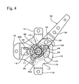
- Fig. 4 is a side view of the lever apparatus according to the embodiment of the invention, which shows the condition in which the lever is rotated upward in the full stroke from the condition in Fig. 2 .
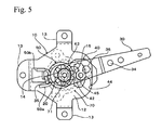
- Fig. 5 is a side view of the lever apparatus according to the embodiment of the invention, which shows the condition in which the lever is released and is returning to a neutral position from the condition in Fig. 4 .
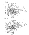
- Fig. 6 is a side view of the lever apparatus according to the embodiment of the invention, which shows the condition in which the lever is at the neutral position and the down latch portion engages with the gear.
- Fig. 7 is a side view of the lever apparatus according to the embodiment of the invention, which shows the condition in which the lever is operated upward from the condition in Fig. 6 .
- Fig. 8 is a side view of the lever apparatus according to the embodiment of the invention, which shows the condition in which the lever is further operated upward from the condition in Fig. 7 .
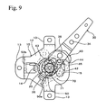
- Fig. 9 is a side view of the lever apparatus according to the embodiment of the invention, which shows the condition in which the lever is further operated upward from the condition in Fig. 8 .
- Fig. 1 shows an exploded perspective view of the embodiment
- Fig. 2 is a side view showing the condition in which the lever apparatus in Fig. 1 is assembled
- Fig. 3 is a lateral cross section of Fig. 2
- the lever apparatus includes a bracket 10, a gear 20, a lever 30, a latch 40, a return spring 50, and a snap spring 60.
- Reference numeral 70 in Figs. 1 to 3 indicates a spring brake for transmitting the movement of the lever 30 to an elevating mechanism of the seat lifter.
- the bracket 10 is formed with plural (three in the embodiment) flange portions 13 serving as a mounting portion to a seat (not shown) at the peripheral portion of a plate portion 12 having a shaft hole 11.
- a protruding piece 14 projecting toward the gear 20 is formed in the vicinity of the center flange portion 13 at an end portion of the plate portion 12.
- a guide hole 15 is formed at the other end of the plate portion 12. The guide hole 15 vertically extends along an arc coaxial with the shaft hole 11.
- the gear 20 is rotatably inserted into the shaft hole 11 of the bracket 10 from the side to which the flange portion 13 and the protruding piece 14 project.
- the gear 20 is a spur gear having rounded tooth tops and tooth spaces, and has a boss 21 at the center of an end surface.
- the gear 20 has a spring mounting body portion 22 and a gear shaft 23 coaxially formed at the other end surface of the gear 20.
- the gear shaft 23 of the gear 20 is inserted into the shaft hole 11 of the bracket 10 so as to be rotatable and so as not to be separate therefrom.
- the return spring 50 is wound around the spring mounting body portion 22 of the gear 20.
- the return spring 50 is a torsion coiled spring, and as shown in Fig. 2 , the arm portions 50a and 50b hold the protruding piece 14 of the bracket 10 and an engaging piece 35 (described later) of the lever 30.
- the boss 21 of the gear rotatably supports the lever 30.
- the lever 30 is made from a steel sheet into a plate, and has a crank-shaped bent portion 31 at the intermediate portion in the longitudinal direction.
- the left end of the lever 30 in Figs. 1 to 3 has a base end at which a shaft hole 32 is formed.
- a pin hole 33 is formed in the vicinity of the shaft hole 32, and a spring mounting hole 34 is formed in the vicinity of the bent portion 31 and in the front side thereof (right side in Figs. 1 to 3 ).
- the base end of the lever 30 is formed with the engaging piece 35, which is bent toward the bracket 10.
- the shaft hole 32 of the lever 30 is rotatably fit with the boss 21 of the gear 20.
- the engaging piece 35 of the lever 30 is located between arm portions 50a and 50b of the return spring 50 as shown in Fig. 2 , and between the protruding piece 14 of the bracket 10 and the coiled portion of the return spring 50, as shown in Fig. 3 .
- a gripping member (not shown) may be mounted at the front end of the lever 30.
- a latch pin 36 is inserted into the pin hole 33 of the lever 30 from the opposite side of the bracket 10.
- the latch pin 36 is secured to the lever 30 by means of welding, or the like.
- the latch pin 36 projects from the lever 30 toward the bracket 10, and the latch 40 is rotatably mounted to the projected portion of the latch pin 36.
- the latch 40 has a symmetrical shape like a crescent moon including a concave circumference 40a and convex circumference 40b.
- a pin hole 41 is formed at the center of the latch 40.
- a protrusion 42 is formed at the center of the concave circumference 40a.
- the ends of the latch 40 are formed into a triangle protrusion having a relatively sharp edge, and the upper end (in Figs. 1 and 2 ) is up-latch portion 43 and the lower end (in Figs. 1 and 2 ) is down-latch portion 44.
- the protrusion 42 is secured to an end of an engaging pin 45 extending toward the bracket 10 in parallel with the latch pin 36.
- the latch 40 is rotatably mounted to the bracket 10 around the latch pin 36 by inserting the latch pin 36 into the pin hole 41. In this condition, the engaging pin 45 is inserted into a guide hole 15 of the bracket 10, as shown in Fig. 3 .
- the lever 30 has a spring engaging hole 34, to which the end of the snap spring 60 is hooked. The other end of the snap spring 60 is hooked to the engaging pin 45. In Figs. 4 to 9 , description of the snap spring 60 is omitted.
- the spring brake 70 consists of an input shaft 71 formed with a spline on outer surface thereof, an output shaft 73 having a driving gear 72, and a braking mechanism 74 located between the shafts 71 and 73.
- the braking mechanism 74 prevents rotation of the output shaft 73 when a rotation torque is exerted thereto, and connects the shafts 71 and 73 and allows the rotation thereof when a rotation torque is exerted to the input shaft 71. That is, although the output shaft 73 rotates in the same direction of the input shaft 71 according to the rotation thereof, the output shaft 73 and the input shaft 71 do not rotate when the output shaft 73 is intended to rotate.
- the input shaft 71 of the spring brake 70 is fit into an internal gear 24 formed in the boss 21 of the gear 20, so that the rotation of the gear 20 is transmitted to the output shaft 73 via the input shaft 71.
- the driving gear 72 of the output shaft 73 is connected to a driving shaft which drives an elevating mechanism of a seat lifter (both not shown). The seat moves upward when the driving gear 72 is rotated in the direction indicated by the arrow A1 in Fig. 1 , and the seat moves downward when the driving gear 72 is rotated in the direction indicated by the arrow B1.
- the description of the output shaft 73 and the driving gear 72 is omitted in Fig. 3 .
- the lever 30 can be rotated upward or downward around the boss 21 of the gear 20.
- the lever 30 is returned to the approximately horizontal neutral position by the return spring 50.
- the latch 40 is then in one of two conditions in which the up-latch portion 43 engages with the gear 20 or the down-latch portion 44 engages the gear 20 according to the operation of the lever 30, and the condition is maintained by the snap spring 60.
- Fig. 2 shows the condition in which the up-latch portion 43 of the latch 40 engages with the gear 20 after the lever 30 is rotated upward.
- Fig. 6 shows the condition in which the down-latch portion 44 of the latch 40 engages with the gear 20 after the lever 30 is rotated downward.
- the lever 30 is rotated upward when the seat is moved upward, and the lever 30 is rotated downward when the seat is moved downward. The movement of the seat from the condition in Fig. 2 will be explained hereinafter.
- the lever 30 When the lever 30 is released from the hand after the lever 30 is moved in the full stroke, the lever 30 downwardly rotates by itself and returns to the neutral position by the action of the return spring 50. In this movement, the up-latch portion 43 of the latch 40 is upwardly urged to the gear 20 by the function of the snap spring 60, so that the up-latch portion 43 does not engage with the gear 20 and passes thereover. Therefore, the lever 30 can return to the neutral position shown in Fig. 2 .
- the seat can be adjusted to the required height by repeating the above-described operation. It should be noted that the load exerted by the seat is not transmitted to the input shaft 71 by the function of the braking mechanism of the spring brake 70, so that the gear 20 is not reversed when the lever 30 is released and the force for supporting the gear 20 is extracted.
- the snap spring 60 operates a snap function in which it is extended to the maximum and passes the change point thereof; it then returns to the previous condition, so that the snap spring 60 moves to the position where it maintains the condition in which the up-latch portion 43 engages with the gear 20.
- the position of the lever 30 in Fig. 8 shows the position of the change point in which the snap spring 60 is extended to the maximum.
- the lever 30 can be rotated downward from the condition in Fig. 2 since the up-latch portion 43 passes over the gear 20, and then the engaging pin 45 comes into contact with the lower edge of the guide hole 15 of the bracket 10.
- the engaging piece 35 thereof thrusts and moves upward the other arm portion 50b of the return spring 50, so that an elastic force for returning the lever 30 to the neutral position occurs. From this condition, when the lever 30 is further rotated downward opposing the elastic force of the snap spring 60, the latch 40 is rotated clockwise in Fig.
- the snap spring 60 operates a snap function in which it is extended to the maximum and passes the change point thereof; it then returns to the previous condition, so that the snap spring 60 moves to the position where it maintains the condition in which the down-latch portion 44 engages with the gear 20.
- the operated movement of the lever 30 is transmitted to the driving gear 72 of the spring brake 70, which is connected to the elevating mechanism of the seat lifter, via the latch 40 and the gear 20.
- the engagement of the latch 40 with respect to the gear 20 can be changed to the condition for normal or reverse rotation thereof according to the direction of the lever 30 by further operating the lever 30 from the condition in which the engaging pin 45 engages with the upper edge or the lower edge of the guide hole 15 of the bracket 10.
- one latch 40 enables the change of the normal rotation or reverse rotation of the gear 20. Therefore, in the embodiment, the number of the parts can be relatively reduced and the construction thereof can be simple, and problems are therefore reduced and high reliability can be obtained.
- lever apparatus of the invention is not limited to seat lifters, the lever apparatus can also be applied to various types of mechanisms in which the movement direction is changed according to the operation direction of a lever.
Landscapes
- Engineering & Computer Science (AREA)
- Aviation & Aerospace Engineering (AREA)
- Transportation (AREA)
- Mechanical Engineering (AREA)
- Seats For Vehicles (AREA)
- Mechanical Control Devices (AREA)
- Mechanical Operated Clutches (AREA)
- Transmission Devices (AREA)
Applications Claiming Priority (2)
| Application Number | Priority Date | Filing Date | Title |
|---|---|---|---|
| JP2000060464 | 2000-03-06 | ||
| JP2000060464A JP4289532B2 (ja) | 2000-03-06 | 2000-03-06 | レバー装置 |
Publications (3)
| Publication Number | Publication Date |
|---|---|
| EP1132253A2 EP1132253A2 (en) | 2001-09-12 |
| EP1132253A3 EP1132253A3 (en) | 2003-01-02 |
| EP1132253B1 true EP1132253B1 (en) | 2009-03-18 |
Family
ID=18580776
Family Applications (1)
| Application Number | Title | Priority Date | Filing Date |
|---|---|---|---|
| EP01105243A Expired - Lifetime EP1132253B1 (en) | 2000-03-06 | 2001-03-05 | Lever apparatus |
Country Status (4)
| Country | Link |
|---|---|
| US (1) | US6446527B2 (ja) |
| EP (1) | EP1132253B1 (ja) |
| JP (1) | JP4289532B2 (ja) |
| DE (1) | DE60137986D1 (ja) |
Families Citing this family (10)
| Publication number | Priority date | Publication date | Assignee | Title |
|---|---|---|---|---|
| US6666423B1 (en) * | 2002-05-31 | 2003-12-23 | Tachi-S Co., Ltd. | Ratchet-type lever mechanism for seat lifter |
| FR2841192B1 (fr) * | 2002-05-31 | 2006-01-20 | Tachi S Co | Mecanisme de levage a rochet pour dispositif de levage de siege, notamment de vehicule automobile |
| JP4471847B2 (ja) | 2005-01-04 | 2010-06-02 | 株式会社デルタツーリング | シートの高さ調節装置 |
| JP4951944B2 (ja) * | 2005-11-17 | 2012-06-13 | アイシン精機株式会社 | 車両用シートリフター装置のクラッチ装置 |
| JP5093156B2 (ja) * | 2009-03-04 | 2012-12-05 | 株式会社デンソー | 回転式アクチュエータ |
| JP5219896B2 (ja) * | 2009-03-23 | 2013-06-26 | 日新製鋼株式会社 | レバー部材およびその製造方法 |
| JP5278227B2 (ja) * | 2009-07-30 | 2013-09-04 | 株式会社今仙電機製作所 | 車両用シートの高さ調整装置 |
| KR101585263B1 (ko) | 2009-11-18 | 2016-01-13 | 주식회사다스 | 차량용 리클라이너의 작동장치 |
| DE102010020561A1 (de) * | 2010-05-14 | 2011-11-17 | Gm Global Technology Operations Llc (N.D.Ges.D. Staates Delaware) | Verstellvorrichtung zum Verstellen einer Rückenlehne eines Fahrzeugssitzes |
| JP6634250B2 (ja) * | 2015-09-16 | 2020-01-22 | 三菱電機株式会社 | 揺動装置 |
Family Cites Families (5)
| Publication number | Priority date | Publication date | Assignee | Title |
|---|---|---|---|---|
| US4538856A (en) * | 1982-09-20 | 1985-09-03 | Shiroki Kinzoku Kogyo Kabushiki Kaisha | Reclining angle adjustment device |
| DE3409144A1 (de) * | 1984-03-13 | 1985-09-19 | C. Rob. Hammerstein Gmbh, 5650 Solingen | Verstellvorrichtung mit schrittschaltmechanik |
| DE3704954C1 (en) * | 1987-02-17 | 1988-05-19 | Burger Soehne | Hand-lever-actuated step-by-step switch mechanism for forward and rearward pivoting steps in variable sequence |
| US5865285A (en) * | 1995-02-03 | 1999-02-02 | Brose Fahrzeugteile Gmbh & Co. Kg, Coburg | Manual drive operating in both directions to produce a rotary movement, more particularly for vehicle seats |
| DE19540631C2 (de) * | 1995-10-31 | 2001-06-07 | Hammerstein Gmbh C Rob | Selbstsperrende Schrittschaltmechanik für eine Verstellvorrichtung eines Fahrzeugsitzes |
-
2000
- 2000-03-06 JP JP2000060464A patent/JP4289532B2/ja not_active Expired - Fee Related
-
2001
- 2001-03-05 US US09/797,851 patent/US6446527B2/en not_active Expired - Fee Related
- 2001-03-05 DE DE60137986T patent/DE60137986D1/de not_active Expired - Lifetime
- 2001-03-05 EP EP01105243A patent/EP1132253B1/en not_active Expired - Lifetime
Also Published As
| Publication number | Publication date |
|---|---|
| EP1132253A2 (en) | 2001-09-12 |
| JP2001246968A (ja) | 2001-09-11 |
| JP4289532B2 (ja) | 2009-07-01 |
| US6446527B2 (en) | 2002-09-10 |
| DE60137986D1 (de) | 2009-04-30 |
| EP1132253A3 (en) | 2003-01-02 |
| US20010027904A1 (en) | 2001-10-11 |
Similar Documents
| Publication | Publication Date | Title |
|---|---|---|
| EP1132253B1 (en) | Lever apparatus | |
| KR100227013B1 (ko) | 자동차용 시트 리프터 | |
| JP3464634B2 (ja) | 調節可能ペダルの取付組立体 | |
| US5863098A (en) | Seat height adjusting device | |
| US6422651B1 (en) | Stepping mechanism for an automobile seat | |
| US6817264B2 (en) | Parking brake operating device for vehicle | |
| EP0776782B1 (en) | Adjustable hinge mount for seats | |
| EP0839686A2 (en) | Seat reclining device. | |
| US4616876A (en) | Rotation adjusting apparatus | |
| JP4855376B2 (ja) | ブレーキレバー調整装置 | |
| US4767158A (en) | Reclining mechanism | |
| JPH0239214A (ja) | 前後調節可能な足踏み式ペダル | |
| JP2959235B2 (ja) | ペダル装置 | |
| JP3524473B2 (ja) | ラチェット式レバー機構 | |
| JPH085898Y2 (ja) | 跳ね上げ機構付チルト式ステアリング装置 | |
| JP3466544B2 (ja) | ラチェット式レバー機構 | |
| EP0976606A1 (en) | Seat reclining system | |
| JPH0710598Y2 (ja) | ランバーサポート | |
| JP3729709B2 (ja) | コラムシフト装置の衝撃吸収機構 | |
| KR100241036B1 (ko) | 자동차시트용 리클라이너 | |
| JP3555218B2 (ja) | シートリクライニング装置 | |
| KR200299034Y1 (ko) | 자동차 스티어링 샤프트의 틸팅장치 | |
| JP2000255294A (ja) | シートリフターおよびラチェット式レバー機構 | |
| JPS62103257A (ja) | メモリ−機構付チルトステアリング装置 | |
| JPH0412273Y2 (ja) |
Legal Events
| Date | Code | Title | Description |
|---|---|---|---|
| PUAI | Public reference made under article 153(3) epc to a published international application that has entered the european phase |
Free format text: ORIGINAL CODE: 0009012 |
|
| AK | Designated contracting states |
Kind code of ref document: A2 Designated state(s): AT BE CH CY DE DK ES FI FR GB GR IE IT LI LU MC NL PT SE TR |
|
| AX | Request for extension of the european patent |
Free format text: AL;LT;LV;MK;RO;SI |
|
| PUAL | Search report despatched |
Free format text: ORIGINAL CODE: 0009013 |
|
| AK | Designated contracting states |
Kind code of ref document: A3 Designated state(s): AT BE CH CY DE DK ES FI FR GB GR IE IT LI LU MC NL PT SE TR |
|
| AX | Request for extension of the european patent |
Free format text: AL;LT;LV;MK;RO;SI |
|
| 17P | Request for examination filed |
Effective date: 20030312 |
|
| AKX | Designation fees paid |
Designated state(s): DE FR GB |
|
| 17Q | First examination report despatched |
Effective date: 20070608 |
|
| GRAP | Despatch of communication of intention to grant a patent |
Free format text: ORIGINAL CODE: EPIDOSNIGR1 |
|
| GRAS | Grant fee paid |
Free format text: ORIGINAL CODE: EPIDOSNIGR3 |
|
| GRAA | (expected) grant |
Free format text: ORIGINAL CODE: 0009210 |
|
| AK | Designated contracting states |
Kind code of ref document: B1 Designated state(s): DE FR GB |
|
| REG | Reference to a national code |
Ref country code: GB Ref legal event code: FG4D |
|
| REF | Corresponds to: |
Ref document number: 60137986 Country of ref document: DE Date of ref document: 20090430 Kind code of ref document: P |
|
| RIN2 | Information on inventor provided after grant (corrected) |
Inventor name: NAKAMURA, TAKESHI Inventor name: MASUDA, KOU |
|
| PLBE | No opposition filed within time limit |
Free format text: ORIGINAL CODE: 0009261 |
|
| STAA | Information on the status of an ep patent application or granted ep patent |
Free format text: STATUS: NO OPPOSITION FILED WITHIN TIME LIMIT |
|
| 26N | No opposition filed |
Effective date: 20091221 |
|
| PGFP | Annual fee paid to national office [announced via postgrant information from national office to epo] |
Ref country code: FR Payment date: 20130325 Year of fee payment: 13 Ref country code: DE Payment date: 20130227 Year of fee payment: 13 Ref country code: GB Payment date: 20130228 Year of fee payment: 13 |
|
| REG | Reference to a national code |
Ref country code: DE Ref legal event code: R119 Ref document number: 60137986 Country of ref document: DE |
|
| GBPC | Gb: european patent ceased through non-payment of renewal fee |
Effective date: 20140305 |
|
| REG | Reference to a national code |
Ref country code: FR Ref legal event code: ST Effective date: 20141128 |
|
| REG | Reference to a national code |
Ref country code: DE Ref legal event code: R119 Ref document number: 60137986 Country of ref document: DE Effective date: 20141001 |
|
| PG25 | Lapsed in a contracting state [announced via postgrant information from national office to epo] |
Ref country code: FR Free format text: LAPSE BECAUSE OF NON-PAYMENT OF DUE FEES Effective date: 20140331 Ref country code: DE Free format text: LAPSE BECAUSE OF NON-PAYMENT OF DUE FEES Effective date: 20141001 Ref country code: GB Free format text: LAPSE BECAUSE OF NON-PAYMENT OF DUE FEES Effective date: 20140305 |