EP1122094B1 - Fahrradnabe - Google Patents
Fahrradnabe Download PDFInfo
- Publication number
- EP1122094B1 EP1122094B1 EP00310980A EP00310980A EP1122094B1 EP 1122094 B1 EP1122094 B1 EP 1122094B1 EP 00310980 A EP00310980 A EP 00310980A EP 00310980 A EP00310980 A EP 00310980A EP 1122094 B1 EP1122094 B1 EP 1122094B1
- Authority
- EP
- European Patent Office
- Prior art keywords
- brake
- hub
- tubular member
- frictional
- bicycle
- Prior art date
- Legal status (The legal status is an assumption and is not a legal conclusion. Google has not performed a legal analysis and makes no representation as to the accuracy of the status listed.)
- Expired - Lifetime
Links
Images


Classifications
-
- B—PERFORMING OPERATIONS; TRANSPORTING
- B60—VEHICLES IN GENERAL
- B60B—VEHICLE WHEELS; CASTORS; AXLES FOR WHEELS OR CASTORS; INCREASING WHEEL ADHESION
- B60B27/00—Hubs
- B60B27/0047—Hubs characterised by functional integration of other elements
-
- B—PERFORMING OPERATIONS; TRANSPORTING
- B60—VEHICLES IN GENERAL
- B60B—VEHICLE WHEELS; CASTORS; AXLES FOR WHEELS OR CASTORS; INCREASING WHEEL ADHESION
- B60B27/00—Hubs
- B60B27/0047—Hubs characterised by functional integration of other elements
- B60B27/0063—Hubs characterised by functional integration of other elements the element being a brake caliper mount
-
- B—PERFORMING OPERATIONS; TRANSPORTING
- B60—VEHICLES IN GENERAL
- B60B—VEHICLE WHEELS; CASTORS; AXLES FOR WHEELS OR CASTORS; INCREASING WHEEL ADHESION
- B60B27/00—Hubs
- B60B27/0078—Hubs characterised by the fixation of bearings
-
- B—PERFORMING OPERATIONS; TRANSPORTING
- B60—VEHICLES IN GENERAL
- B60B—VEHICLE WHEELS; CASTORS; AXLES FOR WHEELS OR CASTORS; INCREASING WHEEL ADHESION
- B60B27/00—Hubs
- B60B27/02—Hubs adapted to be rotatably arranged on axle
- B60B27/023—Hubs adapted to be rotatably arranged on axle specially adapted for bicycles
- B60B27/026—Hubs adapted to be rotatably arranged on axle specially adapted for bicycles comprising quick release devices
-
- B—PERFORMING OPERATIONS; TRANSPORTING
- B62—LAND VEHICLES FOR TRAVELLING OTHERWISE THAN ON RAILS
- B62J—CYCLE SADDLES OR SEATS; AUXILIARY DEVICES OR ACCESSORIES SPECIALLY ADAPTED TO CYCLES AND NOT OTHERWISE PROVIDED FOR, e.g. ARTICLE CARRIERS OR CYCLE PROTECTORS
- B62J6/00—Arrangement of optical signalling or lighting devices on cycles; Mounting or supporting thereof; Circuits therefor
- B62J6/06—Arrangement of lighting dynamos or drives therefor
- B62J6/12—Dynamos arranged in the wheel hub
Definitions
- the present invention is directed to wheel hubs for bicycles and, more particularly, to a wheel hub that is capable of housing both a generator mechanism and a brake force adjusting mechanism.
- a conventional bicycle hub comprises a hub axle detachably and nonrotatably mounted in a bicycle fork (frame), a tubular hub shell (outer shell) rotatably mounted on the hub axle, and bearings for rotatably supporting the hub shell on the hub axle.
- a pair of external hub flanges are formed at the two ends of the hub shell to allow wheel spokes to be attached to the hub shell.
- the hub shell contains either a generator mechanism or a brake force adjusting mechanism, but not both. It would be convenient to combine such power generating and brake force adjusting functions in a single bicycle wheel.
- attempts to endow a single wheel with both these functions result in the use of two bicycle hubs, each provided with one of the aforementioned functions and configured such that a pair of left and right hub flanges provided at the two ends of the hub shell are attached to wheel spokes in the manner described above. For this reason, adopting one of the hubs as the bicycle hub makes it impossible to attach the other bicycle hub and leaves no choice but to select either the generating function or the brake force adjusting function.
- Another convenient feature would be a bicycle frame with a brake for restricting the relative rotation of the hub shell and the hub axle of a bicycle hub when this hub shell contains a generator mechanism.
- a structure in which the hub shell and the structural members constituting the brake are directly or indirectly connected together is commonly adopted for brake mounting, and meshing mechanisms are often adopted for such connection.
- meshing mechanism is adopted in this manner, appropriate materials and hardening treatments must be selected for the entire hub shell, thus resulting in higher manufacturing costs.
- a bicycle hub according to the preamble of claims 1 and 13 is known from JP 10001081.
- a bicycle hub in accordance with Claim 1 there is provided a bicycle hub in accordance with Claim 13.
- a bicycle hub in accordance with Claim 13 there is provided a bicycle hub in accordance with Claim 13.
- a preferred embodiment of the present invention provides a bicycle hub wherein both a generator mechanism and a brake force adjusting mechanism are disposed within the hub shell, a bicycle hub includes a hub axle and a hub shell including a first tubular member having a first hub flange secured thereto and a separate second tubular member having a second hub flange secured thereto. Bearings are disposed between the hub shell and the hub axle for rotatably supporting the first tubular member and the second tubular member relative to the hub axle.
- a generator mechanism is housed in the first tubular member and adapted to generate electricity by rotation of the first tubular member relative to the hub axle
- a brake force adjusting mechanism is housed in the second tubular member and adapted to limit a maximum damping force of a brake.
- the generator mechanism includes an inside stator retained to the hub axle and an outside rotor that rotates in response to rotation of the first tubular member.
- the brake force adjusting mechanism includes a brake force receiving member rotatably mounted relative to the hub axle for receiving a braking force from a brake mechanism and a frictional coupler for forming a frictional link between the second tubular member and the brake force receiving member.
- the frictional coupler may include a first frictional member nonrotatably coupled relative to the brake force receiving member, a second frictional member nonrotatably coupled relative to the second tubular member in a facing arrangement with the first frictional member, and a biasing mechanism for biasing the first frictional member and the second frictional member toward each other.
- a further preferred embodiment of the invention provides a bicycle hub which includes a hub axle and a hub shell including a first tubular member having a first hub flange secured thereto, a separate second tubular member having a second hub flange secured thereto, and a brake coupling member for coupling the second tubular member to a brake device.
- the second tubular member is harder than the first tubular member.
- Bearings are disposed between the hub shell and the hub axle for rotatably supporting the first tubular member and the second tubular member relative to the hub axle, and a generator mechanism is housed in the first tubular member and is adapted to generate electricity by rotation of the first tubular member relative to the hub axle.
- a brake force adjusting mechanism adapted to limit a maximum damping force of a brake may be housed in the second tubular member.
- the structure of the generator mechanism or brake force adjusting mechanism may be similar to the corresponding mechanisms noted above, or they may be different depending upon the application.
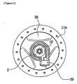
- Fig. 1 is a side view of a bicycle 101 that incorporates a particular embodiment of a front bicycle hub 1 according to the present invention.
- the bicycle 101 comprises a frame 102 including a front wheel fork 98, a handle 104, a drive unit 105 (composed of a chain, pedals, and the like), a front wheel 106 having spokes 99, and a rear wheel 107.
- the front hub 1 is attached to the front wheel fork 98 and to the front wheel 106 of the bicycle 101. More specifically, the front hub 1 is fixed to the front wheel fork 98 on the right and left sides of a hub axle 10, and spokes 99 are fixed to two hub flanges 11a and 12a.
- the two ends of the hub axle 10 are fixed by adjustment nuts 2 or cam levers 3 to the end portions of the front wheel fork 98.
- the axis O_O shown is the axis of rotation of the front wheel 106 of the bicycle.
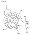
- the front hub 1 comprises the hub axle 10, a first tubular member 11, a second tubular member 12, two bearings 13 and 14, a dynamo (generator mechanism) 30, and a brake modulator (brake force adjusting mechanism) 40.
- a roller brake 80 is coupled to the left side of second tubular member 12 for applying a braking force to first tubular member 11 and second tubular member 12.
- Dynamo 30 allows generated power to be fed to the headlight, taillight, and the like.
- Brake modulator 40 absorbs excessive braking force (rotation damping force) produced by the roller brake 80, thereby performing an anti-lock function for front wheel 106. Power generated by the dynamo 30 can be drawn from a connector 39 shown in Figs. 3 and 4.
- first tubular member 11 serves as an enclosure for the dynamo 30.
- first tubular member 11 is formed from aluminum alloy die cast Type 5 (ADC5).
- ADC5 aluminum alloy die cast Type 5
- first tubular member 11 comprises a first annular hub flange 11a, a first cylindrical component 11b, an annular sloping component 11c, and a mating tubular component 11d.
- First hub flange 11a is provided with a plurality of openings that correspond to the diameter of the spokes 99, and the openings are arranged at regular intervals in the circumferential direction.
- the spokes 99 are fixed in these openings such that the inner ends of the spokes are disposed on the right.
- the first cylindrical component 11b is a cylindrical section extending from the internal peripheral end of the first hub flange 11a to the left side.
- a cap 36 of the dynamo 30 is mounted on the internal peripheral surface of the first cylindrical component 11b.
- the annular sloping component 11c extends radially inwardly from the left end of the first cylindrical component 11b, and the cylindrical mating tubular component 11d extends to the left from the inner peripheral end of the annular sloping component 11c.
- the second tubular member 12 serves as an enclosure for the brake modulator 40.
- second tubular member 12 is forged from an aluminum alloy, and it is heat-treated to a hardness of HRB 55 or greater. As a result, second tubular member 12 is made harder than the first tubular member 11.
- second tubular member 12 comprises a second annular hub flange 12a, a second cylindrical component 12b extending to the right from the inner peripheral end of the second hub flange 12a, and a cylindrical mating tubular component 12c extending to the right of second cylindrical component 12b.
- the tubular members 11 and 12 are rendered nonrotatable relative to each other by causing the inner peripheral surface of the mating tubular component 12c to engage the outer peripheral surface of the mating tubular component 11d of the first tubular member 11.
- the outer peripheral portion of the second hub flange 12a is provided with a plurality of openings that correspond to the diameter of the spokes 99, wherein the openings are arranged at regular intervals in the circumferential direction.
- the spokes 99 are fixed in these openings such that the inner ends of the spokes are disposed on the left side as shown in Fig. 2.
- Serrations or splines 12d for engaging a plurality of complementary splines on the hub-side friction plate 43 of the brake modulator 40 are provided to the inner peripheral surface of the second cylindrical component 12b.
- the diameter of the second cylindrical component 12b of the second tubular member 12 is less than the diameter of the first cylindrical component 11b of the first tubular member 11 because this arrangement is sufficient for accommodating the brake modulator 40.
- the first tubular member 11 and the second tubular member 12 constitute the outer shell of the front hub 1.
- the bearing 13 comprises a plurality of balls 13a, a ball race 13b for supporting these balls 13a, and a cup 13c.
- the ball race 13b is fixed to the hub axle 10
- the cup 13c is fixed to the inner peripheral portion of the cap 36 of dynamo 30.
- the bearing 13 is configured such that the cap 36 of the dynamo 30 and the first tubular member 11 mounted on the cap 36 are rotatably supported on the hub axle 10.
- the bearing 14 comprises a plurality of balls 14a, a ball race 14b for supporting these balls 14a, and an annular cup 41 of the brake modulator 40.
- the ball race 14b is fixed to the hub axle 10, and the bearing 14 rotatably supports the annular cup 41 and the second tubular member 12 on the hub axle 10.
- the dynamo 30 comprises an inside stator and an outside rotor.
- the inside stator primarily comprises two stator yokes 31 and 32, a bobbin 34 with a wound coil 33, and a tubular core yoke 35 fixed to hub axle 10. When assembled together, the stator yokes 31 and 32, the bobbin 34, and the tubular core yoke 35 form a unified inside stator.
- the stator yokes 31 and 32 consist of disk portions and claws. Fourteen claws are formed at regular intervals in the circumferential direction, and these claws extend along the O_O axis from the outer peripheral edges of the disk portions of the stator yokes 31 and 32. When assembled, the claws of the two stator yokes 31 and 32 are spaced at regular intervals and are aligned at regular intervals in the circumferential direction. Permanent magnets 37 are positioned facing each claw at radially external positions in relation to the claws. In addition, the disk portions of the stator yokes 31 and 32 have round holes for accommodating the hub axle 10, and slits extending radially outward from the round holes.
- the bobbin 34 is an annular member made of resin. Grooves for winding and supporting the coil 33 are formed on the external peripheral portion thereof, and stepped notches for mating with the tubular core yoke 35 are formed in the internal peripheral portion thereof.
- the tubular core yoke 35 composed of 12 split-piece assemblies stacked parallel to the direction of the O_O axis in this embodiment, is mounted on the inside of the bobbin 34 in engagement with the notches in the internal peripheral portion of the bobbin 34.
- Each of the split-piece assemblies constituting the tubular core yoke 35 is obtained by fitting together four separate pieces shaped as rectangular sheets. When the twelve split-piece assemblies are fitted into the notches in the internal peripheral portion of the bobbin 34, these split-piece assemblies form the tubular core yoke 35.
- This core yoke has an internal space that has a square cross section and allows the hub axle 10 to pass through the center thereof.
- the outside rotor is formed by the aforementioned first tubular member 11 and cap 36, and the resulting assembly is rotatably supported on the hub axle 10 by the bearing 13.
- the cap 36 is provided with a permanent magnet 37 which is composed of four magnet pieces divided at regular intervals in the circumferential direction.
- the permanent magnet 37 is magnetized such that the N-poles and S_poles thereof are disposed alternately at regular intervals, and each of the resulting 28 poles lies opposite a claw of the stator yokes 31 and 32.
- the brake modulator 40 which is a mechanism disposed inside the second cylindrical component 12b of the second tubular member 12, comprises the annular cup (brake-side member) 41, three brake-side friction plates (first frictional members) 42, three hub-side friction plates (second frictional members) 43, a conical spring washer 44, and a nut 45.
- the annular cup 41 is formed from carbon steel that is carburized, quenched, and tempered, and it primarily comprises a circular disk component 41a, a left projection (ball race) 41b, and an inside tubular component 41c.
- the outer peripheral portion of the circular disk component 41a fits into the annular notch provided to the left inner peripheral end of the second tubular member 12.
- the left projection 41b is a cylindrical section extending from the circular disk component 41a to the left, and the outer peripheral portion at the end thereof is provided with an 18_tooth serrated portion 41d.
- the inside tubular component 41c is a tubular component extending to the right from the inner peripheral end of the circular disk component 41a, and the outer peripheral portion thereof is provided with three notches 41e.
- the three brake-side friction plates 42 are washers with three inner peripheral projections that fit into the three notches 41e of the annular cup 41. These brake-side friction plates 42 are disposed between the three hub-side friction plates 43 and between the conical spring washer 44 and the hub-side friction plates 43 on the right side.
- the outer peripheral portions of the three hub-side friction plates 43 are provided with a plurality of teeth for engaging the serrations 12d on the inner peripheral portion of the second tubular member 12.
- These hub-side friction plates 43 are disposed between the three brake-side friction plates 42 and between the circular disk component 41a of the annular cup 41 and the left-most brake-side friction plates 42.
- the conical spring washer 44 urges the friction plates 42 and 43 toward the circular disk component 41a of the annular cup 41 in a state in which the right side thereof is pressed against the nut 45, the friction plates 42 and 43 are held between each other, and torque is transmitted through them.
- the nut 45 is fixed by being screwed onto the tip (right end) of the inside tubular component 41c of the annular cup 41.
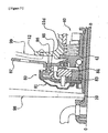
- the roller brake 80 comprises a casing 81, a rocking member 82, an annular cam 83, a plurality of rollers 84, brake shoes 85, a brake drum 86, and a cooling fin 87.
- the roller brake 80 is set on the hub axle 10 such that the end portion of the brake drum 86 meshes with the serrated portion 41d of the annular cup 41 of the brake modulator 40, and the attachment component 81a of the casing 81 is fixed ti the front wheel fork 98.
- the outer cable of a brake wire 109 (see Fig. 1) is secured in the outer holder 81b of the casing 81, and the inner cable is connected to the connector 82a provided to the rocking member 82.
- the rocking member 82 is pivotably supported relative to the casing 81 and pivots relative to the casing 81 when the inner cable of the brake wire 109 is pulled or released.
- the annular cam 83 which is connected to the rocking member 82, rotates through a prescribed angle in conformity with the pivoting of the rocking member 82.
- the rollers 84 are disposed at the outer peripheral surface of the annular cam 83, and they move radially in accordance with the rotation of the annular cam 83.
- the rollers 84 are housed in a roller case for suppressing any shifting in position in the circumferential direction.
- a plurality of brake shoes 85 extend in the circumferential direction around the rollers 84, and these shoes are pushed radially outwardly or retracted inwardly in accordance with the radial movement of the rollers 84.
- the brake shoes 85 are prevented from rotating in the circumferential direction.
- the outer peripheral portion of brake drum 86 is disposed around the outside of the brake shoes 85, and the inner peripheral portion of brake drum 86 is provided with teeth for meshing with the serrated portion 41d of the annular cup 41 of the brake modulator 40.
- the brake drum 86 can rotate in relation to the casing 81.
- the cooling fin 87 is a large annular fin in contact with the outer peripheral surface of the brake drum 86, steeply widening therefrom toward its outer periphery.
- the cooling fin 87 acts to prevent the brake drum 86 or the components inside the casing 81 from overheating, thus allowing the grease inside the casing 81 to perform stably for a long time and preventing the brake from seizing during long descents.
- rotating the permanent magnet 37 and making it pass around the individual claws of the stator yokes 31 and 32 create two repeating states: a first state in which the stator yoke 31 is an N_pole and the stator yoke 32 is an S_pole, and a second state in which the stator yoke 31 is an S_pole and the stator yoke 32 is an N_pole.
- An alternating magnetic flux is thus generated in the direction of the O_O axis in the tubular core yoke 35 magnetically linking the two yokes 31 and 32 with each other, thus inducing current in the coil 33.
- the rocking member 82 of the roller brake 80 is pivoted when the rider pulls on the inner cable of the brake wire 109 by actuating the brake. This causes the annular cam 83 to rotate and the rollers 84 to move radially outwardly. As this happens, the brake shoes 85 are pushed outwardly and press against the brake drum 86. The rotation of the brake drum 86 is thereby impeded.
- the rotation damping force (braking force) exerted by the brake drum 86 is transmitted via the serrated portions 41d to the annular cup 41 and to the brake modulator 40.
- the damped rotation is transmitted via the brake-side friction plates 42 and the hub-side friction plates 43 to the second tubular member 12.
- a rotation damping force also acts on the first tubular member 11, and braking is applied to the rotation of the front wheel 106 fixed to the hub flanges 11a and 12a with the aid of the spokes 99.
- a conventional bicycle hub is configured such that a dynamo or a brake modulator is disposed inside a tubular hub shell (outer shell) provided with a pair of hub flanges at the two ends thereof, so mounting either of these makes it impossible to mount the other.
- the front hub 1 of the present embodiment is configured such that the tubular member 11 or 12 containing a dynamo 30 or a brake modulator 40 is attached with the aid of a single hub flange 11a or 12a to the spokes 99 whose inner ends are disposed on the left or right. It is therefore possible to provide a single bicycle wheel (front wheel 106) attached to a single type of wheel spoke with both the dynamo 30 and the brake modulator 40.
- the first tubular member 11 is made of aluminum alloy die cast Type 5 (ADC5), and the second tubular member 12 is forged from an aluminum alloy.
- the second tubular member 12 alone is heat-treated, and the hardness of the second tubular member 12 is set to HRB 55 or greater.
- the second tubular member 12 is harder than the first tubular member 11.
- the rotation damping force exerted by the brake on the bicycle wheel is transmitted from the brake-side member to the second tubular member via the first and second frictional members.
- the second tubular member must have sufficient hardness to mesh with the second frictional member and to transmit the rotation damping force.
- the first tubular member is primarily designed for accommodating power generation members and does not need to be as hard as the second tubular member, which transmits the rotation damping force from the brake by means of meshing.
- the second tubular member is allowed to fulfill its function and the first tubular member is made less expensive as a result of the fact that the hardness of the material for the second tubular member is set above the hardness of the material for the first tubular member in accordance with the present invention.
- the present invention was adapted to a front hub 1 for supporting the front wheel 106, but the present invention is also applicable to a bicycle hub for supporting a rear wheel 107.
- the mating portion (portion corresponding to the serrations 41d) of the brake modulator 40 can be modified to allow various brakes (such as those defined in Japanese Industrial Standards (JIS) D_9414) for damping hub components to be mounted.
- a meshing-type brake modulator can be adopted in addition to the frictional brake modulator 40 used in the above-described embodiment.
- Such a meshing-type brake modulator comprises a meshing-type clutch and a spring designed to engage and urge the clutch and to set the torque when the clutch is disengaged.
Claims (22)
- Fahrradnabe, umfassend:eine Nabenachse (10);ein Nabengehäuse;Lager (13, 14), welche zwischen dem Nabengehäuse und der Nabenachse (10) angeordnet sind, um das Nabengehäuse in Bezug zur Nabenachse (10) zu lagern; undeinen Generatormechanismus (30), der vom Nabengehäuse umhaust und so gestaltet ist, dass er durch Drehung des Nabengehäuses relativ zur Nabenachse (10) Elektrizität erzeugt;
dadurch gekennzeichnet, dass
das Nabengehäuse umfasst:ein erstes rohrförmiges Teil (11), welches einen ersten daran befestigten Nabenflansch (11a) aufweist; undein separates zweites rohrförmiges Teil (12), welches einen zweiten daran befestigten Nabenflansch (12a) aufweist;wobei der Generatormechanismus (30) von einem ersten rohrförmigen Teil (11) umhaust ist, unddie Fahrradnabe weiterhin einen Bremskraftjustiermechanismus (40) umfasst, der von dem zweiten rohrförmigen Teil (12) umhaust und so gestaltet ist, dass er eine maximale Dämpfungskraft einer Bremse (80) begrenzt. - Fahrradnabe nach Anspruch 1, bei welcher der Generatormechanismus (30) umfasst:einen innenseitigen Stator, der an der Nabenachse (10) gehalten ist, undeinen außenseitigen Rotor, der sich in Reaktion auf die Drehung des ersten rohrförmigen Teiles (11) dreht; undbei welcher der Bremskraftjustiermechanismus (40) umfasst:ein Bremskraftaufnahmeteil, das in Bezug zur Nabenachse (10) drehbar befestigt ist, um eine Bremskraft von einem Bremsmechanismus (80) aufzunehmen; undeine Reibkupplung zur Bildung einer Reibungsverbindung zwischen dem zweiten rohrförmigen Teil (12) und dem Bremskraftaufnahmeteil.
- Fahrradnabe nach Anspruch 2, bei welcher ein Material, welches das zweite rohrförmige Teil (12) bildet, härter ist als ein Material, welches das erste rohrförmige Teil (11) bildet, und bei welchem die Reibkupplung umfasst:ein erstes Reibteil (42), welches in Bezug zum Bremskraftaufnahmeteil nicht drehbar gekoppelt ist; undein zweites Reibteil (43), welches in Bezug zum zweiten rohrförmigen Teil (12) nicht drehbar und in gegenüberliegender Anordnung zum ersten Reibteil (42) gekoppelt ist.
- Fahrradnabe nach Anspruch 3, bei welcher mindesten eines von dem ersten Reibteil (42) und dem zweiten Reibteil (43) in Bezug zum entsprechenden Bremskraftaufnahmeteil und zweiten rohrförmigen Teil (12) axial bewegbar ist; und bei welcher die Reibkupplung weiterhin einen Vorspannungsmechanismus (44) umfasst, um das erste Reibteil (42) und das zweite Reibteil (43) zueinander vorzuspannen.
- Fahrradnabe nach einem jeden der Ansprüche 2 bis 4, bei welchen das Bremskraftaufnahmeteil einen gezahnten Bereich (41d) aufweist, um das Bremskraftaufnahmeteil mit dem Bremsmechanismus (80) zu koppeln.
- Fahrradnabe nach einem jeden der Ansprüche 2 bis 5, bei welcher der Bremsmechanismus (80) mit dem Bremskraftaufnahmeteil gekoppelt ist.
- Fahrradnabe nach Anspruch 6, bei welcher der Bremsmechanismus (80) eine Bremstrommel (86) umfasst, die nicht drehbar mit dem Bremskraftaufnahmeteil gekoppelt ist.
- Fahrradnabe nach Anspruch 7, bei welchem der Bremsmechanismus (80) weiterhin umfasst:eine Bremsbacke (85), die radial einwärts der Bremstrommel (86) angeordnet ist, zwecks Reibkontakt mit der Bremstrommel (86);einen Nocken (83), der in Bezug zur Nabenachse (10) drehbar radial einwärts der Bremsbacke (85) befestigt ist; undeine Mehrzahl von Rollen (84), die zwischen einer radialen Außenfläche des Nockens (83) und einer radialen Innenfläche der Bremsbacke (85) zwecks Bewegung der Bremsbacke (85) zur Bremstrommel (86) in Reaktion auf die Drehung des Nockens (83) angeordnet ist.
- Fahrradnabe nach einem jeden der Ansprüche 2 bis 8, bei welcher die Lager umfassen:ein erstes Lager (14) zur drehbaren Lagerung des ersten rohrförmigen Teiles (11) in Bezug zur Nabenachse (10); undein zweites Lager (13), welches zwischen dem Bremskraftaufnahmeteil undder Nabenachse (10) angeordnet ist, um das zweite rohrförmige Teil (12) in Bezug zur Nabenachse (10) drehbar zu lagern.
- Fahrradnabe nach einem jeden der vorhergehenden Ansprüche, bei welcher das erste rohrförmige Teil (11) einen anderen Außendurchmesser aufweist, als das zweite rohrförmige Teil (12).
- Fahrradnabe nach einem jeden der vorhergehenden Ansprüche, bei welcher das erste rohrförmige Teil (11) am Ort des Generatormechanismus (30) einen anderen Außendurchmesser aufweist als das zweite rohrförmige Teil (12) am Ort des Bremskraftjustiermechanismus (40).
- Fahrradnabe nach einem jeden der vorhergehenden Ansprüche, bei welcher das erste rohrförmige Teil (11) aus einem Material gebildet ist, dass sich vom Material unterscheidet, aus welchem das zweite rohrförmige Teil (12) gebildet ist.
- Fahrradnabe, umfassend:eine Nabenachse (10);ein Nabengehäuse;Lager, welche zwischen dem Nabengehäuse und der Nabenachse (10) angeordnet sind, um das Nabengehäuse in Bezug zur Nabenachse (10) drehbar zu lagern; undeinen Generatormechanismus (30), welcher vom Nabengehäuse umhaust undso gestaltet ist, dass er durch Drehung des Nabengehäuses in Bezug zur Nabenachse (10) Elektrizität erzeugt;
dadurch gekennzeichnet, dass
das Nabengehäuse umfasst:ein erstes rohrförmiges Teil (11), welches einen ersten daran befestigten Nabenflansch (11a) aufweist; undein separates zweites rohrförmiges Teil (12), welches einen zweiten daran befestigten Nabenflansch (12a) aufweist;wobei das zweite rohrförmige Teil (12) härter ist als das erste rohrförmige Teil (11); undder Generatormechanismus (30) vom ersten rohrförmigen Teil (11) umhaust ist; unddas Nabengehäuse weiterhin ein Bremskupplungsteil umfasst, welches von dem zweiten rohrförmigen Teil (12) umhaust und so gestaltet ist, dass es das zweite rohrförmige Teil (12) mit der Bremsvorrichtung (80) koppelt. - Fahrradnabe nach Anspruch 13, welche weiterhin einen Bremskraftjustiermechanismus (40) umfasst, der von dem zweiten rohrförmigen Teil (12) umhaust und so gestaltet ist, dass er eine maximale Dämpfungskraft einer Bremse (80) begrenzt.
- Fahrradnabe nach Anspruch 14, bei welcher der Generatormechanismus (30) umfasst:einen innenseitigen Stator, der an der Nabenachse (10) gehalten ist; undeinen außenseitigen Rotor, welcher sich in Reaktion auf die Drehung des ersten rohrförmigen Teiles (11) dreht; undbei welcher der Bremskraftjustiermechanismus (40) umfasst:ein Bremskraftaufnahmeteil, welches das Bremskupplungsteil enthält, das drehbar in Bezug zur Nabenachse (10) befestigt ist, um eine Bremskraft vom Bremsmechanismus (80) aufzunehmen; undeine Reibkupplung zur Bildung einer Reibverbindung zwischen dem zweiten rohrförmigen Teil (12) und dem Bremskraftaufnahmeteil.
- Fahrradnabe nach Anspruch 15, bei welcher die Reibkupplung umfasst:ein erstes Reibteil (42), welches in Bezug zum Bremskraftaufnahmeteil nicht drehbar gekoppelt ist; undein zweites Reibteil (43), welches in Bezug zum zweiten rohrförmigen Teil (12) nicht drehbar und in gegenüberliegender Anordnung zum ersten Reibteil (42) gekoppelt ist.
- Fahrradnabe nach Anspruch 16, bei welcher mindesten eines von dem ersten Reibteil (42) und dem zweiten Reibteil (43) in Bezug zum zugehörigen Bremskraftaufnahmeteil und zum zweiten rohrförmigen Teil (12) axial beweglich ist; und bei welchem die Reibkupplung weiterhin einen Vorspannungsmechanismus (44) umfasst, um das erste Reibteil (42) und das zweite Reibteil (43) zueinander vorzuspannen.
- Fahrradnabe nach einem jeden der Ansprüche 15 bis 17, bei welcher das Bremskraftaufnahmeteil einen gezahnten Bereich (41d) zur Kopplung des Bremskraftaufnahmeteiles mit dem Bremsmechanismus (80) umfasst.
- Fahrradnabe nach einem jeden der Ansprüche 15 bis 18, welche weiterhin einen Bremsmechanismus (80) umfasst, der mit dem Bremskraftaufnahmeteil gekoppelt ist.
- Fahrradnabe nach einem jeden der Ansprüche 15 bis 19, bei welcher der Bremsmechanismus (80) eine Bremstrommel (86) umfasst, die nicht drehbar mit dem Bremskraftaufnahmeteil gekoppelt ist.
- Fahrradnabe nach Anspruch 20, bei welcher der Bremsmechanismus (80) weiterhin umfasst:eine Bremsbacke (85) die radial einwärts der Bremstrommel (86) zwecks Reibkontakt mit der Bremstrommel (86) angeordnet ist;einen Nocken (83), der in Bezug zur Nabenachse (10) drehbar radial einwärts der Bremsbacke (85) befestigt ist; undeine Mehrzahl von Rollen (84), die zwischen einer radialen Außenfläche des Nockens (83) und einer radialen Innenfläche der Bremsbacke (85) zwecks Bewegung der Bremsbacke (85) zur Bremstrommel (86) in Reaktion auf die Drehung des Nockens (83) angeordnet ist.
- Fahrradnabe nach einem jeden der Ansprüche 15 bis 21, bei welcher die Lager umfassen:ein erstes Lager (14) zur drehbaren Lagerung des ersten rohrförmigen Teiles (11) in Bezug zur Nabenachse (10); undein zweites Lager (13), welches zwischen dem Bremskraftaufnahmeteil und der Nabenachse (10) angeordnet ist, um das zweite rohrförmige Teil (12) in Bezug zur Nabenachse (10) drehbar zu lagern.
Applications Claiming Priority (2)
| Application Number | Priority Date | Filing Date | Title |
|---|---|---|---|
| JP2000021609 | 2000-01-31 | ||
| JP2000021609A JP3477134B2 (ja) | 2000-01-31 | 2000-01-31 | 自転車用ハブ |
Publications (3)
| Publication Number | Publication Date |
|---|---|
| EP1122094A2 EP1122094A2 (de) | 2001-08-08 |
| EP1122094A3 EP1122094A3 (de) | 2003-07-16 |
| EP1122094B1 true EP1122094B1 (de) | 2006-02-01 |
Family
ID=18547995
Family Applications (1)
| Application Number | Title | Priority Date | Filing Date |
|---|---|---|---|
| EP00310980A Expired - Lifetime EP1122094B1 (de) | 2000-01-31 | 2000-12-08 | Fahrradnabe |
Country Status (6)
| Country | Link |
|---|---|
| US (1) | US6559564B1 (de) |
| EP (1) | EP1122094B1 (de) |
| JP (1) | JP3477134B2 (de) |
| CN (1) | CN1217807C (de) |
| DE (1) | DE60025798T2 (de) |
| TW (1) | TW453955B (de) |
Families Citing this family (44)
| Publication number | Priority date | Publication date | Assignee | Title |
|---|---|---|---|---|
| TW507258B (en) * | 2000-02-29 | 2002-10-21 | Semiconductor Systems Corp | Display device and method for fabricating the same |
| US6703716B2 (en) * | 2001-10-17 | 2004-03-09 | Meng-Yu Liu | Permanent magnet generator for bicycle light operation |
| JP3720002B2 (ja) | 2002-06-11 | 2005-11-24 | 株式会社シマノ | 自転車用ハブブレーキ装置 |
| JP3740092B2 (ja) * | 2002-06-11 | 2006-01-25 | 株式会社シマノ | 自転車用ハブブレーキ装置 |
| JP3703780B2 (ja) * | 2002-06-11 | 2005-10-05 | 株式会社シマノ | 自転車用ハブブレーキ装置 |
| JP3784352B2 (ja) * | 2002-08-22 | 2006-06-07 | 株式会社シマノ | 自転車用モジュレータ内蔵ハブ |
| JP3696189B2 (ja) * | 2002-08-26 | 2005-09-14 | 株式会社シマノ | 自転車用ハブダイナモ |
| JP3779702B2 (ja) | 2003-06-27 | 2006-05-31 | 株式会社シマノ | 自転車用フロントフォーク、自転車用ハブ、及びそれらを備えた自転車用電力供給システム |
| US6905131B2 (en) * | 2003-08-12 | 2005-06-14 | Shimano Inc. | Bicycle suspension assembly |
| US7048546B2 (en) * | 2003-08-12 | 2006-05-23 | Shimano Inc. | Bicycle hub dynamo assembly |
| JP2005231556A (ja) * | 2004-02-20 | 2005-09-02 | Shimano Inc | 自転車用ハブ |
| JP2005289139A (ja) * | 2004-03-31 | 2005-10-20 | Shimano Inc | 自転車用リアハブ及び車輪組立体 |
| JP4073893B2 (ja) * | 2004-05-13 | 2008-04-09 | 株式会社シマノ | 自転車用内装変速ハブ |
| US7059989B2 (en) | 2004-06-30 | 2006-06-13 | Shimano Inc. | Bottom bracket structure with dynamo |
| JP2006069275A (ja) * | 2004-08-31 | 2006-03-16 | Shimano Inc | 自転車用発電ハブ |
| JP4073929B2 (ja) | 2005-06-17 | 2008-04-09 | 株式会社シマノ | 自転車用車輪駆動装置 |
| CN1880160B (zh) * | 2005-06-17 | 2010-04-28 | 株式会社岛野 | 滚子式制动器的安装连接部件 |
| JP2006347412A (ja) * | 2005-06-17 | 2006-12-28 | Shimano Inc | ローラブレーキ取付アダプタ |
| EP1733962A3 (de) * | 2005-06-17 | 2007-09-05 | Shimano Inc. | Antriebsvorrichtung für das Rad eines Fahrrads |
| FR2889107A1 (fr) * | 2005-07-26 | 2007-02-02 | Herve Baumann | Moyeu central d'une roue de bicyclette et roue de bicyclette equipee d'un tel moyeu |
| EP1759884B1 (de) * | 2005-08-31 | 2009-09-16 | Shimano Inc. | Nabe für Fahrrad mit integrierter Bremsenreibungsoberfläche und Antiblockierunterstützungselement |
| CN101454596B (zh) * | 2005-12-09 | 2011-06-29 | 瀑溪技术公司 | 用于变速器的换档机构 |
| GB0613570D0 (en) * | 2006-07-07 | 2006-08-16 | Imp Innovations Ltd | An electrical machine |
| TWI318488B (en) * | 2006-08-25 | 2009-12-11 | Ind Tech Res Inst | Electric generator |
| US8988222B2 (en) * | 2007-01-18 | 2015-03-24 | James Neil Rodgers | Stolen bicycle (missing chattel) identification, tracking and location; a system and method |
| TW201034350A (en) | 2009-03-10 | 2010-09-16 | gui-tang Liao | A power combinatory device applicable in a generator |
| TWI435979B (zh) * | 2009-09-30 | 2014-05-01 | Ind Tech Res Inst | 擺動裝置及其轉動狀態偵測裝置與訊息顯示裝置 |
| DE102010032853A1 (de) * | 2010-07-30 | 2012-02-02 | Schaeffler Technologies Gmbh & Co. Kg | Radnabenmotor |
| US9651138B2 (en) | 2011-09-30 | 2017-05-16 | Mtd Products Inc. | Speed control assembly for a self-propelled walk-behind lawn mower |
| TWI571404B (zh) * | 2012-07-26 | 2017-02-21 | 島野股份有限公司 | 用於自行車之底托架組件及其軸承支撐部件 |
| JP6188189B2 (ja) * | 2013-01-30 | 2017-08-30 | 本田技研工業株式会社 | 車輪装置 |
| CA2932249A1 (en) | 2013-05-06 | 2014-11-13 | Bionx Canada Inc. | Construction of motorized wheel for vehicle motorization |
| CN104044471A (zh) * | 2014-06-17 | 2014-09-17 | 仲杏英 | 电磁刹车装置 |
| US10300740B2 (en) * | 2014-07-30 | 2019-05-28 | Honeywell International Inc. | Wheel hub bearing bore |
| CN104734417A (zh) * | 2015-03-20 | 2015-06-24 | 台州市路桥鼎新阳光机电科技有限公司 | 一种电动车轮毂电机 |
| CN104734416B (zh) * | 2015-03-20 | 2017-03-01 | 台州市路桥鼎新阳光机电科技有限公司 | 一种定子偏置电动车轮毂电机 |
| RU2645949C2 (ru) * | 2016-01-20 | 2018-02-28 | Федеральное государственное бюджетное образовательное учреждение высшего образования "Воронежский государственный технический университет" | Генератор индукторный |
| US20170341467A1 (en) * | 2016-05-05 | 2017-11-30 | Ventum LLC | Wheel hub for a vehicle and braking system therefor |
| CN105923099B (zh) * | 2016-05-12 | 2018-04-06 | 河北工业大学 | 一种蓄能助力自行车 |
| KR102429006B1 (ko) * | 2016-12-07 | 2022-08-03 | 현대자동차 주식회사 | 브레이크 디스크를 갖는 허브유닛 |
| CN107415579A (zh) * | 2017-08-31 | 2017-12-01 | 宁波晟路车业有限公司 | 一种可发电的自行车鼓刹花毂 |
| JP6822931B2 (ja) * | 2017-09-28 | 2021-01-27 | 株式会社シマノ | ブレーキ装置 |
| DE102018100795B3 (de) | 2018-01-15 | 2019-03-21 | Hochschule für angewandte Wissenschaften München | Reibkupplung zur vorübergehenden reduktion eines kraftflusses zwischen einer bremsanlage und einer radnabe |
| JP2023176076A (ja) | 2022-05-31 | 2023-12-13 | 株式会社シマノ | 人力駆動車用のハブ |
Family Cites Families (8)
| Publication number | Priority date | Publication date | Assignee | Title |
|---|---|---|---|---|
| US2430705A (en) * | 1944-10-28 | 1947-11-11 | Brown William | Cycle wheel hub |
| JP2702350B2 (ja) | 1992-03-23 | 1998-01-21 | 株式会社シマノ | 自転車用ブレーキ装置 |
| JP3638309B2 (ja) | 1994-06-23 | 2005-04-13 | 株式会社シマノ | 自転車用ハブブレーキ |
| JPH09117121A (ja) * | 1995-10-20 | 1997-05-02 | Moriyama Kogyo Kk | 自転車用発電機 |
| DE19607497A1 (de) * | 1996-02-29 | 1997-09-04 | Fichtel & Sachs Ag | Stromerzeuger für Fahrräder |
| JPH101081A (ja) * | 1996-06-13 | 1998-01-06 | Bridgestone Cycle Co | 自転車のブレーキ装置付き発電装置 |
| JP3625021B2 (ja) * | 1998-03-13 | 2005-03-02 | 光洋精工株式会社 | ブレーキ内蔵型自転車発電機 |
| JP2991705B1 (ja) | 1998-08-21 | 1999-12-20 | 株式会社シマノ | クローポール形発電機及び自転車 |
-
2000
- 2000-01-31 JP JP2000021609A patent/JP3477134B2/ja not_active Expired - Fee Related
- 2000-08-25 TW TW089117269A patent/TW453955B/zh not_active IP Right Cessation
- 2000-11-22 US US09/722,094 patent/US6559564B1/en not_active Expired - Fee Related
- 2000-12-08 DE DE60025798T patent/DE60025798T2/de not_active Expired - Lifetime
- 2000-12-08 EP EP00310980A patent/EP1122094B1/de not_active Expired - Lifetime
-
2001
- 2001-01-22 CN CN011030577A patent/CN1217807C/zh not_active Expired - Fee Related
Also Published As
| Publication number | Publication date |
|---|---|
| TW453955B (en) | 2001-09-11 |
| DE60025798D1 (de) | 2006-04-13 |
| JP3477134B2 (ja) | 2003-12-10 |
| EP1122094A3 (de) | 2003-07-16 |
| CN1312179A (zh) | 2001-09-12 |
| US6559564B1 (en) | 2003-05-06 |
| JP2001213104A (ja) | 2001-08-07 |
| CN1217807C (zh) | 2005-09-07 |
| DE60025798T2 (de) | 2006-11-02 |
| EP1122094A2 (de) | 2001-08-08 |
Similar Documents
| Publication | Publication Date | Title |
|---|---|---|
| EP1122094B1 (de) | Fahrradnabe | |
| EP1595783B1 (de) | Mehrgangnabe | |
| JP3696189B2 (ja) | 自転車用ハブダイナモ | |
| EP1510448B1 (de) | Nabenlichtmaschine für Fahrrad | |
| JP3732182B2 (ja) | 自転車用ハブ | |
| US7568558B2 (en) | Apparatus for mounting a hub brake to a bicycle frame | |
| KR101756475B1 (ko) | 전기 자전거의 허브와 휠의 결합구조 | |
| US8950531B2 (en) | Internal motorized bicycle hub | |
| EP1759884B1 (de) | Nabe für Fahrrad mit integrierter Bremsenreibungsoberfläche und Antiblockierunterstützungselement | |
| US7575106B2 (en) | Bicycle wheel driving device | |
| CN101311021A (zh) | 连飞整体电动毂轮 | |
| JP3939865B2 (ja) | 電動自転車用モータ駆動ユニット | |
| JP5300830B2 (ja) | モータ内蔵自転車用ハブ | |
| JP2023176076A (ja) | 人力駆動車用のハブ | |
| JP6722957B1 (ja) | 自転車用負荷発生機構及びハブ | |
| JP7321756B2 (ja) | 人力駆動車用のホイールユニットおよび人力駆動車用のホイールアセンブリ | |
| JP2020026172A (ja) | 人力駆動車用ハブ | |
| JP2005289139A (ja) | 自転車用リアハブ及び車輪組立体 | |
| KR20170106785A (ko) | 전기 자전거용 휠 모터 조립체 |
Legal Events
| Date | Code | Title | Description |
|---|---|---|---|
| PUAI | Public reference made under article 153(3) epc to a published international application that has entered the european phase |
Free format text: ORIGINAL CODE: 0009012 |
|
| AK | Designated contracting states |
Kind code of ref document: A2 Designated state(s): AT BE CH CY DE DK ES FI FR GB GR IE IT LI LU MC NL PT SE TR |
|
| AX | Request for extension of the european patent |
Free format text: AL;LT;LV;MK;RO;SI |
|
| PUAL | Search report despatched |
Free format text: ORIGINAL CODE: 0009013 |
|
| AK | Designated contracting states |
Designated state(s): AT BE CH CY DE DK ES FI FR GB GR IE IT LI LU MC NL PT SE TR |
|
| AX | Request for extension of the european patent |
Extension state: AL LT LV MK RO SI |
|
| RIC1 | Information provided on ipc code assigned before grant |
Ipc: 7B 60B 27/02 A Ipc: 7B 62J 6/12 B |
|
| 17P | Request for examination filed |
Effective date: 20030904 |
|
| AKX | Designation fees paid |
Designated state(s): DE FR GB IE IT NL |
|
| 17Q | First examination report despatched |
Effective date: 20040517 |
|
| GRAP | Despatch of communication of intention to grant a patent |
Free format text: ORIGINAL CODE: EPIDOSNIGR1 |
|
| GRAS | Grant fee paid |
Free format text: ORIGINAL CODE: EPIDOSNIGR3 |
|
| GRAA | (expected) grant |
Free format text: ORIGINAL CODE: 0009210 |
|
| AK | Designated contracting states |
Kind code of ref document: B1 Designated state(s): DE FR GB IE IT NL |
|
| PG25 | Lapsed in a contracting state [announced via postgrant information from national office to epo] |
Ref country code: IT Free format text: LAPSE BECAUSE OF FAILURE TO SUBMIT A TRANSLATION OF THE DESCRIPTION OR TO PAY THE FEE WITHIN THE PRESCRIBED TIME-LIMIT;WARNING: LAPSES OF ITALIAN PATENTS WITH EFFECTIVE DATE BEFORE 2007 MAY HAVE OCCURRED AT ANY TIME BEFORE 2007. THE CORRECT EFFECTIVE DATE MAY BE DIFFERENT FROM THE ONE RECORDED. Effective date: 20060201 |
|
| REG | Reference to a national code |
Ref country code: GB Ref legal event code: FG4D |
|
| REG | Reference to a national code |
Ref country code: IE Ref legal event code: FG4D |
|
| REF | Corresponds to: |
Ref document number: 60025798 Country of ref document: DE Date of ref document: 20060413 Kind code of ref document: P |
|
| RAP2 | Party data changed (patent owner data changed or rights of a patent transferred) |
Owner name: SHIMANO INC. |
|
| NLT2 | Nl: modifications (of names), taken from the european patent patent bulletin |
Owner name: SHIMANO INC. Effective date: 20060802 |
|
| PG25 | Lapsed in a contracting state [announced via postgrant information from national office to epo] |
Ref country code: IE Free format text: LAPSE BECAUSE OF NON-PAYMENT OF DUE FEES Effective date: 20061208 |
|
| PLBE | No opposition filed within time limit |
Free format text: ORIGINAL CODE: 0009261 |
|
| STAA | Information on the status of an ep patent application or granted ep patent |
Free format text: STATUS: NO OPPOSITION FILED WITHIN TIME LIMIT |
|
| 26N | No opposition filed |
Effective date: 20061103 |
|
| EN | Fr: translation not filed | ||
| GBPC | Gb: european patent ceased through non-payment of renewal fee |
Effective date: 20061208 |
|
| PG25 | Lapsed in a contracting state [announced via postgrant information from national office to epo] |
Ref country code: GB Free format text: LAPSE BECAUSE OF NON-PAYMENT OF DUE FEES Effective date: 20061208 |
|
| PGFP | Annual fee paid to national office [announced via postgrant information from national office to epo] |
Ref country code: NL Payment date: 20071216 Year of fee payment: 8 |
|
| PG25 | Lapsed in a contracting state [announced via postgrant information from national office to epo] |
Ref country code: FR Free format text: LAPSE BECAUSE OF FAILURE TO SUBMIT A TRANSLATION OF THE DESCRIPTION OR TO PAY THE FEE WITHIN THE PRESCRIBED TIME-LIMIT Effective date: 20070323 |
|
| PG25 | Lapsed in a contracting state [announced via postgrant information from national office to epo] |
Ref country code: FR Free format text: LAPSE BECAUSE OF FAILURE TO SUBMIT A TRANSLATION OF THE DESCRIPTION OR TO PAY THE FEE WITHIN THE PRESCRIBED TIME-LIMIT Effective date: 20060201 |
|
| NLV4 | Nl: lapsed or anulled due to non-payment of the annual fee |
Effective date: 20090701 |
|
| PG25 | Lapsed in a contracting state [announced via postgrant information from national office to epo] |
Ref country code: NL Free format text: LAPSE BECAUSE OF NON-PAYMENT OF DUE FEES Effective date: 20090701 |
|
| PGFP | Annual fee paid to national office [announced via postgrant information from national office to epo] |
Ref country code: DE Payment date: 20181127 Year of fee payment: 19 |
|
| REG | Reference to a national code |
Ref country code: DE Ref legal event code: R119 Ref document number: 60025798 Country of ref document: DE |
|
| PG25 | Lapsed in a contracting state [announced via postgrant information from national office to epo] |
Ref country code: DE Free format text: LAPSE BECAUSE OF NON-PAYMENT OF DUE FEES Effective date: 20200701 |