EP1121998B1 - Verfahren und vorrichtung zum ausweiten eines rohrmaterials - Google Patents
Verfahren und vorrichtung zum ausweiten eines rohrmaterials Download PDFInfo
- Publication number
- EP1121998B1 EP1121998B1 EP00940772A EP00940772A EP1121998B1 EP 1121998 B1 EP1121998 B1 EP 1121998B1 EP 00940772 A EP00940772 A EP 00940772A EP 00940772 A EP00940772 A EP 00940772A EP 1121998 B1 EP1121998 B1 EP 1121998B1
- Authority
- EP
- European Patent Office
- Prior art keywords
- punch
- work
- tube
- expanded tube
- opening end
- Prior art date
- Legal status (The legal status is an assumption and is not a legal conclusion. Google has not performed a legal analysis and makes no representation as to the accuracy of the status listed.)
- Expired - Lifetime
Links
- 238000000034 method Methods 0.000 title claims description 10
- 238000003780 insertion Methods 0.000 claims abstract description 60
- 230000037431 insertion Effects 0.000 claims abstract description 60
- 238000003672 processing method Methods 0.000 claims abstract description 23
- 239000002184 metal Substances 0.000 claims abstract description 13
- 230000007246 mechanism Effects 0.000 claims description 25
- 238000010586 diagram Methods 0.000 description 3
- 238000000465 moulding Methods 0.000 description 3
- 238000007599 discharging Methods 0.000 description 2
- 230000000694 effects Effects 0.000 description 2
- 230000001788 irregular Effects 0.000 description 2
- 230000001174 ascending effect Effects 0.000 description 1
- 230000006698 induction Effects 0.000 description 1
- 238000009434 installation Methods 0.000 description 1
- 230000002452 interceptive effect Effects 0.000 description 1
- 230000002093 peripheral effect Effects 0.000 description 1
- 238000009751 slip forming Methods 0.000 description 1
- 238000009987 spinning Methods 0.000 description 1
Images


Classifications
-
- B—PERFORMING OPERATIONS; TRANSPORTING
- B21—MECHANICAL METAL-WORKING WITHOUT ESSENTIALLY REMOVING MATERIAL; PUNCHING METAL
- B21D—WORKING OR PROCESSING OF SHEET METAL OR METAL TUBES, RODS OR PROFILES WITHOUT ESSENTIALLY REMOVING MATERIAL; PUNCHING METAL
- B21D41/00—Application of procedures in order to alter the diameter of tube ends
- B21D41/02—Enlarging
Definitions
- the present invention relates to an expanded tube processing method according to the preamble of claim 1 and an expanded tube processing apparatus of a cylindrical tube according to the preamble of claim 5 (see e.g. JP-A 5 031 547).
- one tube 101 is connected to another tube 102 at a reduced diameter portion 103 in such a manner that a tube axis B of another tube 102 is inclined with respect to a tube axis A of the one tube 101.
- a connection is performed, for example, as shown in Fig.
- connection tube that a gradually changing portion 105 is formed at a tip end of a rare tube 104 of a cylindrical tube consisted of a metal tube by expanding the tube, and an expanded tube portion 106 for connection is continuously formed at the tip end of the gradually changing portion 105, tube axes C, B of the gradually changing portion 105 and the expanded tube portion 106 are inclined with respect to the tube axis A of the rare tube 104.
- a gradually changing portion 107 may be integrally formed beforehand on a side opposite to the expanded tube portion 106 in the rare tube 104 as shown in Fig. 18.
- a process is considered in which a usual punch is utilized in a method of molding the gradually changing portion 105 and expanded tube portion 106 with the inclined tube axes on the tip end of the rare tube 104.
- considered is the process comprising: molding an enlarged diameter portion 105a concentric with the tube axis A of the rare tube 104 beforehand on the end of the rare tube 104; holding and fixing a work W formed of the rare tube 104 and enlarged diameter portion 105a with a forming die 108 in such a manner that the tube axis A slopes with respect to a vertical line B as shown in Fig.
- the inner die surface 109 of the punch 110 is provided with a portion 109a which interferes with an opening end surface 105b of the enlarged diameter portion 105a, and the enlarged diameter portion 105a collapses and causes a problem that an expanded tube processing is not established.
- a known slant cutting die as shown in Fig. 22.
- This process comprises the steps of: forming a slant hole 202 in a punch guide 201; disposing a punch 203 in the slant hole 202 in a slidable manner and also disposing a return spring 204; striking a head of the punch 203 with a cam block 205 to move the punch 203 in a slant downward direction; and piercing an inclinedly disposed work 206.
- a generic expanded tube processing method and apparatus of a cylindrical tube is known from JP-A-503147 or JP-U-58185336.
- a punch is disposed on the side of an opening end of a work formed of the cylindrical tube of metal. The punch is inserted from the opening end of the work to enlarge the diameter of an end of the work.
- a forming die holds the work.
- Driving means move the punch and/or the work in a direction of an insertion path.
- an object of the present invention is to provide an expanded tube processing method and an expanded tube processing apparatus in which an expanded tube portion provided with a tube axis having an angle with respect to a tube axis of a rare tube can be processed with good precision.
- an expanded tube processing method of a cylindrical tube in which a punch is disposed on the side of an opening end of a work formed of a metal cylindrical tube and the punch is inserted from the opening end of the work to enlarge the diameter of an end of the work, the method comprising steps of: inserting the punch from the opening end of the work at a predetermined angle with respect to a tube axis of the work; and moving the punch and/or the work during insertion of the punch in a direction substantially crossing at right angles to a punch insertion path to perform an expanded tube processing.
- a work opening end surface on the side of insertion of the punch may also be formed to be substantially at right angles to the insertion path of the punch.
- the work may be inclined and held with respect to the vertical direction, the insertion path of the punch is vertical, and movement of the punch and/or the work in the direction substantially crossing at right angles to the work insertion path can be a movement of a horizontal direction.
- the movement of the direction substantially crossing at right angles to the punch insertion path in the punch and/or the work may also be performed in at least two directions.
- an expanded tube processing apparatus of a cylindrical tube in which a punch is disposed on the side of an opening end of a work formed of the cylindrical tube of a metal and the punch is inserted from the opening end of the work to enlarge the diameter of an end of the work
- the apparatus comprising: a forming die for holding the work in an inclined state with respect to a punch insertion path; driving means for moving the punch in a direction of the insertion path; and a support mechanism for supporting the punch and/or the work in a direction substantially crossing at right angles to the insertion path of the work in such a manner that floating is possible.
- a work opening end surface on the side of insertion of the punch may also be formed to be substantially at right angles to the insertion path of the punch.
- the forming die for the work is formed to incline and hold the work with respect to a vertical direction
- the insertion path of the punch is set in a vertical direction
- a floating direction of the punch and/or the work can also be set to a horizontal direction.
- the floating direction of the punch and/or the work may also be set to at least two directions.
- the expanded tube processing apparatus may also be provided with return means for returning the punch and/or the work to an original position side on which the tube expansion starts in the floating direction.
- the return means mentioned above may be urging means for constantly urging the punch and/or the work to the original position side.
- Figs. 1 to 5 show a first embodiment according to the present invention.
- a rail 4 is disposed on a base 1 in a substantially horizontal direction (hereinafter referred to as X 1 -X 2 direction), a die 2a is fixed on the base 1 on one end side of the rail 4, and on the rail 4 a movable die 3a is disposed along the rail 4, that is, opposite to the die 2a and movably in the X 1 -X 2 direction.
- the movable die 3a is reciprocated/moved in the X 1 -X 2 direction by a hydraulic cylinder 5 as driving means.
- a fixed forming die 2 is fixed to an upper part in the die 2a on a side opposite to the movable die 3a, and a movable forming die 3 is fixed to the upper part in the movable die 3a on the side opposite to the die 2a.
- holding grooves 7, 8 are formed, respectively, and engaged with a half surface in a peripheral direction of a rare tube portion 6a in a work 6 of a metal cylindrical tube. Furthermore, in upper parts of the holding grooves 7, 8, gradually changing processing die surfaces 9, 10 whose diameters increase from ends of the holding grooves 7, 8 in a tapered manner and enlarged diameter processing die surfaces 11, 12 positioned on upper ends of the gradually changing processing die surfaces 9, 10 are formed in semicircle sectional shapes.
- surfaces on a Y 1 direction side in the gradually changing processing die surfaces 9, 10 have a large inclination angle with respect to a vertical line as shown in the drawing, and surfaces on a Y 2 direction side have a small inclination angle with respect to the vertical line.
- the holding grooves 7, 8 are formed so that, as shown in Figs. 1 and 3, an axis A thereof is inclined by a predetermined angle ⁇ with respect to the vertical line B in a substantially horizontal direction (hereinafter referred to as Y 1 -Y 2 direction) crossing at right angles to the X 1 -X 2 direction.
- the gradually changing processing die surfaces 9, 10 are formed so that, as shown in Fig. 3, an axis C thereof is inclined by a predetermined angle in the Y 1 direction with respect to the axis A of the holding grooves 7, 8.
- the enlarged diameter processing die surfaces 11, 12 are formed so that an axis D thereof is vertical as shown in Fig. 3. Additionally, upper ends of the enlarged diameter processing die surfaces 11, 12 are expanded with a taper surface 13 as shown in Fig. 3.
- Fig. 3 is a view of the fixed forming die 2 as seen from a division surface side, but the other movable forming die 3 is also formed similarly as the fixed forming die 2.
- a hydraulic cylinder 14 as driving means is vertically disposed in an immobile state, and an axis E of a rod 14a is positioned on a division surface 2b of the fixed forming die 2 with respect to the X 1 -X 2 direction, and is positioned in a center of the enlarged diameter processing die surface 11 with respect to the Y 1 -Y 2 direction crossing at right angles to the X 1 -X 2 direction as shown in Figs. 1 and 3, that is, positioned along the axis D of the enlarged diameter processing die surface 11.
- a lower end of the rod 13a is provided with a guide member 15 in a reverse T shape, so that a guide surface thereof is substantially horizontal in the Y 1 -Y 2 direction.
- a rail-shaped punch support 16 provided with a reverse T shaped slot 16a formed in the Y 1 -Y 2 direction and a punch 18 fixed to a lower surface thereof is disposed, so that the reverse T shaped slot 16a is slidably fitted in the guide member 15.
- a floating support mechanism 17 constituted of the T slot structure allows the punch 18 to freely move in the Y 1 -Y 2 direction, so that floating is possible.
- the punch 18 is driven in a Z 1 -Z 2 direction.
- the Z 1 -Z 2 direction indicates an insertion path of the punch 18.
- the punch 18 is, as shown in Fig. 3, provided with: a tapered die surface 18a corresponding to the gradually changing processing die surfaces 9, 10 in the fixed forming die 2, 3; a bottom surface 18b formed with a slope surface ascending in the Y 2 direction on a lower side of the die surface 18a; and a vertical die surface 18c corresponding to the enlarged diameter processing die surfaces 11, 12 in an upper part of the die surface 18a, and a lower portion of the punch 18 is formed in a tapered manner.
- one end of the rare tube portion 6a of the work 6 to be processed is enlarged in diameter beforehand by dies or the like, and as shown in Figs. 1 to 3, a gradually changing portion 6b and an enlarged diameter portion 6c coaxial with the axis A of the rare tube portion 6a are molded. Additionally, an opening end surface 6d of the enlarged diameter portion 6c is formed, as shown in Fig. 3, to incline it with respect to the axis A of the rare tube portion 6a in such a manner that the surface becomes substantially horizontal when the work 6 is set on the forming die. Specifically, the opening end surface is formed to be substantially at right angles to the insertion path Z 1 -Z 2 of the punch 18.
- the work 6 is inclined by the predetermined angle ⁇ with respect to the vertical line B in the Y 1 -Y 2 direction, and the opening end surface 6d is disposed and fixed in the direction substantially crossing at right angles to the vertical direction (insertion path of the punch 18).
- the punch 18 is manually moved in the Y 1 -Y 2 direction, and as shown in Fig. 3, the punch 18 is positioned in such a manner that an axis F of the punch 18 is slightly displaced in the Y 1 direction from the axis D of the enlarged diameter processing mold surfaces 11, 12. Specifically, the punch is positioned in such a manner that the tapered bottom surface 18b of the punch 18 fails to interfere with an end 6e of the opening end surface 6d in the Y 2 direction. This is regarded as an original position.
- the hydraulic cylinder 14 as raising/lowering drive means is lowered, and the punch 18 is substantially vertically lowered in the Z 2 direction via the rod 14a and floating support mechanism 17.
- the punch 18 first enters the enlarged diameter portion 6c of the work 6 without interfering with the end 6e of the opening end surface 6d of the work 6, and the end 6e abuts on the die surface 18a of the punch 18.
- the opening end surface 6d of the work is formed in the direction substantially crossing at right angles to the advancing direction of the punch 18, that is, the opening end surface 6d is opened corresponding to the advancing direction of the punch 18, the punch 18 is easily inserted.
- the punch 18 According to a tube expanding action by entrance of the punch 18, the punch 18 is restricted by the Y 1 side surface in the enlarged diameter processing die surfaces 11, 12 and a reaction (load) in the Y 2 direction acts. Therefore, the punch 18 is moved in the Y 2 direction by the floating support mechanism 17 from the original position in a driven manner and lowered to obtain a state in Fig. 5, the gradually changing portion 6b and enlarged diameter portion 6c of the work 6 are, as shown in Fig.
- the punch 18 is raised and removed from the expanded tube portion 6g of the work 6 by raising the hydraulic cylinder 14, and the movable die 3a is moved backward by the hydraulic cylinder 5 to open both dies 2, 3 and extract the work 6.
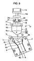
- Fig. 6 shows a second embodiment of the present invention.
- a second floating support mechanism 20 is further disposed in which the punch 18 can also freely move in the X 1 -X 2 direction.
- a rail 21 provided with a reverse T shaped slot 21a formed in the X 1 -X 2 direction is fixed to the guide member 15 in the floating support mechanism 17 in the Y 1 -Y 2 direction
- a reverse T shaped guide member 22 provided with a guide surface of the X 1 -X 2 direction is slidably fitted into the slot 21a of the rail 21, and the guide member 22 is fixed to the rod 14a of the hydraulic cylinder 14 as the raising/lowering drive means.
- the work 6 can be processed similarly as described above. Furthermore, in the second embodiment, since the floating support mechanism 20 to the X 1 -X 2 direction is added separately from the floating support mechanism 17 to the Y 1 -Y 2 direction, it is unnecessary to precisely match the movement direction of the Y 1 -Y 2 direction of the punch 18, that is, the Y 1 -Y 2 direction of the slot 16a and guide member 15 and the direction in which the axis A of the work 6 is inclined.
- the punch 18 moves in the Y 2 direction, the load to the X 1 -X 2 direction is applied to the punch 18 to prevent the punch 18 from being inserted.
- the punch 18 moves also in the X 1 -X 2 direction in the driven manner, and the expanded tube processing can satisfactorily be performed without any difficulty.
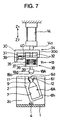
- Figs. 7 to 10 show a third embodiment according to the present invention.
- the third embodiment shows another example in which two floating support mechanisms are disposed.
- the die 2a and movable die 3a are constituted similarly as the embodiment shown in Figs. 1 and 2, the die 2a is provided with the fixed forming die 2, and the movable die 3a is provided with the movable forming die 3.
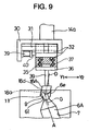
- a work is used in which a reduced diameter portion 6i is molded on one end of a rare tube portion 6h beforehand by displacing an axis G (see Fig. 9) from the axis A of the rare tube portion 6h through spinning process or swaging process. Moreover, the opening end surface 6d of the reduced diameter portion 6i of a work 6A is formed to become substantially horizontal when the work 6A is set similarly as described above.
- the enlarged diameter processing die surfaces 11, 12 in the fixed forming die 2 and movable forming die 3 are formed in sloping surfaces whose axis D slopes in the Y 1 -Y 2 direction with respect to the vertical direction as shown in Fig. 9.
- the hydraulic cylinder 14 as the raising/lowering means is pendently disposed in the immobile state, and a first support frame 30 is fixed to the lower end of the rod 14a.
- a linear rail 31 is disposed in the Y 1 -Y 2 direction, the linear rail 31 is provided with a second support frame 32 by a bearing 33 in such a manner that the frame can freely move (float) in the Y 1 -Y 2 direction, and these constitute a first floating support mechanism 34 in the Y 1 -Y 2 direction.
- a linear rail 35 is disposed in the X 1 -X 2 direction, the linear rail 35 is provided with a punch support 36 by a bearing 37 in such a manner that the support can freely move (float) in the X 1 -X 2 direction, and these constitute a second floating support mechanism 38 in the X 1 -X 2 direction.
- a rod 39 is pendently disposed, and a punch 18A is fixed to the lower end of the rod 39.
- the axis is, as shown in Fig. 9, inclined and formed in the same direction (Y 1 -Y 2 direction) as that of the axis D of the enlarged diameter processing die surfaces 11, 12 in the forming dies 2, 3, the lower part is provided with the tapered die surface 18a corresponding to the gradually changing processing die surfaces 9, 10 in the forming dies 2, 3, and the upper part is provided with the die surface 18d inclined in the Y 1 -Y 2 direction corresponding to the enlarged diameter processing die surfaces 11, 12.
- the air cylinder 39 constituting first original position return means is securely disposed to the first support frame 30 in the Y 1 -Y 2 direction, a tip end of a rod 40 is fixed to the second support frame 32, the rod 40 is advanced by air supply into the air cylinder 39 until the second support frame 32 abuts on a corresponding piece 30a of the first support frame 30, and the punch 18A returns to the original position of the Y 1 -Y 2 direction.
- the punch 18A returns to the original position of the Y 1 -Y 2 direction.
- movement of the second support frame 32 in the Y 1 -Y 2 direction can freely be performed in the constitution.
- an air cylinder 41 constituting the second original position return means is securely disposed to the second support frame 32 in the X 1 -X 2 direction, a tip end of a rod 42 is fixed to the punch support 36, the rod 42 is advanced by air supply into the air cylinder 41 until the punch support 36 abuts on a corresponding piece 32a of the second support frame 32, and the punch 18A returns to the original position of the X 1 -X 2 direction.
- the punch 18A returns to the original position of the X 1 -X 2 direction.
- by freely supplying/discharging air in the air cylinder 41 movement of the punch support 36 in the X 1 -X 2 direction can freely be performed in the constitution.
- hydraulic cylinders may be used instead of the air cylinders 39, 41.
- the work 6A molded beforehand as shown in Figs. 7 and 8 is held and fixed in an inclined state as shown in Fig. 7 by the fixed forming die 2 and movable forming die 3 similarly as the aforementioned embodiment.
- the air cylinder 14 is lowered to lower the rod 14a.
- the punch 18A is lowered in the vertical direction, and the tip end of the punch 18A is inserted into the reduced diameter portion 6i via the opening end surface 6d of the work 6A as shown in Fig. 9.
- the end 6e of the opening end surface 6d in the Y 2 direction is expanded to the outside from the inside by the tapered die surface 18a of the punch 18A. Therefore, the conventional interference fails to occur.
- the expanded tube processing can easily and securely be performed.
- the third embodiment is also provided with the floating support mechanism 38 in the X 1 -X 2 direction, similarly as the second embodiment, during processing, the load of the X 1 -X 2 direction acs on the punch 18A, then the punch 18A is driven in the load direction, and the apparatus can be simplified similarly as described above.
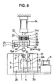
- Figs. 11 to 14 show a fourth embodiment according to the present invention.
- the floating support mechanism is disposed on a forming die side.
- a linear rail 40 is disposed in the Y 1 -Y 2 direction, a sliding member 41 is disposed to be movable in the Y 1 -Y 2 direction on the linear rail 40, and these constitute a first floating support mechanism 42 of the Y 1 -Y 2 direction.
- a support plate 43 is fixed onto the sliding member 41, a linear rail 44 is securely disposed onto the support plate 43 in the X 1 -X 2 direction, and a sliding member 45 is disposed on the linear rail 44 to be movable in the X 1 -X 2 direction.
- the linear rail 44 and sliding member 45 constitute a second floating support mechanism 46 of the X 1 -X 2 direction.
- the base 1 is fixed to the sliding member 45.
- an air cylinder 47 constituting first original position return means is securely disposed/fixed in the Y 1 -Y 2 direction, a rod 47a thereof is fixed to the support plate 43, and by air supply into the air cylinder 39 the rod 47a advances to a predetermined position until both forming dies 2, 3 return to the original position of the Y 1 -Y 2 direction.
- an air cylinder 48 constituting second original position return means is securely disposed in the X 1 -X 2 direction, a rod 48a is fixed to the base 1, and by air supply into the air cylinder 48 the rod 48a advances to the predetermined position until both forming dies 2, 3 return to the original position of the X 1 -X 2 direction.
- the air cylinder 14 as raising/lowering drive means is securely disposed vertically, and the punch 18A is fixed to the lower end of the rod 14a.
- the punch 18A is formed similarly as the punch 18A of the third embodiment shown in Figs. 7 to 10.
- air is supplied to the air cylinder 47 to set both forming dies 2, 3 in the original position of the Y 1 -Y 2 direction while air is supplied to the air cylinder 48 to set both forming dies 2, 3 in the original position of the X 1 -X 2 direction.
- the air cylinder 14 is lowered to lower the punch 18A in the vertical direction, and thus, the punch 18A is inserted via the opening of the reduced diameter portion 6i of the work 6A as shown in Fig. 13.
- both forming dies 2, 3 are driven in the Y 2 direction. Therefore, both forming dies 2, 3 move in the Y 2 direction, the punch 18A is inserted and the reduced diameter portion 6i of the work 6A is molded into the gradually changing portion 6j and expanded tube portion 6k as shown in Fig. 14.
- the second floating support mechanism 42 moves both forming dies 2, 3 in the Y 1 direction and the punch 18A is removed from the die along the path reverse to the insertion path.
- the fourth embodiment is also provided with the floating support mechanism 46 to the X 1 -X 2 direction, during the processing by the punch 18A the load of the X 1 -X 2 direction acts on both forming dies 2, 3, then both forming dies 2, 3 are driven in the load direction, and the apparatus can be simplified similarly as described above.
- Figs. 15 and 16 show a fifth embodiment.
- the original position return means 39, 41 in the third embodiment shown in Figs. 7 to 10 are formed by urging means for constant urging to the original position direction, and the drawings show an example in which a spring is used.
- a spring 50 for constantly urging the second support frame 32 in the Y 2 direction is interposed between the first support frame 30 and the second support frame 32 in Figs. 7 and 8, and a spring 51 for constantly urging the punch support 36 in the X 2 direction is interposed between the second support frame 32 and the punch support 36.
- either one of the work side and the punch side is moved in a horizontal direction (X 1 -X 2 , Y 1 -Y 2 direction), but both the work side and the punch side may be moved in the horizontal direction (X 1 -X 2 , Y 1 -Y 2 direction).
- the work is disposed in such a manner that the opening end surface is turned upward, but when the work is disposed to turn the opening end surface sideways and the punch is inserted substantially horizontally from the sideways opening end surface, the X 1 -X 2 and Y 1 -Y 2 directions are set in a vertical plane.
- the return means 47, 48 shown in Figs. 11 to 14 may be constituted by urging means formed of the spring shown in Figs. 15 and 16.
- transverse sections of the expanded tube portion and gradually changing portion of the work may be provided with irregular shapes such as elliptical, substantially triangle and substantially square shapes as shown in Figs. 17A to 17F.
- the shapes of the punch and work forming die are formed in the shapes adapted to the aforementioned irregular shapes, and the work forming die is constituted in such a manner that the processed work can be extracted.
- an expanded tube processing method of a cylindrical tube in which a punch is disposed on the side of an opening end of a work formed of the metal cylindrical tube and the punch is inserted from the opening end of the work to enlarge the diameter of an end of the work, by inserting the punch from the opening end of the work at a predetermined angle with respect to a tube axis of the work, and moving the punch and/or the work during insertion of the punch in a direction substantially crossing at right angles to the punch insertion path to perform an expanded tube processing, an expanded tube portion provided with an axis inclined with respect to the axis of the work can be formed.
- the work opening end is pressed to the outside from the inside with the punch to eliminate the aforementioned conventional interference of the punch with the work opening end and the work can be subjected to the tube expansion.
- the work opening end surface on the side of insertion of the punch to be substantially at right angles to the insertion path of the punch, the work opening end surface can be formed in the direction substantially crossing at right angles to the punch insertion path, the punch can easily be inserted, and the tube expansion can easily be performed.
- the work is inclined and held with respect to the vertical direction, the insertion path of the punch is vertical, and movement of the punch and/or the work in the direction substantially crossing at right angles to the work insertion path is set to the movement of the horizontal direction.
- the punch insertion path is vertical
- general-purpose facilities press machine, tube expander
- the movement of the direction substantially crossing at right angles to the punch insertion path is the horizontal movement, as compared with the conventional movement along the inclined surface shown in Fig. 22, the punch smoothly moves, the movement in the specific direction by inclination fails to occur, and high-precision tube expansion is possible.
- the movement in the direction substantially crossing at right angles to the punch insertion path in the punch and/or the work is performed in at least two directions, by moving the punch and/or the work in at least two directions, it is unnecessary to match the movement direction of the punch and/or the work with the inclination direction of the expanded tube portion, and arrangement of the facilities is simplified.
- the apparatus comprises: a forming die for holding the work in an inclined state with respect to a punch insertion path; driving means for moving the punch in a direction of the insertion path; and a support mechanism for supporting the punch and/or the work in a direction substantially crossing at right angles to the insertion path of the work in such a manner that floating is possible, or further a work opening end surface on the side of insertion of the punch is formed to be substantially at right angles to the insertion path of the punch, so that the expanded tube processing method can be achieved.
- the punch and/or the work is constituted to move in the direction substantially crossing at right angles to the work insertion path, and is supported in a floating manner, the movement in the direction crossing at right angles to the work insertion path is naturally performed in a driven manner by the reaction acting on the punch and/or the work. Therefore, no moving drive means is necessary, and the tube expansion can satisfactorily be performed with a simple apparatus.
- the forming die of the work is formed to incline and hold the work with respect to a vertical direction
- the insertion path of the punch is set in a vertical direction
- a floating direction of the punch and/or the work is set to a horizontal direction, so that the expanded tube processing method can be achieved.
- the expanded tube processing method by setting the floating direction of the punch and/or the work to at least two directions, the expanded tube processing method can be achieved.
- the expanded tube processing apparatus by providing return means for returning the punch and/or the work to an original position side on which the tube expansion starts in the floating direction, after completion of the expanded tube processing the punch and/or the work is automatically returned to the original position in which the tube expansion starts, an operator's trouble for manual returning can be saved, and operation efficiency can be achieved.
- the return means comprises urging means for constant urging to the original position side
- the urging force constantly acts on the punch and/or the work in the direction opposite to the horizontal movement direction, the deflection or the like of the punch or the work can be prevented and the high precision of the tube expansion can be achieved.
- the apparatus comprises: a forming die for securely holding the work in such a manner that an end of the work is inclined with respect to a punch insertion path; driving means for moving the work in a direction of the insertion path; and a support mechanism for supporting the punch in a direction substantially crossing at right angles to the insertion path of the work in such a manner that floating is possible, the lightweight punch is moved rather than the work forming die, and therefore the movement structure can easily be constituted.
Landscapes
- Engineering & Computer Science (AREA)
- Mechanical Engineering (AREA)
- Shaping Metal By Deep-Drawing, Or The Like (AREA)
- Punching Or Piercing (AREA)
- Shaping By String And By Release Of Stress In Plastics And The Like (AREA)
- Processing Of Terminals (AREA)
Claims (10)
- Verfahren zum Aufweiten eines Rohrmaterials eines zylindrischen Rohres, bei dem eins Stempel (18) auf der Seite eines offenen Endes eines Werkstücks (6) aus dem zylindrischen Metallrohr angeordnet ist und von dem offenen Ende des Werkstücks (6) zum Vergrößern des Durchmessers eines Endes des Werkstücks (6) eingesetzt wird, umfassen die Schritte: Einsetzen des Stempels 18 vom offenen Ende des Werkstücks,
dadurch gekennzeichnet, dass
das Einsetzen bei einem bestimmten Winkel in bezug auf eine Rohrachse des Werkstücks (6) durchgeführt wird, wobei während des Einsetzens des Stempels (18), der Stempel (18) und/oder das Werkstück (6) in einer Richtung (X1-X2; Y1-Y2), die einen Einsetzweg (Z1-Z2) des Stempels (18) im Wesentlichen rechtwinklig kreuzt, bewegt werden, um das Aufweiten des Rohrmaterials durchzuführen. - Verfahren zum Aufweiten eines Rohrmaterials nach Anspruch 1, wobei eine Endfläche (6d) der Werkstücköffnung an der Einsetzseite des Stempels (18) im Wesentlichen rechtwinklig zum Einsetzweg (Z1-Z2) des Stempels (18) ausgebildet ist.
- Verfahren zum Aufweiten eines Rohrmaterials nach Anspruch 1, wobei das Werkstück (6) geneigt zu einer vertikalen Richtung gehalten wird, der Einsetzweg (Z1-Z2) des Stempels (18) vertikal verläuft, und eine Bewegung des Stempels (18) und/oder des Werkstücks in der den Einsetzweg (Z1-Z2) des Stempels (18) im Wesentlichen rechtwinklig kreuzenden Richtung eine Bewegung in horizontaler Richtung ist.
- Verfahren zum Aufweiten eines Rohrmaterials nach einem der Ansprüche 1 bis 3, wobei die den Einsetzweg (Z1-Z2) des Stempels (18) und/oder des Werkstücks im Wesentlichen rechtwinklig kreuzende Bewegung der Richtung (X1-X2, Y1-Y2) in mindestens zwei Richtungen erfolgt.
- Vorrichtung zum Aufweiten eines Rohrmaterials eines zylindrischen Rohres, bei dem ein Stempel (18) auf der Seite eines offenen Endes eines Werkstücks (6) aus dem zylindrischen Metallrohr angeordnet ist und von dem offenen Ende des Werkstücks (6) zum Vergrößern des Durchmessers eines Endes des Werkstücks eingesetzt wird, umfassend
einen Formkörper (2, 3) zum Halten des Werkstücks (6),
eine Antriebseinrichtung zum Bewegen des Stempels (18) und/oder des Werkstücks (6) in eine Richtung eines Einsetzweges (Z1-Z2)
dadurch gekennzeichnet, dass
der Formkörper (2, 3) das Werkstück (6) in einer geneigten Lage in bezug auf den Einsetzweg (Z1-Z2) des Stempels (18) hält, und dass
ein Lager (17, 20, 34, 38, 42, 46) den Stempel (18) und/oder das Werkstück (6) in einer den Einsetzweg (Z1-Z2) des Stempels (18) im Wesentlichen rechtwinklig kreuzenden Richtung (X1-X2; Y1-Y2) lagert, sodass ein schwimmendes Lagern ermöglicht wird. - Vorrichtung zum Aufweiten eines Rohrmaterials nach Anspruch 5, wobei eine Endfläche (6d) der Werkstücköffnung an der Einsetzseite des Stempels (18) im Wesentlichen rechtwinklig zum Einsetzweg (Z1-Z2) des Stempels (18) ausgebildet ist.
- Vorrichtung zum Aufweiten eines Rohrmaterials nach Anspruch 5 oder 6, wobei der Formkörper (2, 3) des Werkstücks (6) ausgebildet ist, um das Werkstück (6) geneigt in bezug auf eine vertikale Richtung zu halten, der Einsetzweg (Z1-Z2) des Stempels (18) vertikal verläuft und eine Schwimmrichtung des Stempels (18) und/oder des Werkstücks (6) eine horizontale Richtung ist.
- Vorrichtung zum Aufweiten eines Rohrmaterials nach einem der Ansprüche 5 bis 7, wobei die Schwimmrichtung (X1-X2; Y1-Y2) des Stempels (18) und/oder des Werkstücks (6) mindestens zwei Richtungen umfaßt.
- Vorrichtung zum Aufweiten eines Rohrmaterials nach einem der Ansprüche 5 bis 8, weiter umfassend eine Rückführeinrichtung (39, 41, 47, 48) zur Rückführung des Stempels (18) und/oder des Werkstücks (6) zu einer Ausgangspositionsseite, an der die Aufweitung des Rohres in der Schwimmeinrichtung beginnt.
- Vorrichtung zum Aufweiten eines Rohrmaterials nach Anspruch 9, wobei die Rückführeinrichtungen Spanneinrichtungen (39, 41, 47, 48) zum konstanten Spannen des Stempels und/oder des Werkstücks zur Ausgangspositionsseite umfassen.
Applications Claiming Priority (3)
| Application Number | Priority Date | Filing Date | Title |
|---|---|---|---|
| JP17346299 | 1999-06-21 | ||
| JP11173462A JP3027581B1 (ja) | 1999-06-21 | 1999-06-21 | 管材の拡管加工方法及び管材の拡管加工装置 |
| PCT/JP2000/004038 WO2000078479A1 (en) | 1999-06-21 | 2000-06-21 | Method and device for expanding tube material |
Publications (3)
| Publication Number | Publication Date |
|---|---|
| EP1121998A1 EP1121998A1 (de) | 2001-08-08 |
| EP1121998A4 EP1121998A4 (de) | 2003-04-23 |
| EP1121998B1 true EP1121998B1 (de) | 2004-12-15 |
Family
ID=15960933
Family Applications (1)
| Application Number | Title | Priority Date | Filing Date |
|---|---|---|---|
| EP00940772A Expired - Lifetime EP1121998B1 (de) | 1999-06-21 | 2000-06-21 | Verfahren und vorrichtung zum ausweiten eines rohrmaterials |
Country Status (6)
| Country | Link |
|---|---|
| US (1) | US6530256B1 (de) |
| EP (1) | EP1121998B1 (de) |
| JP (1) | JP3027581B1 (de) |
| AT (1) | ATE284765T1 (de) |
| DE (1) | DE60016709T2 (de) |
| WO (1) | WO2000078479A1 (de) |
Families Citing this family (16)
| Publication number | Priority date | Publication date | Assignee | Title |
|---|---|---|---|---|
| JP3905278B2 (ja) * | 1999-02-23 | 2007-04-18 | カルソニックカンセイ株式会社 | 熱交換器チューブ用口拡爪および熱交換器におけるヘッダー部材へのチューブの取付構造 |
| US6390124B1 (en) * | 1999-08-06 | 2002-05-21 | Futaba Industrial Co. Ltd. | Fuel inlet and manufacturing method thereof |
| US20040021289A1 (en) * | 2002-08-05 | 2004-02-05 | Ku Wu | Multi-stage tube forging method for disproportionally enlarging an end section of a tube of a bicycle frame part |
| DE10320106A1 (de) * | 2003-05-05 | 2004-12-09 | Carl Froh Gmbh | Gasführungsrohr aus Metall für Luftsäcke von Kraftwagen und Verfahren zu dessen Herstellung |
| JP4346951B2 (ja) * | 2003-05-08 | 2009-10-21 | 株式会社ベステックスキョーエイ | フューエルインレットの製造方法 |
| US7073364B2 (en) * | 2004-05-27 | 2006-07-11 | Krish Sr Joseph J | Die assembly having floating die section |
| JP4941054B2 (ja) * | 2007-03-30 | 2012-05-30 | 住友金属工業株式会社 | 継目無ベンド管の製造方法並びに溶接継手及びその製造方法 |
| DK2155311T3 (da) * | 2007-06-20 | 2013-02-04 | Unomedical As | Fremgangsmåde og apparat til fremstilling af et kateter |
| US9250050B2 (en) | 2011-10-21 | 2016-02-02 | Setpoint Systems, Inc. | Apparatus, system, and method for ammunition cartridge case annealing |
| US9157709B2 (en) | 2011-12-08 | 2015-10-13 | Setpoint Systems, Inc. | Apparatus, system, and method for manufacturing ammunition cartridge cases |
| TWI526259B (zh) * | 2014-11-19 | 2016-03-21 | Tai Hung Lee | A tube management device with a view hole |
| US10702902B2 (en) | 2014-12-26 | 2020-07-07 | Nippon Steel Corporation | Method of manufacturing flaring-processed metal pipe |
| JP6665643B2 (ja) * | 2016-04-06 | 2020-03-13 | 日本製鉄株式会社 | 拡径管部品の製造方法および製造装置 |
| DE102017117400A1 (de) * | 2017-08-01 | 2019-02-07 | Liebherr-Aerospace Lindenberg Gmbh | Vorrichtung zur Installation und/oder Umformung von Buchsen |
| GB2592452B (en) * | 2020-07-28 | 2023-05-24 | Frugalpac Ltd | Apparatus for manufacturing a container |
| CN117900322B (zh) * | 2023-12-31 | 2025-11-14 | 广西玉林坤达机械制造有限责任公司 | 一种平板式芯片涨管工装 |
Family Cites Families (9)
| Publication number | Priority date | Publication date | Assignee | Title |
|---|---|---|---|---|
| US1230177A (en) * | 1915-09-28 | 1917-06-19 | Greenfield Paper Bottle Company | Manufacture of paper bottles. |
| US2060690A (en) * | 1934-07-09 | 1936-11-10 | Allied Prod Corp | Drawing die |
| US2245642A (en) * | 1938-08-26 | 1941-06-17 | Edgewater Steel | Forging die |
| ES450061A1 (es) * | 1975-10-14 | 1977-11-16 | Gen Tire & Rubber Co | Un procedimiento para fabricar un elemento metalico anular con tolerancias precisas. |
| JPS5452664A (en) * | 1977-10-04 | 1979-04-25 | Sanyo Electric Co Ltd | Forming method for pipe at pipe joint portion |
| JPS58185336A (ja) | 1982-04-26 | 1983-10-29 | Nissan Motor Co Ltd | 車両用音声認識装置 |
| JPS58185336U (ja) * | 1982-06-04 | 1983-12-09 | 株式会社日立製作所 | 拡管工具 |
| JPH0732942B2 (ja) * | 1991-05-22 | 1995-04-12 | 株式会社三五 | 屈曲金属パイプ及びその成形方法 |
| JP4086394B2 (ja) | 1998-12-24 | 2008-05-14 | 株式会社三五 | 管素材の端部成形方法及び装置 |
-
1999
- 1999-06-21 JP JP11173462A patent/JP3027581B1/ja not_active Expired - Fee Related
-
2000
- 2000-06-21 US US09/763,208 patent/US6530256B1/en not_active Expired - Lifetime
- 2000-06-21 AT AT00940772T patent/ATE284765T1/de not_active IP Right Cessation
- 2000-06-21 EP EP00940772A patent/EP1121998B1/de not_active Expired - Lifetime
- 2000-06-21 WO PCT/JP2000/004038 patent/WO2000078479A1/ja not_active Ceased
- 2000-06-21 DE DE60016709T patent/DE60016709T2/de not_active Expired - Lifetime
Also Published As
| Publication number | Publication date |
|---|---|
| WO2000078479A1 (en) | 2000-12-28 |
| DE60016709D1 (de) | 2005-01-20 |
| JP3027581B1 (ja) | 2000-04-04 |
| ATE284765T1 (de) | 2005-01-15 |
| US6530256B1 (en) | 2003-03-11 |
| DE60016709T2 (de) | 2005-12-22 |
| EP1121998A1 (de) | 2001-08-08 |
| EP1121998A4 (de) | 2003-04-23 |
| JP2001001083A (ja) | 2001-01-09 |
Similar Documents
| Publication | Publication Date | Title |
|---|---|---|
| EP1121998B1 (de) | Verfahren und vorrichtung zum ausweiten eines rohrmaterials | |
| EP1535674B1 (de) | Formwerkzeug für eine Presse zum Biegen eines negativen Winkels | |
| EP0865846A1 (de) | Stanzmaschine und stanzverfahren | |
| JP2889951B2 (ja) | タレットパンチプレスのダイ昇降機構 | |
| US6220137B1 (en) | Press apparatus | |
| CN1332063A (zh) | 自动定心修边冲头 | |
| JP3069083B2 (ja) | プレス装置 | |
| JPH09308919A (ja) | 管材のバーリング加工装置 | |
| US4434639A (en) | Arrangement for producing drawn formations on workpieces, particularly in a cutting and pressing machine | |
| JPH05111724A (ja) | パイプ材の孔あけ時における雌型の支持装置及び支持 方法 | |
| CN217941560U (zh) | 管件翻边机构 | |
| JP2001170723A (ja) | 縮管方法および縮管装置 | |
| JP3170100B2 (ja) | 複合加工機 | |
| JP2723791B2 (ja) | ベンド成形方法と成形装置 | |
| EP0557551A1 (de) | Gesenk mit Dreier-Führungsstruktur | |
| JPH0788734A (ja) | プラネタリーギヤ組立装置 | |
| JP2539321Y2 (ja) | 多段式圧造成形機 | |
| JPH06297054A (ja) | パンチングプレス | |
| JPH07185728A (ja) | 大口径リングの鍛造装置 | |
| JP2001246434A (ja) | 型交換装置 | |
| KR100401739B1 (ko) | 용접용 지그 구조 | |
| JP2005523824A (ja) | 連接棒プリフォームの破砕装置及び方法 | |
| JPH05192834A (ja) | 複合加工機 | |
| CN121244772A (zh) | 四通阀管的s管冲孔翻边机构及设有该机构的冲孔翻边机 | |
| CN114210833A (zh) | 一种汽车后桥控制杆支架成形模具及其加工工艺 |
Legal Events
| Date | Code | Title | Description |
|---|---|---|---|
| PUAI | Public reference made under article 153(3) epc to a published international application that has entered the european phase |
Free format text: ORIGINAL CODE: 0009012 |
|
| 17P | Request for examination filed |
Effective date: 20010212 |
|
| AK | Designated contracting states |
Kind code of ref document: A1 Designated state(s): AT BE CH CY DE DK ES FI FR GB GR IE IT LI LU MC NL PT SE |
|
| AX | Request for extension of the european patent |
Free format text: AL;LT;LV;MK;RO;SI |
|
| A4 | Supplementary search report drawn up and despatched |
Effective date: 20030306 |
|
| 17Q | First examination report despatched |
Effective date: 20031107 |
|
| GRAP | Despatch of communication of intention to grant a patent |
Free format text: ORIGINAL CODE: EPIDOSNIGR1 |
|
| GRAS | Grant fee paid |
Free format text: ORIGINAL CODE: EPIDOSNIGR3 |
|
| GRAA | (expected) grant |
Free format text: ORIGINAL CODE: 0009210 |
|
| AK | Designated contracting states |
Kind code of ref document: B1 Designated state(s): AT BE CH CY DE DK ES FI FR GB GR IE IT LI LU MC NL PT SE |
|
| PG25 | Lapsed in a contracting state [announced via postgrant information from national office to epo] |
Ref country code: BE Free format text: LAPSE BECAUSE OF FAILURE TO SUBMIT A TRANSLATION OF THE DESCRIPTION OR TO PAY THE FEE WITHIN THE PRESCRIBED TIME-LIMIT Effective date: 20041215 Ref country code: NL Free format text: LAPSE BECAUSE OF FAILURE TO SUBMIT A TRANSLATION OF THE DESCRIPTION OR TO PAY THE FEE WITHIN THE PRESCRIBED TIME-LIMIT Effective date: 20041215 Ref country code: LI Free format text: LAPSE BECAUSE OF FAILURE TO SUBMIT A TRANSLATION OF THE DESCRIPTION OR TO PAY THE FEE WITHIN THE PRESCRIBED TIME-LIMIT Effective date: 20041215 Ref country code: FI Free format text: LAPSE BECAUSE OF FAILURE TO SUBMIT A TRANSLATION OF THE DESCRIPTION OR TO PAY THE FEE WITHIN THE PRESCRIBED TIME-LIMIT Effective date: 20041215 Ref country code: AT Free format text: LAPSE BECAUSE OF FAILURE TO SUBMIT A TRANSLATION OF THE DESCRIPTION OR TO PAY THE FEE WITHIN THE PRESCRIBED TIME-LIMIT Effective date: 20041215 Ref country code: CH Free format text: LAPSE BECAUSE OF FAILURE TO SUBMIT A TRANSLATION OF THE DESCRIPTION OR TO PAY THE FEE WITHIN THE PRESCRIBED TIME-LIMIT Effective date: 20041215 |
|
| REG | Reference to a national code |
Ref country code: CH Ref legal event code: EP Ref country code: GB Ref legal event code: FG4D |
|
| RIN1 | Information on inventor provided before grant (corrected) |
Inventor name: MORIKAWA, AKINOBUYAWATAYAMA KOJO, SANGO CO., LTD. Inventor name: IRIE, TOHRU,YAWATAYAMA KOJO, SANGO CO., LTD. Inventor name: HAYAKAWA, HISASHI,YAWATAYAMA KOJO, SANGO CO.,LTD. |
|
| REG | Reference to a national code |
Ref country code: IE Ref legal event code: FG4D |
|
| REF | Corresponds to: |
Ref document number: 60016709 Country of ref document: DE Date of ref document: 20050120 Kind code of ref document: P |
|
| PG25 | Lapsed in a contracting state [announced via postgrant information from national office to epo] |
Ref country code: GR Free format text: LAPSE BECAUSE OF FAILURE TO SUBMIT A TRANSLATION OF THE DESCRIPTION OR TO PAY THE FEE WITHIN THE PRESCRIBED TIME-LIMIT Effective date: 20050315 Ref country code: DK Free format text: LAPSE BECAUSE OF FAILURE TO SUBMIT A TRANSLATION OF THE DESCRIPTION OR TO PAY THE FEE WITHIN THE PRESCRIBED TIME-LIMIT Effective date: 20050315 Ref country code: SE Free format text: LAPSE BECAUSE OF FAILURE TO SUBMIT A TRANSLATION OF THE DESCRIPTION OR TO PAY THE FEE WITHIN THE PRESCRIBED TIME-LIMIT Effective date: 20050315 |
|
| PG25 | Lapsed in a contracting state [announced via postgrant information from national office to epo] |
Ref country code: ES Free format text: LAPSE BECAUSE OF FAILURE TO SUBMIT A TRANSLATION OF THE DESCRIPTION OR TO PAY THE FEE WITHIN THE PRESCRIBED TIME-LIMIT Effective date: 20050326 |
|
| NLV1 | Nl: lapsed or annulled due to failure to fulfill the requirements of art. 29p and 29m of the patents act | ||
| PG25 | Lapsed in a contracting state [announced via postgrant information from national office to epo] |
Ref country code: CY Free format text: LAPSE BECAUSE OF FAILURE TO SUBMIT A TRANSLATION OF THE DESCRIPTION OR TO PAY THE FEE WITHIN THE PRESCRIBED TIME-LIMIT Effective date: 20050621 Ref country code: IE Free format text: LAPSE BECAUSE OF NON-PAYMENT OF DUE FEES Effective date: 20050621 Ref country code: LU Free format text: LAPSE BECAUSE OF NON-PAYMENT OF DUE FEES Effective date: 20050621 |
|
| PG25 | Lapsed in a contracting state [announced via postgrant information from national office to epo] |
Ref country code: MC Free format text: LAPSE BECAUSE OF NON-PAYMENT OF DUE FEES Effective date: 20050630 |
|
| REG | Reference to a national code |
Ref country code: CH Ref legal event code: PL |
|
| PLBE | No opposition filed within time limit |
Free format text: ORIGINAL CODE: 0009261 |
|
| STAA | Information on the status of an ep patent application or granted ep patent |
Free format text: STATUS: NO OPPOSITION FILED WITHIN TIME LIMIT |
|
| ET | Fr: translation filed | ||
| 26N | No opposition filed |
Effective date: 20050916 |
|
| REG | Reference to a national code |
Ref country code: IE Ref legal event code: MM4A |
|
| PG25 | Lapsed in a contracting state [announced via postgrant information from national office to epo] |
Ref country code: PT Free format text: LAPSE BECAUSE OF NON-PAYMENT OF DUE FEES Effective date: 20050515 |
|
| PGFP | Annual fee paid to national office [announced via postgrant information from national office to epo] |
Ref country code: GB Payment date: 20140618 Year of fee payment: 15 |
|
| PGFP | Annual fee paid to national office [announced via postgrant information from national office to epo] |
Ref country code: IT Payment date: 20140618 Year of fee payment: 15 Ref country code: DE Payment date: 20140630 Year of fee payment: 15 |
|
| PGFP | Annual fee paid to national office [announced via postgrant information from national office to epo] |
Ref country code: FR Payment date: 20140630 Year of fee payment: 15 |
|
| REG | Reference to a national code |
Ref country code: DE Ref legal event code: R119 Ref document number: 60016709 Country of ref document: DE |
|
| PG25 | Lapsed in a contracting state [announced via postgrant information from national office to epo] |
Ref country code: IT Free format text: LAPSE BECAUSE OF NON-PAYMENT OF DUE FEES Effective date: 20150621 |
|
| GBPC | Gb: european patent ceased through non-payment of renewal fee |
Effective date: 20150621 |
|
| REG | Reference to a national code |
Ref country code: FR Ref legal event code: ST Effective date: 20160229 |
|
| PG25 | Lapsed in a contracting state [announced via postgrant information from national office to epo] |
Ref country code: GB Free format text: LAPSE BECAUSE OF NON-PAYMENT OF DUE FEES Effective date: 20150621 Ref country code: DE Free format text: LAPSE BECAUSE OF NON-PAYMENT OF DUE FEES Effective date: 20160101 |
|
| PG25 | Lapsed in a contracting state [announced via postgrant information from national office to epo] |
Ref country code: FR Free format text: LAPSE BECAUSE OF NON-PAYMENT OF DUE FEES Effective date: 20150630 |