EP1105332B1 - Gerät zum übertragen eines in form eines filmes auf ein trägerband aufgebrachten stoffes auf ein substrat - Google Patents
Gerät zum übertragen eines in form eines filmes auf ein trägerband aufgebrachten stoffes auf ein substrat Download PDFInfo
- Publication number
- EP1105332B1 EP1105332B1 EP99944355A EP99944355A EP1105332B1 EP 1105332 B1 EP1105332 B1 EP 1105332B1 EP 99944355 A EP99944355 A EP 99944355A EP 99944355 A EP99944355 A EP 99944355A EP 1105332 B1 EP1105332 B1 EP 1105332B1
- Authority
- EP
- European Patent Office
- Prior art keywords
- carrier strip
- film
- foot
- extension arm
- applicator foot
- Prior art date
- Legal status (The legal status is an assumption and is not a legal conclusion. Google has not performed a legal analysis and makes no representation as to the accuracy of the status listed.)
- Expired - Lifetime
Links
Images


Classifications
-
- B—PERFORMING OPERATIONS; TRANSPORTING
- B65—CONVEYING; PACKING; STORING; HANDLING THIN OR FILAMENTARY MATERIAL
- B65H—HANDLING THIN OR FILAMENTARY MATERIAL, e.g. SHEETS, WEBS, CABLES
- B65H37/00—Article or web delivery apparatus incorporating devices for performing specified auxiliary operations
- B65H37/002—Web delivery apparatus, the web serving as support for articles, material or another web
- B65H37/005—Hand-held apparatus
- B65H37/007—Applicators for applying coatings, e.g. correction, colour or adhesive coatings
-
- Y—GENERAL TAGGING OF NEW TECHNOLOGICAL DEVELOPMENTS; GENERAL TAGGING OF CROSS-SECTIONAL TECHNOLOGIES SPANNING OVER SEVERAL SECTIONS OF THE IPC; TECHNICAL SUBJECTS COVERED BY FORMER USPC CROSS-REFERENCE ART COLLECTIONS [XRACs] AND DIGESTS
- Y10—TECHNICAL SUBJECTS COVERED BY FORMER USPC
- Y10T—TECHNICAL SUBJECTS COVERED BY FORMER US CLASSIFICATION
- Y10T156/00—Adhesive bonding and miscellaneous chemical manufacture
- Y10T156/12—Surface bonding means and/or assembly means with cutting, punching, piercing, severing or tearing
- Y10T156/1348—Work traversing type
-
- Y—GENERAL TAGGING OF NEW TECHNOLOGICAL DEVELOPMENTS; GENERAL TAGGING OF CROSS-SECTIONAL TECHNOLOGIES SPANNING OVER SEVERAL SECTIONS OF THE IPC; TECHNICAL SUBJECTS COVERED BY FORMER USPC CROSS-REFERENCE ART COLLECTIONS [XRACs] AND DIGESTS
- Y10—TECHNICAL SUBJECTS COVERED BY FORMER USPC
- Y10T—TECHNICAL SUBJECTS COVERED BY FORMER US CLASSIFICATION
- Y10T156/00—Adhesive bonding and miscellaneous chemical manufacture
- Y10T156/17—Surface bonding means and/or assemblymeans with work feeding or handling means
- Y10T156/1788—Work traversing type and/or means applying work to wall or static structure
- Y10T156/1795—Implement carried web supply
-
- Y—GENERAL TAGGING OF NEW TECHNOLOGICAL DEVELOPMENTS; GENERAL TAGGING OF CROSS-SECTIONAL TECHNOLOGIES SPANNING OVER SEVERAL SECTIONS OF THE IPC; TECHNICAL SUBJECTS COVERED BY FORMER USPC CROSS-REFERENCE ART COLLECTIONS [XRACs] AND DIGESTS
- Y10—TECHNICAL SUBJECTS COVERED BY FORMER USPC
- Y10T—TECHNICAL SUBJECTS COVERED BY FORMER US CLASSIFICATION
- Y10T156/00—Adhesive bonding and miscellaneous chemical manufacture
- Y10T156/18—Surface bonding means and/or assembly means with handle or handgrip
-
- Y—GENERAL TAGGING OF NEW TECHNOLOGICAL DEVELOPMENTS; GENERAL TAGGING OF CROSS-SECTIONAL TECHNOLOGIES SPANNING OVER SEVERAL SECTIONS OF THE IPC; TECHNICAL SUBJECTS COVERED BY FORMER USPC CROSS-REFERENCE ART COLLECTIONS [XRACs] AND DIGESTS
- Y10—TECHNICAL SUBJECTS COVERED BY FORMER USPC
- Y10T—TECHNICAL SUBJECTS COVERED BY FORMER US CLASSIFICATION
- Y10T29/00—Metal working
- Y10T29/49—Method of mechanical manufacture
- Y10T29/49826—Assembling or joining
- Y10T29/49863—Assembling or joining with prestressing of part
- Y10T29/4987—Elastic joining of parts
-
- Y—GENERAL TAGGING OF NEW TECHNOLOGICAL DEVELOPMENTS; GENERAL TAGGING OF CROSS-SECTIONAL TECHNOLOGIES SPANNING OVER SEVERAL SECTIONS OF THE IPC; TECHNICAL SUBJECTS COVERED BY FORMER USPC CROSS-REFERENCE ART COLLECTIONS [XRACs] AND DIGESTS
- Y10—TECHNICAL SUBJECTS COVERED BY FORMER USPC
- Y10T—TECHNICAL SUBJECTS COVERED BY FORMER US CLASSIFICATION
- Y10T29/00—Metal working
- Y10T29/49—Method of mechanical manufacture
- Y10T29/49826—Assembling or joining
- Y10T29/49863—Assembling or joining with prestressing of part
- Y10T29/49876—Assembling or joining with prestressing of part by snap fit
-
- Y—GENERAL TAGGING OF NEW TECHNOLOGICAL DEVELOPMENTS; GENERAL TAGGING OF CROSS-SECTIONAL TECHNOLOGIES SPANNING OVER SEVERAL SECTIONS OF THE IPC; TECHNICAL SUBJECTS COVERED BY FORMER USPC CROSS-REFERENCE ART COLLECTIONS [XRACs] AND DIGESTS
- Y10—TECHNICAL SUBJECTS COVERED BY FORMER USPC
- Y10T—TECHNICAL SUBJECTS COVERED BY FORMER US CLASSIFICATION
- Y10T29/00—Metal working
- Y10T29/53—Means to assemble or disassemble
- Y10T29/53313—Means to interrelatedly feed plural work parts from plural sources without manual intervention
- Y10T29/53383—Means to interrelatedly feed plural work parts from plural sources without manual intervention and means to fasten work parts together
- Y10T29/53391—Means to interrelatedly feed plural work parts from plural sources without manual intervention and means to fasten work parts together by elastic joining
-
- Y—GENERAL TAGGING OF NEW TECHNOLOGICAL DEVELOPMENTS; GENERAL TAGGING OF CROSS-SECTIONAL TECHNOLOGIES SPANNING OVER SEVERAL SECTIONS OF THE IPC; TECHNICAL SUBJECTS COVERED BY FORMER USPC CROSS-REFERENCE ART COLLECTIONS [XRACs] AND DIGESTS
- Y10—TECHNICAL SUBJECTS COVERED BY FORMER USPC
- Y10T—TECHNICAL SUBJECTS COVERED BY FORMER US CLASSIFICATION
- Y10T29/00—Metal working
- Y10T29/53—Means to assemble or disassemble
- Y10T29/534—Multiple station assembly or disassembly apparatus
- Y10T29/53417—Means to fasten work parts together
- Y10T29/53426—Means to fasten work parts together by elastic joining
-
- Y—GENERAL TAGGING OF NEW TECHNOLOGICAL DEVELOPMENTS; GENERAL TAGGING OF CROSS-SECTIONAL TECHNOLOGIES SPANNING OVER SEVERAL SECTIONS OF THE IPC; TECHNICAL SUBJECTS COVERED BY FORMER USPC CROSS-REFERENCE ART COLLECTIONS [XRACs] AND DIGESTS
- Y10—TECHNICAL SUBJECTS COVERED BY FORMER USPC
- Y10T—TECHNICAL SUBJECTS COVERED BY FORMER US CLASSIFICATION
- Y10T83/00—Cutting
- Y10T83/02—Other than completely through work thickness
- Y10T83/0267—Splitting
Definitions
- the invention relates to a device for transmitting a Form of a film on a carrier tape on a substrate, such as a writing or drawing sheet, with a housing in which a supply spool for the film-coated Carrier tape and an empty spool to hold the stripped carrier tape are arranged, the film-coated carrier tape passed over an application foot which is at least in the loop wrapped by the carrier tape Area with a clip-like sliding element from one friction-reducing material is provided, which on Order foot is attached.
- Handheld devices of this type for transferring a film are known. They are to ensure smooth operation and good portability to strive for the film on the substrate, different Designs for the design of the order foot known.
- the job foot can be used with a Applicator roll be equipped, which is preferably a rubber elastic Has tread.
- a functional job role is not arbitrary can be kept small because of a good fit the substrate has a minimum thickness for the elastic race requires and the rotational mobility a sufficient difference between stub axle and outside diameter, such an order role has disadvantages.
- the order foot is an order bar on that advantages over a job role has, because a sharper bending of the carrier tape in the Transfer phase is possible, which causes the demolition after completion Transfer less to the formation of a flutter edge inclines.
- Disadvantageous compared to a solution with an order role is against that in the order bar the carrier tape under frictional engagement over this, depending on the quality of the carrier tape lead to unwanted stiffness can.
- plastics are known that have good sliding behavior have, such as polytetrafluoroethylene (PTFE), which is however many times higher in price lies than that usually for the components of a generic Standard materials used in the device. For cost reasons therefore the use of an order foot is excluded made of polytetrafluoroethylene.
- PTFE polytetrafluoroethylene
- polytetrafluoroethylene is not a real thermoplastic, it must also exclude the sliding active area of the Application foot in the multi-component or back injection process with this high quality material.
- a conceivable solution like masking the job bar with a self-adhesive fluoroplastic-coated film already examined, but from a manufacturing point of view View unsuitable for a mass article.
- a generic device is known from US-A-5,430,904. With this device, the application foot is wrapped in the carrier tape Area with a sliding element made of a friction-reducing rubber-like material provided on the application foot is attached. This sliding element is intended to a perfect transfer of the film to the substrate to reach. However, it has been found that the smooth operation of the device and the transmission of the Film on the substrate is still in need of improvement.
- the object of the invention is therefore a generic To improve the device so that with the least possible use of materials and with special attention to an economic Feasibility and assembly options Ease of movement of the device and perfect transmission the film on the substrate is guaranteed.
- the sliding element itself can, for example, be made from a polytetrafluoroethylene tube as a semifinished product of very small dimensions (for example with an outer diameter of 1 to 1.2 mm and 0.2 to 0.3 mm wall thickness) by cutting it to the desired length, slitting in the longitudinal direction and then spreading and pushing it onto the application foot. This can be done automatically in a simple manner.
- the Cantilever arm pivoted in by means of a snap-in connection Location can be fixed on the application foot. After the automatic The clip-like sliding element can then be pushed on Cantilever arm can be swung in mechanically and locked then automatically in the swiveled-in position on the application foot.
- the cantilever arm with longitudinal ribs is provided.
- These ribs are preferably used in conjunction with the choice of an elastic material, e.g. one Polyolefins, for the contact arm extension arm between the application foot and possible unevenness of the Substrate plane. Since the sliding element is also elastic, is achieved in that even with an uneven substrate pressure is applied to the entire transfer width and Similar to an elastic roller, blistering is prevented.
- the ribs starting from the sliding element rise in a wedge shape and each have a rear wall, which each in pivoted Position of the cantilever arm at one stop of a crossbar of the application foot. That way it is possible, the ribs in the pivoted position of the extension arm in a way to pretension to uneven surface a bubble-free transfer of the film onto the base to ensure.
- the prism-shaped stops are designed so that they are together an approximately circular arch contour for the Form the rear walls of the wedge-shaped ribs. This ensures that the ribs increasingly towards the center of the cantilever arm be preloaded more and consequently the sliding element a crowned course with respect to the substrate plane describes and thus also with uneven surface over the sufficient transfer pressure for a bubble-free transmission is achieved.
- a method for manufacturing the device in which a supply spool with film-coated carrier tape and an empty coil is inserted into the housing of the device are, the method is characterized in that a hose section to form the clip-like sliding element fixed from a friction-reducing material and held, slit lengthways and with spreading is pushed onto the application foot or the cantilever arm.
- a polytetrafluoroethylene tube as a semi-finished product of the smallest dimensions, e.g. with an outer diameter from 1 to 1.2 mm and a wall thickness of 0.2 up to 0.3 mm, fed to a machine, cut to length there be, mechanically or by other cutting techniques, such as Laser or water jet cutting, slit lengthways and then using a conical Holding mandrel spread on the required mounting profile , whereupon the clip-like sliding element laterally on the order foot or the extension arm of the order foot is stripped.
- cutting techniques such as Laser or water jet cutting, slit lengthways and then using a conical Holding mandrel spread on the required mounting profile , whereupon the clip-like sliding element laterally on the order foot or the extension arm of the order foot is stripped.
- a Device which is characterized by a pincer Holding device for the hose section and a conical Holding mandrel and a cutting device.
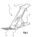
- Figure 1 is a generic device for transmitting a applied in the form of a film to a carrier tape Represented material on a substrate according to the prior art, however only with those important for the invention Share, namely an order foot generally designated 1.
- This order foot 1 is with an order bar 2 equipped to a coated carrier tape 3, the a supply coil, not shown, of the device comes to the order bar 2 is guided. After the transfer of the Layer 4 on a substrate becomes an empty tape 5 Forwarding reel, not shown. With regard on the smooth operation of the device and flawless Transfer of the film to the substrate has been found that such an order foot 1 is not satisfactory is.
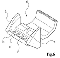
- An inventive foot of an inventive Device is generally designated 6 in the figures.
- This Order foot 6 has band guide ears 7, between which the carrier tape is guided.
- the order foot 6 is with a cantilever arm 9 which is pivotable via a film hinge 8 is articulated on the application foot 6.
- This cantilever arm 9 is at the end as a receiving profile (end section 10) for a clip-like sliding element 15 is formed.
- On the order foot 6 grooves 13 are recessed, which are used in pivoted Position of the cantilever arm 9 a latching engagement to reach the cantilever arm 9 on the order foot 6, which is why Cantilever arm 9 locking cams 12 are provided on both sides.
- the cantilever arm 9 preferably has longitudinal ribs 11. These ribs 11 serve in connection with the choice of an elastic material, e.g. Polyolefin, for securing contacts between the job bar (End section 10) and possible bumps in the Substrate plane. Since the clip-like sliding element 15 made of polytetrafluoroethylene is also elastic, is achieved that even with an uneven substrate, the entire transfer width the band is pressurized and the like an elastic roller reliably prevents blistering is so that a smooth coating on the substrate he follows.
- an elastic material e.g. Polyolefin
- Figures 4 and 5 show the extension arm 9 in the pivoted and locked location.
- the film hinge 8 pivoted about 90 °.
- That on the end portion 10 of the Cantilever arm 9 is a clip-like sliding element 15 additionally fastened in that stop stages 16 and 17 are provided on the application foot 6 or on the cantilever arm 9, whereby the sliding element 15 is secured against rotation.
- By placing the cantilever arm 9 on a traverse 18 of the application foot 6 is achieved that the free end portion 10 of the boom 9 in its entirety compliant can rebound.
- the application foot 6 is in front view with in the grooves 13 latched locking cams 12 and accordingly attached sliding element 15 to recognize.
- Through stops 19 is achieved on the order foot 6 that, if possible, too strong contact pressure if the device is handled improperly the last job bar formed by the sliding element 15 Receives end stop, which is dimensioned so that the Gleicelement 15 still a few tenths of a mm above the contour of the tape guide ears 7 protrudes so that the transfer function always remains secure.
- ends 20 of the clip-like sliding element 15 recessed in recesses 21 of the band guide ears 7 are, which ensures that the carrier tape of the by cutting to length the hose from which the sliding element 15 is preferably manufactured, possibly crushed Ends 20 is kept away.
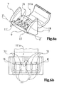
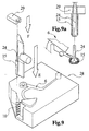
- FIGS. 6a and 6b An alternative embodiment is shown in FIGS. 6a and 6b shown, in which the ribs are designed differently are, these ribs are designated 11 '.
- the ribs 11 ' rise wedge-shaped starting from the sliding element 15 towards the rear and each have a rear wall 11'a, which each in the pivoted position of the cantilever arm 9 on each a stop 31 on the crossbar 18 of the application foot 16 is present.
- the prismatic stops 31 trained so that they together a about circular-shaped contact contour K-K for the rear walls 11'a of the wedge-shaped ribs 11 '.
- This configuration ensures that the ribs 11 ' increasingly biased towards the center of the cantilever arm 9 are and consequently the sliding member 15 against the Substrate level describes a spherical course Z-Z and thus even on uneven surfaces across the entire transfer width a sufficient contact pressure for a bubble-free Transmission is achieved.
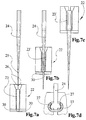
- FIG. 7a to 7d is a very simplified representation a device for producing the clip-like Sliding element 15 shown.
- This device initially shows a pair of pliers 22 which a polytetrafluoroethylene hose section 23 is supplied. This tube section is coming thereby on a ring step 30 of the pliers 22 to the system.
- An im essential conical mandrel 24 with an upstream Knife 25 is moved downward within the pliers 22 starts at the cut, with insertion bevels 26 of the pliers 22 serve as a joining aid (FIG. 7a).
- the holding mandrel 24 has its End position reached.
- the hose section 23 'now has the cross-sectional profile of the end piece 10 of the cantilever arm 9 receive.
- the special ensures Profiling of the holding mandrel 24 in its upper end area, that the cut edges of the clip-like sliding element 15th by stop steps 27 on the upper region of the holding mandrel 24 are held exactly in position.
- FIG. 8 shows the work sequence according to FIGS. 7a to 7c again in isometric representation using a symbolic reproduced device from the hose section 23 until the machined shape of the machined Hose section 23 'or the resulting clip-like Played sliding element 15.
Landscapes
- Adhesive Tape Dispensing Devices (AREA)
- Chemically Coating (AREA)
- Coating Apparatus (AREA)
- Internal Circuitry In Semiconductor Integrated Circuit Devices (AREA)
- Wire Bonding (AREA)
- Liquid Deposition Of Substances Of Which Semiconductor Devices Are Composed (AREA)
- Mechanical Pencils And Projecting And Retracting Systems Therefor, And Multi-System Writing Instruments (AREA)
- Formation Of Insulating Films (AREA)
- Auxiliary Devices For And Details Of Packaging Control (AREA)
Applications Claiming Priority (5)
| Application Number | Priority Date | Filing Date | Title |
|---|---|---|---|
| DE19837573 | 1998-08-19 | ||
| DE19837573 | 1998-08-19 | ||
| DE19859269A DE19859269C2 (de) | 1998-08-19 | 1998-12-22 | Gerät zum Übertragen eines in Form eines Filmes auf ein Trägerband aufgebrachten Stoffes auf ein Substrat |
| DE19859269 | 1998-12-22 | ||
| PCT/EP1999/005787 WO2000010898A1 (de) | 1998-08-19 | 1999-08-10 | Gerät zum übertragen eines in form eines filmes auf ein trägerband aufgebrachten stoffes auf ein substrat |
Publications (2)
| Publication Number | Publication Date |
|---|---|
| EP1105332A1 EP1105332A1 (de) | 2001-06-13 |
| EP1105332B1 true EP1105332B1 (de) | 2003-04-02 |
Family
ID=26048255
Family Applications (1)
| Application Number | Title | Priority Date | Filing Date |
|---|---|---|---|
| EP99944355A Expired - Lifetime EP1105332B1 (de) | 1998-08-19 | 1999-08-10 | Gerät zum übertragen eines in form eines filmes auf ein trägerband aufgebrachten stoffes auf ein substrat |
Country Status (15)
| Country | Link |
|---|---|
| US (2) | US6481485B1 (enExample) |
| EP (1) | EP1105332B1 (enExample) |
| JP (1) | JP2002523318A (enExample) |
| CN (1) | CN1246210C (enExample) |
| AT (1) | ATE236067T1 (enExample) |
| BR (1) | BR9913055A (enExample) |
| CA (1) | CA2341217A1 (enExample) |
| DK (1) | DK1105332T3 (enExample) |
| ES (1) | ES2196851T3 (enExample) |
| ID (1) | ID29809A (enExample) |
| PL (1) | PL189560B1 (enExample) |
| PT (1) | PT1105332E (enExample) |
| RU (1) | RU2204525C2 (enExample) |
| TR (1) | TR200100127T2 (enExample) |
| WO (1) | WO2000010898A1 (enExample) |
Families Citing this family (15)
| Publication number | Priority date | Publication date | Assignee | Title |
|---|---|---|---|---|
| DE10001465C2 (de) * | 2000-01-15 | 2003-11-13 | Pritt Produktionsgesellschaft | Gerät zum Übertragen eines in Form eines Filmes auf ein Trägerband aufgebrachten Stoffes auf ein Substrat |
| US20040047689A1 (en) * | 2001-05-04 | 2004-03-11 | Davis Richard C. | Barrier device and method for building barrier wall |
| DE10214604B4 (de) * | 2002-04-03 | 2005-10-06 | Henkel Kgaa | Gerät zum Übertragen eines in Form eines Filmes auf ein Trägerband aufgebrachten Stoffes auf ein Substrat |
| US6997229B2 (en) * | 2003-09-16 | 2006-02-14 | Sanford, L.P. | Rotatable applicator tip for a corrective tape dispenser |
| US7163040B2 (en) * | 2004-01-13 | 2007-01-16 | Sanford L.P. | Correction tape applicator tip with cylindrical projection |
| US7226521B2 (en) * | 2004-11-03 | 2007-06-05 | The Procter & Gamble Company | Laminae separating dispenser and method of use |
| JP5039662B2 (ja) * | 2008-08-19 | 2012-10-03 | ゼネラル株式会社 | 転写具 |
| US20110042506A1 (en) * | 2009-08-19 | 2011-02-24 | Chien-Lung Wu | Device for Changing Orientation of Tape of Tape Transfer Device |
| US8397784B2 (en) | 2010-08-31 | 2013-03-19 | Sanford, L.P. | Correction tape dispenser with variable clutch mechanism |
| US8578999B2 (en) | 2010-12-29 | 2013-11-12 | Sanford, L.P. | Variable clutch mechanism and correction tape dispenser with variable clutch mechanism |
| US8746313B2 (en) | 2010-12-29 | 2014-06-10 | Sanford, L.P. | Correction tape re-tensioning mechanism and correction tape dispenser comprising same |
| US8746316B2 (en) | 2011-12-30 | 2014-06-10 | Sanford, L.P. | Variable clutch mechanism and correction tape dispenser with variable clutch mechanism |
| FR3046786B1 (fr) | 2016-01-15 | 2018-02-09 | Societe Bic | Dispositif manuel d'application par ruban d'un revetement sur un support presentant un embout d'application ameliore |
| JP6778012B2 (ja) * | 2016-05-09 | 2020-10-28 | プラス株式会社 | 塗膜転写具 |
| CN114193963A (zh) * | 2021-11-12 | 2022-03-18 | 得力集团有限公司 | 一种带芯易复位的修正头及具有该修正头的修正带 |
Family Cites Families (9)
| Publication number | Priority date | Publication date | Assignee | Title |
|---|---|---|---|---|
| US3715941A (en) * | 1971-02-08 | 1973-02-13 | Armstrong Cork Co | Slitting machine |
| US3921482A (en) * | 1974-08-16 | 1975-11-25 | Ree Born Ind | Pipe slitter apparatus |
| US4160398A (en) * | 1975-05-16 | 1979-07-10 | Saint-Gobain Industries | Method and apparatus for manufacture of insulating sleeves |
| US4781782A (en) * | 1987-04-06 | 1988-11-01 | Minnesota Mining And Manufacturing Company | Web applicator |
| DE3736367C1 (de) * | 1987-10-27 | 1989-02-23 | Pelikan Ag | Handgeraet zum UEbertragen eines Filmes von einer Traegerfolie auf ein Substrat |
| DE8813861U1 (de) * | 1988-11-05 | 1988-12-22 | Pelikan Ag, 3000 Hannover | Rutschkupplung zwischen dem Spulenkern einer Wickelspule eines Bürogerätes o.dgl. und einem zu diesem konzentrisch angeordneten Antriebs- oder Getrieberad |
| DE3900156A1 (de) * | 1989-01-04 | 1990-07-05 | Czewo Plast Kunststofftech | Vorrichtung zum auftragen eines klebstoffilms |
| US4957022A (en) * | 1989-03-03 | 1990-09-18 | Phillips Petroleum Company | Pipe slitter |
| EP0742111A3 (en) * | 1991-10-02 | 1997-09-24 | Fuji Kagaku Shikogyo | Color film transfer device |
-
1999
- 1999-08-10 CA CA 2341217 patent/CA2341217A1/en not_active Abandoned
- 1999-08-10 PT PT99944355T patent/PT1105332E/pt unknown
- 1999-08-10 TR TR200100127T patent/TR200100127T2/xx unknown
- 1999-08-10 PL PL99345801A patent/PL189560B1/pl not_active IP Right Cessation
- 1999-08-10 WO PCT/EP1999/005787 patent/WO2000010898A1/de not_active Ceased
- 1999-08-10 DK DK99944355T patent/DK1105332T3/da active
- 1999-08-10 CN CNB998097497A patent/CN1246210C/zh not_active Expired - Fee Related
- 1999-08-10 AT AT99944355T patent/ATE236067T1/de not_active IP Right Cessation
- 1999-08-10 ES ES99944355T patent/ES2196851T3/es not_active Expired - Lifetime
- 1999-08-10 JP JP2000566178A patent/JP2002523318A/ja active Pending
- 1999-08-10 ID ID20010402D patent/ID29809A/id unknown
- 1999-08-10 RU RU2001107145A patent/RU2204525C2/ru not_active IP Right Cessation
- 1999-08-10 BR BR9913055A patent/BR9913055A/pt not_active IP Right Cessation
- 1999-08-10 EP EP99944355A patent/EP1105332B1/de not_active Expired - Lifetime
- 1999-08-10 US US09/763,427 patent/US6481485B1/en not_active Expired - Fee Related
-
2002
- 2002-11-15 US US10/295,312 patent/US6792664B2/en not_active Expired - Fee Related
Also Published As
| Publication number | Publication date |
|---|---|
| CN1246210C (zh) | 2006-03-22 |
| TR200100127T2 (tr) | 2001-06-21 |
| CN1312767A (zh) | 2001-09-12 |
| JP2002523318A (ja) | 2002-07-30 |
| US20030066612A1 (en) | 2003-04-10 |
| PL345801A1 (en) | 2002-01-02 |
| RU2204525C2 (ru) | 2003-05-20 |
| ATE236067T1 (de) | 2003-04-15 |
| WO2000010898A1 (de) | 2000-03-02 |
| US6481485B1 (en) | 2002-11-19 |
| EP1105332A1 (de) | 2001-06-13 |
| PL189560B1 (pl) | 2005-08-31 |
| DK1105332T3 (da) | 2003-07-21 |
| HK1036789A1 (en) | 2002-01-18 |
| ID29809A (id) | 2001-10-11 |
| ES2196851T3 (es) | 2003-12-16 |
| PT1105332E (pt) | 2003-08-29 |
| BR9913055A (pt) | 2001-05-08 |
| US6792664B2 (en) | 2004-09-21 |
| CA2341217A1 (en) | 2000-03-02 |
Similar Documents
| Publication | Publication Date | Title |
|---|---|---|
| EP1105332B1 (de) | Gerät zum übertragen eines in form eines filmes auf ein trägerband aufgebrachten stoffes auf ein substrat | |
| DE69003115T2 (de) | Spender zum auftragen eines haftmaterials auf eine unterlage. | |
| DE60105613T2 (de) | Klebestreifen-Anbringeinheit für eine Pappschachtel-Klebestreifen-Anbringmaschine | |
| DE3506947A1 (de) | Schlauch-bandfoerderer | |
| EP3558547B1 (de) | Klebebandabroller mit umlenkeinrichtung | |
| EP1105331B1 (de) | Gerät zum übertragen eines in form eines filmes auf ein trägerband aufgebrachten stoffes auf ein substrat | |
| DE102011088342B4 (de) | Kreuzwickelvorrichtung | |
| DE8902452U1 (de) | Gerät zum Anbringen von Abdeckmaterial | |
| EP0873957B1 (de) | Vorrichtung zum Schneiden einer Papierbahn und zum Anbringen eines Klebebandes an der Schnittkante der Papierbahn | |
| DE10001465C2 (de) | Gerät zum Übertragen eines in Form eines Filmes auf ein Trägerband aufgebrachten Stoffes auf ein Substrat | |
| EP0117232A2 (de) | Vorrichtung zur Applikation eines Klebstoffbandes um den Rand eines Blechformteiles | |
| DE20117063U1 (de) | Schneidvorrichtung und Schälwerkzeug zum Abschälen einer äußeren Schicht oder Schichten eines Rohres oder Kabels | |
| DE4120031C1 (en) | Glue transferring device - has frame with band reel and divider which is varied as function of reel diameter so distance of cutting of reel from outside of band car be varied | |
| DE19859269A1 (de) | Gerät zum Übertragen eines in Form eines Filmes auf ein Trägerband aufgebrachten Stoffes auf ein Substrat | |
| DE10085486B4 (de) | Bandaufbringvorrichtung | |
| DE3905694C1 (en) | Device for cutting open a cable sheath | |
| DE19920725B4 (de) | Spanneinheit | |
| EP1220759B1 (de) | Montagevorrichtung | |
| DE69103735T2 (de) | Vorrichtung zum Schneiden von ungleichmässig geformten Enden von Holzfurnier und zum Zusammenkleben der Furniere an den schrägen Endflächen, die durch das Schneiden gebildet wurden. | |
| DE10112636B4 (de) | Verfahren und Vorrichtung zur Klebestellenvorbereitung einer Materialrolle | |
| DE3329238C2 (de) | Handetikettiergerät | |
| WO2002055423A1 (de) | Gerät zum übertragen eines in form eines filmes auf ein trägerband aufgebrachten stoffes auf ein substrat | |
| DE19920724C1 (de) | Umlenkaggregat | |
| WO1999037569A1 (de) | Gerät zum übertragen eines filmes von einem trägerband auf ein substrat | |
| DE2604128A1 (de) | Geraet zum rasieren oder dergleichen |
Legal Events
| Date | Code | Title | Description |
|---|---|---|---|
| PUAI | Public reference made under article 153(3) epc to a published international application that has entered the european phase |
Free format text: ORIGINAL CODE: 0009012 |
|
| 17P | Request for examination filed |
Effective date: 20010212 |
|
| AK | Designated contracting states |
Kind code of ref document: A1 Designated state(s): AT BE CH CY DE DK ES FI FR GB GR IE IT LI LU MC NL PT SE |
|
| GRAH | Despatch of communication of intention to grant a patent |
Free format text: ORIGINAL CODE: EPIDOS IGRA |
|
| GRAH | Despatch of communication of intention to grant a patent |
Free format text: ORIGINAL CODE: EPIDOS IGRA |
|
| GRAA | (expected) grant |
Free format text: ORIGINAL CODE: 0009210 |
|
| AK | Designated contracting states |
Designated state(s): AT BE CH CY DE DK ES FI FR GB GR IE IT LI LU MC NL PT SE |
|
| REG | Reference to a national code |
Ref country code: GB Ref legal event code: FG4D Free format text: NOT ENGLISH |
|
| REG | Reference to a national code |
Ref country code: CH Ref legal event code: EP |
|
| REG | Reference to a national code |
Ref country code: IE Ref legal event code: FG4D Free format text: GERMAN |
|
| REF | Corresponds to: |
Ref document number: 59904866 Country of ref document: DE Date of ref document: 20030508 Kind code of ref document: P |
|
| REG | Reference to a national code |
Ref country code: GR Ref legal event code: EP Ref document number: 20030401890 Country of ref document: GR |
|
| REG | Reference to a national code |
Ref country code: SE Ref legal event code: TRGR |
|
| REG | Reference to a national code |
Ref country code: DK Ref legal event code: T3 |
|
| GBT | Gb: translation of ep patent filed (gb section 77(6)(a)/1977) | ||
| REG | Reference to a national code |
Ref country code: IE Ref legal event code: FD4D Ref document number: 1105332E Country of ref document: IE |
|
| REG | Reference to a national code |
Ref country code: ES Ref legal event code: FG2A Ref document number: 2196851 Country of ref document: ES Kind code of ref document: T3 |
|
| ET | Fr: translation filed | ||
| PLBE | No opposition filed within time limit |
Free format text: ORIGINAL CODE: 0009261 |
|
| STAA | Information on the status of an ep patent application or granted ep patent |
Free format text: STATUS: NO OPPOSITION FILED WITHIN TIME LIMIT |
|
| 26N | No opposition filed |
Effective date: 20040105 |
|
| REG | Reference to a national code |
Ref country code: IE Ref legal event code: ERR Free format text: EUROPEAN PATENTS DESIGNATING IRELAND TREATED AS ALWAYS HAVING BEEN VOID IN ACCORDANCE WITH SECTION 119(7) IN JOURNAL NUMBER 1982, PAGE 2259 EUROPEAN PATENT NUMBER 1105332 WAS ADVERTISED IN ERROR AS ALWAYS HAVING BEEN VOID. |
|
| PGFP | Annual fee paid to national office [announced via postgrant information from national office to epo] |
Ref country code: PT Payment date: 20060629 Year of fee payment: 8 |
|
| PGFP | Annual fee paid to national office [announced via postgrant information from national office to epo] |
Ref country code: GR Payment date: 20060714 Year of fee payment: 8 |
|
| PGFP | Annual fee paid to national office [announced via postgrant information from national office to epo] |
Ref country code: CY Payment date: 20060721 Year of fee payment: 8 |
|
| PGFP | Annual fee paid to national office [announced via postgrant information from national office to epo] |
Ref country code: MC Payment date: 20060727 Year of fee payment: 8 |
|
| PGFP | Annual fee paid to national office [announced via postgrant information from national office to epo] |
Ref country code: NL Payment date: 20060803 Year of fee payment: 8 |
|
| PGFP | Annual fee paid to national office [announced via postgrant information from national office to epo] |
Ref country code: FR Payment date: 20060808 Year of fee payment: 8 |
|
| PGFP | Annual fee paid to national office [announced via postgrant information from national office to epo] |
Ref country code: GB Payment date: 20060809 Year of fee payment: 8 |
|
| PGFP | Annual fee paid to national office [announced via postgrant information from national office to epo] |
Ref country code: LU Payment date: 20060810 Year of fee payment: 8 |
|
| PGFP | Annual fee paid to national office [announced via postgrant information from national office to epo] |
Ref country code: AT Payment date: 20060811 Year of fee payment: 8 |
|
| PGFP | Annual fee paid to national office [announced via postgrant information from national office to epo] |
Ref country code: IE Payment date: 20060814 Year of fee payment: 8 Ref country code: FI Payment date: 20060814 Year of fee payment: 8 |
|
| PGFP | Annual fee paid to national office [announced via postgrant information from national office to epo] |
Ref country code: DK Payment date: 20060815 Year of fee payment: 8 Ref country code: CH Payment date: 20060815 Year of fee payment: 8 |
|
| PGFP | Annual fee paid to national office [announced via postgrant information from national office to epo] |
Ref country code: IT Payment date: 20060831 Year of fee payment: 8 |
|
| PGFP | Annual fee paid to national office [announced via postgrant information from national office to epo] |
Ref country code: ES Payment date: 20060921 Year of fee payment: 8 |
|
| PGFP | Annual fee paid to national office [announced via postgrant information from national office to epo] |
Ref country code: BE Payment date: 20061016 Year of fee payment: 8 |
|
| PGFP | Annual fee paid to national office [announced via postgrant information from national office to epo] |
Ref country code: SE Payment date: 20060804 Year of fee payment: 8 |
|
| REG | Reference to a national code |
Ref country code: PT Ref legal event code: MM4A Free format text: LAPSE DUE TO NON-PAYMENT OF FEES Effective date: 20080211 |
|
| BERE | Be: lapsed |
Owner name: *PRITT PRODUKTIONSG.- M.B.H. Effective date: 20070831 |
|
| EUG | Se: european patent has lapsed | ||
| REG | Reference to a national code |
Ref country code: CH Ref legal event code: PL |
|
| REG | Reference to a national code |
Ref country code: DK Ref legal event code: EBP |
|
| GBPC | Gb: european patent ceased through non-payment of renewal fee |
Effective date: 20070810 |
|
| PG25 | Lapsed in a contracting state [announced via postgrant information from national office to epo] |
Ref country code: SE Free format text: LAPSE BECAUSE OF NON-PAYMENT OF DUE FEES Effective date: 20070811 Ref country code: NL Free format text: LAPSE BECAUSE OF NON-PAYMENT OF DUE FEES Effective date: 20080301 Ref country code: MC Free format text: LAPSE BECAUSE OF NON-PAYMENT OF DUE FEES Effective date: 20070831 Ref country code: LI Free format text: LAPSE BECAUSE OF NON-PAYMENT OF DUE FEES Effective date: 20070831 Ref country code: CH Free format text: LAPSE BECAUSE OF NON-PAYMENT OF DUE FEES Effective date: 20070831 |
|
| NLV4 | Nl: lapsed or anulled due to non-payment of the annual fee |
Effective date: 20080301 |
|
| PG25 | Lapsed in a contracting state [announced via postgrant information from national office to epo] |
Ref country code: PT Free format text: LAPSE BECAUSE OF NON-PAYMENT OF DUE FEES Effective date: 20080211 Ref country code: FI Free format text: LAPSE BECAUSE OF NON-PAYMENT OF DUE FEES Effective date: 20070810 |
|
| REG | Reference to a national code |
Ref country code: IE Ref legal event code: MM4A |
|
| PG25 | Lapsed in a contracting state [announced via postgrant information from national office to epo] |
Ref country code: AT Free format text: LAPSE BECAUSE OF NON-PAYMENT OF DUE FEES Effective date: 20070810 Ref country code: CY Free format text: LAPSE BECAUSE OF NON-PAYMENT OF DUE FEES Effective date: 20070810 |
|
| REG | Reference to a national code |
Ref country code: FR Ref legal event code: ST Effective date: 20080430 |
|
| PG25 | Lapsed in a contracting state [announced via postgrant information from national office to epo] |
Ref country code: DK Free format text: LAPSE BECAUSE OF NON-PAYMENT OF DUE FEES Effective date: 20070831 |
|
| PG25 | Lapsed in a contracting state [announced via postgrant information from national office to epo] |
Ref country code: BE Free format text: LAPSE BECAUSE OF NON-PAYMENT OF DUE FEES Effective date: 20070831 |
|
| PG25 | Lapsed in a contracting state [announced via postgrant information from national office to epo] |
Ref country code: IE Free format text: LAPSE BECAUSE OF NON-PAYMENT OF DUE FEES Effective date: 20070810 Ref country code: FR Free format text: LAPSE BECAUSE OF NON-PAYMENT OF DUE FEES Effective date: 20070831 |
|
| REG | Reference to a national code |
Ref country code: ES Ref legal event code: FD2A Effective date: 20070811 |
|
| PG25 | Lapsed in a contracting state [announced via postgrant information from national office to epo] |
Ref country code: GB Free format text: LAPSE BECAUSE OF NON-PAYMENT OF DUE FEES Effective date: 20070810 |
|
| PG25 | Lapsed in a contracting state [announced via postgrant information from national office to epo] |
Ref country code: GR Free format text: LAPSE BECAUSE OF NON-PAYMENT OF DUE FEES Effective date: 20080304 Ref country code: ES Free format text: LAPSE BECAUSE OF NON-PAYMENT OF DUE FEES Effective date: 20070811 |
|
| PG25 | Lapsed in a contracting state [announced via postgrant information from national office to epo] |
Ref country code: LU Free format text: LAPSE BECAUSE OF NON-PAYMENT OF DUE FEES Effective date: 20070810 |
|
| PG25 | Lapsed in a contracting state [announced via postgrant information from national office to epo] |
Ref country code: IT Free format text: LAPSE BECAUSE OF NON-PAYMENT OF DUE FEES Effective date: 20070810 |
|
| PGFP | Annual fee paid to national office [announced via postgrant information from national office to epo] |
Ref country code: DE Payment date: 20140806 Year of fee payment: 16 |
|
| REG | Reference to a national code |
Ref country code: DE Ref legal event code: R119 Ref document number: 59904866 Country of ref document: DE |
|
| PG25 | Lapsed in a contracting state [announced via postgrant information from national office to epo] |
Ref country code: DE Free format text: LAPSE BECAUSE OF NON-PAYMENT OF DUE FEES Effective date: 20160301 |