EP1096096B1 - Procédé de montage d'un élément de paroi - Google Patents
Procédé de montage d'un élément de paroi Download PDFInfo
- Publication number
- EP1096096B1 EP1096096B1 EP00123312A EP00123312A EP1096096B1 EP 1096096 B1 EP1096096 B1 EP 1096096B1 EP 00123312 A EP00123312 A EP 00123312A EP 00123312 A EP00123312 A EP 00123312A EP 1096096 B1 EP1096096 B1 EP 1096096B1
- Authority
- EP
- European Patent Office
- Prior art keywords
- frame
- frame portions
- masonry
- connecting elements
- stock
- Prior art date
- Legal status (The legal status is an assumption and is not a legal conclusion. Google has not performed a legal analysis and makes no representation as to the accuracy of the status listed.)
- Expired - Lifetime
Links
- 238000000034 method Methods 0.000 title claims description 24
- 238000007789 sealing Methods 0.000 claims description 7
- 238000010276 construction Methods 0.000 description 4
- 238000011161 development Methods 0.000 description 4
- 230000018109 developmental process Effects 0.000 description 4
- 238000003780 insertion Methods 0.000 description 3
- 230000037431 insertion Effects 0.000 description 3
- 238000003825 pressing Methods 0.000 description 3
- 238000004026 adhesive bonding Methods 0.000 description 2
- 239000006260 foam Substances 0.000 description 2
- 238000009434 installation Methods 0.000 description 2
- 230000003319 supportive effect Effects 0.000 description 2
- 229910000831 Steel Inorganic materials 0.000 description 1
- 230000015572 biosynthetic process Effects 0.000 description 1
- 239000002131 composite material Substances 0.000 description 1
- 230000006835 compression Effects 0.000 description 1
- 238000007906 compression Methods 0.000 description 1
- 239000000428 dust Substances 0.000 description 1
- 239000011521 glass Substances 0.000 description 1
- 239000003292 glue Substances 0.000 description 1
- 239000000463 material Substances 0.000 description 1
- 230000013011 mating Effects 0.000 description 1
- 239000002184 metal Substances 0.000 description 1
- 239000011505 plaster Substances 0.000 description 1
- 238000009419 refurbishment Methods 0.000 description 1
- 238000009418 renovation Methods 0.000 description 1
- 239000007787 solid Substances 0.000 description 1
- 239000010959 steel Substances 0.000 description 1
- 239000002023 wood Substances 0.000 description 1
Images


Classifications
-
- E—FIXED CONSTRUCTIONS
- E06—DOORS, WINDOWS, SHUTTERS, OR ROLLER BLINDS IN GENERAL; LADDERS
- E06B—FIXED OR MOVABLE CLOSURES FOR OPENINGS IN BUILDINGS, VEHICLES, FENCES OR LIKE ENCLOSURES IN GENERAL, e.g. DOORS, WINDOWS, BLINDS, GATES
- E06B3/00—Window sashes, door leaves, or like elements for closing wall or like openings; Layout of fixed or moving closures, e.g. windows in wall or like openings; Features of rigidly-mounted outer frames relating to the mounting of wing frames
- E06B3/96—Corner joints or edge joints for windows, doors, or the like frames or wings
- E06B3/984—Corner joints or edge joints for windows, doors, or the like frames or wings specially adapted for frame members of wood or other material worked in a similar way
-
- E—FIXED CONSTRUCTIONS
- E06—DOORS, WINDOWS, SHUTTERS, OR ROLLER BLINDS IN GENERAL; LADDERS
- E06B—FIXED OR MOVABLE CLOSURES FOR OPENINGS IN BUILDINGS, VEHICLES, FENCES OR LIKE ENCLOSURES IN GENERAL, e.g. DOORS, WINDOWS, BLINDS, GATES
- E06B1/00—Border constructions of openings in walls, floors, or ceilings; Frames to be rigidly mounted in such openings
- E06B1/04—Frames for doors, windows, or the like to be fixed in openings
- E06B1/34—Coverings, e.g. protecting against weather, for decorative purposes
- E06B1/345—Renovation window frames covering the existing old frames
-
- E—FIXED CONSTRUCTIONS
- E06—DOORS, WINDOWS, SHUTTERS, OR ROLLER BLINDS IN GENERAL; LADDERS
- E06B—FIXED OR MOVABLE CLOSURES FOR OPENINGS IN BUILDINGS, VEHICLES, FENCES OR LIKE ENCLOSURES IN GENERAL, e.g. DOORS, WINDOWS, BLINDS, GATES
- E06B3/00—Window sashes, door leaves, or like elements for closing wall or like openings; Layout of fixed or moving closures, e.g. windows in wall or like openings; Features of rigidly-mounted outer frames relating to the mounting of wing frames
- E06B3/96—Corner joints or edge joints for windows, doors, or the like frames or wings
- E06B3/964—Corner joints or edge joints for windows, doors, or the like frames or wings using separate connection pieces, e.g. T-connection pieces
- E06B3/9642—Butt type joints with at least one frame member cut off square; T-shape joints
-
- F—MECHANICAL ENGINEERING; LIGHTING; HEATING; WEAPONS; BLASTING
- F16—ENGINEERING ELEMENTS AND UNITS; GENERAL MEASURES FOR PRODUCING AND MAINTAINING EFFECTIVE FUNCTIONING OF MACHINES OR INSTALLATIONS; THERMAL INSULATION IN GENERAL
- F16B—DEVICES FOR FASTENING OR SECURING CONSTRUCTIONAL ELEMENTS OR MACHINE PARTS TOGETHER, e.g. NAILS, BOLTS, CIRCLIPS, CLAMPS, CLIPS OR WEDGES; JOINTS OR JOINTING
- F16B12/00—Jointing of furniture or the like, e.g. hidden from exterior
- F16B12/44—Leg joints; Corner joints
- F16B12/46—Non-metal corner connections
- F16B2012/466—Non-metal corner connections using mortise and tenon joints
Definitions
- the invention relates generally to a method of mounting a frame stock for wall elements.
- Under wall element is mainly a window or a door understood, but the invention is also applicable to panel segments, composite facades or the like.
- a slightly improved way to replace basic elements in need of refurbishment is to cut out the old frame stock along the masonry so that a remnant of the old frame stock remains in the masonry, and then insert a smaller frame stock into the resulting opening.
- This method has the disadvantage that, firstly, a smaller wall element must be used, which typically amounts to a loss of up to 10% of the original window area and a corresponding loss of light in the case of windows.
- Second has it has the disadvantage that the remaining in the wall rest of the old frame stock still needs to be fully functional for further use. However, this is often not the case when replacing renovation-requiring wall elements.
- Frame sticks used in such cases may be of the type illustrated in Figs. 1, 1a and 1b.
- DD 202 333 discloses a Gehrungseckitati for assembled from profiled bars frame.
- the disclosed corner joint comprises groove cuts running along a miter cutting edge, into which a clamping part is inserted, which contracts the profile bars and presses them together in the miter plane. Due to the miter, the corner joint of the DD 202 333 do not use to replace existing wall elements without disassembling the surrounding structures of the same size.
- the device consists of a twin mounting piece, which can be introduced under force into two blind holes of corresponding shape. Of the blind holes are each one in the edge region of one of two mitred cut frame parts.
- the describes NL 6614322 a mounting arrangement for a light opening in a wall, wherein a conical clamping block attached to a frame element list.
- the clamping block is brought into engagement by displacing a second frame element with a recess formed therein.
- the shows DE 90 12 237 U1 a window frame in which the legs abut each other at the corners butt, wherein at the end of each of the abutting legs, a rod is attached, which at the end of the respective engages other leg and can be fixed by a screw at this end.
- this object is achieved by a method for mounting a frame stock with the features of claim 1.
- the present invention is based on the idea not to put together frame parts of a frame stock from the outside, but to mount a frame stick for a wall element from the inside to the outside of the wall element.
- fasteners for fixing a plurality of frame members in position relative to each other such that they do not interfere with relative movement of the frame members to the final shape of the frame stock and at the same time interconnect the individual frame members of the frame stock.
- masonry is an example of the material surrounding the frame stick in its usual installation situation at least in certain areas. Also solid wood or steel facades, glass walls or similar. are therefore covered by the term masonry.
- the present invention provides significant advantages.
- the surface of a wall element to be exchanged not only fully preserved, but can also be increased depending on the construction of the new frame stock relative to the old frame stock.
- the construction and dismantling of external scaffolding can be omitted because working from the inside of a building is possible, and in a typical application is also a re-plastering of the masonry and an exchange of Wallpaper or the like not necessary.
- the frame stick and method according to the present invention thus lead to considerable savings in terms of time, labor and costs.
- connection elements in the mounted state of the frame stock, is positively received in corresponding receptacles of the one or more of the connecting elements in their position fixed to each other frame parts.
- this development of the invention offers the advantage that a positional fixation of the frame parts in the essential directions is automatically achieved during the assembly movement from the inside to the outside, without further measures being necessary.
- a frictional connection may be provided in this case, in order to achieve a positional fixation against the mounting direction.
- the receptacles are substantially perpendicular to the longitudinal extent of the lower or upper frame part and parallel to the longitudinal extent of the two other frame parts, but on sides of the frame parts, which are the outer sides of the frame stock in the assembled state of the frame stock. In this way, a clearly defined stop can be provided during assembly of the frame parts, which is independent of the surrounding masonry. A later access to the connecting elements and thus an additional mounting option is also provided.
- Such additional supportive fastening options can by gluing, screwing, riveting or pressing the connecting elements with the respective frame parts, or even the frame parts together be provided. This corresponds to a preferred embodiment of the invention.
- the wall elements in which the frame stock is used be rectangular. Accordingly, it is provided that the frame stock has four in the assembled state arranged at right angles frame parts. Such an arrangement also simplifies the assembly process.
- the frame stock comes with a single connection element for fixing two frame parts.
- connecting elements with a dovetail-shaped or 8-shaped cross-section.
- the frame stock has bores and / or grooves for introducing a sealing means in the frame parts.
- the method according to the invention comprises that steps (d) and (e) are carried out successively for each of the two further frame parts, e.g. if due to tolerances in the installation dimensions or residues of the old frame stock together with any previously existing sealing means should result in a force during assembly, which makes the simultaneous introduction of the two other frame parts between the lower and the upper frame part difficult.
- the assembly is further simplified if the force required for introducing the or the other frame parts between the lower and the upper frame part is gradually increased, Therefore, according to a development of the method according to the invention, provision is made for the further frame parts to be introduced in the middle region of the longitudinal extension of the lower and / or the upper frame part.
- the frame stock 1 consists of individual frame parts 2, 3, 4, 5, which are usually arranged at right angles to each other.
- the frame stock is shown in all illustrated embodiments as four frame parts and is shown of rectangular basic shape, also rectangular shapes with more than four frame parts and other polygonal shapes are conceivable, for example, hexagons or octagons.
- the frame stock 1 in Fig. 2 comprises fastening elements 6, which allow a positional fixation of the frame parts 2, 3, 4, 5 relative to each other.
- fastening elements 6 protrude from the frame plane, as well as from Figs. 3a, 3b and 3c better apparent.
- These connecting elements 6 can be made in one piece with the frame part, which is particularly suitable for plastic wall elements, or be introduced as separate parts in corresponding recesses, such as milled grooves.
- the latter embodiment is particularly suitable for wooden wall elements, and the fit by the introduction of the connecting elements 6 in corresponding recesses may be supported by a glue.
- connection of the frame parts 2, 3, 4, 5 with the connecting elements 6 is z.
- the connecting elements 6 are shown in Fig. 2 in a cross-sectional shape as a dovetail, but may be embodied in a variety of different forms, which can be provided via these connecting elements also stop surfaces, the movement of the parallel frame parts 3, 5 over the end of the frame parts 2, 4 prevent.
- FIGS. 2 and 3a, 3b, 3c represent a multi-part embodiment of frame parts 2, 3, 4, 5 and connecting elements 6, in the exemplary embodiment according to FIG. 4 an integral construction is shown.
- the upper and lower frame parts 2, 4 web-like projections 7 as a connecting element.
- a fixing of the frame part 3 and the frame parts 2, 4 in Fig. 4 can be achieved by the frame part 3 accurately inserted into the gap between the frame parts 2, 4 and then in the direction of the arrows in Fig. 4 along the longitudinal extent of the frame parts. 2 , 4 is moved.
- the web-like connecting elements 7 are received in correspondingly shaped receptacles 17, where they provide a positive locking and possibly additionally by adhesion a positional fixation between the frame parts 2, 4 on the one hand and the frame part 3 on the other.
- the positive connection can be achieved by a certain excess of the connecting elements 7 relative to the receptacles 17, so that a secure connection is provided by pressing, or possibly by gluing or the like ..
- FIG. 5 shows a further example in which both the connecting elements 8 of the frame parts 2, 4 and the corresponding receptacles 18 on the frame part 3 are each made in two parts.
- insertion flaps 8 'are introduced in the arrow direction in corresponding recesses on the frame parts and fastened there. Accordingly, the procedure with frame part 3, in the insertion flaps 8 'are inserted and secured with recesses 18.
- the further procedure corresponds to the illustration in FIG. 4.
- FIG. 6 an embodiment is shown, in which the connecting elements 9 have an 8-shape, and in the frame part 3 recesses are incorporated, which correspond in its cross section to a segment of the form "8".
- connecting elements of a further cross-sectional shape are shown and designated in the Fig. 10.
- the connecting elements 10 of FIG. 7 have a double T-shape in cross-section, so that they can be inserted with the one transverse bar of the "T" into corresponding recesses of the frame parts 2, 4, and with half of the longitudinal bar and the second Project the crossbeams of the "T" over the frame levels.
- corresponding T-shaped recesses 20 are provided which fit to the over the frame plane projecting part of the connecting elements 10. The fixing of the frame part 3 to the frame parts 2, 4 takes place as in the previous embodiments.
- the length of the fastening elements 7, 8, 9 (corresponding to FIGS. 4, 5, 6) and the fastening elements 10 (FIG. 9) is typically equal to or smaller than the width of the frame element 3, so that in the assembled state of the frame stock the fastening elements of the inside of the frame stock 1 on the one hand are not visible, and on the other hand represent no hindrance to the assembly of a window sash or the like.
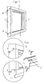
- FIG. 8 a possibility of fixing the position of the frame part 3 to the frame parts 2, 4 via L-shaped connecting elements 11 is shown.
- the connecting elements 11 are substantially attached to the frame parts 2, 4, that they are perpendicular to the longitudinal extent, at right angles to the outside of the mounted frame stock protrude to the longitudinal extent and form a stop for the frame part 3.
- the frame part 3 is provided with corresponding receptacles 21 for these protruding parts of the connecting elements 11 which extend parallel to the longitudinal extent of the frame part 3.
- the profile shape of the frame parts 2, 3 and 4 allows a precise insertion and movement of the frame part 3 along the longitudinal extent of the frame parts 2, 4 until the connecting elements 11 come into contact with the receptacles 21.
- the attachment can be optimized via screw connections, which is shown in Fig. 8 via corresponding openings.
- the screwing can be made possible via a machine thread in the connecting elements 11 and be performed from the inside of the frame stock.
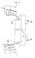
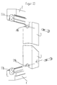
- FIGS. 12 and 13 respectively show a dovetail-shaped formation of connecting elements 11a, and an 8-shaped embodiment of connecting element 11b (Rampa sleeve).
- the fastening elements 11a, 11b are fastened to the frame parts 2, 4 substantially at right angles to the longitudinal extent of the frame parts 2, 4 via a suitable fastening means, for example a riveting or screw connection.
- Recesses 21a, 21b are incorporated on the frame part 3, substantially parallel to the longitudinal extent of the frame part 3 from the front side of the frame part 3.
- the receptacles 21a, 21b in the frame part 3 correspond in their cross-sectional shape to the part of the connecting elements 11a, 11b projecting from the frame plane.
- a change in position along the direction of the frame parts 2, 4 can be achieved either by a certain oversize and resulting compression of the part of the connecting elements 11a, 11b projecting from the frame plane relative to the receptacles 21a, 21b assigned to it, but it is also possible to to use additional fasteners, as shown in FIGS. 12 and 13.
- FIGS. 9, 10 and 11 illustrate the method according to the invention as follows.
- FIG. 9 shows a frame stock to be exchanged, in which only the frame parts bear the same reference numerals in order to simplify the illustration.
- a frame stock is usually surrounded by a masonry, so that the exact outer dimensions of the frame stick from the outside are not readily apparent.
- first spy holes 12 are introduced into the exchanged frame stock, whereupon standard profiles can be cut to size for the new frame stock.
- bores 13 and grooves 14 are preferably introduced into the new frame stock 1 (FIG. 10).
- the old window can be removed without damaging the surrounding masonry, for example by cutting and breaking.
- the lower frame part 4 of the new frame stock 1 (FIG. 11) is inserted into the resulting recess in the masonry and fixed, for example screwed.
- the upper frame part 2 is inserted into the also resulting from the removal of the old frame stock recess in the masonry, where it is not completely fixed to the masonry is only secured against falling.
- FIG. 11 the fastening elements 6 and the receptacles 16 according to the exemplary embodiment of FIGS. 2, 3a, 3b and 3c are shown by way of example.
- the mating surfaces of the connecting elements can be glued supportive - usually in wooden frame sticks, but the connecting element can also be screwed - typically plastic or light metal frame sticks.
- the lateral frame parts 3, 5 and the upper frame part 2 are fixed to the masonry, i. firmly connected to him, for example by dowels or construction screws, and it is through the holes 13 (Fig. 10) introduced a suitable seal, for example, sealing foam.
- a suitable seal for example, sealing foam.
- the sealing foam can be evenly distributed along the grooves 14 (FIG. 10) around the newly inserted frame stock 1, whereby an optimal seal can be achieved.
Landscapes
- Engineering & Computer Science (AREA)
- Civil Engineering (AREA)
- Structural Engineering (AREA)
- Door And Window Frames Mounted To Openings (AREA)
- Supply And Installment Of Electrical Components (AREA)
- Joining Of Building Structures In Genera (AREA)
- Body Structure For Vehicles (AREA)
- Conveying And Assembling Of Building Elements In Situ (AREA)
Claims (8)
- Procédé de montage d'un élément de paroi fait de plusieurs éléments de cadre dans un ouvrage de maçonnerie ou équivalent comprenant les étapes suivantes :a) poser un élément de cadre (4) inférieur dans l'ouvrage de maçonnerie et fixer cet élément de cadre à l'ouvrage de maçonnerie, l'élément de cadre inférieur étant muni d'un élément de liaison ;b) poser un élément de cadre supérieur (2) dans l'ouvrage de maçonnerie, l'élément de cadre supérieur étant positionné, dans l'état monté de l'élément de paroi, à l'opposé du premier élément de cadre et étant muni d'un élément de liaison ;c) protéger de l'élément de cadre supérieur (2) contre la chute ;d) poser deux autres éléments de cadre (3, 5) entre l'élément de cadre inférieur (4) et l'élément de cadre supérieur (2) ;e) déplacer autres éléments de cadre (3, 5) le long de l'étendue longitudinale de l'élément de cadre supérieur (4) et/ou de l'élément de cadre inférieur (2) jusqu'à ce que les éléments de liaison de l'élément de cadre inférieur et/ou de l'élément de cadre supérieur soient mis en prise avec des logements dans les autres éléments de cadre (3, 5).
- Procédé selon la revendication 1, caractérisé en ce que des étapes (d) et (e) sont réalisées, plusieurs fois, l'une après l'autre, pour chacun des deux autres éléments de cadre (3, 5).
- Procédé selon la revendication 1 ou 2, caractérisé en ce que dans l'étape (d), les deux autres éléments de cadre (3, 5) sont posés entre l'élément de cadre inférieur (4) et l'élément de cadre supérieur dans la zone médiane de l'étendue longitudinale de l'élément de cadre inférieur et/ou de l'élément de cadre supérieur.
- Procédé selon au moins une des revendications 1 à 3, caractérisé en ce que dans une étape(f) l'élément de cadre supérieur et les deux autres éléments de cadre sont fixés à l'ouvrage de maçonnerie.
- Procédé selon au moins une des revendications 1 à 4, caractérisé en ce que les éléments de liaison de l'élément de cadre inférieur et/ou supérieur sont collés, vissés, rivés ou pressés avec les deux autres éléments de cadre.
- Procédé selon au moins une des revendications 1 à 5, caractérisé en ce que dans une autre étape(g) un composant pour joint est posé entre l'élément de paroi et l'ouvrage de maçonnerie par des perçages et/ou des rainures dans au moins un des éléments de cadre.
- Procédé selon au moins une des revendications 1 à 6, caractérisé en ce que les éléments de liaison présentent une coupe transversale en queue d'aronde ou en forme de 8.
- Procédé selon au moins une des revendications 1 à 7, caractérisé en ce que les logements (21, 21 a, 21 b) sont placés pour l'essentiel perpendiculairement à l'étendue longitudinale des éléments de cadre inférieur et supérieur (2, 4) et parallèlement à l'étendue longitudinale des deux autres éléments de cadre (3, 5), sur les côtés des éléments de cadre, qui sont, dans l'état monté de l'élément de paroi (1), les cotés extérieurs de l'élément de paroi
Priority Applications (2)
| Application Number | Priority Date | Filing Date | Title |
|---|---|---|---|
| DE20022155U DE20022155U1 (de) | 1999-10-26 | 2000-10-26 | Rahmenstock für Wandelemente |
| DE20107229U DE20107229U1 (de) | 2000-10-26 | 2001-04-26 | Verbindungselement für einen Rahmenstock eines Fensters oder einer Türe |
Applications Claiming Priority (2)
| Application Number | Priority Date | Filing Date | Title |
|---|---|---|---|
| DE19951485 | 1999-10-26 | ||
| DE19951485A DE19951485A1 (de) | 1999-10-26 | 1999-10-26 | Blendrahmen für Fenster oder Türen |
Publications (3)
| Publication Number | Publication Date |
|---|---|
| EP1096096A2 EP1096096A2 (fr) | 2001-05-02 |
| EP1096096A3 EP1096096A3 (fr) | 2002-02-13 |
| EP1096096B1 true EP1096096B1 (fr) | 2007-09-05 |
Family
ID=7926893
Family Applications (1)
| Application Number | Title | Priority Date | Filing Date |
|---|---|---|---|
| EP00123312A Expired - Lifetime EP1096096B1 (fr) | 1999-10-26 | 2000-10-26 | Procédé de montage d'un élément de paroi |
Country Status (3)
| Country | Link |
|---|---|
| EP (1) | EP1096096B1 (fr) |
| AT (1) | ATE372440T1 (fr) |
| DE (2) | DE19951485A1 (fr) |
Families Citing this family (3)
| Publication number | Priority date | Publication date | Assignee | Title |
|---|---|---|---|---|
| DE102006003968A1 (de) * | 2006-01-26 | 2007-08-02 | Mea Bausysteme Gmbh | Zargenfenster |
| DE202009002175U1 (de) * | 2009-02-16 | 2009-06-18 | Optiwin Gmbh | Eckstück für Fensterrahmen |
| FR3054419B1 (fr) * | 2016-07-26 | 2018-12-07 | Inovame | Caisson de meuble |
Family Cites Families (14)
| Publication number | Priority date | Publication date | Assignee | Title |
|---|---|---|---|---|
| DE816011C (de) * | 1949-08-31 | 1952-01-07 | Friedrich Woerner | Verfahren zum Verzapfen von Bauteilen |
| DE862660C (de) * | 1951-01-30 | 1953-01-12 | Adolf Von Minden | Eckverbindung fuer Holzbauteile, insbesondere fuer Fenster |
| FI37123A (fi) * | 1966-04-01 | 1967-08-10 | Saastamoinen Oy H | Ikkunan tai oven karmien nurkkaliitos |
| NL6614322A (fr) * | 1966-10-11 | 1968-04-16 | ||
| GB1243662A (en) * | 1968-01-22 | 1971-08-25 | Rotax Ltd | Linear motion bearings |
| DE2412268A1 (de) * | 1974-03-14 | 1975-09-18 | Leben & Co | Verfahren zum sanieren von fenstern |
| US4265052A (en) * | 1979-08-17 | 1981-05-05 | Johnson Earl L | Storm window construction |
| AT377643B (de) * | 1981-07-01 | 1985-04-10 | Kistler Instrumente Ag | Verfahren zum herstellen von formstuecken aus halbleiterkristallen, insbesondere von druckaufnehmerelementen |
| NL189314C (nl) * | 1982-03-03 | 1993-03-01 | Hendrikus Gerhardus Varwijk | Raamwerk, zoals een kozijn, opgebouwd uit eenzijdig in te korten geprefabriceerde balken, alsmede balken voor een dergelijk raamwerk. |
| US4457110A (en) * | 1982-03-11 | 1984-07-03 | Beirnes James R | Window conversion assembly |
| IE56623B1 (en) * | 1984-06-16 | 1991-10-09 | Fairmitre Ltd | Improvements in window-frames |
| WO1990009505A2 (fr) | 1989-02-09 | 1990-08-23 | Cassese S.A. | Dispositif d'assemblage de cadres et moulures d'encadrement et machine a couper d'onglet pour la mise en ×uvre du dispositif |
| DE9306791U1 (de) * | 1993-05-05 | 1993-09-30 | Gewe Selecta Fenster Und Rolla | Rahmen, insbesondere Blend- und Flügelrahmen für Fenster |
| US5737890A (en) * | 1995-10-18 | 1998-04-14 | Heyden; Marsha Vander | Frame assembly |
-
1999
- 1999-10-26 DE DE19951485A patent/DE19951485A1/de not_active Withdrawn
-
2000
- 2000-10-26 DE DE50014624T patent/DE50014624D1/de not_active Expired - Lifetime
- 2000-10-26 AT AT00123312T patent/ATE372440T1/de active
- 2000-10-26 EP EP00123312A patent/EP1096096B1/fr not_active Expired - Lifetime
Also Published As
| Publication number | Publication date |
|---|---|
| DE50014624D1 (de) | 2007-10-18 |
| DE19951485A1 (de) | 2001-06-21 |
| ATE372440T1 (de) | 2007-09-15 |
| EP1096096A3 (fr) | 2002-02-13 |
| EP1096096A2 (fr) | 2001-05-02 |
Similar Documents
| Publication | Publication Date | Title |
|---|---|---|
| EP0136431B1 (fr) | Ossature en profilés | |
| EP0152110A2 (fr) | Listeau de bord pour une vitre, en particulier pour un battant fait entièrement en verre | |
| DE19900095C1 (de) | Steckzarge | |
| EP1785535A1 (fr) | Dispositif et procédé pour la connexion d'une poutre en bois avec une structure support en bois | |
| DE4437816A1 (de) | Verfahren und Vorrichtung zum Verbinden von Kunststoffprofilen | |
| EP1096096B1 (fr) | Procédé de montage d'un élément de paroi | |
| DE19539862A1 (de) | Eckverbindung mit Einsatzstücken in Hohlkammern von Profilstäben zur Bildung von Rahmenteilen | |
| EP0906998B1 (fr) | Dispositif de montage d'une têtière | |
| EP0221480B1 (fr) | Mur de façade | |
| DE10237802A1 (de) | Verbindungsbeschlag für Pfosten-Riegel-Holzkonstruktionen,insbesondere vor Ort endzumontierende Ganzfassaden-Holzkonstruktionen | |
| EP2128372B1 (fr) | Fenêtre ou porte en matière plastique et son procédé de fabrication | |
| DE102007029647B4 (de) | Befestigungsanordnung und Montageverfahren zum Einbau einer Trägerplatte in eine Durchgangsöffnung zwischen Wänden | |
| DE19719013C2 (de) | Mit einem Wandhalter versehenes, im Querschnitt U-förmiges Halteprofil für eine Trennwand | |
| EP0371237B1 (fr) | Jeu de pièces détachées pour un châssis de porte | |
| AT501571B1 (de) | Verbundprofil | |
| DE102014100688A1 (de) | Profilverbinder | |
| DE8322475U1 (de) | Gestell aus Profilstäben | |
| DE4307153C2 (de) | Verfahren und Einrichtung zum Herstellen einer Aluminiumhohlprofil-Eckverbindung für Türen und Fenster | |
| DE2507393A1 (de) | Rahmen fuer eine schiebetuer und ein schiebenfenster | |
| DE3147060A1 (de) | Rahmenprofil | |
| DE102007005290B4 (de) | Revisionsvorrichtung | |
| EP0253312A2 (fr) | Construction de cabine | |
| EP0987396A2 (fr) | Habillage pour fenêtres ou portes | |
| DE19704957C1 (de) | Wangen und Trittstufen aufweisende Treppe | |
| EP1590124A1 (fr) | Fenetre ou porte |
Legal Events
| Date | Code | Title | Description |
|---|---|---|---|
| PUAI | Public reference made under article 153(3) epc to a published international application that has entered the european phase |
Free format text: ORIGINAL CODE: 0009012 |
|
| AK | Designated contracting states |
Kind code of ref document: A2 Designated state(s): AT BE CH CY DE DK ES FI FR GB GR IE IT LI LU MC NL PT SE |
|
| AX | Request for extension of the european patent |
Free format text: AL;LT;LV;MK;RO;SI |
|
| PUAL | Search report despatched |
Free format text: ORIGINAL CODE: 0009013 |
|
| AK | Designated contracting states |
Kind code of ref document: A3 Designated state(s): AT BE CH CY DE DK ES FI FR GB GR IE IT LI LU MC NL PT SE |
|
| AX | Request for extension of the european patent |
Free format text: AL;LT;LV;MK;RO;SI |
|
| 17P | Request for examination filed |
Effective date: 20020730 |
|
| AKX | Designation fees paid |
Free format text: AT BE CH CY DE DK ES FI FR GB GR IE IT LI LU MC NL PT SE |
|
| 17Q | First examination report despatched |
Effective date: 20060404 |
|
| GRAP | Despatch of communication of intention to grant a patent |
Free format text: ORIGINAL CODE: EPIDOSNIGR1 |
|
| RTI1 | Title (correction) |
Free format text: METHOD OF MOUNTING A WALL ELEMENT |
|
| GRAS | Grant fee paid |
Free format text: ORIGINAL CODE: EPIDOSNIGR3 |
|
| GRAA | (expected) grant |
Free format text: ORIGINAL CODE: 0009210 |
|
| AK | Designated contracting states |
Kind code of ref document: B1 Designated state(s): AT BE CH CY DE DK ES FI FR GB GR IE IT LI LU MC NL PT SE |
|
| REG | Reference to a national code |
Ref country code: GB Ref legal event code: FG4D Free format text: NOT ENGLISH |
|
| REG | Reference to a national code |
Ref country code: CH Ref legal event code: EP |
|
| REF | Corresponds to: |
Ref document number: 50014624 Country of ref document: DE Date of ref document: 20071018 Kind code of ref document: P |
|
| REG | Reference to a national code |
Ref country code: IE Ref legal event code: FG4D Free format text: LANGUAGE OF EP DOCUMENT: GERMAN |
|
| PG25 | Lapsed in a contracting state [announced via postgrant information from national office to epo] |
Ref country code: FI Free format text: LAPSE BECAUSE OF FAILURE TO SUBMIT A TRANSLATION OF THE DESCRIPTION OR TO PAY THE FEE WITHIN THE PRESCRIBED TIME-LIMIT Effective date: 20070905 Ref country code: ES Free format text: LAPSE BECAUSE OF FAILURE TO SUBMIT A TRANSLATION OF THE DESCRIPTION OR TO PAY THE FEE WITHIN THE PRESCRIBED TIME-LIMIT Effective date: 20071216 |
|
| NLV1 | Nl: lapsed or annulled due to failure to fulfill the requirements of art. 29p and 29m of the patents act | ||
| GBV | Gb: ep patent (uk) treated as always having been void in accordance with gb section 77(7)/1977 [no translation filed] | ||
| REG | Reference to a national code |
Ref country code: IE Ref legal event code: FD4D |
|
| BERE | Be: lapsed |
Owner name: BUCHNER, KARL Effective date: 20071031 |
|
| PG25 | Lapsed in a contracting state [announced via postgrant information from national office to epo] |
Ref country code: GR Free format text: LAPSE BECAUSE OF FAILURE TO SUBMIT A TRANSLATION OF THE DESCRIPTION OR TO PAY THE FEE WITHIN THE PRESCRIBED TIME-LIMIT Effective date: 20071206 Ref country code: NL Free format text: LAPSE BECAUSE OF FAILURE TO SUBMIT A TRANSLATION OF THE DESCRIPTION OR TO PAY THE FEE WITHIN THE PRESCRIBED TIME-LIMIT Effective date: 20070905 |
|
| EN | Fr: translation not filed | ||
| PG25 | Lapsed in a contracting state [announced via postgrant information from national office to epo] |
Ref country code: PT Free format text: LAPSE BECAUSE OF FAILURE TO SUBMIT A TRANSLATION OF THE DESCRIPTION OR TO PAY THE FEE WITHIN THE PRESCRIBED TIME-LIMIT Effective date: 20080206 Ref country code: MC Free format text: LAPSE BECAUSE OF NON-PAYMENT OF DUE FEES Effective date: 20071031 Ref country code: IE Free format text: LAPSE BECAUSE OF FAILURE TO SUBMIT A TRANSLATION OF THE DESCRIPTION OR TO PAY THE FEE WITHIN THE PRESCRIBED TIME-LIMIT Effective date: 20070905 Ref country code: GB Free format text: LAPSE BECAUSE OF FAILURE TO SUBMIT A TRANSLATION OF THE DESCRIPTION OR TO PAY THE FEE WITHIN THE PRESCRIBED TIME-LIMIT Effective date: 20070905 |
|
| REG | Reference to a national code |
Ref country code: CH Ref legal event code: PL |
|
| PG25 | Lapsed in a contracting state [announced via postgrant information from national office to epo] |
Ref country code: SE Free format text: LAPSE BECAUSE OF FAILURE TO SUBMIT A TRANSLATION OF THE DESCRIPTION OR TO PAY THE FEE WITHIN THE PRESCRIBED TIME-LIMIT Effective date: 20071205 |
|
| PLBE | No opposition filed within time limit |
Free format text: ORIGINAL CODE: 0009261 |
|
| STAA | Information on the status of an ep patent application or granted ep patent |
Free format text: STATUS: NO OPPOSITION FILED WITHIN TIME LIMIT |
|
| PG25 | Lapsed in a contracting state [announced via postgrant information from national office to epo] |
Ref country code: LI Free format text: LAPSE BECAUSE OF NON-PAYMENT OF DUE FEES Effective date: 20071031 Ref country code: CH Free format text: LAPSE BECAUSE OF NON-PAYMENT OF DUE FEES Effective date: 20071031 Ref country code: DK Free format text: LAPSE BECAUSE OF FAILURE TO SUBMIT A TRANSLATION OF THE DESCRIPTION OR TO PAY THE FEE WITHIN THE PRESCRIBED TIME-LIMIT Effective date: 20070905 |
|
| 26N | No opposition filed |
Effective date: 20080606 |
|
| PG25 | Lapsed in a contracting state [announced via postgrant information from national office to epo] |
Ref country code: FR Free format text: LAPSE BECAUSE OF FAILURE TO SUBMIT A TRANSLATION OF THE DESCRIPTION OR TO PAY THE FEE WITHIN THE PRESCRIBED TIME-LIMIT Effective date: 20080502 Ref country code: BE Free format text: LAPSE BECAUSE OF NON-PAYMENT OF DUE FEES Effective date: 20071031 |
|
| PG25 | Lapsed in a contracting state [announced via postgrant information from national office to epo] |
Ref country code: CY Free format text: LAPSE BECAUSE OF FAILURE TO SUBMIT A TRANSLATION OF THE DESCRIPTION OR TO PAY THE FEE WITHIN THE PRESCRIBED TIME-LIMIT Effective date: 20070905 |
|
| PG25 | Lapsed in a contracting state [announced via postgrant information from national office to epo] |
Ref country code: LU Free format text: LAPSE BECAUSE OF NON-PAYMENT OF DUE FEES Effective date: 20071026 |
|
| PGFP | Annual fee paid to national office [announced via postgrant information from national office to epo] |
Ref country code: AT Payment date: 20100915 Year of fee payment: 11 |
|
| PG25 | Lapsed in a contracting state [announced via postgrant information from national office to epo] |
Ref country code: IT Free format text: LAPSE BECAUSE OF NON-PAYMENT OF DUE FEES Effective date: 20071031 |
|
| REG | Reference to a national code |
Ref country code: AT Ref legal event code: MM01 Ref document number: 372440 Country of ref document: AT Kind code of ref document: T Effective date: 20111026 |
|
| PG25 | Lapsed in a contracting state [announced via postgrant information from national office to epo] |
Ref country code: AT Free format text: LAPSE BECAUSE OF NON-PAYMENT OF DUE FEES Effective date: 20111026 |
|
| PGFP | Annual fee paid to national office [announced via postgrant information from national office to epo] |
Ref country code: DE Payment date: 20161020 Year of fee payment: 17 |
|
| REG | Reference to a national code |
Ref country code: DE Ref legal event code: R119 Ref document number: 50014624 Country of ref document: DE |
|
| PG25 | Lapsed in a contracting state [announced via postgrant information from national office to epo] |
Ref country code: DE Free format text: LAPSE BECAUSE OF NON-PAYMENT OF DUE FEES Effective date: 20180501 |