EP0253312A2 - Construction de cabine - Google Patents
Construction de cabine Download PDFInfo
- Publication number
- EP0253312A2 EP0253312A2 EP87109925A EP87109925A EP0253312A2 EP 0253312 A2 EP0253312 A2 EP 0253312A2 EP 87109925 A EP87109925 A EP 87109925A EP 87109925 A EP87109925 A EP 87109925A EP 0253312 A2 EP0253312 A2 EP 0253312A2
- Authority
- EP
- European Patent Office
- Prior art keywords
- cabin
- elements
- profile
- shaped
- construction according
- Prior art date
- Legal status (The legal status is an assumption and is not a legal conclusion. Google has not performed a legal analysis and makes no representation as to the accuracy of the status listed.)
- Withdrawn
Links
Images

Classifications
-
- E—FIXED CONSTRUCTIONS
- E04—BUILDING
- E04H—BUILDINGS OR LIKE STRUCTURES FOR PARTICULAR PURPOSES; SWIMMING OR SPLASH BATHS OR POOLS; MASTS; FENCING; TENTS OR CANOPIES, IN GENERAL
- E04H5/00—Buildings or groups of buildings for industrial or agricultural purposes
- E04H5/02—Buildings or groups of buildings for industrial purposes, e.g. for power-plants or factories
-
- B—PERFORMING OPERATIONS; TRANSPORTING
- B05—SPRAYING OR ATOMISING IN GENERAL; APPLYING FLUENT MATERIALS TO SURFACES, IN GENERAL
- B05B—SPRAYING APPARATUS; ATOMISING APPARATUS; NOZZLES
- B05B16/00—Spray booths
- B05B16/40—Construction elements specially adapted therefor, e.g. floors, walls or ceilings
Definitions
- the invention relates to a cabin construction for a production line, in particular a paint shop, with vertical support elements arranged in a grid spacing from one another and parallel to one another, in their installed position, with tabular components optionally provided with windows, doors and the like between the support elements and with connecting devices for connecting the support elements and the tabular components to form a continuous cabin wall between a cabin ceiling and a cabin floor.
- the side walls of the booth are formed by large-area panels which have a height of approximately 3.5 to 4 m and a grid width of 2 m, for example.
- These panels are made of painted sheet steel or stainless steel, with the edge of the steel plates being bent on all four sides, possibly several times, in order to obtain vertical (and horizontal) support elements, between which the remaining sheet metal material forms tabular components, in the necessary openings, such as lighting windows and observation windows.
- the individual panels are connected to one another in the region of their flanged longitudinal edges, which represent constructive vertical support elements, in particular screwed, in order to obtain a continuous cabin wall that extends from the cabin floor to the cabin ceiling, the cabin floor usually being formed by a grating that forms the Drainage of treatment and cleaning fluids allowed, while the cabin ceiling is formed by a filter mat construction, which in turn form the bottom part of the so-called plenum, in which fans and the like are arranged for removing the air extracted from the cabin.
- a disadvantage of this previously known cabin construction is that the individual panels are difficult to replace if, for example, a door or a closed wall surface is desired instead of a previously existing window.
- window and door openings are cut out, there is a comparatively large loss of material, which results in high manufacturing costs, especially when using stainless steel panels.
- each of the tabular components as an interchangeable unit, which extends from the cabin ceiling to the cabin floor, with a closed, rectangular profile frame which defines at least one compartment in which a plate-shaped Ausfachelement by means of holding devices from Inside the cabin is releasably fixable.
- This structural design has the advantage in cabin constructions that the profile frame is prefabricated as an identical assembly for all panel-shaped components and can be divided as required by transverse and / or longitudinal struts into the desired compartments, into which the plate-shaped Ausfachrii, in particular sheet metal plates and glass panes, but also door elements and the like can be used.
- the invention has for its object to provide an improved cabin construction, which on the one hand allows a quick and easy assembly of the cabin using fewer standard parts, which also a high flexibility for subsequent changes Lity offers and simplifies and speeds up maintenance, repair and retrofitting work, which ultimately also makes it possible to replace this component, even if access to a panel-shaped component on the inside of the cabin structure is difficult to replace.
- each of the tabular components is designed as an interchangeable unit which extends from the cabin ceiling to the cabin floor with a closed, rectangular profile frame which defines at least one compartment in which a plate-shaped Ausfachelement can be detachably fixed from one side of the cabin by means of mounting devices and that the mounting devices are designed so that the plate-shaped Ausfachelement can be detachably fixed by them from the other side of the cabin.
- the profile frame can be prefabricated as an identical assembly for all panel-shaped components and then divided as required by transverse and / or longitudinal struts into the desired compartments, into which the plate-shaped Ausfachieri, in particular sheet metal plates and glass panes, but also door elements and the like are used, the mounting devices being constructed in such a way that a panel-shaped component can be exchanged either from the inside or from the outside of the cabin, it being assumed that especially in the case of permanently installed devices on the inside the corresponding area on the outside of the cabin the cabin is usually kept clear so that the device can be monitored visually if necessary.
- this ensures in the vast majority of all cases that the tabular components used according to the invention, which form the actual wall elements of the cabin, are easily accessible either from the inside or from the outside.
- the closed, rectangular profile frame is a comparatively stable component that can be manufactured with very precise dimensions and maintains its shape without twisting or warping, so that there are no problems in this regard when replacing the entire panel-shaped component, and moreover already when the first assembly is carried out between stationary, vertical support elements, the required connections can be made quickly and precisely.
- the holding devices comprise rod-shaped fastening elements which can be detachably connected to the profile frame by means of latching devices.
- the locking of the rod-shaped fasteners with the frame not only has the advantage that the insertion and replacement of the Ausfachieri can be done quickly and easily, for example compared to the production of screw connections, but also has the further significant advantage that the Required locking elements on the rod-shaped fastening elements on the one hand and on the profile frame on the other hand, are covered for the latching outwards, ie towards the inside of the cabin, and not in their function can be impaired or rendered unusable by paint residues and the like, as would be the case, for example, with openly accessible screw heads inside the spray booth.
- the holding devices comprise profile bars which have molded-on locking elements which can be locked with counter-elements on profile elements of the profile frame, since the releasable fastening the infill elements in this construction are not only punctiform, as would be the case with mounting devices in the form of screws or the like, but in a linear area that can extend in particular over the entire width or height of a profile frame to be filled out.
- This type of releasable attachment of the tabular components ensures, especially when these components are glass panes, in conjunction with suitable sealing elements, a good sealing effect and, moreover, a distribution of the forces exerted by the mounting devices, so that the components are subjected to excessive stress , especially the glass panes, is avoided.
- the counter-elements as spring clips which are fastened to the profile elements of the profile frame, in particular by means of screws
- the profile elements of the profile frame preferably having an integrally formed screw groove for the fastening the spring clips serving screws are provided.
- the flanks of the screw groove are preferably provided with ribs running in the longitudinal direction and offset in height, which form a kind of prefabricated thread for the fastening screws.
- spring clips as counter elements offers the advantage that there are no special restrictions for the design of the profile elements of the profile frame, as may be observed when using aluminum profiles if the counter elements also break off from the other parts of the profile several replacements should be avoided.
- FIG. 1 shows a detail from a painting system with a cabin construction according to the invention, the cut edges facing the viewer in FIG. 1 not being hatched in deviation from the usual practice in order to increase clarity.
- the cabin walls 10 are composed of individual, tabular components 12, which extend from the cabin floor 14 to the cabin ceiling 16 and are fastened to firmly mounted, vertical supports 18.
- the cabin floor 14 is formed by a grid, under which the circulation and cleaning devices that are customary in spray booths are located, while the cabin ceiling 16 is formed by a filter mat arrangement, which in turn forms the floor of the so-called plenum 20.
- each of the tabular components 12 has a circumferential, closed, rectangular profile frame 24, 26 made of special profiles 24, 26 that run vertically or horizontally in the installed position.
- the profile frame is divided by transverse webs 28, which are also designed as special profiles, into individual compartments 30, each of which is filled with a plate-shaped filler element 32, the filler elements being specifically glass plates and metal plates, for example stainless steel plates or aluminum plates.
- the profiles 24, 26, 28 are preferably extruded aluminum hollow profiles, which have the advantage that they combine great rigidity with low weight and material consumption.
- the horizontal profiles 28 are provided with shoulders 29, which can form a support surface for the metal sheets, disks and the like serving as infill elements 32.
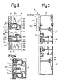
- the fixing elements with respect to the profiles 28 are fixed by means of profiled bars 34, 35 which have molded-on locking or clamping elements 34a, 35a, which are directed inwards, ie towards the respective connecting element 32, and which cooperate with counter elements on the horizontal profile 28.
- the profile bars 34 arranged on the inside of the cabin - on the left in FIG. 2 - have a substantially L-shaped cross section, but a first, bead-like thickening is provided on the outside of the edge defined by the two legs, while on the A second, bead-like thickening is provided on the inside of the short leg at the free end thereof, these two bead-like thickenings, in cooperation with counter-elements 28a of profile 28, serving as locking elements 34a.
- the counter elements of the profile 28 are formed by a web 28 d, which may be slightly undercut in its foot region, and by an undercut shoulder 28 b, which are located on opposite sides of a pocket 28 c, in which the short leg of the L-shaped profile bar 34 is latched or is clamped.
- the spring force required for the locking or jamming of the profile bars 34 is effected by acting on the long leg thereof, in the region of the free end of this leg, the short leg being somewhat deformed to produce the snap connection with the profile 28.
- the second outer webs 35c have a roughly approximately E-shaped cross section and have a base 35b from which three webs 35c project, which face the transverse profile 28 when the profile rods 35 are mounted.
- the inner ends of the Both outer webs 35c are designed as hook-shaped latching elements 35a, which engage behind hook-shaped projections 28 of the profile 28, the distance between the hook-shaped projections 28a being somewhat smaller than the distance between the latching elements 35a in the unloaded state.
- the third, innermost web 35c of each of the profiled bars 35 serves as a pressing element, which exerts a force directed toward the inside of the cabin on the adjacent filler element 32 or on the seal 44 surrounding the filler element 32.
- the horizontal edge regions of the infill elements 32 above and below a transverse web 28 are fixed by the profiled bars 34, 35 under spring tension such that they are either to the inside of the cabin or to the outside if necessary the same can be removed and repaired, changed or replaced in general.
- the horizontal profiles 24 along the upper and lower edges of each of the tabular components 12 and on the vertical profiles 26 on the right and left side of the profile frame corresponding profile strips be provided for releasable mounting of the Ausfachrii, as will be explained in more detail below for the vertically extending profiles 26 with reference to FIG. 3 of the drawing.
- an outer profile rod 35 and an inner profile rod 34 are provided only on the inside facing the Ausfachelement 32.
- the loosening of the E-shaped cross-section outer profile bars 35 takes place in the usual manner with such locking elements, for example by moving the blade of a screwdriver from the outside of the cabin between the outer locking element 28a of the profile 28 and the outer locking element 35a Introduces profile bar 35 and then the gap formed thereby expanded until the locking connection is released.
- the seals 44, 45 can be preformed seals, for example made of neoprene rubber, or can also be formed by a permanently elastic sealing compound used when inserting the relevant filler element 32.
- the lockable profile strips 34, 35 for interacting with the vertical profiles 26 of the profile frame are essentially the same as the profile strips 34, 35 for interacting with the horizontal profile 28. Furthermore, it is clear from FIG. 3 that Between the vertical profiles 26 of two adjacent profile frames in the area of a stationary, vertical support element 46, one of the vertical supports 18, an intermediate element or an intermediate support 50 is provided, which is screwed to the support element 46 by means of screws 52 and with which the frame elements or the profiles 26 are screwed together by means of screws 54, the axes of which are perpendicular to the axes of the screws 52.
- the screw heads of the screws 54 are accessible through openings in the profiles 26, which later, ie after the screw connection has been made, between the profile 26 and the intermediate support 50 are closed by means of cover plugs.
- the profiled bars 35 are essentially designed in the same way as in the exemplary embodiment according to FIG. 2.
- the profiled bars 34 which are arranged on the inside of the cabin according to FIG , A cross-sectionally F-shaped profile with two legs 34c, which can be locked under spring tension with associated, hook-shaped counter-elements 26a of the profile 26.
- FIG. 4 differs from that of FIG. 2 in that instead of the two separate L-shaped profile strips 34 for the detachable mounting of the upper and lower Ausfachelements 32, a single profile strip 34 is provided with two parts L-shaped in cross section is that running parallel to the inside of the profile 28 Cross bar 34c are interconnected. Furthermore, in the exemplary embodiment according to FIG. 4, the locking elements 34a are provided in the region of the free ends of the short legs of the L-shaped sections and can be locked with spring clips 36, which are fastened by means of screws 38, which are fitted into a molded screw groove 40 on the inside of the profile 28 are screwed in.
- the bead-like thickening on the edge defined by the outside of the two legs of the profile bar 34 is designed as a relatively pronounced latching element 34a for engaging behind a correspondingly designed counter-element on the undercut shoulder 28b, in an embodiment of the invention there is also Possibility of forming a profile bar 34 as an L-shaped profile without latching elements, the short leg in this case being reliably held in the associated pocket 28c of the profile 28 by the long leg of the profile 34 having been latched with the profile bar 35 opposite it the profile 28 is acted upon by the elastically deformable seals 44, 45 and the Ausfachelement 32 with an effective force on its inside, which in the 2 would result in a counterclockwise pivoting movement, but this is prevented by the short leg engaging in the pocket 28c, so that the opening angle between the short and the long leg opens somewhat with elastic deformation of the material of the profile bar is and thus a resilient clamping of the profile bar 34 takes place.
- a profile bar 34 on the inside of the cabin can be released by exerting an outward pressure on its long leg, thereby releasing the clamping force at the points of contact between the pocket 28c and the short leg and pulling off the profile bar 34 to the inside of the cabin is made possible.
Landscapes
- Engineering & Computer Science (AREA)
- Architecture (AREA)
- Civil Engineering (AREA)
- Structural Engineering (AREA)
- Body Structure For Vehicles (AREA)
- Working Measures On Existing Buildindgs (AREA)
Applications Claiming Priority (2)
| Application Number | Priority Date | Filing Date | Title |
|---|---|---|---|
| DE3623630 | 1986-07-12 | ||
| DE19863623630 DE3623630A1 (de) | 1986-07-12 | 1986-07-12 | Kabinenkonstruktion |
Publications (2)
| Publication Number | Publication Date |
|---|---|
| EP0253312A2 true EP0253312A2 (fr) | 1988-01-20 |
| EP0253312A3 EP0253312A3 (fr) | 1989-08-09 |
Family
ID=6305093
Family Applications (1)
| Application Number | Title | Priority Date | Filing Date |
|---|---|---|---|
| EP87109925A Withdrawn EP0253312A3 (fr) | 1986-07-12 | 1987-07-09 | Construction de cabine |
Country Status (2)
| Country | Link |
|---|---|
| EP (1) | EP0253312A3 (fr) |
| DE (1) | DE3623630A1 (fr) |
Cited By (3)
| Publication number | Priority date | Publication date | Assignee | Title |
|---|---|---|---|---|
| AU608719B2 (en) * | 1988-06-25 | 1991-04-11 | Taikisha, Ltd. | Method of installing painting system and paintingmachine control unit for use in painting booth |
| WO1992003627A1 (fr) * | 1990-08-15 | 1992-03-05 | John Clement Preston | Cloture pour site de construction |
| CN101522313B (zh) * | 2006-07-14 | 2013-01-09 | 杜尔系统有限责任公司 | 涂漆设备以及相应的操作方法 |
Families Citing this family (2)
| Publication number | Priority date | Publication date | Assignee | Title |
|---|---|---|---|---|
| DE4227889A1 (de) * | 1992-08-22 | 1994-02-24 | Goetz Metall Anlagen | Lackierkabine |
| DE19508234A1 (de) * | 1994-03-19 | 1995-09-21 | Rainer Horstmann | Haus zur Nutzung als Freizeithaus |
Citations (7)
| Publication number | Priority date | Publication date | Assignee | Title |
|---|---|---|---|---|
| US3487601A (en) * | 1966-12-22 | 1970-01-06 | Dexion Ltd | Support based,panel attachment |
| DE2336888A1 (de) * | 1972-07-20 | 1974-01-31 | Wandenbouw Twente B V | Stuetzelement mit zugehoeriger abdeckleiste fuer die befestigung von wandtafeln an trennwandelementen |
| AT368037B (de) * | 1981-01-12 | 1982-08-25 | Unitherm Oesterreich Gmbh | Spritzlackier- und trockenkabine |
| DE3149189A1 (de) * | 1981-12-11 | 1983-06-23 | Golde GmbH Spritzgußwerk, 8192 Geretsried | Fenster, insbesondere nach aussen zu oeffnendes fenster |
| FR2539336A1 (fr) * | 1983-01-14 | 1984-07-20 | Skm Sa | Cabine de peinture en panneaux modulaires |
| US4502410A (en) * | 1983-11-07 | 1985-03-05 | Haden Schweitzer Corporation | Enclosure for treatment tank |
| DE3510860A1 (de) * | 1985-03-26 | 1986-10-09 | Dürr GmbH, 7000 Stuttgart | Kabinenkonstruktion |
Family Cites Families (3)
| Publication number | Priority date | Publication date | Assignee | Title |
|---|---|---|---|---|
| US1229046A (en) * | 1915-12-06 | 1917-06-05 | Vilbiss Mfg Co De | Booth. |
| US2948362A (en) * | 1957-07-19 | 1960-08-09 | Herbert S Jones | Building structure |
| FR1294849A (fr) * | 1961-04-19 | 1962-06-01 | Compteurs Comp D | Dispositif de cloisonnement démontable |
-
1986
- 1986-07-12 DE DE19863623630 patent/DE3623630A1/de not_active Withdrawn
-
1987
- 1987-07-09 EP EP87109925A patent/EP0253312A3/fr not_active Withdrawn
Patent Citations (7)
| Publication number | Priority date | Publication date | Assignee | Title |
|---|---|---|---|---|
| US3487601A (en) * | 1966-12-22 | 1970-01-06 | Dexion Ltd | Support based,panel attachment |
| DE2336888A1 (de) * | 1972-07-20 | 1974-01-31 | Wandenbouw Twente B V | Stuetzelement mit zugehoeriger abdeckleiste fuer die befestigung von wandtafeln an trennwandelementen |
| AT368037B (de) * | 1981-01-12 | 1982-08-25 | Unitherm Oesterreich Gmbh | Spritzlackier- und trockenkabine |
| DE3149189A1 (de) * | 1981-12-11 | 1983-06-23 | Golde GmbH Spritzgußwerk, 8192 Geretsried | Fenster, insbesondere nach aussen zu oeffnendes fenster |
| FR2539336A1 (fr) * | 1983-01-14 | 1984-07-20 | Skm Sa | Cabine de peinture en panneaux modulaires |
| US4502410A (en) * | 1983-11-07 | 1985-03-05 | Haden Schweitzer Corporation | Enclosure for treatment tank |
| DE3510860A1 (de) * | 1985-03-26 | 1986-10-09 | Dürr GmbH, 7000 Stuttgart | Kabinenkonstruktion |
Cited By (4)
| Publication number | Priority date | Publication date | Assignee | Title |
|---|---|---|---|---|
| AU608719B2 (en) * | 1988-06-25 | 1991-04-11 | Taikisha, Ltd. | Method of installing painting system and paintingmachine control unit for use in painting booth |
| WO1992003627A1 (fr) * | 1990-08-15 | 1992-03-05 | John Clement Preston | Cloture pour site de construction |
| AU645345B2 (en) * | 1990-08-15 | 1994-01-13 | John Clement Preston | Hoardings for a construction site |
| CN101522313B (zh) * | 2006-07-14 | 2013-01-09 | 杜尔系统有限责任公司 | 涂漆设备以及相应的操作方法 |
Also Published As
| Publication number | Publication date |
|---|---|
| DE3623630A1 (de) | 1988-02-04 |
| EP0253312A3 (fr) | 1989-08-09 |
Similar Documents
| Publication | Publication Date | Title |
|---|---|---|
| EP0331690B1 (fr) | Revetement pour plafonds | |
| EP3556986B1 (fr) | Combinaison de profilés de guidage pour une fenêtre dotée d'un caisson de volet roulant pourvu de trappe de révision côté extérieur du bâtiment | |
| EP0718456A1 (fr) | Système de fermeture pour fenêtre, porte etc. | |
| DE2516160B2 (de) | Webeschaft mit am schaftstab verschiebbar und loesbar befestigbarem fuehrungsstueck | |
| DE3510860A1 (de) | Kabinenkonstruktion | |
| EP0355517A2 (fr) | Dispositif pour provoquer un écoulement laminaire | |
| DE3247691A1 (de) | Klotzbruecke oder gitterklotz zum festsetzen von glasscheiben od. dgl. in tuer- oder fensterrahmen | |
| EP0253312A2 (fr) | Construction de cabine | |
| DE19739644C2 (de) | Wand für die Kabine einer Lackieranlage | |
| DE3038862C2 (de) | Vorrichtung zum Aufbau von Schallschutzwänden | |
| EP0659953B1 (fr) | Dispositif de fixation pour revêtements muraux | |
| DE10013574A1 (de) | Vorrichtung und Verfahren zum lösbaren Befestigen einer Verkleidung an einer Wandung mit definierter Fuge | |
| DE3639894C2 (fr) | ||
| DE102014119021B4 (de) | Anordnung zum Befestigen eines Pfostens aus Kunststoff an einer Rahmenleiste eines Fensters oder einer Türe mittels eines Pfostenverbinders | |
| DE19719013C2 (de) | Mit einem Wandhalter versehenes, im Querschnitt U-förmiges Halteprofil für eine Trennwand | |
| DE4443232C1 (de) | Befestigungseinrichtung | |
| DE102017120676B4 (de) | Deckenverkleidungssystem | |
| DE3733359C2 (fr) | ||
| DE2329075B2 (de) | Unterdecke | |
| EP1873340A2 (fr) | Installation de porte | |
| DE102006016022B4 (de) | Vorrichtung zur drehbaren Halterung von zwei Flächenelementen und deren Verwendung | |
| DE202016107136U1 (de) | Basisprofil zur Aussteifung eines Aluminium-Kunststoff-Verbundblendrahmens und zur Verbindung mit einer Statikkonsole eines Rollladenkastens | |
| EP1096096B1 (fr) | Procédé de montage d'un élément de paroi | |
| EP0736436B1 (fr) | Véhicule ferroviaire | |
| EP0987396A2 (fr) | Habillage pour fenêtres ou portes |
Legal Events
| Date | Code | Title | Description |
|---|---|---|---|
| PUAI | Public reference made under article 153(3) epc to a published international application that has entered the european phase |
Free format text: ORIGINAL CODE: 0009012 |
|
| AK | Designated contracting states |
Kind code of ref document: A2 Designated state(s): DE ES GB IT SE |
|
| PUAL | Search report despatched |
Free format text: ORIGINAL CODE: 0009013 |
|
| RHK1 | Main classification (correction) |
Ipc: B05B 15/12 |
|
| AK | Designated contracting states |
Kind code of ref document: A3 Designated state(s): DE ES GB IT SE |
|
| STAA | Information on the status of an ep patent application or granted ep patent |
Free format text: STATUS: THE APPLICATION IS DEEMED TO BE WITHDRAWN |
|
| 18D | Application deemed to be withdrawn |
Effective date: 19900210 |
|
| RIN1 | Information on inventor provided before grant (corrected) |
Inventor name: ROECKLE, BERNHARD |