EP0253312A2 - Cabin construction - Google Patents
Cabin construction Download PDFInfo
- Publication number
- EP0253312A2 EP0253312A2 EP87109925A EP87109925A EP0253312A2 EP 0253312 A2 EP0253312 A2 EP 0253312A2 EP 87109925 A EP87109925 A EP 87109925A EP 87109925 A EP87109925 A EP 87109925A EP 0253312 A2 EP0253312 A2 EP 0253312A2
- Authority
- EP
- European Patent Office
- Prior art keywords
- cabin
- elements
- profile
- shaped
- construction according
- Prior art date
- Legal status (The legal status is an assumption and is not a legal conclusion. Google has not performed a legal analysis and makes no representation as to the accuracy of the status listed.)
- Withdrawn
Links
Images

Classifications
-
- E—FIXED CONSTRUCTIONS
- E04—BUILDING
- E04H—BUILDINGS OR LIKE STRUCTURES FOR PARTICULAR PURPOSES; SWIMMING OR SPLASH BATHS OR POOLS; MASTS; FENCING; TENTS OR CANOPIES, IN GENERAL
- E04H5/00—Buildings or groups of buildings for industrial or agricultural purposes
- E04H5/02—Buildings or groups of buildings for industrial purposes, e.g. for power-plants or factories
-
- B—PERFORMING OPERATIONS; TRANSPORTING
- B05—SPRAYING OR ATOMISING IN GENERAL; APPLYING FLUENT MATERIALS TO SURFACES, IN GENERAL
- B05B—SPRAYING APPARATUS; ATOMISING APPARATUS; NOZZLES
- B05B16/00—Spray booths
- B05B16/40—Construction elements specially adapted therefor, e.g. floors, walls or ceilings
Definitions
- the invention relates to a cabin construction for a production line, in particular a paint shop, with vertical support elements arranged in a grid spacing from one another and parallel to one another, in their installed position, with tabular components optionally provided with windows, doors and the like between the support elements and with connecting devices for connecting the support elements and the tabular components to form a continuous cabin wall between a cabin ceiling and a cabin floor.
- the side walls of the booth are formed by large-area panels which have a height of approximately 3.5 to 4 m and a grid width of 2 m, for example.
- These panels are made of painted sheet steel or stainless steel, with the edge of the steel plates being bent on all four sides, possibly several times, in order to obtain vertical (and horizontal) support elements, between which the remaining sheet metal material forms tabular components, in the necessary openings, such as lighting windows and observation windows.
- the individual panels are connected to one another in the region of their flanged longitudinal edges, which represent constructive vertical support elements, in particular screwed, in order to obtain a continuous cabin wall that extends from the cabin floor to the cabin ceiling, the cabin floor usually being formed by a grating that forms the Drainage of treatment and cleaning fluids allowed, while the cabin ceiling is formed by a filter mat construction, which in turn form the bottom part of the so-called plenum, in which fans and the like are arranged for removing the air extracted from the cabin.
- a disadvantage of this previously known cabin construction is that the individual panels are difficult to replace if, for example, a door or a closed wall surface is desired instead of a previously existing window.
- window and door openings are cut out, there is a comparatively large loss of material, which results in high manufacturing costs, especially when using stainless steel panels.
- each of the tabular components as an interchangeable unit, which extends from the cabin ceiling to the cabin floor, with a closed, rectangular profile frame which defines at least one compartment in which a plate-shaped Ausfachelement by means of holding devices from Inside the cabin is releasably fixable.
- This structural design has the advantage in cabin constructions that the profile frame is prefabricated as an identical assembly for all panel-shaped components and can be divided as required by transverse and / or longitudinal struts into the desired compartments, into which the plate-shaped Ausfachrii, in particular sheet metal plates and glass panes, but also door elements and the like can be used.
- the invention has for its object to provide an improved cabin construction, which on the one hand allows a quick and easy assembly of the cabin using fewer standard parts, which also a high flexibility for subsequent changes Lity offers and simplifies and speeds up maintenance, repair and retrofitting work, which ultimately also makes it possible to replace this component, even if access to a panel-shaped component on the inside of the cabin structure is difficult to replace.
- each of the tabular components is designed as an interchangeable unit which extends from the cabin ceiling to the cabin floor with a closed, rectangular profile frame which defines at least one compartment in which a plate-shaped Ausfachelement can be detachably fixed from one side of the cabin by means of mounting devices and that the mounting devices are designed so that the plate-shaped Ausfachelement can be detachably fixed by them from the other side of the cabin.
- the profile frame can be prefabricated as an identical assembly for all panel-shaped components and then divided as required by transverse and / or longitudinal struts into the desired compartments, into which the plate-shaped Ausfachieri, in particular sheet metal plates and glass panes, but also door elements and the like are used, the mounting devices being constructed in such a way that a panel-shaped component can be exchanged either from the inside or from the outside of the cabin, it being assumed that especially in the case of permanently installed devices on the inside the corresponding area on the outside of the cabin the cabin is usually kept clear so that the device can be monitored visually if necessary.
- this ensures in the vast majority of all cases that the tabular components used according to the invention, which form the actual wall elements of the cabin, are easily accessible either from the inside or from the outside.
- the closed, rectangular profile frame is a comparatively stable component that can be manufactured with very precise dimensions and maintains its shape without twisting or warping, so that there are no problems in this regard when replacing the entire panel-shaped component, and moreover already when the first assembly is carried out between stationary, vertical support elements, the required connections can be made quickly and precisely.
- the holding devices comprise rod-shaped fastening elements which can be detachably connected to the profile frame by means of latching devices.
- the locking of the rod-shaped fasteners with the frame not only has the advantage that the insertion and replacement of the Ausfachieri can be done quickly and easily, for example compared to the production of screw connections, but also has the further significant advantage that the Required locking elements on the rod-shaped fastening elements on the one hand and on the profile frame on the other hand, are covered for the latching outwards, ie towards the inside of the cabin, and not in their function can be impaired or rendered unusable by paint residues and the like, as would be the case, for example, with openly accessible screw heads inside the spray booth.
- the holding devices comprise profile bars which have molded-on locking elements which can be locked with counter-elements on profile elements of the profile frame, since the releasable fastening the infill elements in this construction are not only punctiform, as would be the case with mounting devices in the form of screws or the like, but in a linear area that can extend in particular over the entire width or height of a profile frame to be filled out.
- This type of releasable attachment of the tabular components ensures, especially when these components are glass panes, in conjunction with suitable sealing elements, a good sealing effect and, moreover, a distribution of the forces exerted by the mounting devices, so that the components are subjected to excessive stress , especially the glass panes, is avoided.
- the counter-elements as spring clips which are fastened to the profile elements of the profile frame, in particular by means of screws
- the profile elements of the profile frame preferably having an integrally formed screw groove for the fastening the spring clips serving screws are provided.
- the flanks of the screw groove are preferably provided with ribs running in the longitudinal direction and offset in height, which form a kind of prefabricated thread for the fastening screws.
- spring clips as counter elements offers the advantage that there are no special restrictions for the design of the profile elements of the profile frame, as may be observed when using aluminum profiles if the counter elements also break off from the other parts of the profile several replacements should be avoided.
- FIG. 1 shows a detail from a painting system with a cabin construction according to the invention, the cut edges facing the viewer in FIG. 1 not being hatched in deviation from the usual practice in order to increase clarity.
- the cabin walls 10 are composed of individual, tabular components 12, which extend from the cabin floor 14 to the cabin ceiling 16 and are fastened to firmly mounted, vertical supports 18.
- the cabin floor 14 is formed by a grid, under which the circulation and cleaning devices that are customary in spray booths are located, while the cabin ceiling 16 is formed by a filter mat arrangement, which in turn forms the floor of the so-called plenum 20.
- each of the tabular components 12 has a circumferential, closed, rectangular profile frame 24, 26 made of special profiles 24, 26 that run vertically or horizontally in the installed position.
- the profile frame is divided by transverse webs 28, which are also designed as special profiles, into individual compartments 30, each of which is filled with a plate-shaped filler element 32, the filler elements being specifically glass plates and metal plates, for example stainless steel plates or aluminum plates.
- the profiles 24, 26, 28 are preferably extruded aluminum hollow profiles, which have the advantage that they combine great rigidity with low weight and material consumption.
- the horizontal profiles 28 are provided with shoulders 29, which can form a support surface for the metal sheets, disks and the like serving as infill elements 32.
- the fixing elements with respect to the profiles 28 are fixed by means of profiled bars 34, 35 which have molded-on locking or clamping elements 34a, 35a, which are directed inwards, ie towards the respective connecting element 32, and which cooperate with counter elements on the horizontal profile 28.
- the profile bars 34 arranged on the inside of the cabin - on the left in FIG. 2 - have a substantially L-shaped cross section, but a first, bead-like thickening is provided on the outside of the edge defined by the two legs, while on the A second, bead-like thickening is provided on the inside of the short leg at the free end thereof, these two bead-like thickenings, in cooperation with counter-elements 28a of profile 28, serving as locking elements 34a.
- the counter elements of the profile 28 are formed by a web 28 d, which may be slightly undercut in its foot region, and by an undercut shoulder 28 b, which are located on opposite sides of a pocket 28 c, in which the short leg of the L-shaped profile bar 34 is latched or is clamped.
- the spring force required for the locking or jamming of the profile bars 34 is effected by acting on the long leg thereof, in the region of the free end of this leg, the short leg being somewhat deformed to produce the snap connection with the profile 28.
- the second outer webs 35c have a roughly approximately E-shaped cross section and have a base 35b from which three webs 35c project, which face the transverse profile 28 when the profile rods 35 are mounted.
- the inner ends of the Both outer webs 35c are designed as hook-shaped latching elements 35a, which engage behind hook-shaped projections 28 of the profile 28, the distance between the hook-shaped projections 28a being somewhat smaller than the distance between the latching elements 35a in the unloaded state.
- the third, innermost web 35c of each of the profiled bars 35 serves as a pressing element, which exerts a force directed toward the inside of the cabin on the adjacent filler element 32 or on the seal 44 surrounding the filler element 32.
- the horizontal edge regions of the infill elements 32 above and below a transverse web 28 are fixed by the profiled bars 34, 35 under spring tension such that they are either to the inside of the cabin or to the outside if necessary the same can be removed and repaired, changed or replaced in general.
- the horizontal profiles 24 along the upper and lower edges of each of the tabular components 12 and on the vertical profiles 26 on the right and left side of the profile frame corresponding profile strips be provided for releasable mounting of the Ausfachrii, as will be explained in more detail below for the vertically extending profiles 26 with reference to FIG. 3 of the drawing.
- an outer profile rod 35 and an inner profile rod 34 are provided only on the inside facing the Ausfachelement 32.
- the loosening of the E-shaped cross-section outer profile bars 35 takes place in the usual manner with such locking elements, for example by moving the blade of a screwdriver from the outside of the cabin between the outer locking element 28a of the profile 28 and the outer locking element 35a Introduces profile bar 35 and then the gap formed thereby expanded until the locking connection is released.
- the seals 44, 45 can be preformed seals, for example made of neoprene rubber, or can also be formed by a permanently elastic sealing compound used when inserting the relevant filler element 32.
- the lockable profile strips 34, 35 for interacting with the vertical profiles 26 of the profile frame are essentially the same as the profile strips 34, 35 for interacting with the horizontal profile 28. Furthermore, it is clear from FIG. 3 that Between the vertical profiles 26 of two adjacent profile frames in the area of a stationary, vertical support element 46, one of the vertical supports 18, an intermediate element or an intermediate support 50 is provided, which is screwed to the support element 46 by means of screws 52 and with which the frame elements or the profiles 26 are screwed together by means of screws 54, the axes of which are perpendicular to the axes of the screws 52.
- the screw heads of the screws 54 are accessible through openings in the profiles 26, which later, ie after the screw connection has been made, between the profile 26 and the intermediate support 50 are closed by means of cover plugs.
- the profiled bars 35 are essentially designed in the same way as in the exemplary embodiment according to FIG. 2.
- the profiled bars 34 which are arranged on the inside of the cabin according to FIG , A cross-sectionally F-shaped profile with two legs 34c, which can be locked under spring tension with associated, hook-shaped counter-elements 26a of the profile 26.
- FIG. 4 differs from that of FIG. 2 in that instead of the two separate L-shaped profile strips 34 for the detachable mounting of the upper and lower Ausfachelements 32, a single profile strip 34 is provided with two parts L-shaped in cross section is that running parallel to the inside of the profile 28 Cross bar 34c are interconnected. Furthermore, in the exemplary embodiment according to FIG. 4, the locking elements 34a are provided in the region of the free ends of the short legs of the L-shaped sections and can be locked with spring clips 36, which are fastened by means of screws 38, which are fitted into a molded screw groove 40 on the inside of the profile 28 are screwed in.
- the bead-like thickening on the edge defined by the outside of the two legs of the profile bar 34 is designed as a relatively pronounced latching element 34a for engaging behind a correspondingly designed counter-element on the undercut shoulder 28b, in an embodiment of the invention there is also Possibility of forming a profile bar 34 as an L-shaped profile without latching elements, the short leg in this case being reliably held in the associated pocket 28c of the profile 28 by the long leg of the profile 34 having been latched with the profile bar 35 opposite it the profile 28 is acted upon by the elastically deformable seals 44, 45 and the Ausfachelement 32 with an effective force on its inside, which in the 2 would result in a counterclockwise pivoting movement, but this is prevented by the short leg engaging in the pocket 28c, so that the opening angle between the short and the long leg opens somewhat with elastic deformation of the material of the profile bar is and thus a resilient clamping of the profile bar 34 takes place.
- a profile bar 34 on the inside of the cabin can be released by exerting an outward pressure on its long leg, thereby releasing the clamping force at the points of contact between the pocket 28c and the short leg and pulling off the profile bar 34 to the inside of the cabin is made possible.
Abstract
Description
Die Erfindung betrifft eine Kabinenkonstruktion für eine Fertigungsstraße, insbesondere eine Lackieranlage, mit in einem Rasterabstand voneinander und parallel zueinander angeordneten, in ihrer Einbaulage vertikalen Stützelementen,mit gegebenenfalls mit Fenstern, Türen und dergleichen versehenen tafelförmigen Bauelementen zwischen den Stützelementen und mit Verbindungseinrichtungen zum Verbinden der Stützelemente und der tafelförmigen Bauelemente zu einer durchgehenden Kabinenwand zwischen einer Kabinendecke und einem Kabinenboden.The invention relates to a cabin construction for a production line, in particular a paint shop, with vertical support elements arranged in a grid spacing from one another and parallel to one another, in their installed position, with tabular components optionally provided with windows, doors and the like between the support elements and with connecting devices for connecting the support elements and the tabular components to form a continuous cabin wall between a cabin ceiling and a cabin floor.
Bei üblichen Kabinenkonstruktionen von Lackieranlagen werden die Seitenwände der Kabine durch großflächige Panele gebildet, welche beispielsweise eine Höhe von etwa 3,5 bis 4 m und eine Rasterbreite von 2 m aufweisen. Diese Panele werden aus lackiertem Stahlblech oder aus Edelstahl hergestellt, wobei der Rand der Stahlplatten auf allen vier Seiten,gegebenenfalls mehrfach, umgebogen wird, um auf diese Weise vertikale (und horizontale) Stützelemente zu erhalten, zwischen denen das restliche Blechmaterial tafelförmige Bauelemente bildet, in die die erforderlichen Öffnungen, wie z.B. Beleuchtungsfenster und Beobachungsfenster, eingeschnitten werden. Die einzelnen Panele werden im Bereich ihrer umgebördelten Längskanten, welche konstruktiv vertikale Stützelemente darstellen, miteinander verbunden, insbesondere verschraubt, um so eine durchgehende Kabinenwand zu erhalten, die vom Kabinenboden bis zur Kabinendecke reicht, wobei der Kabinenboden üblicherweise durch einen Gitterrost gebildet wird, der das Abfließen von Behandlungs- und Reinigungsflüssigkeiten gestattet, während die Kabinendecke durch eine Filtermattenkonstruktion gebildet wird, die ihrerseits den Bodenteil des sogenannten Plenums bilden, in dem Ventilatoren und dergleichen zum Abführen der aus der Kabine abgesaugten Luft angeordnet sind.In conventional booth constructions of painting systems, the side walls of the booth are formed by large-area panels which have a height of approximately 3.5 to 4 m and a grid width of 2 m, for example. These panels are made of painted sheet steel or stainless steel, with the edge of the steel plates being bent on all four sides, possibly several times, in order to obtain vertical (and horizontal) support elements, between which the remaining sheet metal material forms tabular components, in the necessary openings, such as lighting windows and observation windows. The individual panels are connected to one another in the region of their flanged longitudinal edges, which represent constructive vertical support elements, in particular screwed, in order to obtain a continuous cabin wall that extends from the cabin floor to the cabin ceiling, the cabin floor usually being formed by a grating that forms the Drainage of treatment and cleaning fluids allowed, while the cabin ceiling is formed by a filter mat construction, which in turn form the bottom part of the so-called plenum, in which fans and the like are arranged for removing the air extracted from the cabin.
Nachteilig an dieser vorbekannten Kabinenkonstruktion ist es, daß sich die einzelnen Panele nur schwer auswechseln lassen, wenn beispielsweise anstelle eines zuvor vorhandenen Fensters eine Türe oder eine geschlossene Wandfläche gewünscht wird. Außerdem ergeben sich beim Ausschneiden von Fenster- und Türöffnungen vergleichsweise große Materialverluste, was speziell bei der Verwendung von Edelstahl-Panelen entsprechend hohe Fertigungskosten mitsichbringt. Dabei ist zu berücksichtigen, daß der Trend zu einer Vollverglasung im Hinblick auf den zunehmend größeren Einsatz von Fertigungsautomaten (Robotern) zunimmt, da diese Automaten bei ihrer Arbeit von der Außenseite der Kabine her möglichst genau beobachtet werden sollen, so daß der Materialverlust durchdas Ausschneiden von Fensterflächen bei den bekannten Kabinenkonstruktionen zunehmend stärker ins Gewicht fällt und auch statische Probleme mit sich bringt.A disadvantage of this previously known cabin construction is that the individual panels are difficult to replace if, for example, a door or a closed wall surface is desired instead of a previously existing window. In addition, when window and door openings are cut out, there is a comparatively large loss of material, which results in high manufacturing costs, especially when using stainless steel panels. It should be borne in mind that the trend towards full glazing is increasing with regard to the increasing use of production machines (robots), since these machines work from the outside of the cabin should be observed as closely as possible, so that the loss of material due to the cutting out of window areas in the known cabin constructions becomes increasingly important and also brings with it static problems.
Es wurde auch bereits vorgeschlagen, zwischen den einzelnen Panelen separate, vertikale Stützelemente anzuordnen, insbesondere Vierkantrohre, wodurchdas Auswechseln der einzelnen Panele vereinfacht wird und gegebenenfalls mit geringeren Materialstärken für die Panele gearbeitet werden kann, da diese durch die Stützelemente in ihrer Funktion als tragende Bauteile entlastet werden. Das Problem der beträchtlichen Materialabfälle durch das Ausschneiden von Fensteröffnungen und dergleichen wird jedoch auch durch diese Konstruktion nicht überwunden. Außerdem bleibt auch das Problem erhalten, daß die Panele nach wie vor nur von der Außenseite der Kabine her ausgewechselt werden können, da die umgebördelten Randbereiche der Panele zur Erzielung glatter Innenwandflächen in der Kabine bei den bekannten Kabinenkonstruktionen stets auf der Außenseite der Kabine angeordnet werden. Da jedoch auf der Außenseite der Kabinenwände Versorgungsleitungen, Steuerschränke und dergleichen angeordnet sind, ist das Auswechseln von Bauteilen von der Außenseite der Kabine her häufig sehr problematisch, wenn nicht unmöglich, so daß die bekannten Kabinenkonstruktionen letztlich für jede Fertigungsstraße von vornherein "maßgeschneidert" angefertigt werden müssen und spätere Änderungen kaum möglich sind.It has also already been proposed to arrange separate, vertical support elements, in particular square tubes, between the individual panels, which simplifies the replacement of the individual panels and, if necessary, can be worked with lower material thicknesses for the panels, since the support elements relieve them of their function as load-bearing components will. However, this construction does not overcome the problem of considerable waste of material due to the cutting out of window openings and the like. In addition, the problem remains that the panels can still only be replaced from the outside of the cabin, since the flanged edge areas of the panels are always arranged on the outside of the cabin in order to achieve smooth interior wall surfaces in the cabin in the known cabin designs. However, since supply lines, control cabinets and the like are arranged on the outside of the cabin walls, the replacement of components from the outside of the cabin is often very problematic, if not impossible, so that the known cabin constructions are ultimately “tailor-made” for each production line have to and later changes are hardly possible.
Ein weiterer Nachteil der vorbekannten Kabinenkonstruktion besteht schließlich darin, daß die Glasscheiben der Beleuchtungsfenster und der Beobachtungsfenster im allgemeinen mittels eines Gummiköders dichtend in die Blechpanele eingesetzt sind, was Brandschutzprobleme mit sich bringt, da die Gummi- bzw. Kunststoffdichtungen bei einem Brand im Inneren der Kabine schnell Feuer fangen, so daß die eingesetzten Scheiben herausfallen.Another disadvantage of the previously known cabin construction is that the glass panes of the lighting windows and the observation windows are generally inserted into the sheet metal panels in a sealing manner by means of a rubber bait, which causes fire protection problems, since the rubber or plastic seals in the event of a fire inside the cabin catch fire quickly so that the inserted panes fall out.
Aus der DE-A-23 36 888 ist es für die Befestigung von Wandtafeln an Trennwandlementen bereits bekannt, Stützelemente zu verwenden, die an einem Pfosten oder dergleichen befestigt werden und den Rand einer benachbarten Wandtafel mit hakenförmigen Ansätzen erfassen und mit denen eine Abdeckleiste verrastbar ist. Diese Konstruktion ist jedoch nicht speziell für den Aufbau von Kabinen, insbesondere von Lackieranlagen, bestimmt und insofern umständlich, als zum Entfernen einer Wandtafel zunächst die Abdeckleiste und dann das Stützelement selbst vollständig entfernt werden müssen, wobei dennoch nur ein Herausnehmen auf einer Seite der Konstruktion möglich ist. Zusätzlich sind besondere Gegenelemente erforderlich, an welche sich die Wandtafeln mit ihrer gegenüberliegenden Seite anlegen können.From DE-A-23 36 888 it is already known for the attachment of wall panels to partition elements to use support elements which are attached to a post or the like and which grip the edge of an adjacent wall panel with hook-shaped approaches and with which a cover strip can be locked . However, this construction is not specifically designed for the construction of cabins, in particular paint shops, and is cumbersome in that, in order to remove a wall panel, the cover strip and then the support element itself must first be completely removed, although only removal on one side of the construction is possible is. In addition, special counter elements are required, on which the wall panels can rest with their opposite side.
Aus der US-A-3 487 601 ist ferner eine Konstruktion zur Halterung von Panelen bekannt, bei der an den Stützpfosten besondere Anschlagelemente angebracht oder angeformt werden müssen, die einerseits der Abstützung der einen Seite einer Wandtafel und andererseits der Festlegung von Halteelementen dienen, die sich an der gegenüberliegenden Seite der Wandtafeln abstützen. Auch bei dieser Konstruktion können Wandtafeln nur von einer Seite her ausgewechselt werden.From US-A-3 487 601 a construction for mounting panels is also known, in which special stop elements have to be attached or formed on the support posts, which serve on the one hand to support one side of a blackboard and on the other hand to define holding elements which support yourself on the opposite side of the blackboards. Even with this construction panels can only be replaced from one side.
Gemäß einem früheren Vorschlag besteht ferner die Möglichkeit, bei einer Kabinenkonstruktion jedes der tafelförmigen Bauelemente als auswechselbare, von der Kabinendecke bis zum Kabinenboden reichende Baueinheit mit einem geschlossenen, rechteckigen Profilrahmen auszubilden, welcher mindestens ein Fach definiert, in dem ein plattenförmiges Ausfachelement mittels Halterungseinrichtungen von der Innenseite der Kabine her lösbar festlegbar ist. Diese konstruktive Ausgestaltung bietet bei Kabinenkonstruktionen den Vorteil, daß der Profilrahmen als für alle tafelförmigen Bauelemente identische Baugruppe vorgefertigt und nach Bedarf durch Quer- und/oder Längsstreben in die gewünschten Fächer unterteilt werden kann, in die dann die plattenförmigen Ausfachelemente, insbesondere Blechplatten und Glasscheiben, aber auch Türelemente und dergleichen, eingesetzt werden. Andererseits ist gemäß dem früheren Vorschlag nur von der Innenseite der Kabine her ein Auswechseln der Ausfachelemente möglich. Es hat sich jedoch gezeigt, daß das Auswechseln von Ausfachelementen auch durch im Inneren der Kabinenkonstruktion befindliche Einrichtungen, insbesondere wenn es sich dabei um fest montierte Vorrichtungen, wie zum Beispiel Roboter handelt, erheblich befindert oder unmöglich gemacht werden kann.According to an earlier proposal, there is also the possibility, in the case of a cabin construction, of designing each of the tabular components as an interchangeable unit, which extends from the cabin ceiling to the cabin floor, with a closed, rectangular profile frame which defines at least one compartment in which a plate-shaped Ausfachelement by means of holding devices from Inside the cabin is releasably fixable. This structural design has the advantage in cabin constructions that the profile frame is prefabricated as an identical assembly for all panel-shaped components and can be divided as required by transverse and / or longitudinal struts into the desired compartments, into which the plate-shaped Ausfachelemente, in particular sheet metal plates and glass panes, but also door elements and the like can be used. On the other hand, according to the previous proposal, it is only possible to replace the infill elements from the inside of the cabin. However, it has been shown that the replacement of infill elements can also be considerably located or made impossible by means of devices located inside the cabin structure, in particular if these are fixed devices, such as robots.
Ausgehend vom Stand der Technik und der vorstehend aufgezeigten Problematik, liegt der Erfindung die Aufgabe zugrunde, eine verbesserte Kabinenkonstruktion anzugeben, welche einerseits eine schnelle und einfache Montage der Kabine unter Verwendung weniger Normteile gestattet, welche ferner für nachträgliche Änderungen eine hohe Flexibi lität bietet und Wartungs-, Reparatur- und Umrüstarbeiten vereinfacht und beschleunigt und welche schließlich auch bei einem erschwerten Zugang zu einem auszuwechselnden, tafelförmigen Bauelement auf der Innenseite der Kabinenkonstruktion eine Auswechselung dieses Bauelements ermög licht.Based on the prior art and the problems outlined above, the invention has for its object to provide an improved cabin construction, which on the one hand allows a quick and easy assembly of the cabin using fewer standard parts, which also a high flexibility for subsequent changes Lity offers and simplifies and speeds up maintenance, repair and retrofitting work, which ultimately also makes it possible to replace this component, even if access to a panel-shaped component on the inside of the cabin structure is difficult to replace.
Diese Aufgabe wird bei einer Kabinenkonstruktion der eingangs angegebenen Art gemäß der Erfindung dadurch gelöst, daß jedes der tafelförmigen Bauelemente als auswechselbare, von der Kabinendecke bis zum Kabinenboden reichende Baueinheit mit einem geschlossenen, rechteckigen Profilrahmen ausgebildet ist, welcher mindestens ein Fach definiert, in dem ein plattenförmiges Ausfachelement mittels Halterungseinrichtungen von der einen Seite der Kabine her lösbar festlegbar ist und daß die Halterungseinrichtungen so ausgebildet sind, daß das plattenförmige Ausfachelement durch sie auch von der anderen Seite der Kabine her lösbar festlegbar ist.This object is achieved in a cabin construction of the type specified at the outset in accordance with the invention in that each of the tabular components is designed as an interchangeable unit which extends from the cabin ceiling to the cabin floor with a closed, rectangular profile frame which defines at least one compartment in which a plate-shaped Ausfachelement can be detachably fixed from one side of the cabin by means of mounting devices and that the mounting devices are designed so that the plate-shaped Ausfachelement can be detachably fixed by them from the other side of the cabin.
Es ist ein besonderer Vorteil der Kabinenkonstruktion gemäß der Erfindung, daß der Profilrahmen als für alle tafelförmigen Bauelemente identische Baugruppe vorgefertigt und dann nach Bedarf durch Quer- und/oder Längsstreben in die gewünschten Fächer unterteilt werden kann, in die dann die plattenförmigen Ausfachelemente, insbesondere Blechplatten und Glasscheiben, aber auch Türelemente und dergleichen eingesetzt werden, wobei die Halterungseinrichtungen so konstruiert sind, daß ein tafelförmiges Bauelement entweder von innen her oder von der Außenseite der Kabine her ausgewechselt werden kann, wobei davon ausgegangen wird, daß speziell bei fest installierten Vorrichtungen im Inneren der Kabine der entsprechende Bereich auf der Außenseite der Kabine üblicherweise freigehalten wird, um das Arbeiten der Vorrichtung gegebenenfalls visuell überwachen zu können. Damit ist aber in der ganz überwiegenden Anzahl aller Fälle gewährleistet, daß die gemäß der Erfindung verwendeten, tafelförmigen Bauelemente, welche die eigentlichen Wandelemente der Kabine bilden, entweder von innen oder von außen gut zugänglich sind.It is a particular advantage of the cabin construction according to the invention that the profile frame can be prefabricated as an identical assembly for all panel-shaped components and then divided as required by transverse and / or longitudinal struts into the desired compartments, into which the plate-shaped Ausfachelemente, in particular sheet metal plates and glass panes, but also door elements and the like are used, the mounting devices being constructed in such a way that a panel-shaped component can be exchanged either from the inside or from the outside of the cabin, it being assumed that especially in the case of permanently installed devices on the inside the corresponding area on the outside of the cabin the cabin is usually kept clear so that the device can be monitored visually if necessary. However, this ensures in the vast majority of all cases that the tabular components used according to the invention, which form the actual wall elements of the cabin, are easily accessible either from the inside or from the outside.
Weiterhin ist der geschlossene, rechteckige Profilrahmen ein vergleichsweise stabiles Bauteil, welches mit sehr genauen Abmessungen gefertigt werden kann und seine Form beibehält, ohne sich zu verwinden oder zu verziehen, so daß sich diesbezüglich bei einem Auswechweln des gesamten tafelförmigen Bauelements keine Probleme ergeben und außerdem bereits bei der ersten Montage zwischen ortsfest montierten, vertikalen Stützelementen eine schnelle und exakte Herstellung der erforderlichen Verbindungen ermöglicht wird.Furthermore, the closed, rectangular profile frame is a comparatively stable component that can be manufactured with very precise dimensions and maintains its shape without twisting or warping, so that there are no problems in this regard when replacing the entire panel-shaped component, and moreover already when the first assembly is carried out between stationary, vertical support elements, the required connections can be made quickly and precisely.
Darüberhinaus sind unnötige Materialverluste auf ein Minimum reduziert, da als Ausfachelemente rechteckige Blech- und Glastafeln passend mit geringen Zuschnittverlusten zugeschnitten werden können, wenn das tafeloder bahnförmige Ausgangsmaterial in seiner Breite von vornherein auf die Rasterbreite der lichten Weite des Profilrahmens abgestimmt wird.In addition, unnecessary material losses are reduced to a minimum, since rectangular sheet metal and glass panels can be cut to size with a minimum of cut losses if the width of the panel or sheet-shaped starting material is matched from the outset to the grid width of the clear width of the profile frame.
Schließlich kann durch eine geeignete Ausbildung der Profile der Elemente des Profilrahmens das Einsetzen der Ausfachelemente in die Fächer des Rahmens erleichtert und deren anschließende Festlegung mittels Halterungseinrichtungen vereinfacht werden.Finally, by means of a suitable design of the profiles of the elements of the profile frame, the insertion of the infill elements into the compartments of the frame can be facilitated and their subsequent fixing can be simplified by means of mounting devices.
In Ausgestaltung der Erfindung hat es sich als vorteilhaft erwiesen, wenn die Halterungseinrichtungen stabförmige Befestigungselemente umfassen, welche mittels Rasteinrichtungen lösbar mit dem Profilrahmen verbindbar sind. Das Verrasten der stabförmigen Befestigungselemente mit dem Rahmen hat dabei nicht nur den Vorteil, daß das Einsetzen und Auswechseln der Ausfachelemente schnell und einfach vorgenommen werden kann, beispielsweise im Vergleich zur Herstellung von Schraubverbindungen, sondern bringt auch den weiteren, wesentlichen Vorteil mit sich, daß die für das Verrasten erforderlichen Rastelemente an den stabförmigen Befestigungselementen einerseits und am Profilrahmen andererseits nach außen, d.h. zur Innenseite der Kabine hin, abgedeckt sind und in ihrer Funktion nicht durch Farbrückstände und dergleichen beeinträchtigt bzw. unbrauchbar gemacht werden können, wie dies beispielsweise bei offen zugänglichen Schraubenköpfen im Inneren der Spritzkabine der Fall wäre.In an embodiment of the invention, it has proven to be advantageous if the holding devices comprise rod-shaped fastening elements which can be detachably connected to the profile frame by means of latching devices. The locking of the rod-shaped fasteners with the frame not only has the advantage that the insertion and replacement of the Ausfachelemente can be done quickly and easily, for example compared to the production of screw connections, but also has the further significant advantage that the Required locking elements on the rod-shaped fastening elements on the one hand and on the profile frame on the other hand, are covered for the latching outwards, ie towards the inside of the cabin, and not in their function can be impaired or rendered unusable by paint residues and the like, as would be the case, for example, with openly accessible screw heads inside the spray booth.
Was die konstruktive Ausgestaltung der Rastelemente anbelangt, so bieten sich diesbezüglich mehrere vorteilhafte Möglichkeiten. Einerseits besteht die Möglichkeit, an einem der miteinander zu verrastenden Bauteile einen Federclip, beispielsweise aus Stahl, anzuschrauben oder auf andere Weise zu befestigen und am anderen Bauelement eine Aussparung zur Aufnahme der freien Enden des Federclips und zum Verrasten desselben mit vorspringenden Nasen des anderen Bauteils vorzusehen. Weiterhin besteht die Möglichkeit, an beiden Bauteilen hinterschnittene Rastelemente anzuformen, welche unter Ausnutzung der natürlichen Elastizität des Materials des Rahmens und/oder der stabförmigen Befestigungselemente die Herstellung einer lösbaren Rastverbindung gestatten. Dabei ist zu berücksichtigen, daß die angeformten Rastelemente nur für eine geringe Anzahl von Auswechselvorgängen ausgebildet sein müssen, so daß sie unter Umständen auch aus einem leicht ermüdbaren Material, wie z.B. stranggegossenem bzw. -gepresstem Aluminium bestehen können.As far as the structural design of the locking elements is concerned, there are several advantageous possibilities in this regard. On the one hand, there is the possibility of screwing a spring clip, for example made of steel, onto one of the components to be locked together, or of attaching it in some other way, and of providing a recess on the other component for receiving the free ends of the spring clip and for locking the same with projecting lugs of the other component . Furthermore, there is the possibility of forming undercut locking elements on both components, which allow the use of the natural elasticity of the material of the frame and / or the rod-shaped fastening elements to produce a releasable locking connection. It should be taken into account that the molded locking elements need only be designed for a small number of replacement processes, so that they can also be made of an easily fatigued material, such as e.g. extruded or pressed aluminum.
In Ausgestaltung der Erfindung hat es sich als vorteilhaft erwiesen, wenn die Halterungseinrichtungen Profilstäbe umfassen, welche angeformte Rastelemente aufweisen, die mit Gegenelementen an Profilelementen des Profilrahmens verrastbar sind, da das lösbare Befestigen der Ausfachelemente bei dieser konstruktiven Ausgestaltung nicht nur punktförmig erfolgt, wie dies bei Halterungseinrichtungen in Form von Schrauben oder dergleichen der Fall wäre, sondern in einem linienförmigen Bereich, der sich insbesondere über die gesamte Breite oder Höhe eines auszufachenden Profilrahmens erstrecken kann. Diese Art der lösbaren Befestigung der tafelförmigen Bauelemente gewährleistet, insbesondere, wenn es sich bei diesen Bauelementen um Glasscheiben handelt, in Verbindung mit geeigneten Dichtungselementen eine gute Dichtwirkung und im übrigen auch eine Verteilung der von den Halterungseinrichtungen ausgeübten Kräfte, so daß eine punktuelle Überbeanspruchung der Bauelemente, insbesondere der Glasscheiben, vermieden wird.In an embodiment of the invention, it has proven to be advantageous if the holding devices comprise profile bars which have molded-on locking elements which can be locked with counter-elements on profile elements of the profile frame, since the releasable fastening the infill elements in this construction are not only punctiform, as would be the case with mounting devices in the form of screws or the like, but in a linear area that can extend in particular over the entire width or height of a profile frame to be filled out. This type of releasable attachment of the tabular components ensures, especially when these components are glass panes, in conjunction with suitable sealing elements, a good sealing effect and, moreover, a distribution of the forces exerted by the mounting devices, so that the components are subjected to excessive stress , especially the glass panes, is avoided.
Bei der Verwendung von Halterungseinrichtungen mit Profilstäben ergibt sich eine besonders einfache Konstruktion mit wenigen Bauteilen, wenn Gegenelemente an den Profilelementen des Profilrahmens einstückig angeformte, zu den Rastelementen der Profilstäbe komplementäre Rastelemente sind.The use of mounting devices with profile bars results in a particularly simple construction with few components if counter-elements are integrally molded on the profile elements of the profile frame and are complementary to the locking elements of the profile bars.
In Ausgestaltung der Erfindung besteht aber auch die Möglichkeit, die Gegenelemente als Federclips auszubilden, welche an den Profilelementen des Profilrahmens, insbesondere mittels Schrauben, befestigt sind, wobei die Profilelemente des Profilrahmens vorzugsweise mit einer angeformten Schraubennut für die der Befestigung der Federclips dienenden Schrauben versehen sind. Dabei werden die Flanken der Schraubennut vorzugsweise mit in Längsrichtung verlaufenden,in der Höhe gegeneinander versetzten Rippen versehen, welche für die Befestigungsschrauben eine Art vorgefertigtes Gewinde bilden.In an embodiment of the invention, however, there is also the possibility of designing the counter-elements as spring clips which are fastened to the profile elements of the profile frame, in particular by means of screws, the profile elements of the profile frame preferably having an integrally formed screw groove for the fastening the spring clips serving screws are provided. The flanks of the screw groove are preferably provided with ribs running in the longitudinal direction and offset in height, which form a kind of prefabricated thread for the fastening screws.
Die Verwendung von Federclips als Gegenelemente bietet dabei den Vorteil, daß sich für die Ausgestaltung der Profilelemente des Profilrahmens keine besonderen Einschränkungen ergeben, wie sie gegebenenfalls bei der Verwendung von Aluminiumprofilen zu beachten sind, wenn ein Abbrechen der Gegenelemente von den ibrigen Teilen des Profils auch nach mehreren Auswechselvorgängen sicher vermieden werden soll.The use of spring clips as counter elements offers the advantage that there are no special restrictions for the design of the profile elements of the profile frame, as may be observed when using aluminum profiles if the counter elements also break off from the other parts of the profile several replacements should be avoided.
Weitere Einzelheiten und Vorteile der Erfindung werden nachstehend anhand von Zeichnungen noch näher erläutert. Es zeigen:
- Fig. 1 eine schematische, perspektivische Querschnittsdarstellung einer Lackieranlage mit einer Kabinenkonstruktion gemäß der Erfindung;
- Fig. 2 einen senkrechten Teil-Längsschnitt durch eine Kabinenwand einer erfindungsgemäßen Kabinenkonstruktion, gesehen in Richtung des Pfeils A in Fig. 1;
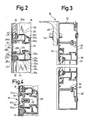
- Fig. 3 einen Teil-Querschnitt durch eine Kabinenwand einer erfindungsgemäßen Kabinenkonstruktion gemäß Fig. 1 längs der Linie 3-3 in dieser Figur; und
- Fig. 4 einen der Darstellung gemäß Fig. 2 entsprechenden Teil-Längsschnitt für eine abgewandelte Ausführungsform einer Kabinenkonstruktion gemäß der Erfindung.
- Figure 1 is a schematic, perspective cross-sectional view of a painting system with a cabin construction according to the invention.
- 2 shows a vertical partial longitudinal section through a cabin wall of a cabin construction according to the invention, seen in the direction of arrow A in FIG. 1;
- 3 shows a partial cross section through a cabin wall of a cabin construction according to the invention according to FIG. 1 along the line 3-3 in this figure; and
- 4 shows a partial longitudinal section corresponding to the illustration according to FIG. 2 for a modified embodiment of a cabin construction according to the invention.
Im einzelnen zeigt Fig. 1 einen Ausschnitt aus einer Lackieranlage mit einer erfindungsgemäßen Kabinenkonstruktion, wobei die in Fig. 1 dem Betrachter zugewandten Schnittkanten abweichend von der üblichen Praxis zur Erhöhung der Übersichtlichkeit nicht schraffiert sind.1 shows a detail from a painting system with a cabin construction according to the invention, the cut edges facing the viewer in FIG. 1 not being hatched in deviation from the usual practice in order to increase clarity.
Man erkennt, daß die Kabinenwände 10 aus einzelnen, tafelförmigen Bauelementen 12 zusammengesetzt sind, die sich vom Kabinenboden 14 bis zur Kabinendecke 16 erstrecken und an fest montierten, vertikalen Stützen 18 befestigt sind. Dabei wird der Kabinenboden 14 durch ein Gitter gebildet, unter dem sich die bei Spritzkabinen üblichen Umwälz- und Reinigungseinrichtungen befinden, während die Kabinendecke 16 durch eine Filtermattenanordnung gebildet wird, die ihrerseits den Boden des sogenannten Plenums 20 bildet.It can be seen that the
Wie aus Fig. 1 in Verbindung mit Fig. 2 und 3 deutlich wird, besitzt jedes der tafelförmigen Bauelemente 12 einen umlaufenden, geschlossenen, rechteckigen Profilrahmen 24,26 aus in der Einbaulage vertikal bzw. horizontal verlaufenden Spezialprofilen 24,26.As is clear from FIG. 1 in conjunction with FIGS. 2 and 3, each of the
Beim Ausführungsbeispiel ist der Profilrahmen durch Querstege 28, die ebenfalls als Spezialprofile ausgebildet sind, in einzelne Fächer 30 unterteilt, die jeweils mit einem plattenförmigen Ausfachelement 32 ausgefacht sind, wobei die Ausfachelemente speziell Glasplatten und Metallplatten, beispielsweise Edelstahlplatten oder Aluminiumplatten sind. Die Profile 24,26,28 sind vorzugsweise durch Strangpressen hergestellte Aluminium-Hohlprofile, welche den Vorteil haben, daß sie eine große Steifigkeit mit einem geringen Gewicht und Materialverbrauch vereinigen.In the exemplary embodiment, the profile frame is divided by
Wie Fig. 2 zeigt, sind die horizontalen Profile 28 mit Schultern 29 versehen, welche eine Auflagefläche für die als Ausfachelemente 32 dienenden Blechtafeln, Scheiben und dergleichen bilden können. Das Festlegen der Ausfachelemente bezüglich der Profile 28 erfolgt dabei mittels Profilstäben 34,35, welche angeformte, nach innen, d.h. gegen das jeweilige Ausfachelement 32, gerichtete Rast- bzw. Klemmelemente 34a, 35a besitzen, die mit Gegenelementen an dem horizontalen Profil 28 zusammenwirken.As shown in FIG. 2, the
Im einzelnen haben die auf der Innenseite der Kabine - in Fig. 2 links - angeordneten Profilstäbe 34 einen im wesentlichen L-förmigen Querschnitt, wobei jedoch an der Außenseite der durch die beiden Schenkel definierten Kante eine erste,wulstartige Verdickung vorgesehen ist, während auf der Innenseite des kurzen Schenkels am freien Ende desselben eine zweite, wulstartige Verdickung vorgesehen ist, wobei diese beiden wulstartigen Verdickungen im Zusammenwirken mit Gegenelementen 28a des Profils 28 als Rastelemente 34a dienen. Beim Ausführungsbeispiel werden die Gegenelemente des Profils 28 durch einen in seinem Fußbereich gegebenenfalls etwas hinterschnittenen Steg 28 d und durch eine hinterschnittene Schulter 28b gebildet, die sich auf gegenüberliegenden Seiten einer Tasche 28c befinden, in der der kurze Schenkel des L-förmigen Profilstabs 34 verrastet bzw. festgeklemmt ist. Die erforderliche Federkraft für das Verrasten bzw. Verklemmen der Profilstäbe 34 wird dabei durch Einwirken auf den langen Schenkel derselben, und zwar im Bereich des freien Endes dieses Schenkels, wobei der kurze Schenkel zur Herstellung der Rastverbindung mit dem Profil 28 etwas verformt wird.Specifically, the
Die Profilstäbe 35 haben beim Ausführungsbeispiel gemäß Fig. 2 einen in grober Annäherung etwa E-förmigen Querschnitt und besitzen eine Basis 35b, von der drei Stege 35c abstehen, die bei montierten Profilstäben 35 dem Querprofil 28 zugewandt sind. Die inneren Enden der beiden äußeren Stege 35c sind als hakenförmige Rastelemente 35a ausgebildet, welche hakenförmige Vorsprünge 28 ades Profils 28 hintergreifen, wobei der Abstand zwischen den hakenförmigen Vorsprüngen 28a etwas kleiner ist als der Abstand zwischen den Rastelementen 35a im unbelasteten Zustand. Auf diese Weise ergibt sich beim Verrasten der Profilstäbe 35 mit dem Profil 28 eine Federvorspannung zwischen den beiden, mit den Rastelementen 35a versehenen Stegen 35c, so daß diese lösbar an dem Profil 28 festgelegt sind. Der dritte, am weitesten innen liegende Steg 35c jedes der Profilstäbe 35 dient als Anpresselement, welches auf das angrenzende Ausfachelement 32 bzw. auf die das Ausfachelement 32 umgebende Dichtung 44 eine zur Innenseite der Kabine gerichtete Kraft ausübt.2 have a roughly approximately E-shaped cross section and have a base 35b from which three
Wie aus der vorstehenden Beschreibung der Ausführungsform gemäß Fig. 2 deutlich wird, werden die horizontalen Randbereiche der Ausfachelemente 32 oberhalb und unterhalb eines Querstegs 28 durch die Profilstäbe 34, 35 unter Federvorspannung derart festgelegt, daß sie im Bedarfsfalle entweder zur Innenseite der Kabine oder zur Außenseite derselben herausgenommen werden und repariert, geändert bzw. ganz allgemein ausgewechselt werden können. Dabei versteht es sich, daß an den horizontalen Profilen 24 längs des oberen und des unteren Randes jedes der tafelförmigen Bauelemente 12 und an den vertikalen Profilen 26 auf der rechten bzw. linken Seite des Profilrahmens entsprechende Profilleisten zur lösbaren Halterung der Ausfachelemente vorgesehen werden, wie dies nachstehend für die vertikal verlaufenden Profile 26 anhand der Fig. 3 der Zeichnung noch näher erläutert werden wird. Weiterhin versteht es sich, daß bei den den umlaufenden Profilrahmen 22 bildenden Profilen 24,26 jeweils nur auf der dem Ausfachelement 32 zugewandten Innenseite jeweils ein äußerer Profilstab 35 und ein innerer Profilstab 34 vorgesehen sind.As is clear from the above description of the embodiment according to FIG. 2, the horizontal edge regions of the
Im einzelnen erfolgt das Lösen der einen E-förmigen Querschnitt aufweisenden äußeren Profilstäbe 35 in der bei derartigen Rastelementen üblichen Weise, beispielsweise indem man die Klinge eines Schraubendrehers von der Außenseite der Kabine her zwischen das äußere Rastelement 28a des Profils 28 und das äußere Rastelement 35a des Profilstabs 35 einführt und dann den dabei gebildeten Spalt bis zum Lösen der Rastverbindung erweitert.In particular, the loosening of the E-shaped cross-section outer profile bars 35 takes place in the usual manner with such locking elements, for example by moving the blade of a screwdriver from the outside of the cabin between the
Bei den auf der Innenseite der Kabine angeordneten Profilstäben 34 mit ihrem im wesentlichen L-förmigen Profil ist es dagegen im allgemeinen ausreichend, wenn auf das freie Ende des langen Schenkels beispielsweise von Hand ein ausreichender Druck ausgeübt wird, um die Dichtung 44 auf der Außenseite des Ausfachelements und gegebenenfalls eine weitere Dichtung 45 auf der Innenseite desselben derart elastisch zu verformen, daß das Rastelement 34a an der Außenseite der durch die Schenkel des Profilstabs 34 definierten Kante von der als Gegenelement dienenden, hinterschnittenen Schulter 28b gelöst wird, wobei gegebenenfalls auch eine gewisse elastische Verformung der Stege 35c des gegenüberliegenden Profilstabs 35 erfolgen kann. In diesem Zusammenhang ist zu beachten, daß die Dichtungen 44,45 vorgeformte Dichtungen, beispielsweise aus Neopren-Gummi, sein können oder auch durch eine beim Einsetzen des betreffenden Ausfachelements 32 verwendete, dauerelastische Dichtungsmasse gebildet werden können.In contrast, in the case of the profile bars 34 arranged on the inside of the cabin with their substantially L-shaped profile, it is generally sufficient if sufficient pressure is exerted on the free end of the long leg, for example by hand, to seal the
Wie Fig. 3 zeigt, sind die verrastbaren Profilleisten 34,35 für das Zusammenwirken mit den vertikalen Profilen 26 des Profilrahmens im wesentlichen ebenso ausgebildet wie die Profilleisten 34,35 zum Zusammenwirken mit dem horizontalen Profil 28. Ferner wird aus Fig. 3 deutlich, daß zwischen den senkrechten Profilen 26 zweier benachbarter Profilrahmen im Bereich eines ortsfest montierten, vertikalen Stützelements 46 einer der vertikalen Stützen 18 ein Zwischenelement bzw. eine Zwischenstütze 50 vorgesehen ist, welche mit Hilfe von Schrauben 52 mit dem Stützelement 46 verschraubt ist und mit welcher die Rahmenelemente bzw. die Profile 26 mittels Schrauben 54 verschraubt sind, deren Achsen senkrecht zu den Achsen der Schrauben 52 verlaufen. Die Schraubenköpfe der Schrauben 54 sind dabei durch Öffnungen der Profile 26 zugänglich, welche später, d.h. nach der Herstellung der Schraubverbindung, zwischen dem Profil 26 und der Zwischenstütze 50 mittels Abdeckstopfen verschlossen werden.As shown in FIG. 3, the lockable profile strips 34, 35 for interacting with the
Bei dem Ausführungsbeispiel gemäß Fig. 3 sind die Profilstäbe 35 im wesentlichen ebenso ausgebildet wie bei dem Ausführungsbeispiel gemäß Fig. 2. Abweichend von dem Ausführungsbeispiel gemäß Fig. 2 haben jedoch die Profilstäbe 34, welche gemäß Fig. 3 auf der Innenseite der Kabine angeordnet sind, ein im Querschnitt F-förmiges Profil mit zwei Schenkeln 34c, welche mit zugeordneten, hakenförmigen Gegenelementen 26a des Profils 26 unter Federvorspannung verrastbar sind.In the exemplary embodiment according to FIG. 3, the profiled bars 35 are essentially designed in the same way as in the exemplary embodiment according to FIG. 2. In contrast to the exemplary embodiment according to FIG. 2, however, the profiled bars 34 which are arranged on the inside of the cabin according to FIG , A cross-sectionally F-shaped profile with two
Man erkennt, daß bei der konstruktiven Ausgestaltung gemäß Fig. 3 ebenfalls ein Auswechseln der Ausfachelemente 32 von der Innenseite und von der Außenseite der Kabine her möglich ist. Außerdem wird wie bei der Konstruktion gemäß Fig. 2 auf der Innenseite der Kabine - in Fig. 3 links - eine durchgehende, im wesentlichen glatte Fläche erhalten, welche eine leichte Innenreinigung der Kabine gewährleistet.It can be seen that in the structural configuration according to FIG. 3 it is also possible to replace the
Das Ausführungsbeispiel gemäß Fig. 4 unterscheidet sich von demjenigen gemäß Fig. 2 dadurch, daß anstelle der zwei getrennten L-förmigen Profilleisten 34 für die lösbare Halterung des oberen und des unteren Ausfachelements 32 eine einzige Profilleiste 34 mit zwei im Querschnitt L-förmigen Teilen vorgesehen ist, die über einen parallel zur Innenseite des Profils 28 verlaufenden Quersteg 34c miteinander verbunden sind. Ferner sind bei dem Ausführungsbeispiel gemäß Fig. 4 die Rastelemente 34a im Bereich der freien Enden der kurzen Schenkel der L-förmigen Teilstücke vorgesehen und mit Federclips 36 verrastbar, welche mittels Schrauben 38 befestigt sind, die in eine angeformte Schraubennut 40 auf der Innenseite des Profils 28 eingeschraubt sind. Dabei ist es vorteilhaft, in die Flanken der Schraubennut mit in Längsrichtung verlaufenden, in der Höhe gegeneinander versetzten Rippen versehen sind, welche eine Art vorgefertigtes Innengewinde für die Schrauben 38 bilden. Die Clips 36 liegen dabei vollständig zwischen den Ausfachelementen 32, so daß sie beim Auswechseln derselben nicht demontiert werden müssen.The embodiment of FIG. 4 differs from that of FIG. 2 in that instead of the two separate L-shaped profile strips 34 for the detachable mounting of the upper and
Während bei dem Ausführungsbeispiel gemäß Fig. 2 die wulstartige Verdickung an der durch die Außenseite der beiden Schenkel des Profilstabs 34 definierten Kante als relativ ausgeprägtes Rastelement 34a zum Hintergreifen eines entsprechend ausgebildeten Gegenelements an der hinterschnittenen Schulter 28b ausgebildet ist, besteht in Ausgestaltung der Erfindung ferner die Möglichkeit, einen Profilstab 34 als L-förmiges Profil ohne Rastelemente auszubilden, wobei der kurze Schenkel in diesem Fall in der zugeordneten Tasche 28c des Profils 28 dadurch zuverlässig gehalten wird, daß der lange Schenkel des Profils 34 nach dem Verrasten des ihm gegeniberliegenden Profilstabs 35 mit dem Profil 28 über die elastisch verformbaren Dichtungen 44, 45 und das Ausfachelement 32 mit einer auf seine Innenseite wirksamen Kraft beaufschlagt wird, die bei dem Ausführungsbeispiel gemäß Fig. 2 eine Schwenkbewegung im Gegenuhrzeigersinn zur Folge haben würde, die jedoch dadurch verhindert wird, daß der kurze Schenkel in die Tasche 28c eingreift, so daß der Öffnungswinkel zwischen dem kurzen und dem langen Schenkel unter elastischer Verformung des Materials des Profilstabes etwas geöffnet wird und damit ein federelastisches Festklemmen des Profilstabs 34 erfolgt. Auch bei dieser Ausgestaltung lässt sich ein Profilstab 34 auf der Innenseite der Kabine dadurch lösen, daß ein nach außen gerichteter Druck auf seinen langen Schenkel ausgeübt wird, wodurch die Klemmkraft an den Berührungspunkten zwischen der Tasche 28c und dem kurzen Schenkel aufgehoben und ein Abziehen des Profilstabs 34 zur Innenseite der Kabine ermöglicht wird.2, the bead-like thickening on the edge defined by the outside of the two legs of the
Aus der vorstehenden Beschreibung wird deutlich, daß mit der erfindungsgemäßen Kabinenkonstruktion einerseits eine sehr hohe Flexibilität beim Aufbau und Umbau von Spritzkabinen und dergleichen erreicht werden kann, und zwar durch Auswechseln von Ausfachelementen von innen oder von außen, während andererseits eine weitgehend ebene Kabineninnenwand erhalten wird, die sich leicht reinigen lässt und an der keine Befestigungselemente vorhanden sind, die durch Farbstoffreste und dergleichen unbrauchbar oder schwer betätigbar werden könnten. Dabei haben lediglich die ortsfest montierten vertikalen Stützelemente und gegebenenfalls die Zwischenstützen eine tragende Funktion, während die tafelförmigen Bauelemente gewissermaßen eine "innere Fassade" der Kabinenwand bilden und keine tragende Funktion haben. Daher besteht auch die Möglichkeit, zwischen der Kabinendecke 16 und dem oberen horizontalen Profil der einzelnen Profilrahmen einen kleinen Spalt freizulassen, welcher den Einbau und das Auswechseln der tafelförmigen Bauelemente erleichtert und durch einen vertikalen Schenkel einer Winkelschiene an der Unterseite der Kabinendecke 16 verschlossen werden kann, wie dies in Fig. 1 angedeutet ist. Zusätzlich oder stattdessen könnte zwischen den obersten horizontalen Elementen der Profilrahmen und der Kabinendecke gegebenenfalls auch eine elastomere Dichtung angebracht werden.From the above description it is clear that on the one hand a very high degree of flexibility in the construction and conversion of spray booths and the like can be achieved with the cabin construction according to the invention, namely by exchanging infill elements from the inside or from the outside, while on the other hand a largely flat cabin inner wall is obtained, which is easy to clean and on which there are no fastening elements which could become unusable or difficult to operate due to dye residues and the like. Only the fixed vertical support elements and possibly the intermediate supports have a load-bearing function during the tabular components form a kind of "inner facade" of the cabin wall and have no supporting function. Therefore, there is also the possibility of leaving a small gap between the
Claims (7)
Applications Claiming Priority (2)
| Application Number | Priority Date | Filing Date | Title |
|---|---|---|---|
| DE19863623630 DE3623630A1 (en) | 1986-07-12 | 1986-07-12 | CABIN DESIGN |
| DE3623630 | 1986-07-12 |
Publications (2)
| Publication Number | Publication Date |
|---|---|
| EP0253312A2 true EP0253312A2 (en) | 1988-01-20 |
| EP0253312A3 EP0253312A3 (en) | 1989-08-09 |
Family
ID=6305093
Family Applications (1)
| Application Number | Title | Priority Date | Filing Date |
|---|---|---|---|
| EP87109925A Withdrawn EP0253312A3 (en) | 1986-07-12 | 1987-07-09 | Cabin construction |
Country Status (2)
| Country | Link |
|---|---|
| EP (1) | EP0253312A3 (en) |
| DE (1) | DE3623630A1 (en) |
Cited By (3)
| Publication number | Priority date | Publication date | Assignee | Title |
|---|---|---|---|---|
| AU608719B2 (en) * | 1988-06-25 | 1991-04-11 | Taikisha, Ltd. | Method of installing painting system and paintingmachine control unit for use in painting booth |
| WO1992003627A1 (en) * | 1990-08-15 | 1992-03-05 | John Clement Preston | Hoardings for a construction site |
| CN101522313B (en) * | 2006-07-14 | 2013-01-09 | 杜尔系统有限责任公司 | Paint shop and corresponding method of operation |
Families Citing this family (2)
| Publication number | Priority date | Publication date | Assignee | Title |
|---|---|---|---|---|
| DE4227889A1 (en) * | 1992-08-22 | 1994-02-24 | Goetz Metall Anlagen | Paint booth |
| DE19508234A1 (en) * | 1994-03-19 | 1995-09-21 | Rainer Horstmann | Structure for collapsible house |
Citations (7)
| Publication number | Priority date | Publication date | Assignee | Title |
|---|---|---|---|---|
| US3487601A (en) * | 1966-12-22 | 1970-01-06 | Dexion Ltd | Support based,panel attachment |
| DE2336888A1 (en) * | 1972-07-20 | 1974-01-31 | Wandenbouw Twente B V | SUPPORT ELEMENT WITH ASSOCIATED COVERING STRIP FOR FASTENING WALL PANELS TO PARTITION WALL ELEMENTS |
| AT368037B (en) * | 1981-01-12 | 1982-08-25 | Unitherm Oesterreich Gmbh | SPRAY PAINT AND DRY CABIN |
| DE3149189A1 (en) * | 1981-12-11 | 1983-06-23 | Golde GmbH Spritzgußwerk, 8192 Geretsried | Window, in particular window to be opened outwards |
| FR2539336A1 (en) * | 1983-01-14 | 1984-07-20 | Skm Sa | Painting booth made from modular panels |
| US4502410A (en) * | 1983-11-07 | 1985-03-05 | Haden Schweitzer Corporation | Enclosure for treatment tank |
| DE3510860A1 (en) * | 1985-03-26 | 1986-10-09 | Dürr GmbH, 7000 Stuttgart | Booth structure |
Family Cites Families (3)
| Publication number | Priority date | Publication date | Assignee | Title |
|---|---|---|---|---|
| US1229046A (en) * | 1915-12-06 | 1917-06-05 | Vilbiss Mfg Co De | Booth. |
| US2948362A (en) * | 1957-07-19 | 1960-08-09 | Herbert S Jones | Building structure |
| FR1294849A (en) * | 1961-04-19 | 1962-06-01 | Compteurs Comp D | Removable partitioning device |
-
1986
- 1986-07-12 DE DE19863623630 patent/DE3623630A1/en not_active Withdrawn
-
1987
- 1987-07-09 EP EP87109925A patent/EP0253312A3/en not_active Withdrawn
Patent Citations (7)
| Publication number | Priority date | Publication date | Assignee | Title |
|---|---|---|---|---|
| US3487601A (en) * | 1966-12-22 | 1970-01-06 | Dexion Ltd | Support based,panel attachment |
| DE2336888A1 (en) * | 1972-07-20 | 1974-01-31 | Wandenbouw Twente B V | SUPPORT ELEMENT WITH ASSOCIATED COVERING STRIP FOR FASTENING WALL PANELS TO PARTITION WALL ELEMENTS |
| AT368037B (en) * | 1981-01-12 | 1982-08-25 | Unitherm Oesterreich Gmbh | SPRAY PAINT AND DRY CABIN |
| DE3149189A1 (en) * | 1981-12-11 | 1983-06-23 | Golde GmbH Spritzgußwerk, 8192 Geretsried | Window, in particular window to be opened outwards |
| FR2539336A1 (en) * | 1983-01-14 | 1984-07-20 | Skm Sa | Painting booth made from modular panels |
| US4502410A (en) * | 1983-11-07 | 1985-03-05 | Haden Schweitzer Corporation | Enclosure for treatment tank |
| DE3510860A1 (en) * | 1985-03-26 | 1986-10-09 | Dürr GmbH, 7000 Stuttgart | Booth structure |
Cited By (4)
| Publication number | Priority date | Publication date | Assignee | Title |
|---|---|---|---|---|
| AU608719B2 (en) * | 1988-06-25 | 1991-04-11 | Taikisha, Ltd. | Method of installing painting system and paintingmachine control unit for use in painting booth |
| WO1992003627A1 (en) * | 1990-08-15 | 1992-03-05 | John Clement Preston | Hoardings for a construction site |
| AU645345B2 (en) * | 1990-08-15 | 1994-01-13 | John Clement Preston | Hoardings for a construction site |
| CN101522313B (en) * | 2006-07-14 | 2013-01-09 | 杜尔系统有限责任公司 | Paint shop and corresponding method of operation |
Also Published As
| Publication number | Publication date |
|---|---|
| DE3623630A1 (en) | 1988-02-04 |
| EP0253312A3 (en) | 1989-08-09 |
Similar Documents
| Publication | Publication Date | Title |
|---|---|---|
| EP0331690B1 (en) | Ceiling facing | |
| EP3556986B1 (en) | Guide profile combination for a window with a roller blind box with revision flap on outside of building | |
| EP0718456A1 (en) | Closing device for window, door and the like | |
| DE2516160B2 (en) | WEB SHAFT WITH SLIDING AND DETACHABLE GUIDE PIECE ON THE SHAFT | |
| DE3510860A1 (en) | Booth structure | |
| EP0253312A2 (en) | Cabin construction | |
| DE19739644C2 (en) | Wall for the cabin of a paint shop | |
| DE3038862C2 (en) | Device for the construction of soundproof walls | |
| EP0659953B1 (en) | Device for fastening wall coverings | |
| DE10013574A1 (en) | Demountable fitting of wall panels and trim panels with strip bracket fixed to wall and panels held on strip by ratchet grips | |
| DE3639894C2 (en) | ||
| DE102014119021B4 (en) | Arrangement for attaching a post made of plastic to a frame strip of a window or a door by means of a post connector | |
| DE19719013C2 (en) | With a wall bracket, cross-sectionally U-shaped holding profile for a partition | |
| DE4443232C1 (en) | Fastening device | |
| DE102017120676B4 (en) | Ceiling cladding system | |
| DE3733359C2 (en) | ||
| DE2329075B2 (en) | False ceiling | |
| DE102006016022B4 (en) | Device for rotatably supporting two surface elements and their use | |
| DE202016107136U1 (en) | Base profile for stiffening an aluminum-plastic composite frame and for connection to a static console of a roller shutter box | |
| EP1096096B1 (en) | Method of mounting a wall element | |
| DE8421156U1 (en) | Detachable container | |
| EP0736436B1 (en) | Railway vehicle | |
| DE2802696A1 (en) | Air conditioning structural members - include two longitudinals forming back and top, designed for attaching front and end panels | |
| EP0987396A2 (en) | Cladding for windows or doors | |
| WO1990002237A1 (en) | Window or door leaf |
Legal Events
| Date | Code | Title | Description |
|---|---|---|---|
| PUAI | Public reference made under article 153(3) epc to a published international application that has entered the european phase |
Free format text: ORIGINAL CODE: 0009012 |
|
| AK | Designated contracting states |
Kind code of ref document: A2 Designated state(s): DE ES GB IT SE |
|
| PUAL | Search report despatched |
Free format text: ORIGINAL CODE: 0009013 |
|
| RHK1 | Main classification (correction) |
Ipc: B05B 15/12 |
|
| AK | Designated contracting states |
Kind code of ref document: A3 Designated state(s): DE ES GB IT SE |
|
| STAA | Information on the status of an ep patent application or granted ep patent |
Free format text: STATUS: THE APPLICATION IS DEEMED TO BE WITHDRAWN |
|
| 18D | Application deemed to be withdrawn |
Effective date: 19900210 |
|
| RIN1 | Information on inventor provided before grant (corrected) |
Inventor name: ROECKLE, BERNHARD |