EP3556986B1 - Guide profile combination for a window with a roller blind box with revision flap on outside of building - Google Patents
Guide profile combination for a window with a roller blind box with revision flap on outside of building Download PDFInfo
- Publication number
- EP3556986B1 EP3556986B1 EP19169107.0A EP19169107A EP3556986B1 EP 3556986 B1 EP3556986 B1 EP 3556986B1 EP 19169107 A EP19169107 A EP 19169107A EP 3556986 B1 EP3556986 B1 EP 3556986B1
- Authority
- EP
- European Patent Office
- Prior art keywords
- profile
- guide rail
- additional
- combination
- guide
- Prior art date
- Legal status (The legal status is an assumption and is not a legal conclusion. Google has not performed a legal analysis and makes no representation as to the accuracy of the status listed.)
- Active
Links
Images




Classifications
-
- E—FIXED CONSTRUCTIONS
- E06—DOORS, WINDOWS, SHUTTERS, OR ROLLER BLINDS IN GENERAL; LADDERS
- E06B—FIXED OR MOVABLE CLOSURES FOR OPENINGS IN BUILDINGS, VEHICLES, FENCES OR LIKE ENCLOSURES IN GENERAL, e.g. DOORS, WINDOWS, BLINDS, GATES
- E06B9/00—Screening or protective devices for wall or similar openings, with or without operating or securing mechanisms; Closures of similar construction
- E06B9/56—Operating, guiding or securing devices or arrangements for roll-type closures; Spring drums; Tape drums; Counterweighting arrangements therefor
- E06B9/58—Guiding devices
-
- E—FIXED CONSTRUCTIONS
- E06—DOORS, WINDOWS, SHUTTERS, OR ROLLER BLINDS IN GENERAL; LADDERS
- E06B—FIXED OR MOVABLE CLOSURES FOR OPENINGS IN BUILDINGS, VEHICLES, FENCES OR LIKE ENCLOSURES IN GENERAL, e.g. DOORS, WINDOWS, BLINDS, GATES
- E06B9/00—Screening or protective devices for wall or similar openings, with or without operating or securing mechanisms; Closures of similar construction
- E06B9/52—Devices affording protection against insects, e.g. fly screens; Mesh windows for other purposes
- E06B9/54—Roller fly screens
Definitions
- the invention relates to a guide profile combination for a window with a roller shutter box with an inspection hatch on the outside of the building, with the features of the preamble of claim 1.
- a guide profile combination is, for example DE19946405 A1 or DE202004012397 U1 known.
- roller shutter guides must be used to increase the distance from the curtain to the frame and, if necessary, to enable inspection from the outside, e.g. to replace a motor.
- roller shutter guides are designed in two parts, consisting of a structural profile and the actual roller shutter guide placed on it. The construction profile is attached to the frame and, if necessary, additionally connected to the building. The roller shutter guide can be removed at any time in the event of an overhaul.
- the disadvantages are, on the one hand, of a visual nature, because the division into the structure profile and roller shutter guide is always visible.
- the problem described occurs not only on the side boundaries of the wall opening, but also on every center post of a window that carries a roller shutter guide rail.
- the object of the present invention is therefore to provide a system for the case of the window with a roller shutter box with an external inspection panel that can be adapted to different types of window profile systems with as few individual parts as possible and thereby offers a uniform external view of the elements placed on the window from the outside.
- a solution to this task is provided by a leadership profile combination with the features of claim 1.
- the opening can be bridged by a web in the construction profile, which can subsequently be broken away or folded away.
- the existing hollow chamber can improve thermal insulation.
- the metallic guide rail profile according to a first embodiment of the profile combination has an extension in the form of a long side leg which extends from the guide rail to the attachment level on the frame and thus covers the entire side of the construction profile, including the second guide rail recess therein.
- Retrofitting insect protection is easy without having to replace the mounting profile.
- a different type of guide rail profile preferably made of aluminum, is used, which contains the guide rail for the main curtain and which is supplemented by an additional guide rail profile that adjoins the side without any gaps.
- the additional guide rail profile can be inserted with a U-shaped profile area, which forms an additional rail, into the guide rail recess that is already integrated in the attachment profile. If this is closed, a cover bar in front of the recess is first removed.
- the guide rail profile can be formed in one piece with the insert element, or separate parts can be provided which adjoin one another. In any case, lateral extensions should be molded onto one or both elements so that the side visible surfaces of the plastic construction profile next to the second guide rail are completely covered even when the insect protection profile is used.
- a construction profile 110 is shown according to the invention, which forms an essential element for a profile combination and which can be attached to the frame on the two outer sides of a window.
- the cross section is essentially L-shaped and is divided into a long and narrow profile section 114, which is intended to cover a wall reveal surface, and into a profile section intended to rest on a frame, which has an integrated additional guide rail recess 111 for an optional second curtain.
- the last-mentioned profile section has an extruded elastomeric seal 113 on its underside 117 facing the frame. On the top there is a groove 112 for receiving fastening screws and profile webs 115 for clip-receiving another profile.
- the guide rail recess 111 is covered by a profile web 116. This has a tapering wall thickness on each of the two side flanks of the additional guide rail recess 111, so that it can be broken out in order to open the additional guide rail recess 111. In the opening area, the width of the groove expands slightly and/or an undercut 118 is provided. Both serve to later attach an additional profile that can be inserted into the guide rail recess 111.
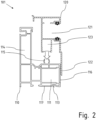
- FIG. 2 A first embodiment of a guide profile combination 101 according to the invention is shown in Figure 2 shown, namely before attaching a metallic guide rail profile 120 to the PVC extruded construction profile 110.
- the guide rail profile 120 forms a guide rail 121, on the side flanks of which additional guide profiles or brush seals are drawn in in order to prevent a roller shutter guided in the guide rail 121 from rattling .
- a groove 123 serves to accommodate the profile webs 115 of the structural profile 110, so that a locking connection with the structural profile 110 can be established by pushing the guide rail profile 120 onto the profile webs 115.
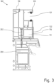
- the guide profile combination 101 fully mounted on a frame 200 shows Figure 3 .
- An additional shell 201 made of aluminum is placed on the frame 200.
- the construction profile 110 is placed on the attachment shell 201 and screwed to the frame 200 via several screws 202 arranged over the length of the profile.
- the profile leg 122 rests with its outer edge on the aluminum facing shell 201 and covers the entire lateral flank of the body profile 110. This means that the visible side is completely covered. If the profile section 114 of the structural profile 110 is plastered or clinkered, only the guide rail profile 120 made of aluminum remains visible in the external view of the guide profile combination 101.
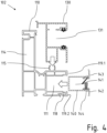
- a modified guide profile combination 102 can be used, which is in Figure 4 shown before assembly.
- the construction profile 110 is originally identical to that in the guide profile combination 101 according to Figures 1 to 3 is used.
- a different guide rail profile 130 is used in the guide profile combination 102.
- the guide rail 131 and the groove 133 for producing the locking connection is the same. Only the long profile leg to cover the side visible surface of the body profile 110 is missing.
- the profile web 116 (see Figure 1 ), which previously covered the integrated guide rail recess 111, is subsequently removed.
- an additional guide rail profile 140 can be inserted from the side as a third element of the profile combination 102.
- This has a U-shaped profile area which is inserted into the guide rail recess 111 and forms the second guide rail 141 for the insect protection curtain.
- Sharp-edged webs 144 are formed on the outer flanks of the U-shaped profile area, which engage in the walls of the guide rail recess 111 in the area of the undercuts 118 and thereby anchor the additional guide rail profile 140 therein.
- the U-shaped profile area is adjoined on both sides by extensions 142, 143, which cover the remaining strip-shaped visible surfaces 199.1, 119.2 next to the guide rail recess 111.
- the extension 143 creates a seamless connection to the guide rail profile 130.
- Figure 5 again shows the profile combination 102 screwed to the frame 200.
- the construction profile 110 is still placed on the attachment shell 201 and connected via screws 202. Only profiles 130 and 140 have been added. This means that two guide rails 131, 141 are available, which can be used to guide a roller shutter and an insect protection curtain.
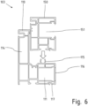
- a metallic guide rail profile can also be dispensed with. Instead there is a similar one to the guide rail profile 130 molded plastic guide rail profile 150 for use, as in Figure 6 shown. It can be used in the same way as the metallic guide rail profiles 120, 130 (cf. Fig. 2 , 4 ) can be snapped onto the profile webs 115 of the unchanged structural profile 110.
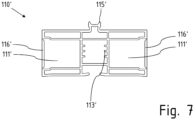
- FIG. 7 shows a construction profile 110', which is intended for attachment to a center post 200'.
- the construction profile 110' therefore has two integrated additional guide rail recesses 111' for an optional second curtain.
- Both integrated additional guide rail recesses 111' are each covered by a profile web 116' in the profile combination 101'.
- This has a tapering wall thickness on each of the two lateral flanks of the respective additional guide rail recess 111', so that it can be broken out in order to open the additional guide rail recess 111'.
- the width of the groove widens slightly and/or an undercut is provided to enable attachment of an additional profile that can be inserted into the guide rail recess 111'.
- Profile webs 115' projecting outwards are formed in the middle. They also serve as a locking connection with a guide rail profile 120' as well as for guiding fastening screws.
- webs 113 ' are formed on the interior to form screw channels.
- Figure 8 shows the assembly situation of a guide profile combination 101', which includes the assembly profile 110' and a first variant of a guide rail profile 120'.
- a center post 200' of a window is designed as a plastic hollow profile and, for optical reasons, has a cladding in the form of an attachment shell 201' made of aluminum.
- the construction profile 110' is placed on the attachment shell 201' and screwed to the center post 200' using fastening screws 202'.
- a profile leg 122' adjoins the profile area on both sides, which forms the guide rail 121'.
- the profile legs 122' each rest with their outer edge on the aluminum attachment shell 201' and each cover one side Flank of the body profile 110'. This means that the two side visible sides of the profile combination 101 'as well as a front visible side are completely formed by the aluminum guide rail profile 120', so that a uniform visual appearance results.
- a different type of guide rail profile 130' is used. It is the same in the upper profile area as the in Figure 7 shown guide rail profile 120 ', in particular the guide rails 131 ' and a groove on the underside for producing the locking connection with the structural profile 110 ' are the same. Only the long profile legs to cover the side visible surfaces of the body profile 110' are missing.
- the structural profile 110' There is a change to the structural profile 110': the two profile webs 116' (see Figure 7 ), which previously covered the additional guide rail recesses 111' that were integrated from the start, were subsequently removed.
- the additional guide rail profiles 140A', 140B' are designed in mirror images, so that the guide profile combination 102' comprises a total of at least four different profiles in addition to the assembly profile 110' and the guide rail profile 103'.
- each additional guide rail recess 111' there are on the additional guide rail profiles 140A', 140B' on both sides of a U-shaped profile area, which is inserted into the guide rail recess 111', Extensions 142', 143' molded.
- the extensions 143' create a seamless connection to the guide rail profile 130'; the extensions 142' connect to the attachment shell 201'.
- the additional guide rail profiles 140A', 140B are connected to the structure profile 110' via fastening screws 203'.
Landscapes
- Engineering & Computer Science (AREA)
- Structural Engineering (AREA)
- Architecture (AREA)
- Civil Engineering (AREA)
- Life Sciences & Earth Sciences (AREA)
- Insects & Arthropods (AREA)
- Pest Control & Pesticides (AREA)
- Operating, Guiding And Securing Of Roll- Type Closing Members (AREA)
Description
Die Erfindung betrifft eine Führungsprofilkombination für ein Fenster mit einem Rollladenkasten mit gebäudeaußenseitiger Revisionsklappe, mit den Merkmalen des Oberbegriffs des Anspruchs 1. Eine solche Führungsprofilkombination ist z.B. aus
Werden Rollladenkästen mit einer außenliegenden Revisionsöffnung verwendet, so sind hierfür spezielle Rollladenführungen einzusetzen, um den Abstand vom Behang zum Blendrahmen zu vergrößern und im Bedarfsfall eine Revision von außen zu ermöglichen, z.B. zum Austausch eines Motors. Allgemein üblich sind derartige Rollladenführungen zweiteilig ausgeführt, bestehend aus einem Aufbauprofil und der darauf aufgesetzten eigentlichen Rollladenführung. Das Aufbauprofil wird auf dem Blendrahmen befestigt und ggf. zusätzlich mit dem Baukörper verbunden. Die Rollladenführung bleibt für den Fall einer Revision jederzeit demontierbar.If roller shutter boxes with an external inspection opening are used, special roller shutter guides must be used to increase the distance from the curtain to the frame and, if necessary, to enable inspection from the outside, e.g. to replace a motor. Generally, such roller shutter guides are designed in two parts, consisting of a structural profile and the actual roller shutter guide placed on it. The construction profile is attached to the frame and, if necessary, additionally connected to the building. The roller shutter guide can be removed at any time in the event of an overhaul.
Die Nachteile sind zum einen optischer Natur, denn die Teilung in Aufbauprofil und Rollladenführung ist immer sichtbar.The disadvantages are, on the one hand, of a visual nature, because the division into the structure profile and roller shutter guide is always visible.
In wirtschaftlicher Hinsicht bestehen die Nachteile bekannter Führungsprofilkombinationen in der erforderlichen Teilevielfalt. Dadurch, dass die Aufbauprofile und Rollladenführungen Sichtflächen besitzen sollen, die der Oberfläche der Rahmen- bzw. Fensterprofile entsprechen, müssen die Aufbauprofile nicht nur als weiße, sondern auch als folierte Profile angeboten und produziert werden.From an economic point of view, the disadvantages of known guide profile combinations are the required variety of parts. The fact that the structure profiles and roller shutter guides should have visible surfaces that... Corresponding to the surface of the frame or window profiles, the body profiles must be offered and produced not only as white profiles, but also as foil-coated profiles.
Für Fenstersysteme mit einer Vorsatzblende aus Aluminium oder Fenstersysteme, die gänzlich aus diesem Material bestehen, müssen Aluminium-Führungsschienenprofile auf Kunststoff-Aufbauprofile aufgesetzt werden, was optisch störend wirkt, oder es müssen gesonderte Aluminium-Führungsschienenprofile mit größerer Tiefe entwickelt werden, wodurch die Teilevielfalt mindestens verdoppelt wird.For window systems with an attachment panel made of aluminum or window systems that consist entirely of this material, aluminum guide rail profiles must be placed on plastic construction profiles, which has a visually disruptive effect, or separate aluminum guide rail profiles with a greater depth must be developed, which means that the variety of parts is at least is doubled.
Die beschriebene Problematik stellt sich nicht nur an den seitlichen Begrenzungen der Wandöffnung, sondern auch an jedem Mittelpfosten eines Fensters, der eine Rollladenführungsschiene trägt.The problem described occurs not only on the side boundaries of the wall opening, but also on every center post of a window that carries a roller shutter guide rail.
Die Aufgabe der vorliegenden Erfindung besteht somit darin, für den Fall des Fensters mit Rollladenkasten mit außen liegender Revisionsblende ein System anzugeben, das mit möglichst wenigen Einzelteilen an verschiedenartige Fensterprofilsysteme anpassbar ist und dabei eine einheitliche Außenansicht der von außen auf das Fenster aufgesetzten Elemente bietet.The object of the present invention is therefore to provide a system for the case of the window with a roller shutter box with an external inspection panel that can be adapted to different types of window profile systems with as few individual parts as possible and thereby offers a uniform external view of the elements placed on the window from the outside.
Eine Lösung für diese Aufgabe wird durch eine Führungsprofilkombination mit den Merkmalen des Anspruchs 1 bereitgestellt.A solution to this task is provided by a leadership profile combination with the features of claim 1.
Mit dieser Lösung werden die Vorteile eines Aufbauprofils aus Kunststoff, nämlich ein gegenüber Aluminium geringerer Wärmeverlust, mit der Ausführung einer vollständig aus Aluminium bestehenden Sichtfläche kombiniert. Die aufklipsbaren Aluminium-Rollladenführungsschienenprofile sind so konzipiert, dass sie alle Sichtflächen des Aufbauprofils vollständig überdecken. Daher können grundsätzlich - unabhängig von der gewünschten Ausbildung der Oberfläche des Fensters - stets einfache und kostengünstige, weiße Kunststoffprofile als Aufbauprofil bzw. als Trägerprofil eingesetzt werden.This solution combines the advantages of a plastic construction profile, namely lower heat loss compared to aluminum, with the design of a visible surface made entirely of aluminum. The clip-on aluminum roller shutter guide rail profiles are designed so that they completely cover all visible surfaces of the structure profile. Therefore, in principle - regardless of the desired design of the surface of the window - simple and cost-effective, white plastic profiles can always be used as a build-up profile or as a support profile.
Die mit der Erfindung erzielten Vorteile besten insbesondere darin, dass:
- die Profilkombination bei Verwendung von Führungsschienenprofilen aus Aluminium thermisch getrennt wird, da das Aufbauprofil grundsätzlich aus Kunststoff besteht;
- keine zusätzliche Abdichtung am Führungsschienenprofil notwendig ist, da diese einfach in das extrudierte Aufbauprofil integrierbar ist, insbesondere optional coextrudiert wird;
- das Führungsschienenprofil durch einfaches Aufklipsen befestigt wird und somit keine zusätzliche seitliche Verschraubung der Rollladenführung notwendig ist;
- die Sichtflächen des Aufbauprofils durch das Führungsschienenprofil aus Aluminium allein oder in Kombination mit einem Zusatzführungsschienenprofil immer vollständig abgedeckt werden;
- the profile combination is thermally separated when using guide rail profiles made of aluminum, since the structural profile is basically made of plastic;
- no additional sealing is necessary on the guide rail profile, as this can be easily integrated into the extruded structural profile, in particular optionally co-extruded;
- the guide rail profile is attached by simply clipping it on and therefore no additional lateral screwing of the roller shutter guide is necessary;
- the visible surfaces of the body profile are always completely covered by the aluminum guide rail profile alone or in combination with an additional guide rail profile;
Besonders vorteilhaft bei der erfindungsgemäßen Lösung ist, dass eine zusätzliche Führungsschienenausnehmung für einen zweiten Behang wie einen Insektenschutz bereits von vornherein in das Aufbauprofil integriert ist. Das heißt, im Aufbauprofil ist eine entsprechend dimensionierte und an geeigneter Stelle iim Querschnitt platzierte Nut eingeformt, wobei die Öffnung der Nut zur Außenseite vorzugsweise zunächst verschlossen oder abgedeckt bleibt, solange die zweite Führungsschiene nicht benötigt wird.What is particularly advantageous in the solution according to the invention is that an additional guide rail recess for a second curtain such as insect protection is already integrated into the structure profile from the outset. This means that a correspondingly dimensioned groove placed at a suitable location in the cross section is formed in the structural profile, with the opening of the groove to the outside preferably initially remaining closed or covered as long as the second guide rail is not needed.
Die Öffnung kann durch einen Steg im Aufbauprofil überbrückt sein, der nachträglich weggebrochen oder weggeklappt werden kann. Die so bestehende Hohlkammer kann die Wärmeisolierung verbessern.The opening can be bridged by a web in the construction profile, which can subsequently be broken away or folded away. The existing hollow chamber can improve thermal insulation.
Das metallische Führungsschienenprofil gemäß einer ersten Ausführungsform der Profilkombination besitzt eine Verlängerung in Form eines langen seitlichen Schenkels, der sich von der Führungsschiene bis zur Aufsatzebene auf den Blendrahmen erstreckt und damit die gesamte Seite des Aufbauprofils überdeckt, und zwar auch die zweite Führungsschienenausnehmung darin.The metallic guide rail profile according to a first embodiment of the profile combination has an extension in the form of a long side leg which extends from the guide rail to the attachment level on the frame and thus covers the entire side of the construction profile, including the second guide rail recess therein.
Das Nachrüsten von Insektenschutz ist einfach möglich, ohne dass das Aufbauprofil ausgetauscht werden muss. Dazu wird lediglich ein andersartiges Führungsschienenprofil, vorzugsweise aus Aluminium, eingesetzt, das die Führungsschiene für den Hauptbehang enthält und das durch ein sich seitlich lückenlos anschließendes Zusatzführungsschienenprofil ergänzt wird. Das Zusatzführungsschienenprofil kann mit einem U-förmigen Profilbereich, der eine Zusatzschiene ausbildet, in die im Aufsatzprofil bereits integrierte Führungsschienenausnehmung eingeschoben werden. Ist diese verschlossen, wird zunächst ein Abdecksteg vor der Ausnehmung entfernt.Retrofitting insect protection is easy without having to replace the mounting profile. For this purpose, a different type of guide rail profile, preferably made of aluminum, is used, which contains the guide rail for the main curtain and which is supplemented by an additional guide rail profile that adjoins the side without any gaps. The additional guide rail profile can be inserted with a U-shaped profile area, which forms an additional rail, into the guide rail recess that is already integrated in the attachment profile. If this is closed, a cover bar in front of the recess is first removed.
Das Führungsschienenprofil kann einteilig mit dem Einsatzelement ausgebildet sein, oder es können getrennte Teile vorgesehen sein, die aneinander angrenzen. Auf jeden Fall sollten an einem oder beiden Elementen seitliche Verlängerungen angeformt sein, damit auch bei Einsatz des Insektenschutzprofils die seitlichen Sichtflächen des Kunststoff-Aufbauprofils neben der zweiten Führungsschiene vollständig abgedeckt werden.The guide rail profile can be formed in one piece with the insert element, or separate parts can be provided which adjoin one another. In any case, lateral extensions should be molded onto one or both elements so that the side visible surfaces of the plastic construction profile next to the second guide rail are completely covered even when the insect protection profile is used.
Die Erfindung wird nachfolgend mit Bezug auf die in den Zeichnungen dargestellten Ausführungsbeispiele näher erläutert. Die Figuren zeigen jeweils im Querschnitt:
- Fig. 1
- ein Aufbauprofil;
- Fig. 2
- eine Führungsprofilkombination für einen Blendrahmen gemäß einer ersten Ausführungsform, vor der Montage;
- Fig. 3
- die an einem Blendrahmen montierte Führungsprofilkombination nach
Fig. 2 ; - Fig. 4
- eine Führungsprofilkombination für einen Blendrahmen gemäß einer zweiten Ausführungsform, vor der Montage;
- Fig. 5
- die an einem Blendrahmen montierte Führungsprofilkombination nach
Figur 4 ; - Fig. 6
- ein Aufbauprofil mit einem Führungsschienenprofil aus Kunststoff;
- Fig. 7
- ein Aufbauprofil für einen Mittelpfosten;
- Fig. 8
- eine Führungsprofilkombination für einen Mittelpfosten gemäß einer ersten Ausführungsform, vor der Montage; und
- Fig. 9
- die an einem Mittelpfosten montierte Führungsprofilkombination nach
Fig. 8 .
- Fig. 1
- a construction profile;
- Fig. 2
- a guide profile combination for a frame according to a first embodiment, before assembly;
- Fig. 3
- the guide profile combination mounted on a frame
Fig. 2 ; - Fig. 4
- a guide profile combination for a frame according to a second embodiment, before assembly;
- Fig. 5
- the guide profile combination mounted on a frame
Figure 4 ; - Fig. 6
- a mounting profile with a plastic guide rail profile;
- Fig. 7
- a construction profile for a center post;
- Fig. 8
- a guide profile combination for a center post according to a first embodiment, before assembly; and
- Fig. 9
- the guide profile combination mounted on a center post
Fig. 8 .
In
Der zuletzt genannte Profilabschnitt besitzt an seiner dem Blendrahmen zuzuwendenden Unterseite 117 eine anextrudierte elastomere Dichtung 113. An der Oberseite sind eine Nut 112 für die Aufnahme von Befestigungsschrauben sowie Profilstege 115 für die Klipsaufnahme eines weiteren Profils ausgebildet.The last-mentioned profile section has an extruded
Die Führungsschienenausnehmung 111 ist durch einen Profilsteg 116 überdeckt. Dieser besitzt zu den beiden seitlichen Flanken der Zusatzführungsschienenausnehmung 111 jeweils eine sich verjüngende Wandstärke, so dass er herausgebrochen werden kann, um die Zusatzführungsschienenausnehmung 111 zu öffnen. Im Öffnungsbereich erweitert sich die Breite der Nut etwas und/oder es ist ein Hinterschnitt 118 vorgesehen. Beides dient der späteren Befestigung eines in die Führungsschienenausnehmung 111 einsetzbaren Zusatzprofils.The
Eine erste Ausführungsform einer Führungsprofilkombination 101 nach der Erfindung ist in
Eine Nut 123 dient der Aufnahme der Profilstege 115 des Aufbauprofils 110, so dass durch Aufschieben des Führungsschienenprofils 120 auf die Profilstege 115 eine Rastverbindung mit dem Aufbauprofil 110 herstellbar ist.A
Die fertig an einem Blendrahmen 200 montierte Führungsprofilkombination 101 zeigt
Sollte eine Zusatzführungsschiene für einen weiteren Behang wie einen Insektenschutzvorhang benötigt werden, dann kann eine abgewandelte Führungsprofilkombination 102 verwendet werden, die in
Bei der Führungsprofilkombination 102 wird ein anderes Führungsschienenprofil 130 verwendet. Es ist im oberen Profilbereich gleich zu dem aus den Figuren 1 bis 3 ausgebildet; insbesondere sind die Führungsschiene 131 und die Nut 133 für die Herstellung der Rastverbindung gleich. Lediglich der lange Profilschenkel zur Überdeckung der seitlichen Sichtfläche des Aufbauprofils 110 fehlt.In the
An dem Aufbauprofil 110 liegt eine Veränderung vor: der Profilsteg 116 (siehe
An den U-förmigen Profilbereich schließen sich an beiden Seiten Verlängerungen 142, 143 an, welche die verbliebenden streifenförmigen Sichtflächen 199.1, 119.2 neben der Führungsschienenausnehmung 111 überdecken. Die Verlängerung 143 stellt den lückenlosen Anschluss an das Führungsschienenprofil 130 her.The U-shaped profile area is adjoined on both sides by
Sofern ein Fenster mit einer weißen Standard-Oberfläche mit einer weiter vom Blendrahmen beabstandeten Führungsschiene versehen werden soll, kann auch auf ein metallisches Führungsschienenprofil verzichtet werden. Stattdessen kommt ein ähnlich wie das Führungsschienenprofil 130 geformtes Kunststoff-Führungsschienenprofil 150 zum Einsatz, wie in
Beim Führungsschienenprofil 120' schließt sich beidseits jeweils ein Profilschenkel 122' an den Profilbereich an, welcher die Führungsschiene 121' ausbildet. Die Profilschenkel 122' liegen jeweils mit ihrer Außenkante auf der Aluminium-Vorsatzschale 201' auf und überdecken jeweils eine seitliche Flanke des Aufbauprofils 110'. Damit sind die beiden seitlichen Sichtseiten der Profilkombination 101' wie auch eine frontale Sichtseite vollständig durch das aus Aluminium bestehende Führungsschienenprofil 120' gebildet, so dass sich eine einheitliche optische Erscheinungsweise ergibt.In the guide rail profile 120', a profile leg 122' adjoins the profile area on both sides, which forms the guide rail 121'. The profile legs 122' each rest with their outer edge on the aluminum attachment shell 201' and each cover one side Flank of the body profile 110'. This means that the two side visible sides of the profile combination 101 'as well as a front visible side are completely formed by the aluminum guide rail profile 120', so that a uniform visual appearance results.
Sofern zusätzliche Zusatzführungsschienen111' für einen weiteren Behang wie einen Insektenschutzvorhang benötigt werden, kann eine im Vergleich zur Führungsprofilkombination 101' aus
Bei der Führungsprofilkombination 102' wird ein andersartiges Führungsschienenprofil 130' verwendet. Es ist im oberen Profilbereich gleich zu dem in
An dem Aufbauprofil 110' liegt eine Veränderung vor: die beiden Profilstege 116' (siehe
Um die beiden Seiten des Aufbauprofils 110' abzudecken und dabei auch die schmalen verbleibenden Sichtflächen beiderseits jeder Zusatzführungsschienenausnehmung 111' zu überdecken, sind an den Zusatzführungsschienenprofilen 140A', 140B' jeweils beidseits eines U-förmigen Profilbereichs, der in die Führungsschienenausnehmung 111' eingesetzt wird, Verlängerungen 142', 143' angeformt. Die Verlängerungen 143' stellen den lückenlosen Anschluss an das Führungsschienenprofil 130' her; die Verlängerungen 142' den Anschluss an die Vorsatzschale 201'. Die Zusatzführungsschienenprofile 140A', 140B werden über Befestigungsschrauben 203' mit dem Aufbauprofil 110' verbunden.In order to cover the two sides of the construction profile 110 'and also to cover the narrow remaining visible surfaces on both sides of each additional guide rail recess 111', there are on the additional guide rail profiles 140A', 140B' on both sides of a U-shaped profile area, which is inserted into the guide rail recess 111', Extensions 142', 143' molded. The extensions 143' create a seamless connection to the guide rail profile 130'; the extensions 142' connect to the attachment shell 201'. The additional guide rail profiles 140A', 140B are connected to the structure profile 110' via fastening screws 203'.
Claims (6)
- Guide profile combination (101, 102; 101', 102') for a window having a roller shutter box having an inspection flap on the outside of the building, at least comprising:- a mounting profile (110; 110') which is formed as a plastics-material hollow section and is to be connected to a cover frame (200) or a central post (200'); and- a first guide rail profile (120, 120') of aluminium, or a second guide rail profile (130; 130') of aluminium, which has in each case at least one guide rail (121; 121', 131, 131') for a drape, wherein the mounting profile (110; 110') and the respective guide rail profile (120; 120', 130, 130') are able to be latched to one another,characterized in that the mounting profile (110; 110') in a profile portion specified for resting on the cover frame (200) or central post (200') has at least one additional guide rail clearance (111; 111') for a second drape;wherein, while using the first guide rail profile (120, 120'), the additional guide rail clearance (111; 111') of the mounting profile (110; 110') is covered by a profile leg (122, 122') of the first guide rail profile (120; 120') that adjoins the guide rail (121; 121') or,while using the second guide rail profile (130, 130'), the U-shaped profile region of an additional guide rail profile that laterally adjoins the second guide rail profile (130, 130') without gaps and forms an additional rail, is able to be pushed into the additional guide rail clearance (111; 111'), and wherein the lateral visible faces of the mounting profile (110; 110') that face away from the cover frame (200) or central post (200') are completely covered by the first guide rail profile (120, 120') or the combination of the second guide rail profile (130, 130') and the additional guide rail profile (140, 140').
- Guide profile combination (101, 102; 101', 102') according to Claim 1, characterized in that the additional guide rail profile (140; 140A', 140B') has an end-proximal extension (142; 142') which points towards the window, for covering a visible face (119.2) next to the guide rail clearance (111; 111') on the mounting profile (100).
- Guide profile combination (101, 102; 101', 102') according to one of the preceding claims, characterized in that provided between the second guide rail profile (130; 130') and the additional guide rail profile (140; 140A', 140B') is at least one end-proximal extension (143; 143') for covering a visible face (119.1) on the mounting profile (110; 110') between the additional guide rail (141; 141').
- Guide profile combination (101, 102) according to one of the preceding claims, characterized in that the mounting profile (110) is L-shaped in cross section and comprises a profile portion (114), which is provided for covering the reveal face and is aligned perpendicularly to the assembly plane, and a profile portion which is specified to rest on the cover frame (200) and has a guide rail clearance (111) for a second drape.
- Guide profile combination (101, 102; 101', 102') according to one of the preceding claims, characterized in that the opening of the additional guide rail clearance (111; 111') is closed by a profile web (116; 116') which is able to be removed or folded out of the way.
- Guide profile combination (101, 102; 101', 102') according to one of the preceding claims, characterized in that the mounting profile (110) comprises at least one co-extruded seal (113) by way of which said mounting profile (110) rests on the cover frame (200), the central post (200') or a facing shell (201).
Applications Claiming Priority (1)
| Application Number | Priority Date | Filing Date | Title |
|---|---|---|---|
| DE102018108888 | 2018-04-13 |
Publications (2)
| Publication Number | Publication Date |
|---|---|
| EP3556986A1 EP3556986A1 (en) | 2019-10-23 |
| EP3556986B1 true EP3556986B1 (en) | 2023-12-27 |
Family
ID=66175329
Family Applications (1)
| Application Number | Title | Priority Date | Filing Date |
|---|---|---|---|
| EP19169107.0A Active EP3556986B1 (en) | 2018-04-13 | 2019-04-12 | Guide profile combination for a window with a roller blind box with revision flap on outside of building |
Country Status (3)
| Country | Link |
|---|---|
| EP (1) | EP3556986B1 (en) |
| ES (1) | ES2972648T3 (en) |
| PL (1) | PL3556986T3 (en) |
Families Citing this family (3)
| Publication number | Priority date | Publication date | Assignee | Title |
|---|---|---|---|---|
| DE102019122600A1 (en) * | 2019-08-22 | 2021-02-25 | Gest Holding Gmbh | Facing shell arrangement for a composite window and composite window system comprising the facing shell arrangement |
| DE202019106733U1 (en) * | 2019-12-03 | 2019-12-16 | Veka Ag | Guide profile for a window or door with a roller shutter box |
| DE102020108412A1 (en) * | 2020-03-26 | 2021-09-30 | Aluplast Gmbh | Extruded window or door hollow chamber profile, system with such a hollow chamber profile and frame made from it |
Citations (4)
| Publication number | Priority date | Publication date | Assignee | Title |
|---|---|---|---|---|
| DE19946405A1 (en) | 1999-09-28 | 2001-04-05 | Sks Stakusit Bautechnik Gmbh | Guide device for a roller shutter, a (fly screen) roller blind or the like |
| DE202004012397U1 (en) | 2003-08-28 | 2004-09-30 | Pölzleitner, Anton | Guide rail for roller shutter on building window or door has base mounted in opening with groove for guiding shutter |
| DE102004054148A1 (en) | 2004-11-08 | 2006-05-24 | Exte-Extrudertechnik Gmbh | Roller shutter combination with fly screen for mounting on door or window has mounting part which extends over height of mounting rail and at same time vertical opening for extracting fly screen |
| DE202013009721U1 (en) | 2013-11-29 | 2014-01-13 | Alukon Kg | guide profile |
Family Cites Families (1)
| Publication number | Priority date | Publication date | Assignee | Title |
|---|---|---|---|---|
| DE3425832A1 (en) * | 1984-07-13 | 1986-01-23 | Winfried 6500 Mainz Jung | Roller shutter attachment element with screen (insect protection) |
-
2019
- 2019-04-12 EP EP19169107.0A patent/EP3556986B1/en active Active
- 2019-04-12 ES ES19169107T patent/ES2972648T3/en active Active
- 2019-04-12 PL PL19169107.0T patent/PL3556986T3/en unknown
Patent Citations (4)
| Publication number | Priority date | Publication date | Assignee | Title |
|---|---|---|---|---|
| DE19946405A1 (en) | 1999-09-28 | 2001-04-05 | Sks Stakusit Bautechnik Gmbh | Guide device for a roller shutter, a (fly screen) roller blind or the like |
| DE202004012397U1 (en) | 2003-08-28 | 2004-09-30 | Pölzleitner, Anton | Guide rail for roller shutter on building window or door has base mounted in opening with groove for guiding shutter |
| DE102004054148A1 (en) | 2004-11-08 | 2006-05-24 | Exte-Extrudertechnik Gmbh | Roller shutter combination with fly screen for mounting on door or window has mounting part which extends over height of mounting rail and at same time vertical opening for extracting fly screen |
| DE202013009721U1 (en) | 2013-11-29 | 2014-01-13 | Alukon Kg | guide profile |
Also Published As
| Publication number | Publication date |
|---|---|
| PL3556986T3 (en) | 2024-05-06 |
| ES2972648T3 (en) | 2024-06-13 |
| EP3556986A1 (en) | 2019-10-23 |
Similar Documents
| Publication | Publication Date | Title |
|---|---|---|
| EP3556986B1 (en) | Guide profile combination for a window with a roller blind box with revision flap on outside of building | |
| EP1091081B1 (en) | Guide device for a roller shutter, a blind or similar | |
| DE3532593A1 (en) | EXTRUDED PLASTIC PROFILE ROD FOR FRAME OF WINDOWS AND DOORS | |
| CH653873A5 (en) | SHOWER PARTITION. | |
| DE20008697U1 (en) | profile | |
| DE3510860A1 (en) | Booth structure | |
| EP3957815B1 (en) | Device for shading windows or door openings extending over a corner | |
| EP0953710A2 (en) | Window sill to fix on the exterior side of a window frame | |
| EP2708693A1 (en) | Sliding leaf frame | |
| DE3733359C2 (en) | ||
| EP3832065B1 (en) | Guide profile for a window or a door with a roller shutter box | |
| EP0470603A1 (en) | Sealing means for window and door frames | |
| EP2439371B1 (en) | Assembly comprising a seal assembly and a sliding door or a sliding window | |
| EP3244001B1 (en) | Gate with frictional clamping part and a method for installing this gate | |
| DE20100617U1 (en) | Frame profile arrangement | |
| EP0987396B1 (en) | Cladding for windows or doors | |
| EP4198248B1 (en) | Side piece of a roller shutter box | |
| EP0473098A1 (en) | Glazing beads | |
| EP0669446A2 (en) | System for housing a curtain which can be rolled up and unrolled, bearing body and box for such a system | |
| EP0450265B1 (en) | Edge lining for thin window sills | |
| EP0835979B1 (en) | Roller shutter and internal cover therefor | |
| DE9304016U1 (en) | Screw connection for frame profile combinations, especially for aluminum facades | |
| AT403139B (en) | Mount for the window pane of a vehicle window | |
| EP0598350B1 (en) | Connection arrangement for forming a housing wall with extruded wall elements | |
| DE19733947C2 (en) | Connection unit for roller shutter boxes |
Legal Events
| Date | Code | Title | Description |
|---|---|---|---|
| PUAI | Public reference made under article 153(3) epc to a published international application that has entered the european phase |
Free format text: ORIGINAL CODE: 0009012 |
|
| STAA | Information on the status of an ep patent application or granted ep patent |
Free format text: STATUS: THE APPLICATION HAS BEEN PUBLISHED |
|
| AK | Designated contracting states |
Kind code of ref document: A1 Designated state(s): AL AT BE BG CH CY CZ DE DK EE ES FI FR GB GR HR HU IE IS IT LI LT LU LV MC MK MT NL NO PL PT RO RS SE SI SK SM TR |
|
| AX | Request for extension of the european patent |
Extension state: BA ME |
|
| STAA | Information on the status of an ep patent application or granted ep patent |
Free format text: STATUS: REQUEST FOR EXAMINATION WAS MADE |
|
| 17P | Request for examination filed |
Effective date: 20200421 |
|
| RBV | Designated contracting states (corrected) |
Designated state(s): AL AT BE BG CH CY CZ DE DK EE ES FI FR GB GR HR HU IE IS IT LI LT LU LV MC MK MT NL NO PL PT RO RS SE SI SK SM TR |
|
| STAA | Information on the status of an ep patent application or granted ep patent |
Free format text: STATUS: EXAMINATION IS IN PROGRESS |
|
| 17Q | First examination report despatched |
Effective date: 20211025 |
|
| GRAP | Despatch of communication of intention to grant a patent |
Free format text: ORIGINAL CODE: EPIDOSNIGR1 |
|
| STAA | Information on the status of an ep patent application or granted ep patent |
Free format text: STATUS: GRANT OF PATENT IS INTENDED |
|
| INTG | Intention to grant announced |
Effective date: 20230720 |
|
| GRAS | Grant fee paid |
Free format text: ORIGINAL CODE: EPIDOSNIGR3 |
|
| GRAA | (expected) grant |
Free format text: ORIGINAL CODE: 0009210 |
|
| STAA | Information on the status of an ep patent application or granted ep patent |
Free format text: STATUS: THE PATENT HAS BEEN GRANTED |
|
| AK | Designated contracting states |
Kind code of ref document: B1 Designated state(s): AL AT BE BG CH CY CZ DE DK EE ES FI FR GB GR HR HU IE IS IT LI LT LU LV MC MK MT NL NO PL PT RO RS SE SI SK SM TR |
|
| REG | Reference to a national code |
Ref country code: GB Ref legal event code: FG4D Free format text: NOT ENGLISH |
|
| REG | Reference to a national code |
Ref country code: CH Ref legal event code: EP |
|
| REG | Reference to a national code |
Ref country code: DE Ref legal event code: R096 Ref document number: 502019010209 Country of ref document: DE |
|
| REG | Reference to a national code |
Ref country code: IE Ref legal event code: FG4D Free format text: LANGUAGE OF EP DOCUMENT: GERMAN |
|
| PG25 | Lapsed in a contracting state [announced via postgrant information from national office to epo] |
Ref country code: GR Free format text: LAPSE BECAUSE OF FAILURE TO SUBMIT A TRANSLATION OF THE DESCRIPTION OR TO PAY THE FEE WITHIN THE PRESCRIBED TIME-LIMIT Effective date: 20240328 |
|
| REG | Reference to a national code |
Ref country code: LT Ref legal event code: MG9D |
|
| PG25 | Lapsed in a contracting state [announced via postgrant information from national office to epo] |
Ref country code: LT Free format text: LAPSE BECAUSE OF FAILURE TO SUBMIT A TRANSLATION OF THE DESCRIPTION OR TO PAY THE FEE WITHIN THE PRESCRIBED TIME-LIMIT Effective date: 20231227 |
|
| PG25 | Lapsed in a contracting state [announced via postgrant information from national office to epo] |
Ref country code: LT Free format text: LAPSE BECAUSE OF FAILURE TO SUBMIT A TRANSLATION OF THE DESCRIPTION OR TO PAY THE FEE WITHIN THE PRESCRIBED TIME-LIMIT Effective date: 20231227 Ref country code: GR Free format text: LAPSE BECAUSE OF FAILURE TO SUBMIT A TRANSLATION OF THE DESCRIPTION OR TO PAY THE FEE WITHIN THE PRESCRIBED TIME-LIMIT Effective date: 20240328 Ref country code: FI Free format text: LAPSE BECAUSE OF FAILURE TO SUBMIT A TRANSLATION OF THE DESCRIPTION OR TO PAY THE FEE WITHIN THE PRESCRIBED TIME-LIMIT Effective date: 20231227 Ref country code: BG Free format text: LAPSE BECAUSE OF FAILURE TO SUBMIT A TRANSLATION OF THE DESCRIPTION OR TO PAY THE FEE WITHIN THE PRESCRIBED TIME-LIMIT Effective date: 20240327 |
|
| REG | Reference to a national code |
Ref country code: NL Ref legal event code: MP Effective date: 20231227 |
|
| PG25 | Lapsed in a contracting state [announced via postgrant information from national office to epo] |
Ref country code: NL Free format text: LAPSE BECAUSE OF FAILURE TO SUBMIT A TRANSLATION OF THE DESCRIPTION OR TO PAY THE FEE WITHIN THE PRESCRIBED TIME-LIMIT Effective date: 20231227 |
|
| PG25 | Lapsed in a contracting state [announced via postgrant information from national office to epo] |
Ref country code: SE Free format text: LAPSE BECAUSE OF FAILURE TO SUBMIT A TRANSLATION OF THE DESCRIPTION OR TO PAY THE FEE WITHIN THE PRESCRIBED TIME-LIMIT Effective date: 20231227 Ref country code: RS Free format text: LAPSE BECAUSE OF FAILURE TO SUBMIT A TRANSLATION OF THE DESCRIPTION OR TO PAY THE FEE WITHIN THE PRESCRIBED TIME-LIMIT Effective date: 20231227 Ref country code: NO Free format text: LAPSE BECAUSE OF FAILURE TO SUBMIT A TRANSLATION OF THE DESCRIPTION OR TO PAY THE FEE WITHIN THE PRESCRIBED TIME-LIMIT Effective date: 20240327 Ref country code: NL Free format text: LAPSE BECAUSE OF FAILURE TO SUBMIT A TRANSLATION OF THE DESCRIPTION OR TO PAY THE FEE WITHIN THE PRESCRIBED TIME-LIMIT Effective date: 20231227 Ref country code: LV Free format text: LAPSE BECAUSE OF FAILURE TO SUBMIT A TRANSLATION OF THE DESCRIPTION OR TO PAY THE FEE WITHIN THE PRESCRIBED TIME-LIMIT Effective date: 20231227 Ref country code: HR Free format text: LAPSE BECAUSE OF FAILURE TO SUBMIT A TRANSLATION OF THE DESCRIPTION OR TO PAY THE FEE WITHIN THE PRESCRIBED TIME-LIMIT Effective date: 20231227 |
|
| REG | Reference to a national code |
Ref country code: ES Ref legal event code: FG2A Ref document number: 2972648 Country of ref document: ES Kind code of ref document: T3 Effective date: 20240613 |
|
| PG25 | Lapsed in a contracting state [announced via postgrant information from national office to epo] |
Ref country code: IS Free format text: LAPSE BECAUSE OF FAILURE TO SUBMIT A TRANSLATION OF THE DESCRIPTION OR TO PAY THE FEE WITHIN THE PRESCRIBED TIME-LIMIT Effective date: 20240427 |
|
| PG25 | Lapsed in a contracting state [announced via postgrant information from national office to epo] |
Ref country code: CZ Free format text: LAPSE BECAUSE OF FAILURE TO SUBMIT A TRANSLATION OF THE DESCRIPTION OR TO PAY THE FEE WITHIN THE PRESCRIBED TIME-LIMIT Effective date: 20231227 |
|
| PG25 | Lapsed in a contracting state [announced via postgrant information from national office to epo] |
Ref country code: SK Free format text: LAPSE BECAUSE OF FAILURE TO SUBMIT A TRANSLATION OF THE DESCRIPTION OR TO PAY THE FEE WITHIN THE PRESCRIBED TIME-LIMIT Effective date: 20231227 |
|
| PG25 | Lapsed in a contracting state [announced via postgrant information from national office to epo] |
Ref country code: SM Free format text: LAPSE BECAUSE OF FAILURE TO SUBMIT A TRANSLATION OF THE DESCRIPTION OR TO PAY THE FEE WITHIN THE PRESCRIBED TIME-LIMIT Effective date: 20231227 Ref country code: SK Free format text: LAPSE BECAUSE OF FAILURE TO SUBMIT A TRANSLATION OF THE DESCRIPTION OR TO PAY THE FEE WITHIN THE PRESCRIBED TIME-LIMIT Effective date: 20231227 Ref country code: RO Free format text: LAPSE BECAUSE OF FAILURE TO SUBMIT A TRANSLATION OF THE DESCRIPTION OR TO PAY THE FEE WITHIN THE PRESCRIBED TIME-LIMIT Effective date: 20231227 Ref country code: IT Free format text: LAPSE BECAUSE OF FAILURE TO SUBMIT A TRANSLATION OF THE DESCRIPTION OR TO PAY THE FEE WITHIN THE PRESCRIBED TIME-LIMIT Effective date: 20231227 Ref country code: IS Free format text: LAPSE BECAUSE OF FAILURE TO SUBMIT A TRANSLATION OF THE DESCRIPTION OR TO PAY THE FEE WITHIN THE PRESCRIBED TIME-LIMIT Effective date: 20240427 Ref country code: EE Free format text: LAPSE BECAUSE OF FAILURE TO SUBMIT A TRANSLATION OF THE DESCRIPTION OR TO PAY THE FEE WITHIN THE PRESCRIBED TIME-LIMIT Effective date: 20231227 Ref country code: CZ Free format text: LAPSE BECAUSE OF FAILURE TO SUBMIT A TRANSLATION OF THE DESCRIPTION OR TO PAY THE FEE WITHIN THE PRESCRIBED TIME-LIMIT Effective date: 20231227 |
|
| PG25 | Lapsed in a contracting state [announced via postgrant information from national office to epo] |
Ref country code: PT Free format text: LAPSE BECAUSE OF FAILURE TO SUBMIT A TRANSLATION OF THE DESCRIPTION OR TO PAY THE FEE WITHIN THE PRESCRIBED TIME-LIMIT Effective date: 20240429 |
|
| PG25 | Lapsed in a contracting state [announced via postgrant information from national office to epo] |
Ref country code: PT Free format text: LAPSE BECAUSE OF FAILURE TO SUBMIT A TRANSLATION OF THE DESCRIPTION OR TO PAY THE FEE WITHIN THE PRESCRIBED TIME-LIMIT Effective date: 20240429 |
|
| REG | Reference to a national code |
Ref country code: DE Ref legal event code: R026 Ref document number: 502019010209 Country of ref document: DE |
|
| PLBI | Opposition filed |
Free format text: ORIGINAL CODE: 0009260 |
|
| PG25 | Lapsed in a contracting state [announced via postgrant information from national office to epo] |
Ref country code: DK Free format text: LAPSE BECAUSE OF FAILURE TO SUBMIT A TRANSLATION OF THE DESCRIPTION OR TO PAY THE FEE WITHIN THE PRESCRIBED TIME-LIMIT Effective date: 20231227 |
|
| PLAX | Notice of opposition and request to file observation + time limit sent |
Free format text: ORIGINAL CODE: EPIDOSNOBS2 |
|
| 26 | Opposition filed |
Opponent name: PROFINE GMBH Effective date: 20240923 |
|
| PG25 | Lapsed in a contracting state [announced via postgrant information from national office to epo] |
Ref country code: DK Free format text: LAPSE BECAUSE OF FAILURE TO SUBMIT A TRANSLATION OF THE DESCRIPTION OR TO PAY THE FEE WITHIN THE PRESCRIBED TIME-LIMIT Effective date: 20231227 |
|
| PG25 | Lapsed in a contracting state [announced via postgrant information from national office to epo] |
Ref country code: MC Free format text: LAPSE BECAUSE OF FAILURE TO SUBMIT A TRANSLATION OF THE DESCRIPTION OR TO PAY THE FEE WITHIN THE PRESCRIBED TIME-LIMIT Effective date: 20231227 |
|
| PG25 | Lapsed in a contracting state [announced via postgrant information from national office to epo] |
Ref country code: MC Free format text: LAPSE BECAUSE OF FAILURE TO SUBMIT A TRANSLATION OF THE DESCRIPTION OR TO PAY THE FEE WITHIN THE PRESCRIBED TIME-LIMIT Effective date: 20231227 |
|
| REG | Reference to a national code |
Ref country code: CH Ref legal event code: PL |
|
| PG25 | Lapsed in a contracting state [announced via postgrant information from national office to epo] |
Ref country code: LU Free format text: LAPSE BECAUSE OF NON-PAYMENT OF DUE FEES Effective date: 20240412 |
|
| GBPC | Gb: european patent ceased through non-payment of renewal fee |
Effective date: 20240412 |
|
| REG | Reference to a national code |
Ref country code: BE Ref legal event code: MM Effective date: 20240430 |
|
| PG25 | Lapsed in a contracting state [announced via postgrant information from national office to epo] |
Ref country code: LU Free format text: LAPSE BECAUSE OF NON-PAYMENT OF DUE FEES Effective date: 20240412 |
|
| PG25 | Lapsed in a contracting state [announced via postgrant information from national office to epo] |
Ref country code: BE Free format text: LAPSE BECAUSE OF NON-PAYMENT OF DUE FEES Effective date: 20240430 |
|
| PG25 | Lapsed in a contracting state [announced via postgrant information from national office to epo] |
Ref country code: GB Free format text: LAPSE BECAUSE OF NON-PAYMENT OF DUE FEES Effective date: 20240412 |
|
| PG25 | Lapsed in a contracting state [announced via postgrant information from national office to epo] |
Ref country code: GB Free format text: LAPSE BECAUSE OF NON-PAYMENT OF DUE FEES Effective date: 20240412 Ref country code: BE Free format text: LAPSE BECAUSE OF NON-PAYMENT OF DUE FEES Effective date: 20240430 Ref country code: CH Free format text: LAPSE BECAUSE OF NON-PAYMENT OF DUE FEES Effective date: 20240430 |
|
| PLBB | Reply of patent proprietor to notice(s) of opposition received |
Free format text: ORIGINAL CODE: EPIDOSNOBS3 |
|
| PG25 | Lapsed in a contracting state [announced via postgrant information from national office to epo] |
Ref country code: IE Free format text: LAPSE BECAUSE OF NON-PAYMENT OF DUE FEES Effective date: 20240412 |
|
| PG25 | Lapsed in a contracting state [announced via postgrant information from national office to epo] |
Ref country code: SI Free format text: LAPSE BECAUSE OF FAILURE TO SUBMIT A TRANSLATION OF THE DESCRIPTION OR TO PAY THE FEE WITHIN THE PRESCRIBED TIME-LIMIT Effective date: 20231227 |
|
| REG | Reference to a national code |
Ref country code: AT Ref legal event code: MM01 Ref document number: 1644673 Country of ref document: AT Kind code of ref document: T Effective date: 20240412 |
|
| PGFP | Annual fee paid to national office [announced via postgrant information from national office to epo] |
Ref country code: DE Payment date: 20250417 Year of fee payment: 7 |
|
| PGFP | Annual fee paid to national office [announced via postgrant information from national office to epo] |
Ref country code: ES Payment date: 20250519 Year of fee payment: 7 |
|
| PGFP | Annual fee paid to national office [announced via postgrant information from national office to epo] |
Ref country code: FR Payment date: 20250422 Year of fee payment: 7 |
|
| PG25 | Lapsed in a contracting state [announced via postgrant information from national office to epo] |
Ref country code: AT Free format text: LAPSE BECAUSE OF NON-PAYMENT OF DUE FEES Effective date: 20240412 |
|
| PG25 | Lapsed in a contracting state [announced via postgrant information from national office to epo] |
Ref country code: CY Free format text: LAPSE BECAUSE OF FAILURE TO SUBMIT A TRANSLATION OF THE DESCRIPTION OR TO PAY THE FEE WITHIN THE PRESCRIBED TIME-LIMIT; INVALID AB INITIO Effective date: 20190412 |
|
| PG25 | Lapsed in a contracting state [announced via postgrant information from national office to epo] |
Ref country code: HU Free format text: LAPSE BECAUSE OF FAILURE TO SUBMIT A TRANSLATION OF THE DESCRIPTION OR TO PAY THE FEE WITHIN THE PRESCRIBED TIME-LIMIT; INVALID AB INITIO Effective date: 20190412 |
|
| PGFP | Annual fee paid to national office [announced via postgrant information from national office to epo] |
Ref country code: PL Payment date: 20260327 Year of fee payment: 8 |