EP0470603A1 - Sealing means for window and door frames - Google Patents
Sealing means for window and door frames Download PDFInfo
- Publication number
- EP0470603A1 EP0470603A1 EP91113291A EP91113291A EP0470603A1 EP 0470603 A1 EP0470603 A1 EP 0470603A1 EP 91113291 A EP91113291 A EP 91113291A EP 91113291 A EP91113291 A EP 91113291A EP 0470603 A1 EP0470603 A1 EP 0470603A1
- Authority
- EP
- European Patent Office
- Prior art keywords
- sealing
- component
- leg
- sealing strip
- strip according
- Prior art date
- Legal status (The legal status is an assumption and is not a legal conclusion. Google has not performed a legal analysis and makes no representation as to the accuracy of the status listed.)
- Withdrawn
Links
Images


Classifications
-
- E—FIXED CONSTRUCTIONS
- E06—DOORS, WINDOWS, SHUTTERS, OR ROLLER BLINDS IN GENERAL; LADDERS
- E06B—FIXED OR MOVABLE CLOSURES FOR OPENINGS IN BUILDINGS, VEHICLES, FENCES OR LIKE ENCLOSURES IN GENERAL, e.g. DOORS, WINDOWS, BLINDS, GATES
- E06B1/00—Border constructions of openings in walls, floors, or ceilings; Frames to be rigidly mounted in such openings
- E06B1/56—Fastening frames to the border of openings or to similar contiguous frames
- E06B1/60—Fastening frames to the border of openings or to similar contiguous frames by mechanical means, e.g. anchoring means
- E06B1/6015—Anchoring means
-
- E—FIXED CONSTRUCTIONS
- E06—DOORS, WINDOWS, SHUTTERS, OR ROLLER BLINDS IN GENERAL; LADDERS
- E06B—FIXED OR MOVABLE CLOSURES FOR OPENINGS IN BUILDINGS, VEHICLES, FENCES OR LIKE ENCLOSURES IN GENERAL, e.g. DOORS, WINDOWS, BLINDS, GATES
- E06B1/00—Border constructions of openings in walls, floors, or ceilings; Frames to be rigidly mounted in such openings
- E06B1/62—Tightening or covering joints between the border of openings and the frame or between contiguous frames
- E06B1/64—Tightening or covering joints between the border of openings and the frame or between contiguous frames by loosely-inserted means, e.g. strip, resilient tongue
-
- E—FIXED CONSTRUCTIONS
- E06—DOORS, WINDOWS, SHUTTERS, OR ROLLER BLINDS IN GENERAL; LADDERS
- E06B—FIXED OR MOVABLE CLOSURES FOR OPENINGS IN BUILDINGS, VEHICLES, FENCES OR LIKE ENCLOSURES IN GENERAL, e.g. DOORS, WINDOWS, BLINDS, GATES
- E06B1/00—Border constructions of openings in walls, floors, or ceilings; Frames to be rigidly mounted in such openings
- E06B1/62—Tightening or covering joints between the border of openings and the frame or between contiguous frames
- E06B2001/624—Tightening or covering joints between the border of openings and the frame or between contiguous frames with parts to be embedded in the stucco layer or otherwise linked to this layer
-
- E—FIXED CONSTRUCTIONS
- E06—DOORS, WINDOWS, SHUTTERS, OR ROLLER BLINDS IN GENERAL; LADDERS
- E06B—FIXED OR MOVABLE CLOSURES FOR OPENINGS IN BUILDINGS, VEHICLES, FENCES OR LIKE ENCLOSURES IN GENERAL, e.g. DOORS, WINDOWS, BLINDS, GATES
- E06B1/00—Border constructions of openings in walls, floors, or ceilings; Frames to be rigidly mounted in such openings
- E06B1/62—Tightening or covering joints between the border of openings and the frame or between contiguous frames
- E06B2001/626—Tightening or covering joints between the border of openings and the frame or between contiguous frames comprising expanding foam strips
-
- E—FIXED CONSTRUCTIONS
- E06—DOORS, WINDOWS, SHUTTERS, OR ROLLER BLINDS IN GENERAL; LADDERS
- E06B—FIXED OR MOVABLE CLOSURES FOR OPENINGS IN BUILDINGS, VEHICLES, FENCES OR LIKE ENCLOSURES IN GENERAL, e.g. DOORS, WINDOWS, BLINDS, GATES
- E06B1/00—Border constructions of openings in walls, floors, or ceilings; Frames to be rigidly mounted in such openings
- E06B1/62—Tightening or covering joints between the border of openings and the frame or between contiguous frames
- E06B2001/628—Separate flexible joint covering strips; Flashings
Definitions
- the invention relates to a sealing strip for sealing gap-shaped spaces between the outside of door and window frames or the like.
- Wall bodies consisting of an integrally shaped profile body with a sealing leg insertable into the gap between wall body and component and one at an angle to this arranged on the component support leg.
- sealants such as silicone, acrylic etc. are usually used for this purpose, but as a rule do not offer permanent weather protection in practical use.
- these sealants have a relatively low elasticity, so that in the case of components with a height and / or width of more than 2 m, joint cross sections of the sealant of at least 2 cm are required so that the temperature-related expansion movements of the component in the masonry which occur in the installed state are elastic can be caught.
- such a wide joint formation of the sealant is generally rejected for optical reasons, so that in practice the temperature-related expansion movements of the component, such as in particular a door or window frame, are often insufficiently taken into account.
- the invention has for its object to provide a sealing strip of the type specified, which is securely and permanently held on the component with good sealing properties and is able to absorb temperature-related expansion movements of the component in the installed state.
- the sealing strip characterized in that in this embodiment, the holding leg on the outside of the component such as a door or window frame can be fixed, for example by screwing, nailing, stapling or locking, the sealing leg is permanently in its predetermined position to ensure an optimal sealing of the component from the outside Weather influences kept, while at the same time the intermediate web provided between the holding leg and the sealing leg is designed to be elastically deformable in such a way that the expansion movements of the component which occur in the installed state due to temperature are absorbed elastically by the profile body forming the sealing strip. This avoids cracks or gaps in the corner area of the component and the masonry or wall body, which would otherwise reduce the weather protection.
- the sealing strip shown in the drawing consists of a two-legged profile body 1 in the form of an integral extrusion made of a suitable plastic, e.g. Rigid PVC, rubber or a suitable metal, e.g. Aluminum.
- the profile body 1 can also be made from a coextrusion body e.g. Hard and soft PVC should be formed.
- One leg 2 of the cross-sectional profile of the sealing strip forms a sealing leg, while the leg 3 forms a holding leg which can be fixed on an outer edge 4 of a component 5, in particular a door or window frame, which is only shown with this outer edge region in FIG. 1.
- the holding leg 3 is provided with latching lugs 6 and 7 extending over the length of the sealing strip in its two end regions, which are integrally attached to its side facing the component 5 are formed and can be locked with corresponding strip-shaped locking lugs 8 and 9 on the outer edge 4 of the component 5 for permanent fixing on the latter, as can be seen from FIG. 1.
- the holding leg 3 is provided with a further, integrally molded locking lug 10 opposite the locking lug 6, which is provided for fixing a wall anchor 11, as is described in detail in connection with FIG. 2.
- the sealing leg 2 of the profile body 1 is provided with an outer end strip 12 and an inner anchoring strip 13, which are angled from the main plane of the sealing leg 2 in the direction away from the component 5. Between the two strips 12 and 13, the outer surface of the sealing leg 2 is provided with an adhesive profile 14.
- the sealing leg 2 On the side facing the component 5, the sealing leg 2 is provided with a shape 15 directed toward the component 5, which, in the exemplary embodiment according to FIG. 1, is formed from three sealing tabs 16 integrally formed on the sealing leg 2 at a mutual distance from one another, with their sealing lugs free front edges come into contact with the outside of the component 5 facing them in the installed state of the profile body 1.
- the transition region between the sealing leg 2 and the holding leg 3 is occupied by an elastically deformable intermediate web 17, which, like the subsequent sealing leg 2, can have a smaller wall thickness, as illustrated by the exemplary embodiment according to FIG. 1. Due to the smaller wall thickness, the intermediate web 17 has a correspondingly increased elastic deformability.
- the profile body 1 is manufactured in such a way that the elastic region formed by the intermediate web 17 and the sealing leg 2 is pressed against the adjacent outside of the component 5 in the installed state with a certain prestress. This is illustrated in FIG. 1 by the overlap of the profile shapes of the sealing leg 2 and the component 5 in this area.
- the intermediate web 17 advantageously forms a deflection pointing away from the component 5 from a straight-line imaginary extension line of the holding leg 3, which extends into the sealing leg 2 and which, in the exemplary embodiment according to FIG. 1 is arched.
- the intermediate web 17 forms a material bridge connecting the mutually facing ends of the holding leg 3 and the sealing leg 2, the material length of which, viewed in the cross-sectional profile of the profile body 1, is greater than the distance, measured in a straight extension of the holding leg 3, between the latter and the sealing leg 2nd
- FIG. 2 shows the installed state of the component 5, here a window frame made of plastic.
- the component 5 is inserted into a slot-shaped opening 18 of a wall body 19, which in the example shown consists of masonry 20 with an outer plaster layer 21.
- the profile body 1 forming the sealing strip is locked to the outer edge 4 of the component 5 in the manner described with reference to FIG. 1.
- the wall anchor 11 is fixed to the profile body 1 by means of a screw 23, which is screwed through the washer 22 into the holding leg 3 of the sealing strip, via an anchor-fixed washer 22, which is supported at one end on the locking lug 10.
- the wall opening 18 is filled with resilient material, for example glass wool 24.
- the intermediate web 17 is therefore neither in direct support engagement with the component 5 nor with the wall body 19, so that the intermediate web 17 can carry out its elastic deformation work unhindered to the extent that the expansion movements of the component 5 caused by temperature differences in the installed state, which occur particularly in the external area, compensate by elastic yielding or resetting.
- the plaster layer 21 is plastered on the sealing leg, the plastering mortar 25 being intimately connected to the sealing leg 2 due to the anchoring strip 13 and the adhesion profile 14.
- the outer end strip 12 is used as a plaster edge. This has a defined position with respect to component 5 or to the frame opening of a window frame which forms component 5, for example, so that in the plastered-in state it can be seen from the outside throughout with the same width.
- the attachment of the profile body 1 to the component 5 can already take place in the workshop by cutting from an endless profile body strand stock the respective profile body 1 sections corresponding to the side length of the component 5 to be equipped with a sealing strip and on the component 5 by locking (FIGS. 1 and 2) or by screwing (Fig. 3) etc.
- the profile body 1 is used in an unchanged design for a component 5 ', which is formed here by a window frame made of wood.
- the holding leg 3 is not locked with the component 5 ', but with the help of screws 26 screwed.
- the locking lugs 6 and 7 are embedded in corresponding edge grooves of the component 5 '. Otherwise, the same installation conditions apply as in the case of FIG. 2, as is indicated by the use of the same reference numerals for identical or matching components.
- the embodiment according to FIG. 3 can be used as an example for an old building renovation, in which, if possible, a new plastering from the outside is avoided.
- a suitable sealing tape 27 for example made of waterproof impregnated foam, is fixed on the outside of the sealing leg 2 with the aid of the strips 12 and 13 and the adhesion profile 14 and the unit from the component 5 'with the sealing strip and the Sealing tape 27 pressed against the plaster 21 provided by the customer. It is also possible to fill the space between the sealing leg 2 and the plaster 21 with sealing materials to be processed in liquid form. These are not so heavily loaded when using the profile body 1 as a sealing strip, since the largest part of the expansion movements occurring in the installed state is absorbed by the elastic intermediate web 17.
- the outer seal zone which is unsightly in such cases, can be covered by a cover strip 28 which can be inserted from the outside and which consists of a two-legged profile body, the inner leg 29 of which is inserted between the outside of the component 5 'and the inside of the sealing leg 2 while being latched with the sealing tabs 16 and whose outer leg 30 covers the sealing zone.
- the outer latch 10 on the holding leg 3 has been dispensed with.
- the material thickness of the holding leg 3 and the intermediate web 17 with the sealing leg 2 adjoining it on the outside has been chosen to be the same in this as in the following exemplary embodiments.
- the adhesive profile 14 of the sealing leg 2 dispenses with the inner anchoring strip 13 and, instead of the corrugations shown in FIG. 1, is formed by corrugations with a larger radius. These corrugations, like the curvature of the intermediate web 17, run in the direction pointing away from the profile body 1.
- the holding leg 3 is designed without any locking lug.
- the holding leg 3 is therefore only suitable for screwing, as indicated by the screw 26, or for stapling or nailing for connection to the component 5 'made of wood.
- the intermediate web 17 is guided obliquely outward from the holding leg 3 to the end of the sealing leg 2, which runs straight in a plane perpendicular to the holding leg 3 and, with the exception of the strips 12 and 13, dispenses with an adhesion profile on its outside or a sealing form on its inside .
- this profile body 1 can also be formed by a bending process, which basically applies to all simpler shapes of the profile body 1.
- the sealing limb 2 corresponds essentially to that of the exemplary embodiment according to FIG. 5, but with shortened sealing lips 16 'being provided on the inside as a sealing form 15, the free ends of which lie in a common plane, which are covered with a linear material weakening 33 in the form of notched glasses in the end strip 12 coincides.
- the end strip of the end strip 12 which is in contact with the component 5 in the installed state, can be easily removed, for example after scratching with a knife, in order to facilitate subsequent insertion of the cover strip 28.
- the intermediate web 17 has a slightly curved design, starting from connecting lugs 34 to the sealing leg 2 or holding leg 3, with a convex curvature directed towards the component 5.
- the shoulder limbs 34 of the intermediate part 17 are extended in the direction away from the component 5 'compared to the embodiment according to FIG. 6 and the area between the shoulders 34 is M- profiled in a shape.
- the sealing leg 2 has a serrated profile with sealing ribs 35 coming into contact with the component 5 ′, while the outside of the sealing leg 2 forms the adhesive profile 14.
- the sealing leg 2 according to the exemplary embodiment according to FIG. 8 has a similar profile to the sealing leg 2 according to FIG. 7, but it does not jag, but rather is wavy.
- the intermediate web 17 has an expansion profile 36 by means of notches which are molded in offset with respect to one another on its two sides.
- the described and graphically illustrated embodiments are not only executed in their characteristics in the form shown in the drawing, but can also be combined in their individual characteristics in different ways, in particular the intermediate web 17 in each of the profile shapes shown can be provided with an expansion profile, such as the expansion profile 36, in order, if necessary, to further improve the elastic deformability of the intermediate web 17.
- the profile body 1 is produced from materials of different hardness by the coextrusion process, the softer material is assigned to the sealing areas.
Landscapes
- Engineering & Computer Science (AREA)
- Civil Engineering (AREA)
- Structural Engineering (AREA)
- Mechanical Engineering (AREA)
- Building Environments (AREA)
Abstract
Description
Die Erfindung betrifft eine Dichtungsleiste zum Abdichten spaltförmiger Zwischenräume zwischen der Außenseite von Tür- und Fensterrahmen oder dgl. Bauteilen und nach außen angrenzendem Mauerwerk oder dgl. Wandkörpern, bestehend aus einem einstückig geformten Profilkörper mit einem in den Spalt zwischen Wandkörper und Bauteil einsetzbaren Abdichtungsschenkel und einem winklig zu diesem angeordneten, am Bauteil abstützbaren Halteschenkel.The invention relates to a sealing strip for sealing gap-shaped spaces between the outside of door and window frames or the like.Components and outwardly adjacent masonry or the like. Wall bodies, consisting of an integrally shaped profile body with a sealing leg insertable into the gap between wall body and component and one at an angle to this arranged on the component support leg.
Beim Einsetzen von Tür- und Fensterrahmen oder dgl. Bauteilen mit sog. stumpfem Anschlag, wobei das Bauteil in eine entsprechende Öffnung des Mauerwerks eingesetzt wird, verbleibt ein spaltförmiger Zwischenraum zwischen der Außenseite des Bauteils in dessen Randbereich und dem nach außen angrenzenden Mauerwerk, der gegenüber Witterungseinflüssen abzudichten ist. Hierzu werden üblicherweise Dichtstoffe wie Silikon, Acryl etc. verwendet, die jedoch in der praktischen Anwendung in der Regel keinen dauerhaften Witterungsschutz bieten. Zudem weisen diese Dichtstoffe eine verhältnismäßig geringe Elastizität auf, so daß bei Bauteilen mit einer Höhe und/oder Breite von mehr als 2 m bereits Fugenquerschnitte des Dichtstoffes von mindestens 2 cm erforderlich sind, damit die im eingebauten Zustand auftretenden temperaturbedingten Dehnbewegungen des Bauteils im Mauerwerk elastisch aufgefangen werden können. Eine derart breite Fugenausbildung des Dichtstoffes wird jedoch in der Regel aus optischen Gründen abgelehnt, so daß in der Praxis den temperaturbedingten Dehnbewegungen des Bauteils, wie insbesondere eines Tür- oder Fensterrahmens, häufig nur unzureichend Rechnung getragen wird.When inserting door and window frames or similar components with a so-called blunt stop, whereby the component is inserted into a corresponding opening in the masonry, a gap-shaped space remains between the outside of the component in its edge area and the masonry adjacent to the outside, opposite Weather conditions must be sealed. Sealants such as silicone, acrylic etc. are usually used for this purpose, but as a rule do not offer permanent weather protection in practical use. In addition, these sealants have a relatively low elasticity, so that in the case of components with a height and / or width of more than 2 m, joint cross sections of the sealant of at least 2 cm are required so that the temperature-related expansion movements of the component in the masonry which occur in the installed state are elastic can be caught. However, such a wide joint formation of the sealant is generally rejected for optical reasons, so that in practice the temperature-related expansion movements of the component, such as in particular a door or window frame, are often insufficiently taken into account.
Es ist zwar schon eine Dichtungsleiste aus Kunststoff der eingangs angegebenen Art bekannt (DE-PS 33 11 142), die einfach von außen in den Spalt zwischen dem Bauteil und dem angrenzenden Mauerwerk oder dgl. Wandkörper eingeschoben wird und einen sauberen, optisch gefälligen Abschluß des Eckbereichs zwischen dem Bauteil und dem Mauerwerk bietet, die jedoch für Bauteile mit stumpfem Anschlag nicht verwendbar ist.There is already a sealing strip made of plastic of the type mentioned (DE-PS 33 11 142), which is simply inserted from the outside into the gap between the component and the adjacent masonry or the like. Wall body and a clean, visually pleasing conclusion of Offers corner area between the component and the masonry, which is however not usable for components with a blunt stop.
Der Erfindung liegt die Aufgabe zugrunde, eine Dichtungsleiste der eingangs angegebenen Art zu schaffen, die bei guten Abdichtungseigenschaften sicher und dauerhaft am Bauteil gehalten und zur elastischen Aufnahme temperaturbedingter Dehnbewegungen des Bauteils im Einbauzustand in der Lage ist.The invention has for its object to provide a sealing strip of the type specified, which is securely and permanently held on the component with good sealing properties and is able to absorb temperature-related expansion movements of the component in the installed state.
Diese Aufgabe wird nach der Erfindung durch eine Ausgestaltung der Dichtungsleiste gemäß dem Anspruch 1 gelöst. Dadurch, daß bei dieser Ausgestaltung der Halteschenkel an der Außenseite des Bauteils wie eines Tür- oder Fensterrahmens festlegbar ist, beispielsweise durch Verschraubung, Nagelung, Heftung oder Verrastung, ist auch der Abdichtungsschenkel dauerhaft in seiner vorbestimmten Lage zur Gewährleistung einer optimalen Abdichtung des Bauteils gegenüber äußeren Witterungseinflüssen gehalten, während zugleich der zwischen dem Halteschenkel und dem Abdichtungsschenkel vorgesehene Zwischensteg in der Weise elastisch verformbar ausgebildet ist, daß die im eingebauten Zustand temperaturbedingt auftretenden Dehnbewegungen des Bauteils elastisch von dem die Dichtungsleiste bildenden Profilkörper aufgenommen werden. Hierdurch werden Riß- bzw. Spaltbildungen im Eckbereich des Bauteils und des Mauerwerks bzw. Wandkörpers, die anderenfalls den Witterungsschutz herabsetzen würden, vermieden.This object is achieved according to the invention by an embodiment of the sealing strip according to
Weitere Merkmale und Vorteile der Erfindung ergeben sich aus den Unteransprüchen und der nachstehenden Beschreibung in Verbindung mit der Zeichnung, in der mehrere Ausführungsbeispiele des Gegenstands der Erfindung schematisch veranschaulicht sind.Further features and advantages of the invention emerge from the subclaims and the following description in conjunction with the drawing, in which several exemplary embodiments of the subject matter of the invention are illustrated schematically.
In der Zeichnung zeigen:
- Fig. 1 eine Stirnansicht einer erfindungsgemäßen Dichtungsleiste nach einem ersten Ausführungsbeispiel in Verbindung mit dem angrenzenden Seitenrandbereich eines Bauteils,
- Fig. 2 einen Querschnitt durch die Dichtungsleiste gemäß Fig. 1 im am Bauteil festgelegten, in einen angrenzenden Wandkörper eingebauten Zustand,
- Fig. 3 eine Schnittdarstellung entsprechend Fig. 2, wobei die Dichtungsleiste mit einem anderen Bauteil verbunden ist, und
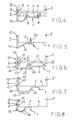
- Fig. 4-8 je ein weiteres Ausführungsbeispiel einer erfindungsgemäßen Dichtungsleiste in Stirnansicht.
- 1 is an end view of a sealing strip according to the invention according to a first embodiment in connection with the adjacent side edge area of a component,
- 2 shows a cross section through the sealing strip according to FIG. 1 in the state fixed to the component and installed in an adjacent wall body,
- Fig. 3 is a sectional view corresponding to FIG. 2, wherein the sealing strip is connected to another component, and
- Fig. 4-8 each another embodiment of a sealing strip according to the invention in front view.
Die in der Zeichnung dargestellte Dichtungsleiste besteht aus einem zweischenkeligen Profilkörper 1 in Form eines einstückigen Strangpreßteils aus einem geeigneten Kunststoff, z.B. Hart-PVC, aus Kautschuk oder aus einem geeigneten Metall, z.B. Aluminium. Der Profilkörper 1 kann ferner von einem Coextrusionskörper aus z.B. Hart- und Weich-PVC gebildet sein.The sealing strip shown in the drawing consists of a two-legged
Der eine Schenkel 2 des Querschnittsprofils der Dichtungsleiste bildet einen Abdichtungsschenkel, während der Schenkel 3 einen Halteschenkel bildet, der an einem Außenrand 4 eines in Fig. 1 nur mit diesem Außenrandbereich zur Darstellung kommenden Bauteils 5, insbesondere eines Tür-oder Fensterrahmens, festlegbar ist. Hierzu ist der Halteschenkel 3 mit sich über die Länge der Dichtungsleiste erstreckenden Rastnasen 6 und 7 in seinen beiden Endbereichen versehen, die einstükkig an seine dem Bauteil 5 zugewandte Seite angeformt sind und mit entsprechenden leistenförmigen Rastnasen 8 und 9 am Außenrand 4 des Bauteils 5 für eine dauerhafte Festlegung an diesem verrastet werden können, wie dies aus Fig. 1 ersichtlich ist. Auf seiner anderen Seite ist der Halteschenkel 3 gegenüber der Rastnase 6 mit einer weiteren, einstückig angeformten Rastnase 10 versehen, die zur Fixierung eines Mauerankers 11 vorgesehen ist, wie es im einzelnen in Verbindung mit Fig. 2 beschrieben ist.One
Der Abdichtungsschenkel 2 des Profilkörpers 1 ist mit einer äußeren Abschlußleiste 12 und einer inneren Verankerungsleiste 13 versehen, die aus der Hauptebene des Abdichtungsschenkels 2 in vom Bauteil 5 fortweisender Richtung abgewinkelt sind. Zwischen den beiden Leisten 12 und 13 ist die Außenfläche des Abdichtungsschenkels 2 mit einer Haftungsprofilierung 14 versehen.The sealing
Auf der dem Bauteil 5 zugewandten Seite ist der Abdichtungsschenkel 2 mit einer zum Bauteil 5 hin gerichteten Formausbildung 15 versehen, die bei dem Ausführungsbeispiel gemäß Fig. 1 von drei mit gegenseitigem Abstand voneinander einstückig an den Abdichtungsschenkel 2 angeformten Abdichtungsfahnen 16 gebildet ist, die mit ihren freien Stirnrändern im Einbauzustand des Profilkörpers 1 an der ihnen zugewandten Außenseite des Bauteils 5 zur Anlage kommen.On the side facing the
Der Übergangsbereich zwischen dem Abdichtungsschenkel 2 und dem Halteschenkel 3 ist von einem elastisch verformbaren Zwischensteg 17 eingenommen, der, ebenso wie der sich anschließende Abdichtungsschenkel 2, eine geringere Wanddicke aufweisen kann, wie dies das Ausführungsbeispiel gemäß Fig. 1 veranschaulicht. Durch die geringere Wanddicke hat der Zwischensteg 17 eine entsprechend vergrößerte elastische Verformbarkeit. Der Profilkörper 1 wird dabei so hergestellt, daß der von dem Zwischensteg 17 und dem Abdichtungsschenkel 2 gebildete elastische Bereich im Einbauzustand mit einer gewissen Vorspannung an die angrenzende Außenseite des Bauteils 5 gedrückt wird. Dies ist in Fig. 1 durch die Überschneidungen der Profilformen des Abdichtungsschenkels 2 und des Bauteils 5 in diesem Bereich veranschaulicht.The transition region between the
Zur Entfaltung seiner elastischen Verformbarkeit zum nachgiebigen Auffangen der im eingebauten Zustand temperaturbedingt auftretenden Dehnbewegungen des Bauteils bildet der Zwischensteg 17 vorteilhaft eine vom Bauteil 5 fortweisende Ablenkung von einer geradlinigen, in den Abdichtungsschenkel 2 einmündenden gedachten Verlängerungslinie des Halteschenkels 3, die bei dem Ausführungsbeispiel gemäß Fig. 1 bogenförmig ausgeführt ist. Der Zwischensteg 17 bildet auf diese Weise eine die einander zugewandten Enden des Halteschenkels 3 und des Abdichtungsschenkels 2 miteinander verbindende Materialbrücke, deren Materiallänge, im Querschnittsprofil des Profilkörpers 1 betrachtet, größer ist als der in gerader Verlängerung des Halteschenkels 3 gemessene Abstand zwischen diesem und dem Abdichtungsschenkel 2.In order to develop its elastic deformability in order to flexibly absorb the expansion movements of the component that occur due to the temperature in the installed state, the
Aus Fig. 2 ist der Einbauzustand des Bauteils 5, hier ein Fensterrahmen aus Kunststoff, ersichtlich. Das Bauteil 5 ist in eine schlitzförmige Öffnung 18 eines Wandkörpers 19 eingesetzt, der bei dem dargestellten Beispiel aus Mauerwerk 20 mit einer äußeren Putzschicht 21 besteht. Der die Dichtungsleiste bildende Profilkörper 1 ist mit dem Außenrand 4 des Bauteils 5 in der anhand der Fig. 1 beschriebenen Weise verrastet. Über eine ankerfeste Scheibe 22, die sich einenends an der Rastnase 10 abstützt, ist der Maueranker 11 am Profilkörper 1 mittels einer Schraube 23 festgelegt, die durch die Unterlegscheibe 22 hindurch in den Halteschenkel 3 der Dichtungsleiste eingeschraubt ist.2 shows the installed state of the
An der vom Bauteil 5 abgewandten Seite ist die Wandöffnung 18 von nachgiebigem Material, zum Beispiel von Glaswolle 24, ausgefüllt. Der Zwischensteg 17 steht damit weder mit dem Bauteil 5 noch mit dem Wandkörper 19 in unmittelbarem Abstützungseingriff, so daß der Zwischensteg 17 seine elastische Verformungsarbeit insoweit ungehindert ausführen kann, um die durch Temperaturunterschiede im Einbauzustand hervorgerufenen Dehnbewegungen des Bauteils 5, die insbesondere im Außenbereich auftreten, durch elastisches Nachgeben bzw. Rückstellen auszugleichen.On the side facing away from the
Die Putzschicht 21 ist an den Abdichtungsschenkel angeputzt, wobei der Anputzmörtel 25 aufgrund der Verankerungsleiste 13 und der Haftungsprofilierung 14 eine innige Verbindung mit dem Abdichtungsschenkel 2 eingeht. Die äußere Abschlußleiste 12 wird dabei als Putzkante benutzt. Diese hat eine definierte Lage zum Bauteil 5 bzw. zur Rahmenöffnung eines das Bauteil 5 beispielsweise bildenden Fensterrahmens, so daß dieser im eingeputzten Zustand durchgehend gleich breit von außen zu sehen ist.The
Die Befestigung des Profilkörpers 1 am Bauteil 5 kann bereits in der Werkstatt erfolgen, indem von einem endlosen Profilkörper-Strangvorrat den jeweiligen Profilkörper 1 bildende Teilstücke entsprechend der mit einer Dichtungsleiste auszurüstenden Seitenlänge des Bauteils 5 abgelängt und am Bauteil 5 durch Verrastung (Fig. 1 und 2) oder durch Verschraubung (Fig. 3) etc. festgelegt werden.The attachment of the
Gemäß den Ausführungsbeispiel nach Fig. 3 kommt der Profilkörper 1 in unveränderter Ausführung bei einem Bauteil 5' zum Einsatz, das hier von einem Fensterrahmen aus Holz gebildet ist. Der Halteschenkel 3 ist jedoch nicht mit dem Bauteil 5' verrastet, sondern mit Hilfe von Schrauben 26 verschraubt. Die Rastnasen 6 und 7 sind dabei in entsprechende Randnuten des Bauteils 5' eingelassen. Im übrigen gelten die gleichen Einbaubedingungen wie im Falle der Fig. 2, wie es durch die Verwendung gleicher Bezugszeichen für gleiche bzw. übereinstimmende Bauteile kenntlich gemacht ist.According to the embodiment of FIG. 3, the
Die Ausführungsform gemäß Fig. 3 kann als Beispiel für eine Altbausanierung gelten, bei der nach Möglichkeit auf ein erneutes Anputzen von außen verzichtet wird. Um hier die nötige Abdichtung zu erreichen, wird ein geeignetes Dichtband 27, beispielsweise aus wasserfest imprägniertem Schaumstoff, auf der Außenseite des Abdichtungsschenkels 2 mit Hilfe der Leisten 12 und 13 und der Haftungsprofilierung 14 festgelegt und die Einheit aus dem Bauteil 5' mit Dichtungsleiste und dem Dichtband 27 gegen den bauseitig vorhandenen Putz 21 gedrückt. Hierbei ist es auch möglich, den Zwischenraum zwischen dem Abdichtungsschenkel 2 und dem Putz 21 mit flüssig zu verarbeitenden Dichtmaterialien zu füllen. Diese werden bei Anwendung des Profilkörpers 1 als Dichtungsleiste nicht so stark belastet, da der größte Teil der im Einbauzustand auftretenden Dehnbewegungen durch den elastischen Zwischensteg 17 aufgefangen wird.The embodiment according to FIG. 3 can be used as an example for an old building renovation, in which, if possible, a new plastering from the outside is avoided. In order to achieve the necessary sealing here, a
Die in solchen Fällen unschöne äußere Dichtungszone kann durch eine von außen einschiebbare Deckleiste 28 verdeckt werden, die aus einem zweischenkeligen Profilkörper besteht, dessen Innenschenkel 29 zwischen die Außenseite des Bauteils 5' und die Innenseite des Abdichtungsschenkels 2 unter Verrastung mit den Abdichtungsfahnen 16 eingeschoben wird und dessen Außenschenkel 30 die Dichtungszone abdeckt.The outer seal zone, which is unsightly in such cases, can be covered by a
In den Fig. 4 bis 8 sind einige Abwandlungen des die Dichtungsleiste bildenden Profilkörpers 1 in Verbindung mit dem Bauteil 5 bzw. 5' dargestellt, die im folgenden hinsichtlich ihrer Unterschiedsmerkmale zu dem anhand der Fig. 1 beschriebenen Profilkörper 1 erläutert werden, wobei für gleiche bzw. übereinstimmende Elemente z.T. ohne erneute Beschreibung durchgehend die gleichen Bezugszeichen verwendet werden.4 to 8 show some modifications of the
Bei dem Profilkörper 1 gemäß Fig. 4 ist auf die äußere Rastnase 10 am Halteschenkel 3 verzichtet worden. Die Materialdicke des Halteschenkels 3 und des Zwischenstegs 17 mit dem sich daran nach außen anschließenden Abdichtungsschenkel 2 ist bei diesem wie auch bei den nachfolgenden Ausführungsbeispielen gleich gewählt worden. Die Haftungsprofilierung 14 des Abdichtungsschenkels 2 verzichtet auf die innere Verankerungsleiste 13 und ist anstelle der aus Fig. 1 ersichtlichen Rillungen von Wellungen mit diesen gegenüber größererem Radius gebildet. Diese Wellungen verlaufen, ebenso wie die Krümmung des Zwischenstegs 17, in vom Profilkörper 1 fortweisender Richtung.In the
Bei dem Ausführungsbeispiel gemäß Fig. 5 ist der Halteschenkel 3 ohne jede Rastnase ausgeführt. Der Halteschenkel 3 ist daher nur für eine Verschraubung, wie durch die Schraube 26 angedeutet, oder für eine Heftung oder Nagelung zur Verbindung mit dem Bauteil 5' aus Holz geeignet. Der Zwischensteg 17 ist vom Halteschenkel 3 schräg nach außen zum Ende des Abdichtungsschenkels 2 geführt, der gerade in einer zum Halteschenkel 3 senkrechten Ebene verläuft und mit Ausnahme der Leisten 12 und 13 auf eine Haftungsprofilierung an seiner Außenseite bzw. eine abdichtende Formausbildung auf seiner Innenseite verzichtet. Dieser Profilkörper 1 kann auch, ausgehend von einem Blechteil, durch einen Biegevorgang gebildet sein, was grundsätzlich für alle einfacheren Formen des Profilkörpers 1 gilt.In the embodiment shown in FIG. 5, the
Der Halteschenkel 3 des Ausführungsbeispiels gemäß Fig. 6 besitzt anstelle der rechtwinklig abgewinkelten inneren Rastnasen 6 und 7 innere Schrägansätze 31, die nach Art einer Keilverbindung an entsprechenden Schrägflächen 32 des Bauteils 5 in Eingriff gehalten sind. Der Abdichtungsschenkel 2 entspricht im wesentlichen dem des Ausführungsbeispiels gemäß Fig. 5, wobei jedoch an der Innenseite als abdichtende Formausbildung 15 verkürzte Abdichtungslippen 16' vorgesehen sind, deren freie Enden in einer gemeinsamen Ebene liegen, die mit einer linienförmigen Materialschwächung 33 in Form einer Kerbrille in der Abschlußleiste 12 zusammenfällt. Hierbei kann der Endstreifen der Abschlußleiste 12, der im Einbauzustand am Bauteil 5 anliegt beispielsweise nach Einritzen mit einem Messer leicht entfernt werden, um ein nachträgliches Einfügen der Deckleiste 28 zu erleichtern. Der Zwischensteg 17 besitzt bei dieser Ausführungsform eine von Verbindungsansätzen 34 zum Abdichtungsschenkel 2 bzw. Halteschenkel 3 ausgehende leicht geschwungene Ausbildung mit zum Bauteil 5 hin gerichteter konvexer Wölbung.6 has instead of the right-angled
Bei dem Ausführungsbeispiel gemäß Fig. 7 mit für eine Verschraubung, Nagelung oder Heftung ausgebildetem Halteschenkel 3 sind die Ansatzschenkel 34 des Zwischenteils 17 gegenüber der Ausführungsform gemäß Fig. 6 in vom Bauteil 5' fortweisender Richtung verlängert und der Bereich zwischen den Ansätzen 34 ist M-förmig profiliert. In ähnlicher Weise hat der Abdichtungsschenkel 2 eine Zackenprofilierung mit am Bauteil 5' zur Anlage kommenden Abdichtungsrippen 35, während die Außenseite des Abdichtungsschenkels 2 die Haftungsprofilierung 14 bildet.In the exemplary embodiment according to FIG. 7 with a holding
Der Abdichtungsschenkel 2 gemäß dem Ausführungsbeispiel nach Fig. 8 besitzt eine ähnliche Profilierung wie der Abdichtungsschenkel 2 gemäß Fig. 7, die jedoch nicht zacken-, sondern eher wellenförmig ausgebildet ist. Der Zwischensteg 17 besitzt gemäß Fig. 8 eine Dehnungsprofilierung 36 durch versetzt zueinander eingeformte Kerbrillen auf seinen beiden Seiten.The sealing
Es versteht sich, daß die beschriebenen und zeichnerisch dargestellten Ausführungsformen in ihren Merkmalen nicht nur in der in der Zeichnung jeweils dargestellten Form ausgeführt, sondern auch in demgegenüber unterschiedlicher Weise in ihren Einzelmerkmalen miteinander kombiniert werden können, wobei insbesondere der Zwischensteg 17 bei jeder der dargestellten Profilformen mit einer Dehnungsprofilierung wie der Dehnungsprofilierung 36 versehen sein kann, um die elastische Verformbarkeit des Zwischenstegs 17 ggf. weiter zu verbessern. In den Fällen, in denen der Profilkörper 1 nach dem Coextrusionsverfahren aus unterschiedlich harten Materialien hergestellt ist,ist das weichere Material den Dichtungsbereichen zugeordnet.It is understood that the described and graphically illustrated embodiments are not only executed in their characteristics in the form shown in the drawing, but can also be combined in their individual characteristics in different ways, in particular the
Claims (12)
Applications Claiming Priority (2)
| Application Number | Priority Date | Filing Date | Title |
|---|---|---|---|
| DE9011667U DE9011667U1 (en) | 1990-08-10 | 1990-08-10 | Plastic sealing strip for sealing door and window frames or similar components |
| DE9011667U | 1990-08-10 |
Publications (1)
| Publication Number | Publication Date |
|---|---|
| EP0470603A1 true EP0470603A1 (en) | 1992-02-12 |
Family
ID=6856408
Family Applications (1)
| Application Number | Title | Priority Date | Filing Date |
|---|---|---|---|
| EP91113291A Withdrawn EP0470603A1 (en) | 1990-08-10 | 1991-08-08 | Sealing means for window and door frames |
Country Status (2)
| Country | Link |
|---|---|
| EP (1) | EP0470603A1 (en) |
| DE (1) | DE9011667U1 (en) |
Cited By (4)
| Publication number | Priority date | Publication date | Assignee | Title |
|---|---|---|---|---|
| WO1994027018A1 (en) * | 1993-05-08 | 1994-11-24 | Anglian Windows Limited | Improvements in cavity closures |
| WO2005124085A2 (en) * | 2004-06-14 | 2005-12-29 | Jeld-Wen, Inc. | Cavity closers and wall ties |
| US8302353B2 (en) * | 2004-10-15 | 2012-11-06 | Thomas Bren | Water intrusion prevention method and apparatus |
| US20210230869A1 (en) * | 2016-05-20 | 2021-07-29 | Hilti Aktiengesellschaft | Thermal and acoustic insulating and sealing system for a safing slot in a curtain wall |
Families Citing this family (2)
| Publication number | Priority date | Publication date | Assignee | Title |
|---|---|---|---|---|
| DE19855241A1 (en) * | 1998-11-30 | 2000-05-31 | Huels Troisdorf | Method for fastening a frame using an assembly frame |
| DE102007022493B4 (en) * | 2007-05-14 | 2009-02-12 | Josef Hain Gmbh & Co. Kg | Window or door frame |
Citations (4)
| Publication number | Priority date | Publication date | Assignee | Title |
|---|---|---|---|---|
| US1585717A (en) * | 1924-12-04 | 1926-05-25 | S H Thomson Mfg Company | Sash lock |
| US1929633A (en) * | 1929-12-13 | 1933-10-10 | Charles P Gifford | Frame for building openings |
| DE3311142A1 (en) * | 1983-03-26 | 1984-10-04 | Hans 4550 Bramsche Schmidt | Sealing strip for sealing gap-shaped intermediate spaces between the outside of window frames and adjoining masonry |
| DE3419742C1 (en) * | 1984-05-26 | 1985-08-22 | Heinz 6750 Kaiserslautern Spies | Screed for plastering |
-
1990
- 1990-08-10 DE DE9011667U patent/DE9011667U1/en not_active Expired - Lifetime
-
1991
- 1991-08-08 EP EP91113291A patent/EP0470603A1/en not_active Withdrawn
Patent Citations (4)
| Publication number | Priority date | Publication date | Assignee | Title |
|---|---|---|---|---|
| US1585717A (en) * | 1924-12-04 | 1926-05-25 | S H Thomson Mfg Company | Sash lock |
| US1929633A (en) * | 1929-12-13 | 1933-10-10 | Charles P Gifford | Frame for building openings |
| DE3311142A1 (en) * | 1983-03-26 | 1984-10-04 | Hans 4550 Bramsche Schmidt | Sealing strip for sealing gap-shaped intermediate spaces between the outside of window frames and adjoining masonry |
| DE3419742C1 (en) * | 1984-05-26 | 1985-08-22 | Heinz 6750 Kaiserslautern Spies | Screed for plastering |
Cited By (6)
| Publication number | Priority date | Publication date | Assignee | Title |
|---|---|---|---|---|
| WO1994027018A1 (en) * | 1993-05-08 | 1994-11-24 | Anglian Windows Limited | Improvements in cavity closures |
| WO2005124085A2 (en) * | 2004-06-14 | 2005-12-29 | Jeld-Wen, Inc. | Cavity closers and wall ties |
| WO2005124085A3 (en) * | 2004-06-14 | 2006-10-05 | Jeld Wen Inc | Cavity closers and wall ties |
| US8302353B2 (en) * | 2004-10-15 | 2012-11-06 | Thomas Bren | Water intrusion prevention method and apparatus |
| US20210230869A1 (en) * | 2016-05-20 | 2021-07-29 | Hilti Aktiengesellschaft | Thermal and acoustic insulating and sealing system for a safing slot in a curtain wall |
| US11808036B2 (en) * | 2016-05-20 | 2023-11-07 | Hilti Aktiengesellschaft | Thermal and acoustic insulating and sealing system for a safing slot in a curtain wall |
Also Published As
| Publication number | Publication date |
|---|---|
| DE9011667U1 (en) | 1990-10-18 |
Similar Documents
| Publication | Publication Date | Title |
|---|---|---|
| EP1811111B1 (en) | Window opening with a window frame and a sealing strip | |
| EP1285143B1 (en) | Shaped bar for establishing a junction between a structural member and a building surface | |
| EP1674649B1 (en) | Two-part connecting section for plaster adjoining construction elements | |
| DE20008712U1 (en) | Profile strip for sealing a movement joint between a component and a plaster layer | |
| AT396497B (en) | BUILDING EXTERNAL COVERING, PARTICULARLY FACADE, WITH PANEL-SHAPED COMPONENTS | |
| DE29508614U1 (en) | Seal for the joint between window or door frame and external masonry of buildings | |
| EP0470603A1 (en) | Sealing means for window and door frames | |
| DE3201083C2 (en) | Covering device, in particular for a base joint | |
| EP2762668B1 (en) | Connection profile | |
| DE29922126U1 (en) | Profile arrangement | |
| EP2492429B1 (en) | Staff angle and building corner with staff angle | |
| DE19544077C2 (en) | Glazing resistant to heat | |
| EP2171175A1 (en) | Plaster connecting strip for the reveal of windows and doors | |
| DE9410234U1 (en) | Profile set for all-round performance of window and door elements on the structure | |
| DE202015100167U1 (en) | Clamping profile for a windowsill and windowsill closure | |
| DE102013012374B4 (en) | On-board profile for mounting a window sill and kit for thermally insulated installation of such | |
| DE4422153C1 (en) | Frame for connection fittings for doors and windows | |
| DE60202279T2 (en) | FRAME FOR FIXING A PLATE-TABLE TABLE | |
| DE1658983C3 (en) | Sealing for expansion joints | |
| DE10361083A1 (en) | Arrangement and method for sealing joints in buildings, in particular of expansion joints in an external facade | |
| EP2374961A2 (en) | Plastering strip | |
| DE9215573U1 (en) | Butt joint | |
| DE3528388A1 (en) | Elastic profile seal for insulating glazings | |
| DE3700201A1 (en) | Adjusting device for aligning door frames, window frames or the like in a building opening | |
| DE202013006699U1 (en) | On-board profile for mounting a window sill and kit for thermally insulated installation of such |
Legal Events
| Date | Code | Title | Description |
|---|---|---|---|
| PUAI | Public reference made under article 153(3) epc to a published international application that has entered the european phase |
Free format text: ORIGINAL CODE: 0009012 |
|
| AK | Designated contracting states |
Kind code of ref document: A1 Designated state(s): AT BE CH DE DK ES FR GB GR IT LI LU NL SE |
|
| 17P | Request for examination filed |
Effective date: 19920807 |
|
| 17Q | First examination report despatched |
Effective date: 19930811 |
|
| STAA | Information on the status of an ep patent application or granted ep patent |
Free format text: STATUS: THE APPLICATION IS DEEMED TO BE WITHDRAWN |
|
| 18D | Application deemed to be withdrawn |
Effective date: 19940825 |