EP0331690B1 - Ceiling facing - Google Patents
Ceiling facing Download PDFInfo
- Publication number
- EP0331690B1 EP0331690B1 EP88907303A EP88907303A EP0331690B1 EP 0331690 B1 EP0331690 B1 EP 0331690B1 EP 88907303 A EP88907303 A EP 88907303A EP 88907303 A EP88907303 A EP 88907303A EP 0331690 B1 EP0331690 B1 EP 0331690B1
- Authority
- EP
- European Patent Office
- Prior art keywords
- struts
- ceiling facing
- longitudinal
- extending
- cassette
- Prior art date
- Legal status (The legal status is an assumption and is not a legal conclusion. Google has not performed a legal analysis and makes no representation as to the accuracy of the status listed.)
- Expired - Lifetime
Links
- 238000007789 sealing Methods 0.000 claims description 25
- 230000007704 transition Effects 0.000 claims description 4
- 239000013013 elastic material Substances 0.000 claims description 2
- 229910052751 metal Inorganic materials 0.000 claims description 2
- 239000002184 metal Substances 0.000 claims description 2
- 239000007787 solid Substances 0.000 claims description 2
- 238000009434 installation Methods 0.000 description 10
- 238000005253 cladding Methods 0.000 description 9
- 230000000694 effects Effects 0.000 description 4
- 230000000007 visual effect Effects 0.000 description 4
- 229910052782 aluminium Inorganic materials 0.000 description 2
- XAGFODPZIPBFFR-UHFFFAOYSA-N aluminium Chemical compound [Al] XAGFODPZIPBFFR-UHFFFAOYSA-N 0.000 description 2
- 230000008901 benefit Effects 0.000 description 2
- 230000003287 optical effect Effects 0.000 description 2
- 238000003860 storage Methods 0.000 description 2
- 244000089486 Phragmites australis subsp australis Species 0.000 description 1
- 229910000831 Steel Inorganic materials 0.000 description 1
- 239000000853 adhesive Substances 0.000 description 1
- 230000001070 adhesive effect Effects 0.000 description 1
- 230000015572 biosynthetic process Effects 0.000 description 1
- 238000010276 construction Methods 0.000 description 1
- 230000002349 favourable effect Effects 0.000 description 1
- 239000006260 foam Substances 0.000 description 1
- 230000001771 impaired effect Effects 0.000 description 1
- 230000003993 interaction Effects 0.000 description 1
- 230000001788 irregular Effects 0.000 description 1
- 238000004519 manufacturing process Methods 0.000 description 1
- 238000012986 modification Methods 0.000 description 1
- 230000004048 modification Effects 0.000 description 1
- 239000003973 paint Substances 0.000 description 1
- 239000002245 particle Substances 0.000 description 1
- 238000003825 pressing Methods 0.000 description 1
- 230000000284 resting effect Effects 0.000 description 1
- 239000003566 sealing material Substances 0.000 description 1
- 239000010959 steel Substances 0.000 description 1
- 230000008719 thickening Effects 0.000 description 1
Images


Classifications
-
- E—FIXED CONSTRUCTIONS
- E04—BUILDING
- E04B—GENERAL BUILDING CONSTRUCTIONS; WALLS, e.g. PARTITIONS; ROOFS; FLOORS; CEILINGS; INSULATION OR OTHER PROTECTION OF BUILDINGS
- E04B9/00—Ceilings; Construction of ceilings, e.g. false ceilings; Ceiling construction with regard to insulation
- E04B9/06—Ceilings; Construction of ceilings, e.g. false ceilings; Ceiling construction with regard to insulation characterised by constructional features of the supporting construction, e.g. cross section or material of framework members
- E04B9/064—Ceilings; Construction of ceilings, e.g. false ceilings; Ceiling construction with regard to insulation characterised by constructional features of the supporting construction, e.g. cross section or material of framework members comprising extruded supporting beams
-
- E—FIXED CONSTRUCTIONS
- E04—BUILDING
- E04B—GENERAL BUILDING CONSTRUCTIONS; WALLS, e.g. PARTITIONS; ROOFS; FLOORS; CEILINGS; INSULATION OR OTHER PROTECTION OF BUILDINGS
- E04B9/00—Ceilings; Construction of ceilings, e.g. false ceilings; Ceiling construction with regard to insulation
- E04B9/06—Ceilings; Construction of ceilings, e.g. false ceilings; Ceiling construction with regard to insulation characterised by constructional features of the supporting construction, e.g. cross section or material of framework members
- E04B9/12—Connections between non-parallel members of the supporting construction
-
- E—FIXED CONSTRUCTIONS
- E04—BUILDING
- E04B—GENERAL BUILDING CONSTRUCTIONS; WALLS, e.g. PARTITIONS; ROOFS; FLOORS; CEILINGS; INSULATION OR OTHER PROTECTION OF BUILDINGS
- E04B9/00—Ceilings; Construction of ceilings, e.g. false ceilings; Ceiling construction with regard to insulation
- E04B9/18—Means for suspending the supporting construction
- E04B9/183—Means for suspending the supporting construction having a lower side adapted to be connected to a channel of the supporting construction
-
- E—FIXED CONSTRUCTIONS
- E04—BUILDING
- E04B—GENERAL BUILDING CONSTRUCTIONS; WALLS, e.g. PARTITIONS; ROOFS; FLOORS; CEILINGS; INSULATION OR OTHER PROTECTION OF BUILDINGS
- E04B9/00—Ceilings; Construction of ceilings, e.g. false ceilings; Ceiling construction with regard to insulation
- E04B9/22—Connection of slabs, panels, sheets or the like to the supporting construction
- E04B9/24—Connection of slabs, panels, sheets or the like to the supporting construction with the slabs, panels, sheets or the like positioned on the upperside of, or held against the underside of the horizontal flanges of the supporting construction or accessory means connected thereto
- E04B9/241—Connection of slabs, panels, sheets or the like to the supporting construction with the slabs, panels, sheets or the like positioned on the upperside of, or held against the underside of the horizontal flanges of the supporting construction or accessory means connected thereto with the slabs, panels, sheets or the like positioned on the upperside of the horizontal flanges of the supporting construction
- E04B9/242—Connection of slabs, panels, sheets or the like to the supporting construction with the slabs, panels, sheets or the like positioned on the upperside of, or held against the underside of the horizontal flanges of the supporting construction or accessory means connected thereto with the slabs, panels, sheets or the like positioned on the upperside of the horizontal flanges of the supporting construction with separate retaining elements
-
- E—FIXED CONSTRUCTIONS
- E04—BUILDING
- E04B—GENERAL BUILDING CONSTRUCTIONS; WALLS, e.g. PARTITIONS; ROOFS; FLOORS; CEILINGS; INSULATION OR OTHER PROTECTION OF BUILDINGS
- E04B9/00—Ceilings; Construction of ceilings, e.g. false ceilings; Ceiling construction with regard to insulation
- E04B9/30—Ceilings; Construction of ceilings, e.g. false ceilings; Ceiling construction with regard to insulation characterised by edge details of the ceiling; e.g. securing to an adjacent wall
-
- E—FIXED CONSTRUCTIONS
- E04—BUILDING
- E04F—FINISHING WORK ON BUILDINGS, e.g. STAIRS, FLOORS
- E04F13/00—Coverings or linings, e.g. for walls or ceilings
- E04F13/07—Coverings or linings, e.g. for walls or ceilings composed of covering or lining elements; Sub-structures therefor; Fastening means therefor
- E04F13/08—Coverings or linings, e.g. for walls or ceilings composed of covering or lining elements; Sub-structures therefor; Fastening means therefor composed of a plurality of similar covering or lining elements
- E04F13/12—Coverings or linings, e.g. for walls or ceilings composed of covering or lining elements; Sub-structures therefor; Fastening means therefor composed of a plurality of similar covering or lining elements of metal or with an outer layer of metal or enameled metal
Definitions
- the invention relates to a gas and dust-tight ceiling cladding made of metal, consisting of a rigid support grid and cassettes arranged in the grid fields of the support grid, wherein the support grid is made up of continuous longitudinal struts and transverse struts connected to them, and each longitudinal strut and each cross strut in each Longitudinally extending and arranged on both sides at their lower end, substantially horizontally extending projections, on the top of which are arranged seals on which the cassettes lie sealingly.
- an intermediate ceiling which has longitudinal and transverse struts which are suspended from node pieces. Since the struts are held at the junctions only by their own weight, these elements are not fixed. In addition, the longitudinal and transverse struts are only roll-formed profiles that are not torsionally rigid, so that the false ceiling can be twisted and the necessary gas tightness can no longer be guaranteed. Like the longitudinal and cross struts, the cassettes are only held by their own weight. This can have a particularly disadvantageous effect if excess pressure is used in the rooms suspended with this false ceiling, since the cassettes can be raised due to the lack of fixation. The same applies, for example, to sterile ceilings in laboratories if a vacuum is created in the ceiling cavity to extract dirt particles.
- GB-A-2087451 describes a suspended ceiling in which cross members are fastened to the longitudinal members via a snap-in connection.
- a locking lug is provided on the cross member and a corresponding recess is provided on the longitudinal member.
- a very precise design of the catch and recess is required, as well as correspondingly precise and therefore complex assembly. If the locking lug is pressed too deep into the recess, the cross member is higher than the longitudinal member, so that there is no precisely defined position of the carrier in this blanket. In addition, the flush mounting of cassettes and support system is not guaranteed with this false ceiling.
- the invention has for its object to provide a ceiling cladding of the type mentioned, which allows a stable, optically appealing and gas-tight cladding even with variable grid dimensions with simple construction and easy assembly and disassembly of the cassettes.
- the object is achieved in that the lateral projections of the longitudinal struts and the cross struts or the longitudinal struts and cross struts themselves are each formed from box-shaped, torsionally rigid profiles.
- the projections on the top have at least one upwardly extending web which runs along the respective projection.
- the seals are between the web and the side wall of the struts or can also be accommodated between them in the case of a plurality of webs.
- the cassettes of spring elements are pressed onto the webs, the spring elements being supported on the side walls of the struts.
- the depth and contour of the cassettes are designed such that their closed bottom surfaces are arranged flush with the struts.
- the ceiling covering according to the invention is characterized by a number of considerable advantages.
- Another important advantage of the invention is that the weight of the cassettes does not rest directly on the seals, as is known from the prior art, but is carried by the webs, while the seals are only in contact with corresponding surfaces of the cassettes to create a gastight seal to guarantee. Damage to the seals is thus avoided.
- the cassettes since the cassettes always rest completely on the respective webs, it is also ensured that the seals on the entire circumference of the cassettes are in engagement, so that a gas-tight seal is ensured. Furthermore, the seal is protected against damage even when the cassette is removed and is not visible, in particular when the cassette is inserted, so that the overall visual impression is not impaired. Finally, the cassettes are always held in their inserted position by the spring elements fixing them.
- the seal can also have a rectangular cross section and be designed as a solid profile, it proving to be advantageous if the sealing material as a whole has sufficient elasticity.
- the seal In order to connect the seal to the projection in a secure manner, it preferably has a flat contact surface which can be glued to the projection, for example.
- This flat contact surface can be provided both in the case of a tubular seal and in the case of a rectangular seal.
- the seal is preferably made of an elastic material with a closed surface manufactured, for example from a closed-cell foam or the like.
- a further web can be arranged parallel to the web between the web and the wall of the longitudinal strut or the cross strut. This further web is used to form a U-shaped channel cross section, in which the seal is inserted.
- This design measure prevents spring elements which are arranged on the longitudinal web and on the cross web from being able to damage the seal.
- the cassette can prove to be advantageous for the cassette to have a circumferential step fold on its outer lower edge region, the cassette resting with the horizontal surface of the step fold on the projections or the webs.
- the formation of the step fold makes it possible to arrange the lower surface of the cassette flush with the lower surfaces of the longitudinal struts and transverse struts.
- the spring elements fixing the cassettes in their position on the longitudinal struts and / or on the cross struts are designed as leaf springs, the ends of these leaf springs being held in opposing grooves formed on the side walls of the longitudinal or cross struts.
- the spring elements thus bring about a firm support of the cassettes on the webs of the projections, so that the cassettes lie exactly on the optical point of view and are pressed into contact with the seals with regard to the required sealing effect.
- the springs have an angled section between the two ends, one leg of which extends essentially vertically, is resiliently supported on the side surface of the cassette and up to approximately runs at the level of the upper edge of the cassette, and its other leg runs above the upper edge of the cassette and is angled outwardly with respect to the side wall of the strut. It can furthermore prove to be advantageous if one leg is adjoined by a leg which preferably extends in a straight line towards the lower groove and on the other leg a leg which preferably extends in a straight line to the upper groove. Furthermore, a spring end section, which runs parallel to the side wall of the strut, can connect to the legs of the tongue that extend toward the grooves. All of these configurations improve the pressing of the cassettes against the webs and ensure an adequate seal.
- the invention provides that the grid fields at the transition area to a wall are delimited by a wall connecting strut. This configuration gives the possibility of even irregular wall shapes in a sealing connection to the Bring ceiling paneling. It may also be favorable that the wall connection strip has a horizontal projection extending in its longitudinal direction, on the upper side of which a seal which can be brought into contact with the cassette is arranged. This configuration ensures that a gas-tight seal is also present in the transition area to the wall.
- a second projection parallel to this is arranged above the first projection, below which a horizontal region of the cassette can be inserted. The cassette is thus guided and held in a U-shaped groove, thus moving the cassette or unintentionally loosening is excluded.
- the seal has a U-shaped cross section and is mounted on the second projection and comprises at least one sealing lip pointing in the direction of the first projection.
- the sealing lip is in contact with the horizontal area of the cassette and enables a gas-tight seal. Since the sealing lip extends into the U-shaped area between the first and the second projection, a sufficient pretensioning force of the seal is ensured at the same time.
- the cassette is provided with internally mounted internals which can be designed, for example, in the form of a lamp or an air supply / air discharge device. This proves to be advantageous because no additional leakage points are possible due to additional internals or attachments.
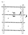
- the ceiling covering according to the invention consists essentially of horizontally arranged, mutually parallel longitudinal struts 2, of cross struts 4, which are arranged between the longitudinal struts 2 and are each fastened with their ends to the longitudinal struts, and of cassettes 6, of the longitudinal struts 2 and the cross struts 4 are worn.
- the longitudinal struts 2 are above one another from the upper side 12 of the longitudinal struts 2 supporting straps 14 extending at the top are fastened to supports 8, which in turn are height-adjustable, for example by means of threaded rods 16, relative to the ceiling, not shown.
- the support straps 14 of the longitudinal struts 2 are angled at their upper end, so that the longitudinal struts can be suspended from the supports 8 via the horizontally extending angle leg 18 of the support strap 14.
- the support straps 14 are secured to the supports 8 by means of screws 20.
- the longitudinal struts 2 and the cross struts 4 are designed as aluminum profiles.
- the cassettes 6 carried by the longitudinal struts 2 and the cross struts 4 are made of electrolytically galvanized sheet steel, the visible sides of both the cassettes 6 and the longitudinal struts 2 and the cross struts 4 being coated with thermally hardened paint, for example in the color RAL 9010.
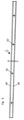
- the shape of the longitudinal struts 2 can be seen in particular from FIG. 3.
- the longitudinal struts 2 are designed essentially as a rectangular box section, the upper side 12 of the box section being largely open so that the inside of the box section is accessible.
- Continuous, laterally projecting supports 26 are formed on the two longitudinal sides 22, 24 of the box section in the longitudinal direction of the longitudinal struts. These supports 26 are also designed in the manner of a box profile, the underside 28 of the supports 26 being in one plane with the underside 30 of the longitudinal strut 2 in the manner of a box profile.
- Three vertical webs 34, 36, 38, which extend in the longitudinal direction of the longitudinal strut 2, are each formed on the upward-facing upper side 32 of each support 26, the outer web 34 extending the side wall 40 of the box-shaped support 26 represents, the web 38 is arranged near the longitudinal side 22 of the longitudinal strut 2 and with this defines a groove 42 and the web 36 is arranged between the web 34 and the web 38.
- a sealing strip 44 is inserted, which can be made of rubber, for example, extends over the entire length of the longitudinal strut and, in the non-compressed state, projects slightly beyond the upper edges of the webs 34, 36.
- a web 46 is formed, which runs parallel to the long sides and over the entire length of the long sides and defines a groove 48 between them and the adjacent side wall 22 or 24.
- the opposing grooves 42, 48 serve to receive springs 50 to be described in more detail below.
- galvanized grate angles with additional diagonal struts are provided as thrust beams at a distance of, for example, 100 cm.
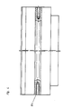
- the structure of the cross struts 4 can be seen in particular from FIG. 2.
- the cross struts 4 are also designed as an aluminum profile and comprise an upright ledge 80, along the lower end of which on both sides in the longitudinal direction of the bar 80 extending supports 56 are formed, which extend to both sides of the line 80 and whose undersides 58 form the underside of the cross struts.
- the supports 56 have the same cross-section as the supports 26 of the longitudinal struts 2 and are therefore designed in the manner of a box profile with side walls 70 and upper sides 62, from which webs 64, 66, 68 extending in the longitudinal direction extend upwards, between the webs 64, 66 Sealing strips 74 are arranged, and wherein grooves 72 are formed between the webs 68 and the adjacent side surface of the strip 80.
- longitudinally extending, downwardly pointing webs 76 are formed which define grooves 78 between themselves and the adjacent side faces of the strip 80.
- the opposing grooves 72, 78 serve, as in the case of the longitudinal struts 2, for receiving the ends of springs 50.
- a stiffening bar 60 running at right angles to the level of the bar 80 is formed along the upper edge of the cross bars 4.
- the strip 80 has a thickening 82 extending approximately in the center in the longitudinal direction, in which a threaded bore 84 extending in the longitudinal direction of the cross strut 4 is formed in the center.
- the cross struts 4 are provided at their lower end edges with a step-shaped, rectangular recess 86 which is dimensioned such that the cross struts 4 when attached to the longitudinal struts 2 with the upper, horizontal surface of the recess 86 on the Support 26 and at the same time rest with their end face 87 on the outer sides of the webs 46 of the longitudinal struts 2.
- the width of the cross struts 4 can be approximately 4 cm and the height of the cross struts 4 corresponds the height of the longitudinal struts 2 and is thus 7.2 cm.
- the screws 54 are guided from the inside of the longitudinal struts 2 through the through bores 52 of the longitudinal sides 22, 24 of the longitudinal struts 2 and screwed into the threaded bores 84 of the cross struts 4 opposite the through bores 52.
- the dimensions of the cassettes 6 are somewhat smaller than the grid dimensions defined by the long sides 22, 24 of the longitudinal struts and the outer sides of the strip 80 of the cross struts, but larger than the grid dimensions defined by the side walls 40, 70 of the supports 26, 56.
- the cassettes 6 are provided with a circumferential step fold 88 at the bottom.
- the cassettes 6 When the cassettes 6 are inserted into the grid fields 10 defined by the longitudinal struts 2 and the cross struts 4, they lie with the horizontal surfaces 90 of the step fold 88 in a sealing manner on the sealing strips 44, 74 carried by the supports 26, 56.
- the height of the step fold 88 is designed so that the undersides 92 are flush with the undersides of the longitudinal struts 2 and the cross struts 4.
- the springs 50 carried on the longitudinal struts 2 and the cross struts 4 are provided to fix the position of the cassettes 6.
- the springs 50 each have a leg running parallel to the longitudinal sides 22, 24 or the strip 80 at their two ends, the lower leg of the spring 50 in the groove 42 or 72 and the upper leg of the spring 50 in the upper Groove 48 and 78 is guided.
- a vertical leg 94 is formed on the springs 50, which bears against the side wall of the cassette 6 in the region of its upper edge, up to the region of the upper edge 96 of the cassette extends and rests under tension on the cassette.
- This vertical leg of the spring 50 is adjoined by a short leg 98, which extends obliquely upward on the outside.
- a straight leg 100 leads to the upper end region of the tongue 50, which is guided in the groove 48 or 78.
- a straight leg 102 of the tongue 50 leads to the lower, in of the groove 42 and 72 guided end portion of the spring 50th
- the springs 50 are distributed on the longitudinal struts 2 and the cross struts 4 for each cassette 6.
- the springs 50 can be inserted into the guide grooves in a simple manner by compressing the legs 100, 102 at the desired location.
- the springs 50 can also be moved within the guide grooves if necessary.
- the lower edges of the cassettes 6 run onto the legs 100 of the springs 50 and push them to the side.
- the springs snap with their legs 98, 100 to the outside over the upper edge of the cassettes 6 while at the same time the vertical legs 94 rest against the side surfaces of the cassette 6. In this way, the Cassettes 6 held securely in their target position.
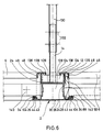
- FIG. 6 shows a sectional view, similar to FIG. 3, through a longitudinal strut of the support grid according to the invention, which essentially corresponds in structure to the longitudinal strut shown in FIG. 3.
- the same parts have been given the same reference numbers.
- the longitudinal strut shown in Fig. 6 has on the projections 26 each upwardly extending webs 34 on which, as shown, the cassettes 6 with a horizontal surface of the Step fold 88 rest. It is thus ensured that the cassettes are always in contact with the webs 34, so that an exact assignment and alignment of the arrangement of the undersides 30 of the longitudinal struts and the undersides of the cassettes 6 is ensured.
- a seal 44 is arranged which has a flat lower contact surface 104 which can be connected to a horizontal region of the projection 26, for example by means of an adhesive connection.
- the seal 44 is essentially tubular and in the unloaded state has a height which is greater than the corresponding height of the web 34. In this way it is ensured that the seal 44 is always compressed to a predetermined extent when the cassettes 6 are placed on it .
- the longitudinal strut shown in FIG. 6 is designed in the form of a hollow profile and has an essentially rectangular, closed conduit channel 124, which is formed by the underside 30, the longitudinal sides 24 and a horizontally running separating web 126.
- the conduit 124 is thus self-contained and sealed against a tubular cross-sectional area 128 arranged above it.
- the tubular cross-sectional area essentially has a U-shaped configuration, so that the mounting bracket 14 can be inserted into it, as shown in FIG. 6.
- the conduit 124 can be used to pass electrical cables or pipes, for example for a sprinkler system. Due to its sealing by means of the separating web 126, it is also possible to add attachments to the underside 30 of the longitudinal strut 2, for example dividing walls, additional lights or the like, without this affecting the tightness of the ceiling cladding would.
- the carrying strap 14 is connected to a hanger 130, it being possible for the connection to be made by means of bolts or screws 132 which are only indicated schematically.
- upper and lower grooves 48, 42 are formed, which are used to hold a spring 50 or a spring element.
- An embodiment of such a spring element 50 is shown on the right half of FIG. 6.
- the support bracket 14 In order to ensure secure attachment to the support bracket 14, it has a lower transverse region, from the outer upper edge view of which retaining tabs 136 extend upwards, which can be introduced into U-shaped grooves which are formed by edges 138 of the top sides 12. Thus, loosening of the support bracket 14 is reliably prevented even when vibrations occur.
- a connection between the longitudinal strut 2 and a cross strut 4 can take place by means of an angle 140, which is formed in a longitudinal groove 142 of the longitudinal side 24 of the longitudinal strut 2.
- the angle 140 can be screwed to the longitudinal strut 2, for example.
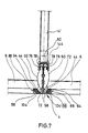
- FIG. 7 shows an embodiment, similar to FIG. 2, of a cross strut according to the invention, which corresponds in terms of its lateral structure to the longitudinal strut shown in FIG. 6.
- the webs 64 are designed such that the cassettes with their step fold 88 rest directly on the webs 64, but not on the seals 44.
- the seal 44 is the same Formed as in the embodiment shown in Fig. 6.
- the upper and lower grooves 78, 72 for receiving the spring elements 50 are formed in the same way.
- the cross strut shown in Fig. 7 can be suspended by means of a support bracket 14 ', which has at its lower end a holding element 144 which has a substantially U-shaped cross section, by means of which a gripping of the upper region of the cross strut is possible.
- the free ends of the holding element 144 are bent inwards in order to engage behind the webs 76. Since both the spring 50 and the support straps 14 'each extend only over a limited length of the cross strut, no undesirable interaction occurs between them.
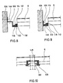
- FIGS. 8 and 9 show exemplary embodiments of a wall end strut according to the invention, by means of which a wall connection of a cassette 6 can be designed to suit the local conditions.
- the cassette 6 is provided with a horizontal region 116, which can be designed, for example, in the form of part of the underside of the cassette 6.
- the wall connection strut 106 has a first horizontal projection 110, on which the horizontal region 116 of the cassette 6 can be placed. This configuration ensures secure storage of the cassette 6. Essentially parallel to the first projection 110, a second projection 114 is formed in one piece with the wall connection strut 106, at the free end of which a seal 112 is arranged, which engages around the second projection 114 and has at least one sealing lip 118 on its underside, which seals against the first Bias 110 biased is. When the horizontal region 116 is inserted, a seal is thus made in a reliable manner.
- the wall connection strut 106 can be designed in the form of an angle profile which can be screwed to a wall 108. However, it is also possible to design the wall connection strut 106 in the form of a double-angle profile, as shown in FIG. 8, in order to form a shadow groove 146 in this way.
- FIG. 10 shows an exemplary embodiment of an installation for a cassette 6.
- the installation is in the form of a pipe 148, only shown schematically, which can be used, for example, for a sprinkler system.
- an annular seal 149 is inserted, which comprises an annular sealing lip 150 which is in contact with the outer surface of the tube 148 and thus represents a reliable seal.
- the tube 148 can either be attached to the cassette 6 or to a ceiling arranged above it.
- FIG. 11 shows a further exemplary embodiment of an installation of a cassette 6, which is designed in the form of a lamp 120 which is only shown schematically.
- the lamp 120 is firmly connected to the cassette 6 and has a housing which is closed toward the top. A gas-tight seal between the lamp 120 and the cassette 6 takes place via a seal 152.
- the lamp 120 is installed or removed together with the cassette 6.
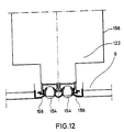
- FIG. 12 shows a further exemplary embodiment of an installation of a cassette, the installation being designed in the form of an air supply or air discharge device 122.
- a box 158 of the air installation 122 is via seals 156, which are tightly connected to the cassette 6, for Sealed top of the cassette, the seals 156 also serve to hold air nozzles 154. With this embodiment it is also possible to firmly connect the air installation 122 to the cassette.
- FIG. 13 shows a perspective bottom view of a ceiling covering according to the invention, cassettes 6 being inserted between the longitudinal struts 2 and the cross struts 4, some of which are provided with light fixtures 120 or air fixtures 122.
Landscapes
- Engineering & Computer Science (AREA)
- Architecture (AREA)
- Civil Engineering (AREA)
- Structural Engineering (AREA)
- Physics & Mathematics (AREA)
- Electromagnetism (AREA)
- Supports For Pipes And Cables (AREA)
- Road Signs Or Road Markings (AREA)
- Vehicle Interior And Exterior Ornaments, Soundproofing, And Insulation (AREA)
- Filtering Of Dispersed Particles In Gases (AREA)
- Securing Globes, Refractors, Reflectors Or The Like (AREA)
- Rod-Shaped Construction Members (AREA)
- Arrangement Of Elements, Cooling, Sealing, Or The Like Of Lighting Devices (AREA)
- Buffer Packaging (AREA)
Abstract
Description
Die Erfindung betrifft eine gas- und staubdichte Deckenverkleidung aus Metall, bestehend aus einem starren Trägerraster und aus in den Rasterfeldern des Trägerrasters angeordneten Kassetten, wobei das Trägerraster aus durchlaufenden Längsstreben und mit diesen verbundenen Querstreben aufgebaut ist und wobei jede Längsstrebe und jede Querstrebe jeweils in deren Längsrichtung verlaufende und beidseitig an deren unterem Ende angeordnete, sich im wesentlichen horizontal erstreckende Vorsprünge aufweist, auf deren Oberseite Dichtungen angeordnet sind, auf welchen die Kassetten dichtend aufliegen.The invention relates to a gas and dust-tight ceiling cladding made of metal, consisting of a rigid support grid and cassettes arranged in the grid fields of the support grid, wherein the support grid is made up of continuous longitudinal struts and transverse struts connected to them, and each longitudinal strut and each cross strut in each Longitudinally extending and arranged on both sides at their lower end, substantially horizontally extending projections, on the top of which are arranged seals on which the cassettes lie sealingly.
Bei gasdichten Deckenverkleidungen, wie sie insbesondere im klinischen Bereich, im Laborbereich oder in als Reinsträume ausgestalteten Fertigungsräumen verwendet werden, ist es erforderlich, daß das Trägerraster so ausgebildet ist, daß die Kassetten sich in vollständig dichtender Anlage an dem Trägerraster befinden, zugleich aber leicht zu montieren oder zu demontieren sind. Weiterhin müssen derartige Deckenverkleidungen hohen optischen Ansprüchen genügen, d.h. es muß insbesondere bei sehr großflächigen Deckenverkleidungen eine exakte Anordnung der Kassetten möglich sein.In the case of gas-tight ceiling claddings, as are used in particular in clinical areas, in the laboratory area or in production rooms designed as clean rooms, it is necessary for the support grid to be designed in such a way that the cassettes are in a completely sealing arrangement on the support grid, but at the same time are easy to assemble or disassemble. Furthermore, such ceiling cladding must meet high visual standards, i.e. it must be possible to arrange the cassettes precisely, particularly in the case of very large ceiling claddings.
Aus der DE-PS 2624956 ist eine Unterdecke bekannt, bei welcher an den Vorsprüngen der Streben die Dichtungen so aufgebracht sind, daß die Kassetten direkt auf den Dichtungen aufliegen. Dies weist den Nachteil auf, daß die Dichtungen von dem Gewicht der Kassetten voll belastet werden und somit stark zusammengepreßt werden. Die Gleichmäßigkeit der Auflage der Kassetten kann, bedingt durch die Elastizität der Dichtungen, nicht soweit gewährleistet werden, daß die Deckenverkleidung in vollem Umfang den optischen Anforderungen gerecht wird. Weiterhin ist, bedingt durch die direkte Auflage, die allseitige Abdichtung der Kassetten nicht gewährleistet.From DE-PS 2624956 a false ceiling is known, in which the seals are applied to the projections of the struts so that the cassettes lie directly on the seals. This has the disadvantage that the seals are fully loaded by the weight of the cassettes and are therefore pressed together strongly. The uniformity of the cassette support can, due to the elasticity of the seals, cannot be guaranteed to the extent that the ceiling cladding fully meets the visual requirements. Furthermore, due to the direct support, the all-round sealing of the cassettes is not guaranteed.
Aus der DE-A 3142451 ist eine Zwischendecke bekannt, die Längs- und Querstreben aufweist, die an Knotenstücken eingehängt sind. Da die Streben praktisch nur durch ihr Eigengewicht an den Knotenpunkten gehalten sind, fehlt es an einer Fixierung dieser Elemente. Zudem handelt es sich bei den Längs- und Querstreben lediglich um rollgeformte Profile, die nicht verwindungssteif sind, so daß es zur Verwindung der Zwischendecke kommen kann und die notwendige Gasdichtigkeit nicht mehr gewährleistet ist. Wie die Längs- und Querstreben werden auch die Kassetten lediglich durch ihr Eigengewicht gehalten. Dies kann sich insbesondere dann sehr nachteilig auswirken, wenn in den mit dieser Zwischendecke abgehängten Räumen mit Überdruck gearbeitet wird, da die Kassetten aufgrund fehlender Fixierung angehoben werden können. Gleiches gilt beispielsweise bei sterilen Decken in Laboratorien wenn im Deckenhohlraum ein Unterdruck zum Absaugen von Schmutzpartikeln erzeugt wird.From DE-A 3142451 an intermediate ceiling is known which has longitudinal and transverse struts which are suspended from node pieces. Since the struts are held at the junctions only by their own weight, these elements are not fixed. In addition, the longitudinal and transverse struts are only roll-formed profiles that are not torsionally rigid, so that the false ceiling can be twisted and the necessary gas tightness can no longer be guaranteed. Like the longitudinal and cross struts, the cassettes are only held by their own weight. This can have a particularly disadvantageous effect if excess pressure is used in the rooms suspended with this false ceiling, since the cassettes can be raised due to the lack of fixation. The same applies, for example, to sterile ceilings in laboratories if a vacuum is created in the ceiling cavity to extract dirt particles.
In der GB-A-2087451 ist eine Unterdecke beschrieben, bei der Querträger über eine Rastverbindung an den Längsträgern befestigt werden. Hierzu ist am Querträger eine Rastnase, am Längsträger eine entsprechende Aussparung vorgesehen. Um eine funktionsfähige gasdichte Unterdecke zu erhalten, ist allerdings eine sehr präzise Ausbildung von Rastnase und Aussparung erforderlich, ebenso wie entsprechend genaue und damit aufwendige Montage. Wird die Rastnase zu tief in die Aussparung eingedrückt, liegt der Querträger höher als der Längsträger, so daß es bei dieser Decke an einer genau definierten Lage der Träger fehlt. Im übrigen ist auch die Deckenbündigkeit von Kassetten und Tragsystem bei dieser Unterdecke nicht gewährleistet.GB-A-2087451 describes a suspended ceiling in which cross members are fastened to the longitudinal members via a snap-in connection. For this purpose, a locking lug is provided on the cross member and a corresponding recess is provided on the longitudinal member. In order to obtain a functional, gas-tight false ceiling, however, a very precise design of the catch and recess is required, as well as correspondingly precise and therefore complex assembly. If the locking lug is pressed too deep into the recess, the cross member is higher than the longitudinal member, so that there is no precisely defined position of the carrier in this blanket. In addition, the flush mounting of cassettes and support system is not guaranteed with this false ceiling.
Der Erfindung liegt die Aufgabe zugrunde, eine Deckenverkleidung der eingangs genannten Art zu schaffen, welche bei einfachem Aufbau und einfacher Montage- und Demontagemöglichkeit der Kassetten eine stabile, optisch ansprechende und gasdichte Verkleidung auch bei variablen Rastermaßen ermöglicht.The invention has for its object to provide a ceiling cladding of the type mentioned, which allows a stable, optically appealing and gas-tight cladding even with variable grid dimensions with simple construction and easy assembly and disassembly of the cassettes.
Erfindungsgemäß wird die Aufgabe dadurch gelöst, daß die seitlichen Vorsprünge der Längsstreben und der Querstreben oder die Längsstreben und Querstreben selbst jeweils aus kastenförmigen, verwindungssteifen Profilen gebildet sind. Hierbei weisen die Vorsprünge an der Oberseite wenigstens einen nach oben erstreckenden Steg auf, der längs des jeweiligen Vorsprungs verläuft. Die Dichtungen sind bei der Erfindung zwischen dem Steg und der Seitenwand der Streben oder können auch bei mehreren Stegen zwischen diesen aufgenommen sein. Schließlich werden die Kassetten von Federelementen auf die Stege gedrückt, wobei die Federelemente sich an den Seitenwänden der Streben abstützen. Die Kassetten sind hierbei in ihrer Tiefe und Kontur derart ausgestaltet, daß ihre geschlossenen Bodenflächen mit den Streben flächenbündig angeordnet sind.According to the invention the object is achieved in that the lateral projections of the longitudinal struts and the cross struts or the longitudinal struts and cross struts themselves are each formed from box-shaped, torsionally rigid profiles. Here, the projections on the top have at least one upwardly extending web which runs along the respective projection. In the invention, the seals are between the web and the side wall of the struts or can also be accommodated between them in the case of a plurality of webs. Finally, the cassettes of spring elements are pressed onto the webs, the spring elements being supported on the side walls of the struts. The depth and contour of the cassettes are designed such that their closed bottom surfaces are arranged flush with the struts.
Die erfindungsgemäße Deckenverkleidung zeichnet sich durch eine Reihe erheblicher Vorteile aus. So ist es erfindungsgemäß möglich, die jeweiligen Kassetten direkt auf Stegen des Trägerrasters zu lagern, so daß zum einen eine gleichmäßige und sichere Lagerung der Kassetten gewährleistet ist, und zum anderen stets eine exakte, auch den optischen Anforderungen gerecht werdende Zuordnung zwischen den Kassetten und dem Trägerraster erzielbar ist, wobei die Kassetten und das Trägerraster flächenbündig angeordnet sind, was den optischen Eindruck noch verbessert. Ein weiterer wesentlicher Vorteil der Erfindung liegt darin, daß das Gewicht der Kassetten nicht, wie aus dem Stand der Technik bekannt, direkt auf den Dichtungen aufliegt, sondern von den Stegen getragen wird, während die Dichtungen sich nur in Anlage an entsprechenden Flächen der Kassetten befinden, um eine gasdichte Abdichtung zu gewährleisten. Eine Beschädigung der Dichtungen wird somit vermieden. Weiterhin ist, da die Kassetten stets vollständig auf den jeweiligen Stegen aufliegen, auch sichergestellt, daß sich die Dichtungen am gesamten Umfang der Kassetten in Eingriff mitbefinden, so daß eine gasdichte Abdichtung gewährleistet ist. Desweiteren ist die Dichtung auch bei abgenommener Kassette gegen Beschädigungen geschützt und ist insbesondere bei eingelegter Kassette nicht sichtbar, so daß der optische Gesamteindruck nicht beeinträchtigt wird. Schließlich werden die Kassetten durch die sie fixierenden Federelemente stets in ihrer eingesetzten Position gehalten.The ceiling covering according to the invention is characterized by a number of considerable advantages. Thus, it is possible according to the invention to store the respective cassettes directly on webs of the carrier grid, so that on the one hand a uniform and secure storage of the cassettes is ensured and on the other hand always an exact assignment, which also meets the optical requirements, between the cassettes and the Carrier grid is achievable, the cassettes and the carrier grid being arranged flush, which further improves the visual impression. Another important advantage of the invention is that the weight of the cassettes does not rest directly on the seals, as is known from the prior art, but is carried by the webs, while the seals are only in contact with corresponding surfaces of the cassettes to create a gastight seal to guarantee. Damage to the seals is thus avoided. Furthermore, since the cassettes always rest completely on the respective webs, it is also ensured that the seals on the entire circumference of the cassettes are in engagement, so that a gas-tight seal is ensured. Furthermore, the seal is protected against damage even when the cassette is removed and is not visible, in particular when the cassette is inserted, so that the overall visual impression is not impaired. Finally, the cassettes are always held in their inserted position by the spring elements fixing them.
Um eine gute und gleichmäßige Abdichtwirkung zu erzielen, kann es sich als vorteilhaft erweisen, die Dichtung schlauchartig auszubilden und im unbelasteten Zustand mit einer Höhe zu versehen, die größer als die Höhe des Stegs ist. Die Dichtung wird somit in einem vorgegebenen Maß durch die Kassette verformt, wobei die Elastizität der Dichtung zu einer ausreichenden Anlage gegen die Fläche der Kassette führt, um die Dichtwirkung sicherzustellen.In order to achieve a good and uniform sealing effect, it can prove to be advantageous to design the seal in a hose-like manner and to provide it in the unloaded state with a height that is greater than the height of the web. The seal is thus deformed to a predetermined extent by the cassette, the elasticity of the seal resulting in sufficient abutment against the surface of the cassette to ensure the sealing effect.
Die Dichtung kann erfindungsgemäß auch einen rechteckigen Querschnitt aufweisen und als Vollprofil ausgebildet sein, wobei es sich dann als vorteilhaft erweist, wenn das Dichtungsmaterial insgesamt eine ausreichende Elastizität aufweist.According to the invention, the seal can also have a rectangular cross section and be designed as a solid profile, it proving to be advantageous if the sealing material as a whole has sufficient elasticity.
Um die Dichtung in sicherer Weise mit dem Vorsprung zu verbinden, weist diese bevorzugterweise eine ebene Auflagefläche auf, welche beispielsweise mit dem Vorsprung verklebbar ist. Diese ebene Auflagefläche kann sowohl bei einer schlauchartigen als auch bei einer rechteckförmigen Dichtung vorgesehen sein.In order to connect the seal to the projection in a secure manner, it preferably has a flat contact surface which can be glued to the projection, for example. This flat contact surface can be provided both in the case of a tubular seal and in the case of a rectangular seal.
Um eine gasdichte Abdichtung zu gewährleisten, ist die Dichtung bevorzugterweise aus einem elastischen Material mit einer geschlossenen Oberfläche gefertigt, beispielsweise aus einem geschlossenporigen Schaumstoff oder ähnlichem.In order to ensure a gas-tight seal, the seal is preferably made of an elastic material with a closed surface manufactured, for example from a closed-cell foam or the like.
In einer Weiterentwicklung der Erfindung kann parallel zu dem Steg zwischen diesem und der Wandung der Längsstrebe bzw. der Querstrebe ein weiterer Steg angeordnet sein. Dieser weitere Steg dient zur Ausbildung eines U-förmigen Kanalquerschnitts, in welchen die Dichtung eingelegt ist.In a further development of the invention, a further web can be arranged parallel to the web between the web and the wall of the longitudinal strut or the cross strut. This further web is used to form a U-shaped channel cross section, in which the seal is inserted.
Durch diese Ausgestaltungsmaßnahme wird verhindert, daß Federelemente, welche an dem Längssteg und an dem Quersteg angeordnet sind, die Dichtung beschädigen können.This design measure prevents spring elements which are arranged on the longitudinal web and on the cross web from being able to damage the seal.
Weiterhin kann es sich als günstig erweisen, daß die Kassette an ihrem äußeren unteren Randbereich einen umlaufenden Stufenfalz aufweist, wobei die Kassette mit der horizontalen Fläche des Stufenfalzes auf den Vorsprüngen bzw. den Stegen aufliegt. Durch die Ausbildung des Stufenfalzes ist es möglich, die untere Fläche der Kassette bündig zu den Unterflächen der Längsstreben und Querstreben anzuordnen.Furthermore, it can prove to be advantageous for the cassette to have a circumferential step fold on its outer lower edge region, the cassette resting with the horizontal surface of the step fold on the projections or the webs. The formation of the step fold makes it possible to arrange the lower surface of the cassette flush with the lower surfaces of the longitudinal struts and transverse struts.
In einer bevorzugten Ausführungsform sind die an den Längsstreben und/oder an den Querstreben, die Kassetten in ihrer Position fixierenden Federelemente als Blattfedern ausgebildet, wobei die Enden dieser Blattfedern in an den Seitenwänden der Längs- bzw. Querstreben ausgebildeten, sich gegenüberliegenden Nuten gehalten sind. Bei dieser Federausgestaltung ist ein Einsetzen bzw. ein Entfernen der Kassetten besonders einfach möglich, ein die Demontage der Kassetten verhinderndes Verklemmen kann in sicherer Weise ausgeschlossen werden.In a preferred embodiment, the spring elements fixing the cassettes in their position on the longitudinal struts and / or on the cross struts are designed as leaf springs, the ends of these leaf springs being held in opposing grooves formed on the side walls of the longitudinal or cross struts. With this spring configuration, the cassettes can be inserted or removed in a particularly simple manner; jamming preventing the cassette from being dismantled can be ruled out in a safe manner.
Weiterhin kann es sich als vorteilhaft erweisen, daß die Nuten von der jeweiligen Seitenwand und einer hierzu parallel verlaufenden, vom oberen Ende der Seitenwand nach unten verlaufenden Leiste einerseits und einer auf der Oberseite des Vorsprungs ausgebildeten, nach oben parallel zur Seitenwand verlaufenden Leiste andererseits gebildet sind.Furthermore, it can prove to be advantageous that the grooves on the one hand and a strip running parallel to it and running downward from the upper end of the side wall on the one hand and one on the top of the On the other hand, protrusion-shaped bar extending upwards parallel to the side wall are formed.
Bei dieser Ausgestaltung ist eine sichere Halterung und Fixierung der Federelemente gewährleistet. Die Federelemente bewirken somit eine feste Auflage der Kassetten auf den Stegen der Vorsprünge, so daß die Kassetten sowohl in optischer Hinsicht exakt aufliegen, als auch hinsichtlich der erforderlichen Dichtwirkung in Anlage mit den Dichtungen gedrückt werden.With this configuration, a secure mounting and fixing of the spring elements is guaranteed. The spring elements thus bring about a firm support of the cassettes on the webs of the projections, so that the cassettes lie exactly on the optical point of view and are pressed into contact with the seals with regard to the required sealing effect.
Um die Halterung und Klemmung der Kassetten auf die Stege weiter zu verbessern, kann erfindungsgemäß vorgesehen sein, daß die Federn zwischen den beiden Enden einen abgewinkelten Abschnitt aufweisen, dessen einer Schenkel im wesentlichen vertikal verläuft, sich an der Seitenfläche der Kassette federnd abstützt und bis etwa in Höhe der oberen Kante der Kassette verläuft, und dessen anderer Schenkel oberhalb der oberen Kante der Kassette verläuft und bezüglich der Seitenwand der Strebe schräg nach oben außen abgewinkelt ist. Dabei kann es sich weiterhin als günstig erweisen, wenn sich an den einen Schenkel ein sich vorzugsweise geradlinig zur unteren Nut hin erstreckender Schenkel und an den anderen Schenkel ein sich vorzugsweise geradlinig zur oberen Nut hin erstreckender Schenkel anschließt. Weiterhin kann sich an die sich zu den Nuten hin erstreckenden Schenkel der Feder je ein Feder-Endabschnitt anschließen, der parallel zur Seitenwand der Strebe verläuft. Durch alle diese Ausgestaltungsformen wird das Andrücken der Kassetten gegen die Stege verbessert und eine ausreichende Abdichtung sichergestellt.In order to further improve the mounting and clamping of the cassettes on the webs, it can be provided according to the invention that the springs have an angled section between the two ends, one leg of which extends essentially vertically, is resiliently supported on the side surface of the cassette and up to approximately runs at the level of the upper edge of the cassette, and its other leg runs above the upper edge of the cassette and is angled outwardly with respect to the side wall of the strut. It can furthermore prove to be advantageous if one leg is adjoined by a leg which preferably extends in a straight line towards the lower groove and on the other leg a leg which preferably extends in a straight line to the upper groove. Furthermore, a spring end section, which runs parallel to the side wall of the strut, can connect to the legs of the tongue that extend toward the grooves. All of these configurations improve the pressing of the cassettes against the webs and ensure an adequate seal.
Da die Größe der Rasterfelder bzw. die Dimensionierung des Trägerrasters vielfach nicht exakt an die Größe der abzudeckenden Decke angepaßt werden kann, ist erfindungsgemäß vorgesehen, daß die Rasterfelder am Übergangsbereich zu einer Wand durch eine Wandanschlußstrebe begrenzt sind. Durch diese Ausgestaltung wird die Möglichkeit gegeben, auch unregelmäßige Wandformen in einen dichtenden Anschluß an die Deckenverkleidung zu bringen. Dabei kann es weiterhin günstig sein, daß die Wandanschlußleiste einen sich in deren Längsrichtung erstreckenden, horizontalen Vorsprung aufweist, an dessen Oberseite eine mit der Kassette in Anlage bringbare Dichtung angeordnet ist. Durch diese Ausgestaltung wird erreicht, daß auch im Übergangsbereich zu der Wand eine gasdichte Abdichtung vorliegt.Since the size of the grid fields or the dimensioning of the support grid can often not be adapted exactly to the size of the ceiling to be covered, the invention provides that the grid fields at the transition area to a wall are delimited by a wall connecting strut. This configuration gives the possibility of even irregular wall shapes in a sealing connection to the Bring ceiling paneling. It may also be favorable that the wall connection strip has a horizontal projection extending in its longitudinal direction, on the upper side of which a seal which can be brought into contact with the cassette is arranged. This configuration ensures that a gas-tight seal is also present in the transition area to the wall.
In einer weiteren Ausgestaltung der Wandabschlußstrebe kann vorgesehen sein, daß über dem ersten Vorsprung ein zu diesem paralleler zweiter Vorsprung angeordnet ist, unter welchen ein horizontaler Bereich der Kassette einschiebbar ist. Die Kassette wird somit in einer U-förmigen Nut geführt und gehalten, ein Verschieben der Kassette oder ein unbeabsichtigtes Lösen ist somit ausgeschlossen.In a further embodiment of the wall end strut it can be provided that a second projection parallel to this is arranged above the first projection, below which a horizontal region of the cassette can be inserted. The cassette is thus guided and held in a U-shaped groove, thus moving the cassette or unintentionally loosening is excluded.
Zur sicheren Abdichtung im Übergangsbereich zur Wand kann weiterhin vorgesehen sein, daß die Dichtung einen U-förmigen Querschnitt aufweist und an dem zweiten Vorsprung gelagert ist und zumindest eine in Richtung auf den ersten Vorsprung weisende Dichtungslippe umfaßt. Die Dichtungslippe befindet sich in montiertem Zustand in Anlage an dem horizontalen Bereich der Kassette und ermöglicht eine gasdichte Abdichtung. Da sich die Dichtungslippe in den U-förmigen Bereich zwischen dem ersten und dem zweiten Vorsprung erstreckt, ist zugleich eine ausreichende Vorspannkraft der Dichtung gewährleistet.For secure sealing in the transition area to the wall, it can further be provided that the seal has a U-shaped cross section and is mounted on the second projection and comprises at least one sealing lip pointing in the direction of the first projection. When installed, the sealing lip is in contact with the horizontal area of the cassette and enables a gas-tight seal. Since the sealing lip extends into the U-shaped area between the first and the second projection, a sufficient pretensioning force of the seal is ensured at the same time.
In einer weiteren besonders günstigen Ausgestaltungsform der Erfindung ist vorgesehen, daß die Kassette mit dicht an dieser gelagerten Einbauten versehen ist, welche beispielsweise in Form einer Leuchte oder einer Luftzufuhr-/Luftabfuhreinrichtung ausgebildet sein können. Dies erweist sich deshalb als vorteilhaft, weil keine zusätzlichen Undichtigkeitsstellen durch zusätzliche Einbauten oder Anbauten möglich sind.In a further particularly advantageous embodiment of the invention, it is provided that the cassette is provided with internally mounted internals which can be designed, for example, in the form of a lamp or an air supply / air discharge device. This proves to be advantageous because no additional leakage points are possible due to additional internals or attachments.
Im folgenden wird die Erfindung anhand von Ausführungsbeispielen in Verbindung mit der Zeichnung beschrieben. Dabei zeigt:
- Fig. 1
- eine Unteransicht auf einen Teil des erfindungsgemäßen Trägerrasters,
- Fig. 2
- eine Teil-Schnittansicht durch eine Querstrebe des Trägerrasters entlang der Linie II/II von Fig. 1, mit eingesetzten Kassetten,
- Fig. 3
- eine Schnittansicht entlang der Linie III/III gemäß Fig. 1 durch eine Längsstrebe des Trägerrasters mit eingesetzter Kassette,
- Fig. 4
- eine Seitenansicht einer Querstrebe gemäß Fig. 1, teils im Schnitt,
- Fig. 5
- eine Seitenansicht einer Längsstrebe gemäß Fig. 1,
- Fig. 6
- eine Schnittansicht eines weiteren Ausführungsbeispiels einer Längsstrebe, ähnlich Fig. 3,
- Fig. 7
- eine Schnittansicht durch ein weiteres Ausführungsbeispiel einer Querstrebe, ähnlich Fig. 2,
- Fig. 8
- eine Seiten-Schnittansicht eines ersten Ausführungsbeispiels einer Wandabschlußstrebe,
- Fig. 9
- eine Ansicht ähnlich Fig. 8 eines weiteren Ausführungsbeispiels einer Wandabschlußstrebe,
- Fig. 10
- eine Schnittansicht durch eine Kassette mit einem Einbau in Form eines Rohres,
- Fig. 11
- eine Schnittansicht durch eine Kassette mit einem Einbau in Form einer Leuchte,
- Fig. 12
- eine Schnittansicht durch eine Kassette mit einem Einbau in Form eines Luftkastens und
- Fig. 13
- eine perspektivische Unteransicht einer mit Einbauten und Kassetten versehenen erfindungsgemäßen Dekkenverkleidung.
The invention is described below using exemplary embodiments in conjunction with the drawing. It shows:
- Fig. 1
- 2 shows a bottom view of part of the support grid according to the invention,
- Fig. 2
- 2 shows a partial sectional view through a cross strut of the support grid along the line II / II of FIG. 1, with inserted cassettes,
- Fig. 3
- 2 shows a sectional view along the line III / III according to FIG. 1 through a longitudinal strut of the support grid with the cassette inserted,
- Fig. 4
- 2 shows a side view of a cross strut according to FIG. 1, partly in section,
- Fig. 5
- 2 shows a side view of a longitudinal strut according to FIG. 1,
- Fig. 6
- 3 shows a sectional view of a further exemplary embodiment of a longitudinal strut, similar to FIG. 3,
- Fig. 7
- 3 shows a sectional view through a further exemplary embodiment of a cross strut, similar to FIG. 2,
- Fig. 8
- a sectional side view of a first embodiment of a wall end strut,
- Fig. 9
- 8 shows a view similar to FIG. 8 of a further exemplary embodiment of a wall end strut,
- Fig. 10
- 2 shows a sectional view through a cassette with an installation in the form of a tube,
- Fig. 11
- 2 shows a sectional view through a cassette with an installation in the form of a lamp,
- Fig. 12
- a sectional view through a cassette with an installation in the form of an air box and
- Fig. 13
- a perspective bottom view of a ceiling cladding according to the invention provided with internals and cassettes.
Die erfindungsgemäße Deckenverkleidung besteht im wesentlichen aus horizontal angeordneten, zueinander parallelen Längsstreben 2, aus Querstreben 4, die zwischen den Längsstreben 2 angeordnet sind und mit ihren Enden jeweils an den Längsstreben befestigt sind, sowie aus Kassetten 6, die von den Längsstreben 2 und den Querstreben 4 getragen sind. Wie aus Fig. 3 ersichtlich, sind die Längsstreben 2 über sich von der Oberseite 12 der Längsstreben 2 nach oben erstreckende Traglaschen 14 an Trägern 8 befestigt, die ihrerseits beispielsweise mittels Gewindestäben 16 relativ zur nicht dargestellten Raumdecke höhenverstellbar sind. Die Traglaschen 14 der Längsstreben 2 sind an ihrem oberen Ende abgewinkelt, so daß die Längsstreben über den sich horizontal erstreckenden Winkelschenkel 18 der Traglasche 14 an den Trägern 8 aufgehängt werden können. Zusätzlich werden die Traglaschen 14 mittels Schrauben 20 an den Trägern 8 gesichert.The ceiling covering according to the invention consists essentially of horizontally arranged, mutually parallel
Die Längsstreben 2 und die Querstreben 4 sind als Aluminium-Profile ausgebildet. Die von den Längsstreben 2 und den Querstreben 4 getragenen Kassetten 6 sind aus elektrolytisch verzinktem Stahlblech hergestellt, wobei die Sichtseiten sowohl der Kassetten 6 als auch der Längsstreben 2 und der Querstreben 4 mit thermogehärtetem Lack beispielsweise im Farbton RAL 9010 beschichtet sind.The
Die Form der Längsstreben 2 ist insbesondere aus Fig. 3 ersichtlich. Die Längsstreben 2 sind im wesentlichen als rechteckförmiges Kastenprofil ausgebildet, wobei die Oberseite 12 des Kastenprofils zum größten Teil geöffnet ist, damit das Innere des Kastenprofils zugänglich ist. An den beiden Längsseiten 22, 24 des Kastenprofils sind in Längsrichtung der Längsstreben verlaufende, durchgehende, seitlich vorspringende Auflager 26 angeformt. Diese Auflager 26 sind ebenfalls kastenprofilartig ausgebildet, wobei die Unterseite 28 der Auflager 26 in einer Ebene mit der Unterseite 30 der kastenprofilartigen Längsstrebe 2 liegt.The shape of the
An der nach oben weisenden Oberseite 32 eines jeden Auflagers 26 sind jeweils drei sich in Längsrichtung der Längsstrebe 2 erstreckende, vertikale Stege 34, 36, 38 ausgebildet, wobei der äußere Steg 34 eine Verlängerung der Seitenwand 40 des kastenprofilförmigen Auflagers 26 darstellt, der Steg 38 nahe der Längsseite 22 der Längsstrebe 2 angeordnet ist und mit dieser eine Nut 42 definiert und der Steg 36 zwischen dem Steg 34 und dem Steg 38 angeordnet ist.Three
Zwischen den Steg 34 und den Steg 36 ist ein Dichtungsstreifen 44 eingelegt, der beispielsweise aus Gummi bestehen kann, sich über die gesamte Länge der Längsstrebe erstreckt und im nicht komprimierten Zustand geringfügig über die Oberkanten der Stege 34, 36 hinausragt.Between the
Am oberen Bereich der beiden Längsseiten 22, 24 ist jeweils ein parallel zu den Längsseiten und über die gesamte Länge der Längsseiten verlaufender, nach unten gerichteter Steg 46 angeformt, der zwischen sich und der benachbarten Seitenwand 22 bzw. 24 jeweils eine Nut 48 definiert. Die sich gegenüberliegenden Nuten 42, 48 dienen zur Aufnahme von weiter unten noch näher zu beschreibenden Federn 50.On the upper area of the two
In den Längsseiten 22, 24 der Längsstreben 2 sind, wie aus Fig. 5 ersichtlich, etwa in halber Höhe unter einem jeweils vorgegebenen Rasterabstand von beispielsweise 60 cm Durchgangsbohrungen 52 zur Aufnahme von Schrauben 54 vorgesehen, welche zur kraftschlüssigen Befestigung der Querstreben 4 an den Längsstreben 2 dienen. Die Gesamtbreite der Längsstreben 2 einschließlich deren Auflager 26 kann etwa 10 cm betragen, bei einer Höhe von etwa 7,2 cm.In the
Zur Queraussteifung der Längsstreben sind im Abstand von beispielsweise 100 cm verzinkte Rostwinkel mit zusätzlichen Diagonalstreben als Schubtraversen vorgesehen.For the transverse stiffening of the longitudinal struts, galvanized grate angles with additional diagonal struts are provided as thrust beams at a distance of, for example, 100 cm.
Der Aufbau der Querstreben 4 ist insbesondere aus Fig. 2 ersichtlich. Die Querstreben 4 sind ebenfalls als Aluminiumprofil ausgebildet und umfassen eine hochkant stehende Leiste 80, längs deren unterem Ende beidseitig in Längsrichtung der Leiste 80 verlaufende Auflager 56 ausgebildet sind, die sich zu beiden Seiten der Leite 80 erstrecken und deren Unterseiten 58 die Unterseite der Querstreben bilden. Die Auflager 56 weisen den gleichen Querschnitt wie die Auflager 26 der Längsstreben 2 auf und sind demnach kastenprofilartig ausgebildet mit Seitenwänden 70 und Oberseiten 62, von denen sich in Längsrichtung verlaufende Stege 64, 66, 68 nach oben erstrecken, wobei zwischen den Stegen 64, 66 Dichtungsstreifen 74 angeordnet sind, und wobei zwischen den Stegen 68 und der benachbarten Seitenfläche der Leiste 80 Nuten 72 ausgebildet sind.The structure of the cross struts 4 can be seen in particular from FIG. 2. The cross struts 4 are also designed as an aluminum profile and comprise an
Längs des oberen Endes der Leiste 80 sind ähnlich wie im Falle der Längsstreben 2 in Längsrichtung verlaufende, nach unten weisende Stege 76 ausgebildet, die zwischen sich und den benachbarten Seitenflächen der Leiste 80 Nuten 78 definieren. Die sich gegenüberliegenden Nuten 72, 78 dienen, wie im Falle der Längsstreben 2, zur Aufnahme der Enden von Federn 50. Längs der oberen Kante der Querstreben 4 ist eine rechtwinklig zur Ebene der Leiste 80 verlaufende Versteifungsleiste 60 ausgebildet.Along the upper end of the
Die Leiste 80 weist in etwa mittig eine in deren Längsrichtung verlaufende Verdickung 82 auf, in der mittig eine in Längsrichtung der Querstrebe 4 verlaufende Gewindebohrung 84 ausgebildet ist. Wie aus Fig. 3 ersichtlich, sind die Querstreben 4 an ihren unteren Endkanten mit einer stufenförmigen, rechtwinkligen Ausnehmung 86 versehen, die so dimensioniert ist, daß die Querstreben 4 beim Ansetzen an die Längsstreben 2 mit der oberen, horizontalen Fläche der Ausnehmung 86 auf den Auflagern 26 aufliegen und mit ihrer Stirnfläche 87 gleichzeitig an den Außenseiten der Stege 46 der Längsstreben 2 anliegen. Die Breite der Querstreben 4 kann im Falle des hier beschriebenen Ausführungsbeispiels etwa 4 cm betragen und die Höhe der Querstreben 4 entspricht der Höhe der Längsstreben 2 und beträgt somit 7,2 cm.The
Zum Befestigen der Querstreben 4 an den Längsstreben 2 werden die Schrauben 54 vom Inneren der Längsstreben 2 durch die Durchgangsbohrungen 52 der Längsseiten 22, 24 der Längsstreben 2 hindurchgeführt und in die den Durchgangsbohrungen 52 gegenüberliegenden Gewindebohrungen 84 der Querstreben 4 eingedreht.To fasten the cross struts 4 to the
Die Abmessungen der Kassetten 6 sind etwas kleiner als die durch die Längsseiten 22, 24 der Längsstreben und die Außenseiten der Leiste 80 der Querstreben definierten Rastermaße, jedoch größer als die durch die Seitenwände 40, 70 der Auflager 26, 56 definierten Rastermaße. Längs ihrer Außenseiten sind die Kassetten 6 unten mit einem umlaufenden Stufenfalz 88 versehen. Wenn die Kassetten 6 in die durch die Längsstreben 2 und die Querstreben 4 definierten Rasterfelder 10 eingelegt sind, so liegen sie mit den horizontalen Flächen 90 des Stufenfalzes 88 auf den von den Auflagern 26, 56 getragenen Dichtungsstreifen 44, 74 dichtend auf. Die Höhe des Stufenfalzes 88 ist hierbei so ausgebildet, daß die Unterseiten 92 mit den Unterseiten der Längsstreben 2 und der Querstreben 4 bündig sind.The dimensions of the
Zur Fixierung der Position der Kassetten 6 sind die an den Längsstreben 2 und den Querstreben 4 getragenen Federn 50 vorgesehen. Die Federn 50 weisen an ihren beiden Enden jeweils einen parallel zu den Längsseiten 22, 24 bzw. der Leiste 80 verlaufenden Schenkel auf, wobei der untere Schenkel der Feder 50 in der Nut 42 bzw. 72 und der obere Schenkel der Feder 50 in der oberen Nut 48 bzw. 78 geführt ist. In ihrem mittleren Bereich ist an den Federn 50 ein vertikaler Schenkel 94 ausgebildet, der an der Seitenwand der Kassette 6 im Bereich deren oberen Kante anliegt, sich nach oben bis zum Bereich der oberen Kante 96 der Kassette erstreckt und unter Vorspannung an der Kassette anliegt. An diesen vertikalen Schenkel der Feder 50 schließt sich ein kurzer, schräg nach oben außen verlaufender Schenkel 98 an. Vom äußeren Ende dieses Schenkels 98 führt ein geradlinig verlaufender Schenkel 100 zum oberen, in der Nut 48 bzw. 78 geführten Endbereich der Feder 50. Vom unteren Ende des vertikalen Schenkels 94 führt ein geradlinig verlaufender, weiterer Schenkel 102 der Feder 50 zum unteren, in der Nut 42 bzw. 72 geführten Endabschnitt der Feder 50.The
Für jede Kassette 6 sind im Falle des hier beschriebenen Ausführungsbeispiels sechs Federn 50 an den Längsstreben 2 und den Querstreben 4 verteilt angeordnet. Die Federn 50 können in einfacher Weise durch Zusammendrücken der Schenkel 100, 102 an der gewünschten Stelle in die Führungsnuten eingesetzt werden. Auch können die Federn 50 bei Bedarf innerhalb der Führungsnuten verschoben werden. Beim Einsetzen der Kassetten 6 in die Rasterfelder 10 laufen die Unterkanten der Kassetten 6 auf den Schenkeln 100 der Federn 50 auf und drücken diese zur Seite. Sobald die Kassetten 6 ihre in den Figuren dargestellte Sollposition erreicht haben, schnappen die Federn mit ihren Schenkeln 98, 100 über der oberen Kante der Kassetten 6 nach außen bei gleichzeitiger Anlage der vertikalen Schenkel 94 an den Seitenflächen der Kassette 6. Auf diese Weise werden die Kassetten 6 sicher in ihrer Sollposition gehalten.In the case of the exemplary embodiment described here, six
In Fig. 6 ist eine Schnittansicht, ähnlich Fig. 3, durch eine Längsstrebe des erfindungsgemäßen Trägerrasters dargestellt, welche im wesentlichen im Aufbau der in Fig. 3 gezeigten Längsstrebe entspricht. Gleiche Teile wurden mit gleichen Bezugsziffern versehen. Die in Fig. 6 gezeigte Längsstrebe weist an den Vorsprüngen 26 jeweils sich nach oben erstreckende Stege 34 auf, auf welchen, wie dargestellt, die Kassetten 6 mit einer horizontalen Fläche des Stufenfalzes 88 aufliegen. Es ist somit sichergestellt, daß die Kassetten sich stets in Anlage mit den Stegen 34 befinden, so daß eine exakte Zuordnung und Fluchten der Anordnung der Unterseiten 30 der Längsstreben und der Unterseiten der Kassetten 6 gewährleistet ist. In dem zwischen der Längsseite 24 der Längsstrebe und dem Steg 34 ausgebildeten Zwischenraum ist eine Dichtung 44 angeordnet, welche eine ebene untere Auflagefläche 104 aufweist, die mit einem horizontalen Bereich des Vorsprungs 26 verbindbar ist beispielsweise mittels einer Klebverbindung. Die Dichtung 44 ist im wesentlichen schlauchförmig ausgebildet und weist im unbelasteten Zustand eine Höhe auf, welche größer ist, als die entsprechende Höhe des Steges 34. Auf diese Weise wird sichergestellt, daß beim Auflegen der Kassetten 6 die Dichtung 44 stets in vorgegebenem Maße zusammengedrückt wird.FIG. 6 shows a sectional view, similar to FIG. 3, through a longitudinal strut of the support grid according to the invention, which essentially corresponds in structure to the longitudinal strut shown in FIG. 3. The same parts have been given the same reference numbers. The longitudinal strut shown in Fig. 6 has on the
Die in Fig. 6 gezeigte Längsstrebe ist in Form eines Hohlprofiles ausgebildet und weist einen im wesentlichen rechteckigen, geschlossenen Leitungskanal 124 auf, welcher von der Unterseite 30, den Längsseiten 24 und einem horizontal verlaufenden Trennsteg 126 gebildet wird. Der Leitungskanal 124 ist somit in sich geschlossen und gegenüber einem über ihm angeordneten rohrförmigen Querschnittsbereich 128 abgedichtet. Der rohrförmige Querschnittsbereich weist im wesentlichen eine U-förmige Ausgestaltung auf, so daß in diesen die Traglasche 14 einführbar ist, so wie dies in Fig. 6 gezeigt ist.The longitudinal strut shown in FIG. 6 is designed in the form of a hollow profile and has an essentially rectangular,
Der Leitungskanal 124 kann zur Durchführung elektrischer Kabel oder von Rohren, beispielsweise für eine Sprinkleranlage verwendet werden. Durch seine Abdichtung mittels des Trennsteges 126 ist es weiterhin möglich, an der Unterseite 30 der Längsstrebe 2 Anbauten anzubringen, beispielsweise Trennwände, zusätzliche Leuchten oder ähnliches, ohne daß dadurch die Dichtigkeit der Deckenverkleidung beeinträchtigt würde.The
Die Traglasche 14 ist bei dem in Fig. 6 gezeigten Ausführungsbeispiel mit einem Aufhänger 130 verbunden, wobei die Verbindung mittels nur schematisch angedeuteter Bolzen oder Schrauben 132 erfolgen kann.In the exemplary embodiment shown in FIG. 6, the carrying
An der Längsstrebe sind, ebenso wie in dem in Fig. 3 gezeigten Ausführungsbeispiel obere und untere Nuten 48, 42 ausgebildet, welche zur Halterung einer Feder 50 oder eines Federelementes dienen. Auf der rechten Bildhälfte von Fig. 6 ist ein Ausführungsbeispiel, eines derartigen Federelementes 50 dargestellt.On the longitudinal strut, as in the exemplary embodiment shown in FIG. 3, upper and
Um eine sichere Befestigung an der Traglasche 14 sicherzustellen, weist diese einen unteren Querbereich auf, von dessen äußerer oberer Kantenaussicht sich Haltelaschen 136 nach oben erstrecken, welche in U-förmige Nuten einbringbar sind, die von Rändern 138 der Oberseiten 12 gebildet werden. Somit ist auch bei Auftreten von Schwingungen ein Lösen der Traglasche 14 sicher verhindert.In order to ensure secure attachment to the
Eine Verbindung zwischen der Längsstrebe 2 und einer Querstrebe 4 kann mittels eines Winkels 140 erfolgen, welcher in einer Längsnut 142 der Längsseite 24 der Längsstrebe 2 ausgebildet ist. Der Winkel 140 kann beispielsweise mit der Längsstrebe 2 verschraubt werden.A connection between the
In Fig. 7 ist ein Ausführungsbeispiel, ähnlich Fig. 2, einer erfindungsgemäßen Querstrebe dargestellt, welche hinsichtlich ihres seitlichen Aufbaus der in Fig. 6 gezeigten Längsstrebe entspricht. Auch bei dieser Querstrebe sind die Stege 64 so ausgebildet, daß die Kassetten mit ihrem Stufenfalz 88 direkt auf den Stegen 64, nicht jedoch auf den Dichtungen 44 aufliegen. Die Dichtung 44 ist in gleicher Weise ausgebildet, wie bei dem in Fig. 6 gezeigten Ausführungsbeispiel. Ebenso sind die oberen und unteren Nuten 78, 72 zur Aufnahme der Federelemente 50 in gleicher Weise ausgebildet.FIG. 7 shows an embodiment, similar to FIG. 2, of a cross strut according to the invention, which corresponds in terms of its lateral structure to the longitudinal strut shown in FIG. 6. Also in this cross strut, the
Die in Fig. 7 gezeigte Querstrebe ist mittels einer Traglasche 14′ aufhängbar, welche an ihrem unteren Ende ein Halteelement 144 aufweist, welches einen im wesentlichen U-förmigen Querschnitt aufweist, mittels dessen ein Umgreifen des oberen Bereiches der Querstrebe möglich ist. Die freien Enden des Halteelementes 144 sind, wie in Fig. 7 gezeigt, nach innen umgebogen, um die Stege 76 zu hintergreifen. Da sich sowohl die Feder 50 als auch die Traglaschen 14′ jeweils nur über eine beschränkte Länge der Querstrebe erstrecken, tritt zwischen diesen keine unerwünschte Wechselwirkung ein.The cross strut shown in Fig. 7 can be suspended by means of a support bracket 14 ', which has at its lower end a holding
In den Fig. 8 und 9 sind Ausführungsbeispiele einer erfindungsgemäßen Wandabschlußstrebe dargestellt, mittels derer ein Wandanschluß einer Kassette 6 passend zu den örtlichen Gegebenheiten ausgebildet sein kann. Die Kassette 6 ist mit einem horizontalen Bereich 116 versehen, welcher beispielsweise in Form eines Teils der Unterseite der Kassette 6 ausgebildet sein kann.8 and 9 show exemplary embodiments of a wall end strut according to the invention, by means of which a wall connection of a
Die Wandanschlußstrebe 106 weist einen ersten horizontalen Vorsprung 110 auf, auf welchen der horizontale Breich 116 der Kassette 6 auflegbar ist. Durch diese Ausgestaltung wird eine sichere Lagerung der Kassette 6 gewährleistet. Im wesentlichen parallel zu dem ersten Vorsprung 110 ist ein zweiter Vorsprung 114 einstückig mit der Wandanschlußstrebe 106 ausgebildet, an dessen freiem Ende eine Dichtung 112 angeordnet ist, welche den zweiten Vorsprung 114 umgreift und an ihrer Unterseite zumindest eine Dichtungslippe 118 aufweist, welche gegen den ersten Vorsprung 110 vorgespannt ist. Beim Einführen des horizontalen Bereichs 116 erfolgt somit in zuverlässiger Weise eine Abdichtung.The
Die Wandanschlußstrebe 106 kann, wie in Fig. 9 gezeigt, in Form eines Winkelprofiles ausgebildet sein, welches mit einer Wand 108 verschraubbar ist. Es ist jedoch auch möglich, die Wandanschlußstrebe 106, wie in Fig. 8 gezeigt, in Form eines Doppelwinkelprofiles auszugestalten, um auf diese Weise eine Schattennut 146 auszubilden.As shown in FIG. 9, the
In Fig. 10 ist ein Ausführungsbeispiel eines Einbaus für eine Kassette 6 dargestellt. Der Einbau ist in Form eines nur schematisch dargestellten Rohrs 148 ausgebildet, welches beispielsweise für eine Sprinkleranlage verwendbar ist. In eine Ausnehmung der Kassette 6 ist eine Ringdichtung 149 eingelegt, welche eine ringförmige Dichtlippe 150 umfaßt, die sich in Anlage an der Außenfläche des Rohrs 148 befindet und somit eine zuverlässige Abdichtung darstellt. Das Rohr 148 kann entweder an der Kassette 6 oder an einer darüber angeordneten Decke befestigt sein.10 shows an exemplary embodiment of an installation for a
In Fig. 11 ist ein weiteres Ausführungsbeispiel eines Einbaus einer Kassette 6 dargestellt, welcher in Form einer nur schematisch dargestellten Leuchte 120 ausgebildet ist. Die Leuchte 120 ist fest mit der Kassette 6 verbunden und weist ein zu der Oberseite hin geschlossenes Gehäuse auf. Über eine Dichtung 152 erfolgt eine gasdichte Abdichtung zwischen der Leuchte 120 und der Kassette 6. Die Leuchte 120 wird zusammen mit der Kassette 6 eingebaut bzw. demontiert.FIG. 11 shows a further exemplary embodiment of an installation of a
In Fig. 12 ist ein weiteres Ausführungsbeispiel eines Einbaus einer Kassette dargestellt, wobei der Einbau in Form einer Luftzufuhr-oder Luftabfuhreinrichtung 122 ausgebildet ist. Ein Kasten 158 des Lufteinbaus 122 ist über Dichtungen 156, welche dicht mit der Kassette 6 verbunden sind, zur Oberseite der Kassette hin abgedichtet, wobei die Dichtungen 156 zugleich zur Halterung von Luftdüsen 154 dienen. Auch bei dieser Ausgestaltungsform ist es möglich, den Lufteinbau 122 fest mit der Kassette zu verbinden.FIG. 12 shows a further exemplary embodiment of an installation of a cassette, the installation being designed in the form of an air supply or
In Fig. 13 ist eine perspektivische Unteransicht einer erfindungsgemäßen Deckenverkleidung dargestellt, wobei zwischen die Längsstreben 2 und die Querstreben 4 Kassetten 6 eingesetzt sind, welche teilweise mit Leuchteneinbauten 120 oder Lufteinbauten 122 versehen sind.FIG. 13 shows a perspective bottom view of a ceiling covering according to the invention,
Die Erfindung ist nicht auf die gezeigten Ausführungsbeispiele beschränkt, vielmehr ergeben sich im Rahmen der Erfindung vielfältige Abwandlungsmöglichkeiten.The invention is not limited to the exemplary embodiments shown, but there are many possible modifications within the scope of the invention.
Claims (18)
Priority Applications (1)
| Application Number | Priority Date | Filing Date | Title |
|---|---|---|---|
| AT88907303T ATE69632T1 (en) | 1987-08-18 | 1988-08-17 | CEILING PANEL. |
Applications Claiming Priority (2)
| Application Number | Priority Date | Filing Date | Title |
|---|---|---|---|
| DE8711244U DE8711244U1 (en) | 1987-08-18 | 1987-08-18 | Ceiling paneling |
| DE8711244U | 1987-08-18 |
Publications (2)
| Publication Number | Publication Date |
|---|---|
| EP0331690A1 EP0331690A1 (en) | 1989-09-13 |
| EP0331690B1 true EP0331690B1 (en) | 1991-11-21 |
Family
ID=6811195
Family Applications (2)
| Application Number | Title | Priority Date | Filing Date |
|---|---|---|---|
| EP88907303A Expired - Lifetime EP0331690B1 (en) | 1987-08-18 | 1988-08-17 | Ceiling facing |
| EP88907274A Expired - Lifetime EP0332672B1 (en) | 1987-08-18 | 1988-08-17 | Ceiling lining |
Family Applications After (1)
| Application Number | Title | Priority Date | Filing Date |
|---|---|---|---|
| EP88907274A Expired - Lifetime EP0332672B1 (en) | 1987-08-18 | 1988-08-17 | Ceiling lining |
Country Status (6)
| Country | Link |
|---|---|
| US (2) | US4944129A (en) |
| EP (2) | EP0331690B1 (en) |
| JP (2) | JPH02500531A (en) |
| KR (2) | KR890701854A (en) |
| DE (3) | DE8711244U1 (en) |
| WO (2) | WO1989001552A1 (en) |
Families Citing this family (21)
| Publication number | Priority date | Publication date | Assignee | Title |
|---|---|---|---|---|
| DE3802309A1 (en) * | 1988-01-27 | 1989-08-10 | Albrecht Ritter | CEILING WITH A SUSPENDED CARRIAGE |
| US5287668A (en) * | 1992-07-15 | 1994-02-22 | Capaul Corporation | Apparatus and method for refurbishing a ceiling grid to permit installation of ceiling panels |
| US5737888A (en) * | 1996-01-19 | 1998-04-14 | Heat-N-Glo Fireplace Products Inc. | Versatile surround trim structure |
| FR2745316B1 (en) * | 1996-02-22 | 1998-04-24 | Clestra Cleanroom Sa | SUSPENDED CEILING FOR WHITE ROOMS |
| DE19803080A1 (en) * | 1998-01-28 | 1999-07-29 | Meissner & Wurst | Ceiling grid for clean rooms |
| US6351920B1 (en) * | 1999-04-22 | 2002-03-05 | Clean Pak International, Inc. | Ceiling module perimeter seal |
| US7260919B1 (en) * | 2002-04-16 | 2007-08-28 | Daw Technologies, Inc. | Sealable ceiling assembly |
| DE60310652T2 (en) * | 2002-07-30 | 2007-10-04 | Hunter Douglas Industries B.V. | Panel construction for suspended ceilings |
| US6701686B1 (en) * | 2003-01-16 | 2004-03-09 | Worthington Armstrong Venture | Ceiling grid with seal |
| US6779315B1 (en) * | 2003-05-15 | 2004-08-24 | Vincent J. Bongio | Suspended ceiling/raised floor connection system |
| US8051612B2 (en) * | 2007-01-10 | 2011-11-08 | Woodard Kramer E | Wall system having biasing members retaining panels to posts that are secured by anchoring structure |
| US20090000231A1 (en) * | 2007-06-28 | 2009-01-01 | Burns Steven A | Sealing System for Suspended Ceilings |
| US7886496B1 (en) * | 2007-08-20 | 2011-02-15 | Daw Technologies, Inc. | Extruded aluminum bottom-load ceiling |
| US20090188175A1 (en) * | 2008-01-25 | 2009-07-30 | Waters James R | Cantilevered ceiling system |
| US20130042560A1 (en) * | 2011-08-16 | 2013-02-21 | Worthington Armstrong Venture | Noise damper |
| KR101424764B1 (en) * | 2013-06-14 | 2014-08-01 | 주식회사 조은데코 | Apparatus for finishing a ceilng |
| US9435121B2 (en) * | 2014-11-26 | 2016-09-06 | Awi Licensing Llc | Assembly for supporting ceiling panels and ceiling system incorporating the same |
| ITUA20163089A1 (en) * | 2016-05-03 | 2017-11-03 | Oc S R L | Suspended ceiling mounting system. |
| US9771718B1 (en) | 2016-10-07 | 2017-09-26 | Tate Access Floors Leasing, Inc. | Strut with non-structural infill |
| US11459753B2 (en) * | 2020-08-31 | 2022-10-04 | Porta-Fab Corporation | Modular ceiling system |
| US11821205B2 (en) | 2020-08-31 | 2023-11-21 | Porta-Fab Corporation | Modular ceiling system |
Family Cites Families (20)
| Publication number | Priority date | Publication date | Assignee | Title |
|---|---|---|---|---|
| CH295593A (en) * | 1953-05-11 | 1954-01-15 | Ernst Koller | Rungs for fastening glass panels, especially for glass walls with a skeleton structure. |
| US2882561A (en) * | 1955-12-16 | 1959-04-21 | Brasco Mfg Company | Window wall section |
| DE1102995B (en) * | 1958-03-25 | 1961-03-23 | Anders Palmer | Suspended suspended ceiling |
| FR1392544A (en) * | 1963-01-11 | 1965-03-19 | System of construction of false ceilings and accessories for its realization | |
| US3327438A (en) * | 1964-02-24 | 1967-06-27 | Westinghouse Electric Corp | Building construction |
| GB1104685A (en) * | 1964-07-17 | 1968-02-28 | Tentest Company Ltd | Improvements in or relating to structural systems |
| US3367077A (en) * | 1966-02-15 | 1968-02-06 | Aluminum Fronts Inc | Enclosure structure for buildings |
| NL6902238A (en) * | 1969-02-13 | 1970-08-17 | ||
| US3596425A (en) * | 1970-02-20 | 1971-08-03 | Keene Building Products Corp | Ceiling tile support grid system |
| US3685235A (en) * | 1970-09-21 | 1972-08-22 | Bajer Ind Inc | Suspended ceiling system including a grid network |
| DE2624956C3 (en) * | 1976-06-03 | 1981-02-26 | Metallbau Ritter-Trennwaende Gmbh, 7032 Sindelfingen | False ceiling |
| DE2858140C2 (en) * | 1978-03-07 | 1985-09-26 | Metallbau Ritter-Trennwände GmbH, 7032 Sindelfingen | False ceiling |
| US4283891A (en) * | 1979-07-05 | 1981-08-18 | Moeller Wolfgang W | Ceiling tile system |
| DE2945596C2 (en) * | 1979-11-12 | 1983-08-25 | Frank 6346 Herrnberg Kuhmichel | Thermally insulated bars for holding glass panes, in particular in greenhouses |
| GB2087451B (en) * | 1980-11-17 | 1984-06-20 | Ht Ceilings Ltd | Suspended ceiling ventilation |
| DE3142451A1 (en) * | 1981-10-27 | 1983-05-05 | Günter 5000 Köln Reinartz | Suspended, de- and remountable false ceiling of decontaminatable gas- and airtight design |
| DE8507324U1 (en) * | 1985-03-13 | 1985-08-14 | Ritter Metallbau + Trennwände GmbH, 7032 Sindelfingen | Support rail for suspended clean room ceiling |
| US4678487A (en) * | 1985-05-14 | 1987-07-07 | Flanders Filters, Inc. | Laminar flow clean room having improved filter bank |
| US4744188A (en) * | 1987-05-15 | 1988-05-17 | Donn Incorporated | Suspended island ceiling system |
| US5117587A (en) * | 1991-05-02 | 1992-06-02 | Rjf International Corporation | Sealing structure |
-
1987
- 1987-08-18 DE DE8711244U patent/DE8711244U1/en not_active Expired
-
1988
- 1988-08-17 KR KR1019890700659A patent/KR890701854A/en not_active Application Discontinuation
- 1988-08-17 EP EP88907303A patent/EP0331690B1/en not_active Expired - Lifetime
- 1988-08-17 JP JP63505358A patent/JPH02500531A/en active Pending
- 1988-08-17 KR KR1019890700660A patent/KR890701855A/en not_active Application Discontinuation
- 1988-08-17 WO PCT/EP1988/000736 patent/WO1989001552A1/en active IP Right Grant
- 1988-08-17 JP JP63506784A patent/JPH02500608A/en active Pending
- 1988-08-17 EP EP88907274A patent/EP0332672B1/en not_active Expired - Lifetime
- 1988-08-17 WO PCT/EP1988/000735 patent/WO1989001551A1/en active IP Right Grant
- 1988-08-17 US US07/347,802 patent/US4944129A/en not_active Expired - Fee Related
- 1988-08-17 DE DE88907274T patent/DE3870441D1/de not_active Expired - Fee Related
- 1988-08-17 US US07/348,491 patent/US5410853A/en not_active Expired - Fee Related
- 1988-08-17 DE DE88907303T patent/DE3866348D1/de not_active Expired - Fee Related
Also Published As
| Publication number | Publication date |
|---|---|
| WO1989001552A1 (en) | 1989-02-23 |
| KR890701855A (en) | 1989-12-22 |
| US5410853A (en) | 1995-05-02 |
| DE8711244U1 (en) | 1987-10-01 |
| JPH02500531A (en) | 1990-02-22 |
| EP0331690A1 (en) | 1989-09-13 |
| US4944129A (en) | 1990-07-31 |
| DE3866348D1 (en) | 1992-01-02 |
| EP0332672A1 (en) | 1989-09-20 |
| WO1989001551A1 (en) | 1989-02-23 |
| KR890701854A (en) | 1989-12-22 |
| JPH02500608A (en) | 1990-03-01 |
| EP0332672B1 (en) | 1992-04-22 |
| DE3870441D1 (en) | 1992-05-27 |
Similar Documents
| Publication | Publication Date | Title |
|---|---|---|
| EP0331690B1 (en) | Ceiling facing | |
| DE69412563T2 (en) | Cabinet with corner connection and a control cabinet with such connections | |
| DE3530694C2 (en) | ||
| EP0440104B1 (en) | Partition wall for the subdivision of spaces | |
| DE10136681A1 (en) | frame | |
| DE3921719A1 (en) | CEILING COVERING | |
| DE3802309C2 (en) | ||
| WO2007087829A1 (en) | System for separating off regions of a room | |
| EP3175127A1 (en) | Corner connector for rod-shaped profile elements | |
| EP0200927B1 (en) | Cable tray section for laying service conduits or the like | |
| DE19837367C2 (en) | Frame profile for a control cabinet | |
| DE19960535A1 (en) | Partition wall comprises block elements set side by side and comprising two spaced profiled uprights supporting cladding plates of which one is removable and re-usable after block element is assembled | |
| DE4244142C2 (en) | Frame made of frame legs for a control cabinet | |
| DE3442231A1 (en) | ROOM CONSTRUCTION | |
| DE29503377U1 (en) | Profile strip module system | |
| DE2846948C2 (en) | Surface cable grid | |
| DE3043888C2 (en) | Profile frame for a switchboard and signaling panel with a mosaic circuit diagram | |
| DE3212750C2 (en) | Animal housing | |
| DE9102276U1 (en) | Kit for a cleanroom ceiling | |
| DE2806940C3 (en) | Surface cable grate | |
| DE8912991U1 (en) | Support rail for fastening infill panels | |
| DE9109454U1 (en) | Component kit for building a printing room above a clean room ceiling | |
| DE2551613A1 (en) | TRANSPORTABLE SHOWER CABIN | |
| DE20120166U1 (en) | Plastic arrangement for electrical connections in concrete installations has two carrier sections which can interlock with a push fit | |
| DE3827574A1 (en) | Combination cabinet, consisting of a cabinet frame and fittings |
Legal Events
| Date | Code | Title | Description |
|---|---|---|---|
| PUAI | Public reference made under article 153(3) epc to a published international application that has entered the european phase |
Free format text: ORIGINAL CODE: 0009012 |
|
| AK | Designated contracting states |
Kind code of ref document: A1 Designated state(s): AT BE CH DE FR GB IT LI LU NL SE |
|
| 17P | Request for examination filed |
Effective date: 19890812 |
|
| 17Q | First examination report despatched |
Effective date: 19900621 |
|
| GRAA | (expected) grant |
Free format text: ORIGINAL CODE: 0009210 |
|
| AK | Designated contracting states |
Kind code of ref document: B1 Designated state(s): AT BE CH DE FR GB IT LI LU NL SE |
|
| REF | Corresponds to: |
Ref document number: 69632 Country of ref document: AT Date of ref document: 19911215 Kind code of ref document: T |
|
| REF | Corresponds to: |
Ref document number: 3866348 Country of ref document: DE Date of ref document: 19920102 |
|
| ITF | It: translation for a ep patent filed | ||
| ET | Fr: translation filed | ||
| GBT | Gb: translation of ep patent filed (gb section 77(6)(a)/1977) | ||
| PG25 | Lapsed in a contracting state [announced via postgrant information from national office to epo] |
Ref country code: GB Effective date: 19920817 |
|
| PG25 | Lapsed in a contracting state [announced via postgrant information from national office to epo] |
Ref country code: SE Effective date: 19920818 |
|
| PLBE | No opposition filed within time limit |
Free format text: ORIGINAL CODE: 0009261 |
|
| STAA | Information on the status of an ep patent application or granted ep patent |
Free format text: STATUS: NO OPPOSITION FILED WITHIN TIME LIMIT |
|
| 26N | No opposition filed | ||
| GBPC | Gb: european patent ceased through non-payment of renewal fee |
Effective date: 19920817 |
|
| PGFP | Annual fee paid to national office [announced via postgrant information from national office to epo] |
Ref country code: FR Payment date: 19930816 Year of fee payment: 6 |
|
| PGFP | Annual fee paid to national office [announced via postgrant information from national office to epo] |
Ref country code: NL Payment date: 19930831 Year of fee payment: 6 |
|
| PGFP | Annual fee paid to national office [announced via postgrant information from national office to epo] |
Ref country code: BE Payment date: 19930906 Year of fee payment: 6 |
|
| PGFP | Annual fee paid to national office [announced via postgrant information from national office to epo] |
Ref country code: LU Payment date: 19930914 Year of fee payment: 6 |
|
| EPTA | Lu: last paid annual fee | ||
| PG25 | Lapsed in a contracting state [announced via postgrant information from national office to epo] |
Ref country code: LU Free format text: LAPSE BECAUSE OF NON-PAYMENT OF DUE FEES Effective date: 19940817 |
|
| PG25 | Lapsed in a contracting state [announced via postgrant information from national office to epo] |
Ref country code: BE Effective date: 19940831 |
|
| EUG | Se: european patent has lapsed |
Ref document number: 88907303.7 Effective date: 19930307 |
|
| BERE | Be: lapsed |
Owner name: HARTLEIF METALLDECKEN G.M.B.H. Effective date: 19940831 |
|
| PG25 | Lapsed in a contracting state [announced via postgrant information from national office to epo] |
Ref country code: NL Effective date: 19950301 |
|
| NLV4 | Nl: lapsed or anulled due to non-payment of the annual fee | ||
| PG25 | Lapsed in a contracting state [announced via postgrant information from national office to epo] |
Ref country code: FR Effective date: 19950428 |
|
| REG | Reference to a national code |
Ref country code: FR Ref legal event code: ST |
|
| PGFP | Annual fee paid to national office [announced via postgrant information from national office to epo] |
Ref country code: AT Payment date: 19950823 Year of fee payment: 8 |
|
| PG25 | Lapsed in a contracting state [announced via postgrant information from national office to epo] |
Ref country code: AT Effective date: 19960817 |
|
| PGFP | Annual fee paid to national office [announced via postgrant information from national office to epo] |
Ref country code: CH Payment date: 19960823 Year of fee payment: 9 |
|
| PG25 | Lapsed in a contracting state [announced via postgrant information from national office to epo] |
Ref country code: LI Free format text: LAPSE BECAUSE OF NON-PAYMENT OF DUE FEES Effective date: 19970831 Ref country code: CH Free format text: LAPSE BECAUSE OF NON-PAYMENT OF DUE FEES Effective date: 19970831 |
|
| REG | Reference to a national code |
Ref country code: CH Ref legal event code: PL |
|
| PG25 | Lapsed in a contracting state [announced via postgrant information from national office to epo] |
Ref country code: IT Free format text: LAPSE BECAUSE OF NON-PAYMENT OF DUE FEES Effective date: 20050817 |
|
| PGFP | Annual fee paid to national office [announced via postgrant information from national office to epo] |
Ref country code: DE Payment date: 20061019 Year of fee payment: 19 |
|
| PG25 | Lapsed in a contracting state [announced via postgrant information from national office to epo] |
Ref country code: DE Free format text: LAPSE BECAUSE OF NON-PAYMENT OF DUE FEES Effective date: 20080301 |