EP1096096B1 - Method of mounting a wall element - Google Patents
Method of mounting a wall element Download PDFInfo
- Publication number
- EP1096096B1 EP1096096B1 EP00123312A EP00123312A EP1096096B1 EP 1096096 B1 EP1096096 B1 EP 1096096B1 EP 00123312 A EP00123312 A EP 00123312A EP 00123312 A EP00123312 A EP 00123312A EP 1096096 B1 EP1096096 B1 EP 1096096B1
- Authority
- EP
- European Patent Office
- Prior art keywords
- frame
- frame portions
- masonry
- connecting elements
- stock
- Prior art date
- Legal status (The legal status is an assumption and is not a legal conclusion. Google has not performed a legal analysis and makes no representation as to the accuracy of the status listed.)
- Expired - Lifetime
Links
- 238000000034 method Methods 0.000 title claims description 24
- 238000007789 sealing Methods 0.000 claims description 7
- 238000010276 construction Methods 0.000 description 4
- 238000011161 development Methods 0.000 description 4
- 230000018109 developmental process Effects 0.000 description 4
- 238000003780 insertion Methods 0.000 description 3
- 230000037431 insertion Effects 0.000 description 3
- 238000003825 pressing Methods 0.000 description 3
- 238000004026 adhesive bonding Methods 0.000 description 2
- 239000006260 foam Substances 0.000 description 2
- 238000009434 installation Methods 0.000 description 2
- 230000003319 supportive effect Effects 0.000 description 2
- 229910000831 Steel Inorganic materials 0.000 description 1
- 230000015572 biosynthetic process Effects 0.000 description 1
- 239000002131 composite material Substances 0.000 description 1
- 230000006835 compression Effects 0.000 description 1
- 238000007906 compression Methods 0.000 description 1
- 239000000428 dust Substances 0.000 description 1
- 239000011521 glass Substances 0.000 description 1
- 239000003292 glue Substances 0.000 description 1
- 239000000463 material Substances 0.000 description 1
- 230000013011 mating Effects 0.000 description 1
- 239000002184 metal Substances 0.000 description 1
- 239000011505 plaster Substances 0.000 description 1
- 238000009419 refurbishment Methods 0.000 description 1
- 238000009418 renovation Methods 0.000 description 1
- 239000007787 solid Substances 0.000 description 1
- 239000010959 steel Substances 0.000 description 1
- 239000002023 wood Substances 0.000 description 1
Images


Classifications
-
- E—FIXED CONSTRUCTIONS
- E06—DOORS, WINDOWS, SHUTTERS, OR ROLLER BLINDS IN GENERAL; LADDERS
- E06B—FIXED OR MOVABLE CLOSURES FOR OPENINGS IN BUILDINGS, VEHICLES, FENCES OR LIKE ENCLOSURES IN GENERAL, e.g. DOORS, WINDOWS, BLINDS, GATES
- E06B3/00—Window sashes, door leaves, or like elements for closing wall or like openings; Layout of fixed or moving closures, e.g. windows in wall or like openings; Features of rigidly-mounted outer frames relating to the mounting of wing frames
- E06B3/96—Corner joints or edge joints for windows, doors, or the like frames or wings
- E06B3/984—Corner joints or edge joints for windows, doors, or the like frames or wings specially adapted for frame members of wood or other material worked in a similar way
-
- E—FIXED CONSTRUCTIONS
- E06—DOORS, WINDOWS, SHUTTERS, OR ROLLER BLINDS IN GENERAL; LADDERS
- E06B—FIXED OR MOVABLE CLOSURES FOR OPENINGS IN BUILDINGS, VEHICLES, FENCES OR LIKE ENCLOSURES IN GENERAL, e.g. DOORS, WINDOWS, BLINDS, GATES
- E06B1/00—Border constructions of openings in walls, floors, or ceilings; Frames to be rigidly mounted in such openings
- E06B1/04—Frames for doors, windows, or the like to be fixed in openings
- E06B1/34—Coverings, e.g. protecting against weather, for decorative purposes
- E06B1/345—Renovation window frames covering the existing old frames
-
- E—FIXED CONSTRUCTIONS
- E06—DOORS, WINDOWS, SHUTTERS, OR ROLLER BLINDS IN GENERAL; LADDERS
- E06B—FIXED OR MOVABLE CLOSURES FOR OPENINGS IN BUILDINGS, VEHICLES, FENCES OR LIKE ENCLOSURES IN GENERAL, e.g. DOORS, WINDOWS, BLINDS, GATES
- E06B3/00—Window sashes, door leaves, or like elements for closing wall or like openings; Layout of fixed or moving closures, e.g. windows in wall or like openings; Features of rigidly-mounted outer frames relating to the mounting of wing frames
- E06B3/96—Corner joints or edge joints for windows, doors, or the like frames or wings
- E06B3/964—Corner joints or edge joints for windows, doors, or the like frames or wings using separate connection pieces, e.g. T-connection pieces
- E06B3/9642—Butt type joints with at least one frame member cut off square; T-shape joints
-
- F—MECHANICAL ENGINEERING; LIGHTING; HEATING; WEAPONS; BLASTING
- F16—ENGINEERING ELEMENTS AND UNITS; GENERAL MEASURES FOR PRODUCING AND MAINTAINING EFFECTIVE FUNCTIONING OF MACHINES OR INSTALLATIONS; THERMAL INSULATION IN GENERAL
- F16B—DEVICES FOR FASTENING OR SECURING CONSTRUCTIONAL ELEMENTS OR MACHINE PARTS TOGETHER, e.g. NAILS, BOLTS, CIRCLIPS, CLAMPS, CLIPS OR WEDGES; JOINTS OR JOINTING
- F16B12/00—Jointing of furniture or the like, e.g. hidden from exterior
- F16B12/44—Leg joints; Corner joints
- F16B12/46—Non-metal corner connections
- F16B2012/466—Non-metal corner connections using mortise and tenon joints
Definitions
- the invention relates generally to a method of mounting a frame stock for wall elements.
- Under wall element is mainly a window or a door understood, but the invention is also applicable to panel segments, composite facades or the like.
- a slightly improved way to replace basic elements in need of refurbishment is to cut out the old frame stock along the masonry so that a remnant of the old frame stock remains in the masonry, and then insert a smaller frame stock into the resulting opening.
- This method has the disadvantage that, firstly, a smaller wall element must be used, which typically amounts to a loss of up to 10% of the original window area and a corresponding loss of light in the case of windows.
- Second has it has the disadvantage that the remaining in the wall rest of the old frame stock still needs to be fully functional for further use. However, this is often not the case when replacing renovation-requiring wall elements.
- Frame sticks used in such cases may be of the type illustrated in Figs. 1, 1a and 1b.
- DD 202 333 discloses a Gehrungseckitati for assembled from profiled bars frame.
- the disclosed corner joint comprises groove cuts running along a miter cutting edge, into which a clamping part is inserted, which contracts the profile bars and presses them together in the miter plane. Due to the miter, the corner joint of the DD 202 333 do not use to replace existing wall elements without disassembling the surrounding structures of the same size.
- the device consists of a twin mounting piece, which can be introduced under force into two blind holes of corresponding shape. Of the blind holes are each one in the edge region of one of two mitred cut frame parts.
- the describes NL 6614322 a mounting arrangement for a light opening in a wall, wherein a conical clamping block attached to a frame element list.
- the clamping block is brought into engagement by displacing a second frame element with a recess formed therein.
- the shows DE 90 12 237 U1 a window frame in which the legs abut each other at the corners butt, wherein at the end of each of the abutting legs, a rod is attached, which at the end of the respective engages other leg and can be fixed by a screw at this end.
- this object is achieved by a method for mounting a frame stock with the features of claim 1.
- the present invention is based on the idea not to put together frame parts of a frame stock from the outside, but to mount a frame stick for a wall element from the inside to the outside of the wall element.
- fasteners for fixing a plurality of frame members in position relative to each other such that they do not interfere with relative movement of the frame members to the final shape of the frame stock and at the same time interconnect the individual frame members of the frame stock.
- masonry is an example of the material surrounding the frame stick in its usual installation situation at least in certain areas. Also solid wood or steel facades, glass walls or similar. are therefore covered by the term masonry.
- the present invention provides significant advantages.
- the surface of a wall element to be exchanged not only fully preserved, but can also be increased depending on the construction of the new frame stock relative to the old frame stock.
- the construction and dismantling of external scaffolding can be omitted because working from the inside of a building is possible, and in a typical application is also a re-plastering of the masonry and an exchange of Wallpaper or the like not necessary.
- the frame stick and method according to the present invention thus lead to considerable savings in terms of time, labor and costs.
- connection elements in the mounted state of the frame stock, is positively received in corresponding receptacles of the one or more of the connecting elements in their position fixed to each other frame parts.
- this development of the invention offers the advantage that a positional fixation of the frame parts in the essential directions is automatically achieved during the assembly movement from the inside to the outside, without further measures being necessary.
- a frictional connection may be provided in this case, in order to achieve a positional fixation against the mounting direction.
- the receptacles are substantially perpendicular to the longitudinal extent of the lower or upper frame part and parallel to the longitudinal extent of the two other frame parts, but on sides of the frame parts, which are the outer sides of the frame stock in the assembled state of the frame stock. In this way, a clearly defined stop can be provided during assembly of the frame parts, which is independent of the surrounding masonry. A later access to the connecting elements and thus an additional mounting option is also provided.
- Such additional supportive fastening options can by gluing, screwing, riveting or pressing the connecting elements with the respective frame parts, or even the frame parts together be provided. This corresponds to a preferred embodiment of the invention.
- the wall elements in which the frame stock is used be rectangular. Accordingly, it is provided that the frame stock has four in the assembled state arranged at right angles frame parts. Such an arrangement also simplifies the assembly process.
- the frame stock comes with a single connection element for fixing two frame parts.
- connecting elements with a dovetail-shaped or 8-shaped cross-section.
- the frame stock has bores and / or grooves for introducing a sealing means in the frame parts.
- the method according to the invention comprises that steps (d) and (e) are carried out successively for each of the two further frame parts, e.g. if due to tolerances in the installation dimensions or residues of the old frame stock together with any previously existing sealing means should result in a force during assembly, which makes the simultaneous introduction of the two other frame parts between the lower and the upper frame part difficult.
- the assembly is further simplified if the force required for introducing the or the other frame parts between the lower and the upper frame part is gradually increased, Therefore, according to a development of the method according to the invention, provision is made for the further frame parts to be introduced in the middle region of the longitudinal extension of the lower and / or the upper frame part.
- the frame stock 1 consists of individual frame parts 2, 3, 4, 5, which are usually arranged at right angles to each other.
- the frame stock is shown in all illustrated embodiments as four frame parts and is shown of rectangular basic shape, also rectangular shapes with more than four frame parts and other polygonal shapes are conceivable, for example, hexagons or octagons.
- the frame stock 1 in Fig. 2 comprises fastening elements 6, which allow a positional fixation of the frame parts 2, 3, 4, 5 relative to each other.
- fastening elements 6 protrude from the frame plane, as well as from Figs. 3a, 3b and 3c better apparent.
- These connecting elements 6 can be made in one piece with the frame part, which is particularly suitable for plastic wall elements, or be introduced as separate parts in corresponding recesses, such as milled grooves.
- the latter embodiment is particularly suitable for wooden wall elements, and the fit by the introduction of the connecting elements 6 in corresponding recesses may be supported by a glue.
- connection of the frame parts 2, 3, 4, 5 with the connecting elements 6 is z.
- the connecting elements 6 are shown in Fig. 2 in a cross-sectional shape as a dovetail, but may be embodied in a variety of different forms, which can be provided via these connecting elements also stop surfaces, the movement of the parallel frame parts 3, 5 over the end of the frame parts 2, 4 prevent.
- FIGS. 2 and 3a, 3b, 3c represent a multi-part embodiment of frame parts 2, 3, 4, 5 and connecting elements 6, in the exemplary embodiment according to FIG. 4 an integral construction is shown.
- the upper and lower frame parts 2, 4 web-like projections 7 as a connecting element.
- a fixing of the frame part 3 and the frame parts 2, 4 in Fig. 4 can be achieved by the frame part 3 accurately inserted into the gap between the frame parts 2, 4 and then in the direction of the arrows in Fig. 4 along the longitudinal extent of the frame parts. 2 , 4 is moved.
- the web-like connecting elements 7 are received in correspondingly shaped receptacles 17, where they provide a positive locking and possibly additionally by adhesion a positional fixation between the frame parts 2, 4 on the one hand and the frame part 3 on the other.
- the positive connection can be achieved by a certain excess of the connecting elements 7 relative to the receptacles 17, so that a secure connection is provided by pressing, or possibly by gluing or the like ..
- FIG. 5 shows a further example in which both the connecting elements 8 of the frame parts 2, 4 and the corresponding receptacles 18 on the frame part 3 are each made in two parts.
- insertion flaps 8 'are introduced in the arrow direction in corresponding recesses on the frame parts and fastened there. Accordingly, the procedure with frame part 3, in the insertion flaps 8 'are inserted and secured with recesses 18.
- the further procedure corresponds to the illustration in FIG. 4.
- FIG. 6 an embodiment is shown, in which the connecting elements 9 have an 8-shape, and in the frame part 3 recesses are incorporated, which correspond in its cross section to a segment of the form "8".
- connecting elements of a further cross-sectional shape are shown and designated in the Fig. 10.
- the connecting elements 10 of FIG. 7 have a double T-shape in cross-section, so that they can be inserted with the one transverse bar of the "T" into corresponding recesses of the frame parts 2, 4, and with half of the longitudinal bar and the second Project the crossbeams of the "T" over the frame levels.
- corresponding T-shaped recesses 20 are provided which fit to the over the frame plane projecting part of the connecting elements 10. The fixing of the frame part 3 to the frame parts 2, 4 takes place as in the previous embodiments.
- the length of the fastening elements 7, 8, 9 (corresponding to FIGS. 4, 5, 6) and the fastening elements 10 (FIG. 9) is typically equal to or smaller than the width of the frame element 3, so that in the assembled state of the frame stock the fastening elements of the inside of the frame stock 1 on the one hand are not visible, and on the other hand represent no hindrance to the assembly of a window sash or the like.
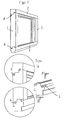
- FIG. 8 a possibility of fixing the position of the frame part 3 to the frame parts 2, 4 via L-shaped connecting elements 11 is shown.
- the connecting elements 11 are substantially attached to the frame parts 2, 4, that they are perpendicular to the longitudinal extent, at right angles to the outside of the mounted frame stock protrude to the longitudinal extent and form a stop for the frame part 3.
- the frame part 3 is provided with corresponding receptacles 21 for these protruding parts of the connecting elements 11 which extend parallel to the longitudinal extent of the frame part 3.
- the profile shape of the frame parts 2, 3 and 4 allows a precise insertion and movement of the frame part 3 along the longitudinal extent of the frame parts 2, 4 until the connecting elements 11 come into contact with the receptacles 21.
- the attachment can be optimized via screw connections, which is shown in Fig. 8 via corresponding openings.
- the screwing can be made possible via a machine thread in the connecting elements 11 and be performed from the inside of the frame stock.
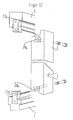
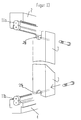
- FIGS. 12 and 13 respectively show a dovetail-shaped formation of connecting elements 11a, and an 8-shaped embodiment of connecting element 11b (Rampa sleeve).
- the fastening elements 11a, 11b are fastened to the frame parts 2, 4 substantially at right angles to the longitudinal extent of the frame parts 2, 4 via a suitable fastening means, for example a riveting or screw connection.
- Recesses 21a, 21b are incorporated on the frame part 3, substantially parallel to the longitudinal extent of the frame part 3 from the front side of the frame part 3.
- the receptacles 21a, 21b in the frame part 3 correspond in their cross-sectional shape to the part of the connecting elements 11a, 11b projecting from the frame plane.
- a change in position along the direction of the frame parts 2, 4 can be achieved either by a certain oversize and resulting compression of the part of the connecting elements 11a, 11b projecting from the frame plane relative to the receptacles 21a, 21b assigned to it, but it is also possible to to use additional fasteners, as shown in FIGS. 12 and 13.
- FIGS. 9, 10 and 11 illustrate the method according to the invention as follows.
- FIG. 9 shows a frame stock to be exchanged, in which only the frame parts bear the same reference numerals in order to simplify the illustration.
- a frame stock is usually surrounded by a masonry, so that the exact outer dimensions of the frame stick from the outside are not readily apparent.
- first spy holes 12 are introduced into the exchanged frame stock, whereupon standard profiles can be cut to size for the new frame stock.
- bores 13 and grooves 14 are preferably introduced into the new frame stock 1 (FIG. 10).
- the old window can be removed without damaging the surrounding masonry, for example by cutting and breaking.
- the lower frame part 4 of the new frame stock 1 (FIG. 11) is inserted into the resulting recess in the masonry and fixed, for example screwed.
- the upper frame part 2 is inserted into the also resulting from the removal of the old frame stock recess in the masonry, where it is not completely fixed to the masonry is only secured against falling.
- FIG. 11 the fastening elements 6 and the receptacles 16 according to the exemplary embodiment of FIGS. 2, 3a, 3b and 3c are shown by way of example.
- the mating surfaces of the connecting elements can be glued supportive - usually in wooden frame sticks, but the connecting element can also be screwed - typically plastic or light metal frame sticks.
- the lateral frame parts 3, 5 and the upper frame part 2 are fixed to the masonry, i. firmly connected to him, for example by dowels or construction screws, and it is through the holes 13 (Fig. 10) introduced a suitable seal, for example, sealing foam.
- a suitable seal for example, sealing foam.
- the sealing foam can be evenly distributed along the grooves 14 (FIG. 10) around the newly inserted frame stock 1, whereby an optimal seal can be achieved.
Abstract
Description
Die Erfindung betrifft allgemein ein Verfahren zum Montieren eines Rahmenstocks für Wandelemente. Unter Wandelement wird hauptsächlich ein Fenster oder eine Tür verstanden, die Erfindung ist aber ebenfalls auf Paneelsegmente, zusammengesetzte Fassaden oder dergleichen anwendbar.The invention relates generally to a method of mounting a frame stock for wall elements. Under wall element is mainly a window or a door understood, but the invention is also applicable to panel segments, composite facades or the like.
Beim Austausch von renovierungsbedürftigen Wandelementen ist es üblicherweise erforderlich, dass das den Blendrahmen umgebenden Mauerwerk, d.h. Mauerputz o.ä., abgeschlagen werden muss, um den neuen Rahmenstock setzen zu können. Dieses Verfahren hat den offensichtlichen Nachteil, dass abgesehen von eventuellen Beschädigungen der Außenfassade eine erhebliche Menge an Schmutz und Baustaub für den wünschenswerterweise bewohnten Raum anfällt.When replacing wall elements requiring renovation, it is usually necessary that the masonry surrounding the frame, i. Wall plaster or the like, must be knocked off to put the new frame stick can. This method has the obvious disadvantage that, apart from possible damage to the external facade, a considerable amount of dirt and dust for the desirably inhabited space is obtained.
Ein etwas verbessertes Verfahren zum Austausch von renovierungsbedürftigen Grundelementen besteht darin, den alten Rahmenstock entlang des Mauerwerks heraus zu schneiden, so dass ein Rest des alten Rahmenstocks im Mauerwerk verbleibt, und dann in die dadurch entstandene Öffnung einen kleineren Rahmenstock hineinzusetzen. Dieses Verfahren hat den Nachteil, dass erstens mit einem kleineren Wandelement Vorlieb genommen werden muss, was bei Fenstern typischerweise eine Einbuße von bis zu 10% der ursprünglichen Fensterfläche und einen entsprechenden Lichtverlust ausmacht. Zweitens hat es den Nachteil, dass der in der Wand verbleibende Rest des alten Rahmenstocks noch für die weitere Verwendung voll funktionsfähig sein muss. Dies ist beim Austausch von renovierungsbedürftigen Wandelementen allerdings häufig nicht der Fall. In derartigen Fällen verwendete Rahmenstöcke können von der in Fig. 1, 1a und 1b dargestellten Art sein.A slightly improved way to replace basic elements in need of refurbishment is to cut out the old frame stock along the masonry so that a remnant of the old frame stock remains in the masonry, and then insert a smaller frame stock into the resulting opening. This method has the disadvantage that, firstly, a smaller wall element must be used, which typically amounts to a loss of up to 10% of the original window area and a corresponding loss of light in the case of windows. Second, has it has the disadvantage that the remaining in the wall rest of the old frame stock still needs to be fully functional for further use. However, this is often not the case when replacing renovation-requiring wall elements. Frame sticks used in such cases may be of the type illustrated in Figs. 1, 1a and 1b.
Verwandter Stand der Technik ist beispielsweise auch aus der
Aus der
Ferner beschreibt die
Des Weiteren zeigt die
Gegenüber diesem Stand der Technik ist es Aufgabe der Erfindung, ein Verfahren zum Montieren eines Rahmenstocks anzugeben, durch das der Ersatz eines Wandelements durch ein gleich großes Wandelement vereinfacht wird.Compared to this prior art, it is an object of the invention to provide a method for mounting a frame stock, by which the replacement of a wall element is simplified by a same size wall element.
Erfindungsgemäß wird diese Aufgabe gelöst durch ein Verfahren zum Montieren eines Rahmenstocks mit den Merkmalen von Anspruch 1.According to the invention, this object is achieved by a method for mounting a frame stock with the features of claim 1.
Die vorliegende Erfindung beruht auf dem Grundgedanken, Rahmenteile eines Rahmenstocks nicht von außen zusammen zu stecken, sondern einen Rahmenstock für ein Wandelement von der Innenseite zur Außenseite des Wandelements zu montieren. Es werden Verbindungselemente zum Fixieren mehrerer Rahmenteile in ihrer Lage relativ zueinander derart bereitgestellt, dass sie keine Behinderung gegen eine Relativbewegung der Rahmenteile zu der endgültigen Form des Rahmenstocks darstellen, und zugleich die einzelnen Rahmenteile des Rahmenstocks miteinander verbinden. Im Sinne der vorliegenden Anmeldung steht der Ausdruck "Mauerwerk" beispielhaft für die den Rahmenstock in seiner üblichen Einbausituation zumindest bereichsweise umgebende Materie. Auch feste Holz- oder Stahlfassaden, Glaswände o.ä. sind daher von dem Ausdruck Mauerwerk umfasst. Die vorliegende Erfindung stellt beträchtliche Vorteile bereit. So bleibt die Fläche eines auszutauschenden Wandelements nicht nur voll erhalten, sondern kann je nach Konstruktion des neuen Rahmenstocks relativ zum alten Rahmenstock auch vergrößert werden. Der Auf- und Abbau von Außengerüsten kann entfallen, da ein Arbeiten aus dem Inneren eines Gebäudes möglich ist, und in einem typischen Anwendungsfall ist überdies ein erneutes Verputzen des Mauerwerks und ein Austausch von Tapeten oder dergleichen nicht notwendig. Der Rahmenstock und das Verfahren gemäß der vorliegenden Erfindung führen also zu beträchtlichen Einsparungen bezüglich Zeit, Arbeit und Kosten.The present invention is based on the idea not to put together frame parts of a frame stock from the outside, but to mount a frame stick for a wall element from the inside to the outside of the wall element. There are provided fasteners for fixing a plurality of frame members in position relative to each other such that they do not interfere with relative movement of the frame members to the final shape of the frame stock and at the same time interconnect the individual frame members of the frame stock. For the purposes of the present application, the term "masonry" is an example of the material surrounding the frame stick in its usual installation situation at least in certain areas. Also solid wood or steel facades, glass walls or similar. are therefore covered by the term masonry. The present invention provides significant advantages. Thus, the surface of a wall element to be exchanged not only fully preserved, but can also be increased depending on the construction of the new frame stock relative to the old frame stock. The construction and dismantling of external scaffolding can be omitted because working from the inside of a building is possible, and in a typical application is also a re-plastering of the masonry and an exchange of Wallpaper or the like not necessary. The frame stick and method according to the present invention thus lead to considerable savings in terms of time, labor and costs.
Vorteilhafte Weiterbildungen der vorliegenden Erfindung sind im folgenden und in den Unteransprüchen angegeben.Advantageous developments of the present invention are given in the following and in the subclaims.
Es ist beispielsweise bevorzugt, dass im montierten Zustand des Rahmenstocks das oder die Verbindungselemente formschlüssig in entsprechenden Aufnahmen der durch das oder die Verbindungselemente in ihrer Lage zueinander fixierten Rahmenteile aufgenommen ist. Bei geeigneter Ausführung der Aufnahmen bietet diese Weiterbildung der Erfindung den Vorteil, dass eine Lagefixierung der Rahmenteile in den wesentlichen Richtungen automatisch bei der Montagebewegung von innen nach außen erzielt wird, ohne dass weitere Maßnahmen notwendig sind. Ergänzend kann hierbei eine kraftschlüssige Verbindung vorgesehen sein, um auch eine Lagefixierung gegen die Montagerichtung zu erzielen.It is preferred, for example, that in the mounted state of the frame stock, the one or more connection elements is positively received in corresponding receptacles of the one or more of the connecting elements in their position fixed to each other frame parts. With a suitable design of the recordings, this development of the invention offers the advantage that a positional fixation of the frame parts in the essential directions is automatically achieved during the assembly movement from the inside to the outside, without further measures being necessary. In addition, a frictional connection may be provided in this case, in order to achieve a positional fixation against the mounting direction.
Es ist vorgesehen, dass die Aufnahmen sich im Wesentlichen rechtwinklig zur Längserstreckung des unteren bzw oberen Rahmenteils und parallel zur Längserstreckung der zwei weiteren Rahmenteile befinden, allerdings an Seiten der Rahmenteile, die im montierten Zustand des Rahmenstocks die Außenseiten des Rahmenstocks sind. Auf dieses Weise kann ein klar definierter Anschlag bei der Montage der Rahmenteile bereitgestellt werden, der von dem umgebenden Mauerwerk unabhängig ist. Ein späterer Zugang zu den Verbindungselementen und somit eine zusätzliche Befestigungsmöglichkeit wird ebenfalls bereitgestellt.It is envisaged that the receptacles are substantially perpendicular to the longitudinal extent of the lower or upper frame part and parallel to the longitudinal extent of the two other frame parts, but on sides of the frame parts, which are the outer sides of the frame stock in the assembled state of the frame stock. In this way, a clearly defined stop can be provided during assembly of the frame parts, which is independent of the surrounding masonry. A later access to the connecting elements and thus an additional mounting option is also provided.
Solche zusätzlichen unterstützenden Befestigungsmöglichkeiten können über Verleimen, Verschrauben, Vernieten oder Verpressen der Verbindungselemente mit den jeweiligen Rahmenteilen, oder auch der Rahmenteile miteinander vorgesehen sein. Dies entspricht einer bevorzugten Weiterbildung der Erfindung.Such additional supportive fastening options can by gluing, screwing, riveting or pressing the connecting elements with the respective frame parts, or even the frame parts together be provided. This corresponds to a preferred embodiment of the invention.
Üblicherweise werden die Wandelemente, bei denen der Rahmenstock zur Anwendung kommt, rechteckig sein. Entsprechend ist vorgesehen, dass der Rahmenstock vier im montierten Zustand rechtwinklig angeordnete Rahmenteile aufweist. Eine solche Anordnung vereinfacht zudem den Montagevorgang.Usually, the wall elements in which the frame stock is used, be rectangular. Accordingly, it is provided that the frame stock has four in the assembled state arranged at right angles frame parts. Such an arrangement also simplifies the assembly process.
Der Rahmenstock kommt mit einem einzigen Verbindungselement zum Fixieren zweier Rahmenteile aus.The frame stock comes with a single connection element for fixing two frame parts.
Es hat sich bezüglich der Festigkeit des Rahmenstocks als besonders bevorzugt herausgestellt, Verbindungselemente mit einem schwalbenschwanzförmigen oder 8-förmigen Querschnitt zu verwenden.It has been found to be particularly preferred with respect to the strength of the frame stock to use connecting elements with a dovetail-shaped or 8-shaped cross-section.
Um die Abdichtung des Rahmenstocks gegenüber dem umgebenden Mauerwerk zu optimieren, und den Abdichtvorgang weitestgehend zu vereinfachen, ist erfindungsgemäß des Weiteren vorgesehen, dass der Rahmenstock in den Rahmenteilen Bohrungen und/oder Nuten zum Einbringen eines Abdichtmittels aufweist.In order to optimize the sealing of the frame stock with respect to the surrounding masonry, and to simplify the sealing process as far as possible, it is further provided according to the invention that the frame stock has bores and / or grooves for introducing a sealing means in the frame parts.
Das erfindungsgemäße Verfahren umfasst gemäß einer Weiterbildung, dass Schritte (d) und (e) für jedes der zwei weiteren Rahmenteile nacheinander durchgeführt werden, z.B. wenn sich aufgrund von Toleranzen in den Einbaumaßen oder Rückständen des alten Rahmenstocks samt vorher eventuell vorhandenen Abdichtmittel ein Kraftaufwand bei der Montage ergeben sollte, der das zeitgleiche Einbringen der zwei weiteren Rahmenteile zwischen das untere und das obere Rahmenteil schwierig macht.According to a development, the method according to the invention comprises that steps (d) and (e) are carried out successively for each of the two further frame parts, e.g. if due to tolerances in the installation dimensions or residues of the old frame stock together with any previously existing sealing means should result in a force during assembly, which makes the simultaneous introduction of the two other frame parts between the lower and the upper frame part difficult.
Die Montage ist weiter vereinfacht, wenn der Kraftaufwand zum Einbringen des oder der weiteren Rahmenteile zwischen das untere und das obere Rahmenteil graduell erhöht wird, weswegen nach einer Weiterbildung des erfindungsgemäßen Verfahrens vorgesehen ist, dass die weiteren Rahmenteile im mittleren Bereich der Längserstreckung des unteren und/oder des oberen Rahmenteils eingebracht werden.The assembly is further simplified if the force required for introducing the or the other frame parts between the lower and the upper frame part is gradually increased, Therefore, according to a development of the method according to the invention, provision is made for the further frame parts to be introduced in the middle region of the longitudinal extension of the lower and / or the upper frame part.
Es ist grundsätzlich möglich, nur das untere Rahmenteil fest an dem Mauerwerk zu fixieren, und nachfolgend den Rahmen in seiner Grundform zusammenzusetzen. Bevorzugt ist es, nach dem Zusammensetzen des erfindungsgemäßen Rahmenstocks zu seiner endgültigen Form auch das obere Rahmenteil und/oder die zwei weiteren Rahmenteile an dem umgebenden Mauerwerk zu fixieren, damit die Qualität der Abdichtung und der Passgenauigkeit erhöht wird.It is basically possible to fix only the lower frame part fixed to the masonry, and subsequently assemble the frame in its basic form. It is preferred to fix after assembling the frame stick according to the invention to its final shape and the upper frame part and / or the two other frame parts to the surrounding masonry, so that the quality of the seal and the fit accuracy is increased.
Bevorzugte Ausführungsformen der vorliegenden Erfindung werden nachfolgend unter Bezugnahme auf die beigefügten Zeichnungen näher erläutert. In den Zeichnungen zeigt:
- Fig. 1
- Einen Rahmenstock gemäß dem Stand der Technik;
- Fig. 2
- einen Rahmenstock zur Verwendung mit der vorliegenden Erfindung;
- Fig. 3a-3c
- Einzelheiten des Rahmenstocks gemäß der Fig. 2;
- Fig. 4
- einen weiteren Rahmenstock zur Verwendung mit der vorliegenden Erfindung;
- Fig. 5
- einen wiederum weiteren Rahmenstock, aus der besonders gut Einzelheiten des erfindungsgemäßen Montageverfahrens hervorgehen;
- Fig. 6, 7 und 8
- weitere Ausführungsformen des Rahmenstocks;
- Fig. 9, 10
und 11 - das erfindungsgemäße Montageverfahren z.B. mit dem Rahmenstock nach Fig. 2;
- Fig. 12
und 13 - einen wiederum weiteren Rahmenstock im Detail.
- Fig. 1
- A frame stick according to the prior art;
- Fig. 2
- a frame stick for use with the present invention;
- Fig. 3a-3c
- Details of the frame stock according to FIG. 2;
- Fig. 4
- another frame stock for use with the present invention;
- Fig. 5
- in turn, another frame stock, emerge particularly well details of the assembly method according to the invention;
- FIGS. 6, 7 and 8
- further embodiments of the frame stock;
- FIGS. 9, 10 and 11
- the assembly method according to the invention, for example, with the frame stick of Fig. 2;
- FIGS. 12 and 13
- a turn another frame stick in detail.
Wie aus Fig. 2 ersichtlich ist, besteht der Rahmenstock 1 aus einzelnen Rahmenteilen 2, 3, 4, 5, die üblicherweise rechtwinklig zueinander angeordnet sind. Obgleich der Rahmenstock in sämtlichen dargestellten Ausführungsbeispielen als vier Rahmenteile umfassend und von rechteckiger Grundform dargestellt ist, sind auch rechteckige Formen mit mehr als vier Rahmenteilen und andere Polygonformen denkbar, beispielsweise Sechsecke oder Achtecke.As is apparent from Fig. 2, the frame stock 1 consists of
Der Rahmenstock 1 in Fig. 2 umfasst Befestigungselemente 6, die eine Lagefixierung der Rahmenteile 2, 3, 4, 5 relativ zueinander erlauben. Hierzu ist vorgesehen, dass an den oberen und unteren Rahmenteilen 2, 4, Verbindungselemente 6 von der Rahmenebene vorstehen, wie auch aus den Fig. 3a, 3b und 3c besser hervorgeht. Diese Verbindungselemente 6 können dabei einstückig mit dem Rahmenteil ausgeführt sein, was sich bei Kunststoffwandelementen besonders eignet, oder als separate Teile in entsprechende Ausnehmungen, beispielsweise gefräste Nuten eingebracht sein. Letztere Ausführungsform eignet sich besonders für Holzwandelemente, und der Formschluss durch das Einbringen der Verbindungselemente 6 in entsprechende Ausfräsungen kann durch eine Einleimung unterstützt sein.The frame stock 1 in Fig. 2 comprises
Weitere Verbindungsarten der Rahmenteile 2, 3, 4, 5 mit den Verbindungselementen 6 ist z. B. Verschrauben, Vernieten, oder Verpressen, wie aus der nachfolgenden Beschreibung hervorgeht.Other types of connection of the
Die Verbindungselemente 6 sind in Fig. 2 in einer Querschnittform als Schwalbenschwanz dargestellt, können aber in einer Vielzahl von unterschiedlichen Formen ausgeführt sein, wobei über diese Verbindungselemente ebenfalls Anschlagflächen vorgesehen sein können, die eine Bewegung der parallelen Rahmenteile 3, 5 über das Ende der Rahmenteile 2, 4 hinaus verhindern.The connecting
Während Fig. 2 und 3a, 3b, 3c eine mehrteilige Ausführungsform von Rahmenteilen 2, 3, 4, 5 und Verbindungselemente 6 darstellen, ist in dem Ausführungsbeispiel gemäß Fig. 4 eine einstückige Ausbildung dargestellt. Bei dieser einstückigen Ausführungsform weisen die oberen und unteren Rahmenteile 2, 4 stegartige Vorsprünge 7 als Verbindungselement auf. Eine Fixierung des Rahmenteils 3 and den Rahmenteilen 2, 4 in Fig. 4 kann erzielt werden, indem das Rahmenteil 3 passgenau in die Lücke zwischen die Rahmenteile 2, 4 eingebracht und dann in Richtung der Pfeile in Fig. 4 entlang der Längserstreckung der Rahmenteile 2, 4 bewegt wird. Hierbei werden die stegartigen Verbindungselemente 7 in entsprechend geformten Aufnahmen 17 aufgenommen, wo sie über Formschluss und ggf. zusätzlich über Kraftschluss eine Lagefixierung zwischen den Rahmenteilen 2, 4 einerseits und dem Rahmenteil 3 andererseits vorsehen. Der Formschluss kann durch eine gewisses Übermaß der Verbindungselemente 7 relativ zu den Aufnahmen 17 erzielt werden, so dass über Verpressen eine sichere Verbindung bereitgestellt wird, oder gegebenenfalls durch Verleimen o.ä..While FIGS. 2 and 3a, 3b, 3c represent a multi-part embodiment of
Fig. 5 zeigt ein weiteres Beispiel, bei dem sowohl die Verbindungselemente 8 der Rahmenteile 2, 4 als auch die entsprechenden Aufnahmen 18 an dem Rahmenteil 3 jeweils zweiteilig ausgeführt sind. Bei den Rahmenteilen 2, 4 werden Einschublaschen 8' in Pfeilrichtung in entsprechende Ausnehmungen an den Rahmenteilen eingebracht und dort befestigt. Entsprechend wird mit Rahmenteil 3 verfahren, in das Einschublaschen 8' mit Ausnehmungen 18 eingebracht und befestigt werden. Die weitere Vorgehensweise entspricht der Darstellung in Fig. 4.FIG. 5 shows a further example in which both the connecting
In Fig. 6 ist ein Ausführungsbeispiel dargestellt, in dem die Verbindungselemente 9 eine 8-Form aufweisen, und im Rahmenteil 3 Ausnehmungen eingearbeitet sind, die in ihrem Querschnitt einem Segment der Form "8" entsprechen.In Fig. 6, an embodiment is shown, in which the connecting
In Fig. 7 sind Verbindungselemente einer weiteren Querschnittsform dargestellt und in der Fig. mit 10 bezeichnet. Die Verbindungselemente 10 der Fig. 7 weisen im Querschnitt eine Doppel-T-Form auf, so dass sie mit dem einen Querbalken des "T" in entsprechende Ausnehmungen der Rahmenteile 2, 4 eingesetzt werden können, und mit der Hälfte des Längsbalken sowie dem zweiten Querbalken des "T" über die Rahmenebenen vorstehen. Im Rahmenteil 3 sind entsprechend T-förmige Ausnehmungen 20 vorgesehen, die zu dem über die Rahmenebene vorstehende Teil der Verbindungselemente 10 passen. Die Fixierung des Rahmenteils 3 an den Rahmenteilen 2, 4 erfolgt wie bei den vorhergehenden Ausführungsformen.In Fig. 7 connecting elements of a further cross-sectional shape are shown and designated in the Fig. 10. The connecting
Die Länge der Befestigungselemente 7, 8, 9 (entsprechend Fig. 4, 5, 6) sowie der Befestigungselemente 10 (Fig. 9) ist typischerweise gleich oder kleiner als die Breite des Rahmenelements 3, so dass im montierten Zustand des Rahmenstocks die Befestigungselemente von der Innenseite des Rahmenstocks 1 aus einerseits nicht sichtbar sind, und andererseits keine Behinderung für die Montage eines Fensterflügels oder dergleichen darstellen.The length of the
In Fig. 8 ist eine Möglichkeit der Lagefixierung von Rahmenteil 3 an den Rahmenteilen 2, 4 über L-förmige Verbindungselemente 11 dargestellt. Die Verbindungselemente 11 sind dabei im Wesentlichen derart an den Rahmenteilen 2, 4 befestigt, dass sie rechtwinklig zur Längserstreckung liegen, an der Außenseite des montierten Rahmenstocks rechtwinklig zur Längserstreckung vorstehen und einen Anschlag für das Rahmenteil 3 bilden. Das Rahmenteil 3 ist mit entsprechenden Aufnahmen 21 für diese vorstehenden Teile der Verbindungselemente 11 versehen, die parallel zur Längserstreckung des Rahmenteils 3 verlaufen.In Fig. 8, a possibility of fixing the position of the
Wie in den anderen Ausführungsformen ermöglicht die Profilform der Rahmenteile 2, 3 und 4 ein passgenaues Einsetzen und Bewegen des Rahmenteils 3 entlang der Längserstreckung der Rahmenteile 2, 4, bis die Verbindungselemente 11 in den Aufnahmen 21 zur Anlage kommen. Die Befestigung kann hierbei über Verschraubungen optimiert werden, was in Fig. 8 über entsprechende Öffnungen dargestellt ist. Die Verschraubung kann über ein Maschinengewinde in den Verbindungselementen 11 ermöglicht und von der Innenseite des Rahmenstocks aus durchgeführt werden.As in the other embodiments, the profile shape of the
Fig. 12 und 13 zeigen entsprechend eine schwalbenschwanzförmige Ausbildung von Verbindungselementen 11a, bzw. eine 8-förmige Ausbildung von Verbindungselement 11b (Rampa-Muffe).FIGS. 12 and 13 respectively show a dovetail-shaped formation of connecting elements 11a, and an 8-shaped embodiment of connecting
Die Befestigungselemente 11a, 11b sind im Wesentlichen rechtwinklig zur Längserstreckung der Rahmenteile 2, 4 über ein geeignetes Befestigungsmittel - beispielsweise eine Vernietung oder Verschraubung - an den Rahmenteilen 2, 4 befestigt. Am Rahmenteil 3 sind Ausnehmungen 21a, 21b eingearbeitet, von der Stirnseite des Rahmenteils 3 aus im Wesentlichen parallel zur Längserstreckung des Rahmenteils 3. Die Aufnahmen 21a, 21b im Rahmenteil 3 entsprechen in ihrer Querschnittsform dem vom der Rahmenebene vorstehende Teil der Verbindungselemente 11a, 11b.The
Des Weiteren weisen sie von der Stirnseite des Rahmenteils 3 aus betrachtet eine Hinterschneidung auf, was auf vorteilhafte Weise sicherstellt, dass allein aufgrund des Formschlusses zwischen den Verbindungselementen 11a, 11b und den ihnen zugeordneten Aufnahmen 21a, 21b und dem entsprechenden Formschluss des in die Rahmenteile 2, 4 eingearbeiteten Teils der Verbindungselemente 11a, 11b eine Fixierung einer Lageveränderung zwischen Rahmenteilen 2, 4 und Rahmenteil 3 in Richtung der Längserstreckung des Rahmenteils 3 gesichert ist. Eine Lageveränderung entlang der Richtung der Rahmenteile 2, 4 kann entweder durch ein gewisses Übermaß und ein sich ergebendes Verpressen des von der Rahmenebene vorstehenden Teils der Verbindungselemente 11a, 11b relativ zu den ihnen zugeordneten Aufnahmen 21a, 21b erzielt werden, es ist jedoch ebenfalls möglich, zusätzliche Befestigungselemente zu verwenden, wie dies auch in den Fig. 12 und 13 dargestellt ist.Furthermore, they have, viewed from the front side of the
Da Maschinenschrauben im technischen Gebiet der vorliegenden Erfindung üblicherweise ohne weiteres vorhanden sind, hat sich eine handelsübliche Verschraubung als besonders geeignet herausgestellt. Zu diesem Zweck ist in den Verbindungselementen 11a, 11b ein Gewinde mit einer Tiefe vorgesehen, die einen sicheren Halt gewährleistet.Since machine screws are usually readily available in the technical field of the present invention, a commercially available screw has been found to be particularly suitable. For this purpose, a thread with a depth is provided in the connecting
Die Fig. 9, 10 und 11 verdeutlichen das erfindungsgemäße Verfahren wie folgt.FIGS. 9, 10 and 11 illustrate the method according to the invention as follows.
In Fig. 9 ist ein auszutauschender Rahmenstock dargestellt, bei dem lediglich zur Vereinfachung der Darstellung die Rahmenteile die gleichen Bezugszeichen tragen. Ein derartiger Rahmenstock ist üblicherweise von einem Mauerwerk umgeben, so dass die genauen Außenmaße des Rahmenstocks von Außen nicht ohne weiteres ersichtlich sind. Um diese Außenmaße festzustellen, werden zunächst Spionbohrungen 12 in den auszutauschenden Rahmenstock eingebracht, woraufhin für den neuen Rahmenstock Standardprofile auf Maß abgelängt werden können. Ebenfalls werden bevorzugt Bohrungen 13 und Nuten 14 in den neuen Rahmenstock 1 eingebracht (Fig. 10).FIG. 9 shows a frame stock to be exchanged, in which only the frame parts bear the same reference numerals in order to simplify the illustration. Such a frame stock is usually surrounded by a masonry, so that the exact outer dimensions of the frame stick from the outside are not readily apparent. To determine these outer dimensions, first spy holes 12 are introduced into the exchanged frame stock, whereupon standard profiles can be cut to size for the new frame stock. Likewise, bores 13 and
Anschließend kann dann der alte Fensterstock ohne Beschädigung des umgebenden Mauerwerks herausgenommen werden, beispielsweise durch Einschneiden und Ausbrechen. Das untere Rahmenteil 4 des neuen Rahmenstocks 1 (Fig. 11) wird in die sich somit ergebende Aussparung im Mauerwerk eingesetzt und fixiert, beispielsweise verschraubt. Danach wird das obere Rahmenteil 2 in die sich ebenfalls durch das Entfernen des alten Rahmenstocks ergebende Aussparung im Mauerwerk eingeführt, wobei es nicht vollständig am Mauerwerk fixiert wird sonder lediglich gegen Herunterfallen gesichert wird.Then then the old window can be removed without damaging the surrounding masonry, for example by cutting and breaking. The
Schließlich werden die beiden seitlichen Rahmenteile 3, 5 im Bereich der Fenstermitte eingeführt (Fig. 11) und solange nach außen geschoben, bis die Verbindungselemente in die entsprechenden Ausnehmungen der Rahmenteile 3, 5 eingreifen und somit die einzelnen Rahmenteile 2, 3, 4, 5 zu einem kompletten Rahmenstock 1 zusammengefügt sind. In der Fig. 11 sind beispielhaft die Befestigungselemente 6 und die Aufnahmen 16 gemäß dem Ausführungsbeispiel der Fig. 2, 3a, 3b und 3c dargestellt.Finally, the two
Die Passflächen der Verbindungselemente können unterstützend verleimt sein - üblicherweise bei Holzrahmenstöcken, die Verbindungselement können aber auch verschraubt sein - typischerweise bei Kunststoff- oder Leichtmetallrahmenstöcken.The mating surfaces of the connecting elements can be glued supportive - usually in wooden frame sticks, but the connecting element can also be screwed - typically plastic or light metal frame sticks.
Hiernach werden auch die seitlichen Rahmenteile 3, 5 und das obere Rahmenteil 2 an dem Mauerwerk fixiert, d.h. fest mit ihm verbunden, beispielsweise durch Dübel oder Bauschrauben, und es wird durch die Bohrungen 13 (Fig. 10) eine geeignete Abdichtung eingebracht, beispielsweise Dichtungsschaum. Der Dichtungsschaum kann sich entlang der Nuten 14 (Fig. 10) gleichmäßig um den neu eingebrachten Rahmenstock 1 verteilen, wodurch eine optimale Abdichtung erzielbar ist.Thereafter, the
Claims (8)
- Method for mounting a blind casing constructed from several frame portions in masonry or the like, with the following steps:(a) introducing a lower frame portion (4) into the masonry and fixing this frame portion to the masonry, the lower frame portion being provided with a connecting element;(b) introducing an upper frame portion (2) into the masonry, the upper frame portion being located opposite the first frame portion in the mounted state of the blind casing and being provided with a connecting element;(c) preventing the upper frame portion (2) from dropping down;(d) introducing two further frame portions (3, 5) between the lower (4) and upper (2) frame portions;(e) moving the further frame portions (3, 5) along the longitudinal extent of the upper (4) and/or lower (2) frame portions until the connecting elements of the lower and/or upper frame portions are engaged with receptacles in the further frame portions (3, 5).
- Method according to claim 1, characterised in that steps (d) and (e) are performed several times one after the other for each of the two further frame portions (3, 5).
- Method according to claim 1 or 2, characterised in that in step (d) the two further frame portions (3, 5) are introduced between the lower (4) and upper (2) frame portions in the central region of the longitudinal extent of the lower and/or upper frame portion.
- Method according to one or more of claims 1 to 3, characterised in that in a step(f) the upper frame portion and the two further frame portions are fixed to the masonry.
- Method according to one or more of claims 1 to 4, characterised in that the connecting elements of the lower and/or upper frame portions are glued, bolted, riveted or pressed to the two further frame portions.
- Method according to one or more of claims 1 to 5, characterised in that in a further step(g) through holes and/or grooves in at least one of the frame portions, sealing means are introduced between the blind casing and the masonry.
- Method according to one or more of claims 1 to 6, characterised in that the connecting elements have a dovetailed or figure-of-eight cross-section.
- Method according to one or more of claims 1 to 7, characterised in that the receptacles (21, 21a, 21b) are located substantially at right angles to the longitudinal extent of the lower and/or upper frame portions (2, 4) and parallel to the longitudinal extent of the two further frame portions (3, 5), on sides of the frame portions which are the outer sides of the blind casing in the mounted state of the blind casing (1).
Priority Applications (2)
| Application Number | Priority Date | Filing Date | Title |
|---|---|---|---|
| DE20022155U DE20022155U1 (en) | 1999-10-26 | 2000-10-26 | Frame stick for wall elements |
| DE20107229U DE20107229U1 (en) | 2000-10-26 | 2001-04-26 | Connecting element for a frame stick of a window or a door |
Applications Claiming Priority (2)
| Application Number | Priority Date | Filing Date | Title |
|---|---|---|---|
| DE19951485 | 1999-10-26 | ||
| DE19951485A DE19951485A1 (en) | 1999-10-26 | 1999-10-26 | Frame for windows or doors |
Publications (3)
| Publication Number | Publication Date |
|---|---|
| EP1096096A2 EP1096096A2 (en) | 2001-05-02 |
| EP1096096A3 EP1096096A3 (en) | 2002-02-13 |
| EP1096096B1 true EP1096096B1 (en) | 2007-09-05 |
Family
ID=7926893
Family Applications (1)
| Application Number | Title | Priority Date | Filing Date |
|---|---|---|---|
| EP00123312A Expired - Lifetime EP1096096B1 (en) | 1999-10-26 | 2000-10-26 | Method of mounting a wall element |
Country Status (3)
| Country | Link |
|---|---|
| EP (1) | EP1096096B1 (en) |
| AT (1) | ATE372440T1 (en) |
| DE (2) | DE19951485A1 (en) |
Families Citing this family (3)
| Publication number | Priority date | Publication date | Assignee | Title |
|---|---|---|---|---|
| DE102006003968A1 (en) * | 2006-01-26 | 2007-08-02 | Mea Bausysteme Gmbh | Zargenfenster |
| DE202009002175U1 (en) * | 2009-02-16 | 2009-06-18 | Optiwin Gmbh | Corner piece for window frames |
| FR3054419B1 (en) * | 2016-07-26 | 2018-12-07 | Inovame | FURNITURE BOX |
Family Cites Families (14)
| Publication number | Priority date | Publication date | Assignee | Title |
|---|---|---|---|---|
| DE816011C (en) * | 1949-08-31 | 1952-01-07 | Friedrich Woerner | Method for mortising components |
| DE862660C (en) * | 1951-01-30 | 1953-01-12 | Adolf Von Minden | Corner connection for wooden components, especially for windows |
| FI37123A (en) * | 1966-04-01 | 1967-08-10 | Saastamoinen Oy H | Corner connection of window or door frames |
| NL6614322A (en) * | 1966-10-11 | 1968-04-16 | ||
| GB1243662A (en) * | 1968-01-22 | 1971-08-25 | Rotax Ltd | Linear motion bearings |
| DE2412268A1 (en) * | 1974-03-14 | 1975-09-18 | Leben & Co | Restoration components for old window frames - are joined to trimmed old frame which is cut back |
| US4265052A (en) * | 1979-08-17 | 1981-05-05 | Johnson Earl L | Storm window construction |
| AT377643B (en) * | 1981-07-01 | 1985-04-10 | Kistler Instrumente Ag | METHOD FOR PRODUCING MOLDED PIECES FROM SEMICONDUCTOR CRYSTALS, IN PARTICULAR PRESSURE RECEIVER ELEMENTS |
| NL189314C (en) * | 1982-03-03 | 1993-03-01 | Hendrikus Gerhardus Varwijk | FRAMEWORK, SUCH AS A FRAME, BUILT-UP FROM PRE-MANUFACTURED BEAMS TO BE SHORTEN, AND BEAMS FOR SUCH FRAMEWORK. |
| US4457110A (en) * | 1982-03-11 | 1984-07-03 | Beirnes James R | Window conversion assembly |
| IE56623B1 (en) * | 1984-06-16 | 1991-10-09 | Fairmitre Ltd | Improvements in window-frames |
| JP2820529B2 (en) | 1989-02-09 | 1998-11-05 | ソシエテ、カセス | Frame and frame mold assembly equipment |
| DE9306791U1 (en) * | 1993-05-05 | 1993-09-30 | Gewe Selecta Fenster Und Rolla | Frames, in particular window and casement frames for windows |
| US5737890A (en) * | 1995-10-18 | 1998-04-14 | Heyden; Marsha Vander | Frame assembly |
-
1999
- 1999-10-26 DE DE19951485A patent/DE19951485A1/en not_active Withdrawn
-
2000
- 2000-10-26 DE DE50014624T patent/DE50014624D1/en not_active Expired - Lifetime
- 2000-10-26 EP EP00123312A patent/EP1096096B1/en not_active Expired - Lifetime
- 2000-10-26 AT AT00123312T patent/ATE372440T1/en active
Also Published As
| Publication number | Publication date |
|---|---|
| EP1096096A3 (en) | 2002-02-13 |
| DE50014624D1 (en) | 2007-10-18 |
| EP1096096A2 (en) | 2001-05-02 |
| DE19951485A1 (en) | 2001-06-21 |
| ATE372440T1 (en) | 2007-09-15 |
Similar Documents
| Publication | Publication Date | Title |
|---|---|---|
| EP0136431A2 (en) | Sectional frame | |
| EP0152110A2 (en) | Edge cover strip for a glass pane, in particular for a door wing made completely of glass | |
| DE19900095C1 (en) | Frame for opening in building wall has connected shells with adjusting screw and anchor | |
| DE10118791A1 (en) | Connector for linking mitered hollow profiles has arms at right-angles and grooves which allow adhesive injected through bores in top of profile to spread through connector, one of which has sloping wall | |
| EP1785535A1 (en) | Connecting device and method for connecting a wooden beam with a wooden supporting structure | |
| DE4437816A1 (en) | Process and apparatus for connecting plastic profiles | |
| EP1096096B1 (en) | Method of mounting a wall element | |
| DE19539862A1 (en) | Hollow profiles corner connection, especially for window and door frames | |
| EP0906998B1 (en) | Face plate mounting arrangement | |
| EP2128372B1 (en) | Plastic window or door and method for production of same | |
| DE102007029647B4 (en) | Mounting arrangement and method of mounting a support plate in a through hole between walls | |
| DE19719013C2 (en) | With a wall bracket, cross-sectionally U-shaped holding profile for a partition | |
| EP0371237B1 (en) | Kit for a door case | |
| AT501571B1 (en) | COMPOSITE PROFILE | |
| DE102014100688A1 (en) | profile connector | |
| DE8322475U1 (en) | Frame made of profile rods | |
| DE4307153C2 (en) | Method and device for producing an aluminum hollow profile corner connection for doors and windows | |
| DE2507393A1 (en) | Roller sliding door and window sectioned frame - has H-sectioned components with screws between clamping battens on roller carriers | |
| DE3147060A1 (en) | Frame profile | |
| DE102007005290B4 (en) | audit device | |
| EP0253312A2 (en) | Cabin construction | |
| EP0987396A2 (en) | Cladding for windows or doors | |
| DE19704957C1 (en) | Fixed staircase with side-pieces and steps | |
| EP1590124A1 (en) | Window or door | |
| DE1953104A1 (en) | Process for the production of composite profiles and composite profile for carrying out the process and corner connection |
Legal Events
| Date | Code | Title | Description |
|---|---|---|---|
| PUAI | Public reference made under article 153(3) epc to a published international application that has entered the european phase |
Free format text: ORIGINAL CODE: 0009012 |
|
| AK | Designated contracting states |
Kind code of ref document: A2 Designated state(s): AT BE CH CY DE DK ES FI FR GB GR IE IT LI LU MC NL PT SE |
|
| AX | Request for extension of the european patent |
Free format text: AL;LT;LV;MK;RO;SI |
|
| PUAL | Search report despatched |
Free format text: ORIGINAL CODE: 0009013 |
|
| AK | Designated contracting states |
Kind code of ref document: A3 Designated state(s): AT BE CH CY DE DK ES FI FR GB GR IE IT LI LU MC NL PT SE |
|
| AX | Request for extension of the european patent |
Free format text: AL;LT;LV;MK;RO;SI |
|
| 17P | Request for examination filed |
Effective date: 20020730 |
|
| AKX | Designation fees paid |
Free format text: AT BE CH CY DE DK ES FI FR GB GR IE IT LI LU MC NL PT SE |
|
| 17Q | First examination report despatched |
Effective date: 20060404 |
|
| GRAP | Despatch of communication of intention to grant a patent |
Free format text: ORIGINAL CODE: EPIDOSNIGR1 |
|
| RTI1 | Title (correction) |
Free format text: METHOD OF MOUNTING A WALL ELEMENT |
|
| GRAS | Grant fee paid |
Free format text: ORIGINAL CODE: EPIDOSNIGR3 |
|
| GRAA | (expected) grant |
Free format text: ORIGINAL CODE: 0009210 |
|
| AK | Designated contracting states |
Kind code of ref document: B1 Designated state(s): AT BE CH CY DE DK ES FI FR GB GR IE IT LI LU MC NL PT SE |
|
| REG | Reference to a national code |
Ref country code: GB Ref legal event code: FG4D Free format text: NOT ENGLISH |
|
| REG | Reference to a national code |
Ref country code: CH Ref legal event code: EP |
|
| REF | Corresponds to: |
Ref document number: 50014624 Country of ref document: DE Date of ref document: 20071018 Kind code of ref document: P |
|
| REG | Reference to a national code |
Ref country code: IE Ref legal event code: FG4D Free format text: LANGUAGE OF EP DOCUMENT: GERMAN |
|
| PG25 | Lapsed in a contracting state [announced via postgrant information from national office to epo] |
Ref country code: FI Free format text: LAPSE BECAUSE OF FAILURE TO SUBMIT A TRANSLATION OF THE DESCRIPTION OR TO PAY THE FEE WITHIN THE PRESCRIBED TIME-LIMIT Effective date: 20070905 Ref country code: ES Free format text: LAPSE BECAUSE OF FAILURE TO SUBMIT A TRANSLATION OF THE DESCRIPTION OR TO PAY THE FEE WITHIN THE PRESCRIBED TIME-LIMIT Effective date: 20071216 |
|
| NLV1 | Nl: lapsed or annulled due to failure to fulfill the requirements of art. 29p and 29m of the patents act | ||
| GBV | Gb: ep patent (uk) treated as always having been void in accordance with gb section 77(7)/1977 [no translation filed] | ||
| REG | Reference to a national code |
Ref country code: IE Ref legal event code: FD4D |
|
| BERE | Be: lapsed |
Owner name: BUCHNER, KARL Effective date: 20071031 |
|
| PG25 | Lapsed in a contracting state [announced via postgrant information from national office to epo] |
Ref country code: GR Free format text: LAPSE BECAUSE OF FAILURE TO SUBMIT A TRANSLATION OF THE DESCRIPTION OR TO PAY THE FEE WITHIN THE PRESCRIBED TIME-LIMIT Effective date: 20071206 Ref country code: NL Free format text: LAPSE BECAUSE OF FAILURE TO SUBMIT A TRANSLATION OF THE DESCRIPTION OR TO PAY THE FEE WITHIN THE PRESCRIBED TIME-LIMIT Effective date: 20070905 |
|
| EN | Fr: translation not filed | ||
| PG25 | Lapsed in a contracting state [announced via postgrant information from national office to epo] |
Ref country code: PT Free format text: LAPSE BECAUSE OF FAILURE TO SUBMIT A TRANSLATION OF THE DESCRIPTION OR TO PAY THE FEE WITHIN THE PRESCRIBED TIME-LIMIT Effective date: 20080206 Ref country code: MC Free format text: LAPSE BECAUSE OF NON-PAYMENT OF DUE FEES Effective date: 20071031 Ref country code: IE Free format text: LAPSE BECAUSE OF FAILURE TO SUBMIT A TRANSLATION OF THE DESCRIPTION OR TO PAY THE FEE WITHIN THE PRESCRIBED TIME-LIMIT Effective date: 20070905 Ref country code: GB Free format text: LAPSE BECAUSE OF FAILURE TO SUBMIT A TRANSLATION OF THE DESCRIPTION OR TO PAY THE FEE WITHIN THE PRESCRIBED TIME-LIMIT Effective date: 20070905 |
|
| REG | Reference to a national code |
Ref country code: CH Ref legal event code: PL |
|
| PG25 | Lapsed in a contracting state [announced via postgrant information from national office to epo] |
Ref country code: SE Free format text: LAPSE BECAUSE OF FAILURE TO SUBMIT A TRANSLATION OF THE DESCRIPTION OR TO PAY THE FEE WITHIN THE PRESCRIBED TIME-LIMIT Effective date: 20071205 |
|
| PLBE | No opposition filed within time limit |
Free format text: ORIGINAL CODE: 0009261 |
|
| STAA | Information on the status of an ep patent application or granted ep patent |
Free format text: STATUS: NO OPPOSITION FILED WITHIN TIME LIMIT |
|
| PG25 | Lapsed in a contracting state [announced via postgrant information from national office to epo] |
Ref country code: LI Free format text: LAPSE BECAUSE OF NON-PAYMENT OF DUE FEES Effective date: 20071031 Ref country code: CH Free format text: LAPSE BECAUSE OF NON-PAYMENT OF DUE FEES Effective date: 20071031 Ref country code: DK Free format text: LAPSE BECAUSE OF FAILURE TO SUBMIT A TRANSLATION OF THE DESCRIPTION OR TO PAY THE FEE WITHIN THE PRESCRIBED TIME-LIMIT Effective date: 20070905 |
|
| 26N | No opposition filed |
Effective date: 20080606 |
|
| PG25 | Lapsed in a contracting state [announced via postgrant information from national office to epo] |
Ref country code: FR Free format text: LAPSE BECAUSE OF FAILURE TO SUBMIT A TRANSLATION OF THE DESCRIPTION OR TO PAY THE FEE WITHIN THE PRESCRIBED TIME-LIMIT Effective date: 20080502 Ref country code: BE Free format text: LAPSE BECAUSE OF NON-PAYMENT OF DUE FEES Effective date: 20071031 |
|
| PG25 | Lapsed in a contracting state [announced via postgrant information from national office to epo] |
Ref country code: CY Free format text: LAPSE BECAUSE OF FAILURE TO SUBMIT A TRANSLATION OF THE DESCRIPTION OR TO PAY THE FEE WITHIN THE PRESCRIBED TIME-LIMIT Effective date: 20070905 |
|
| PG25 | Lapsed in a contracting state [announced via postgrant information from national office to epo] |
Ref country code: LU Free format text: LAPSE BECAUSE OF NON-PAYMENT OF DUE FEES Effective date: 20071026 |
|
| PGFP | Annual fee paid to national office [announced via postgrant information from national office to epo] |
Ref country code: AT Payment date: 20100915 Year of fee payment: 11 |
|
| PG25 | Lapsed in a contracting state [announced via postgrant information from national office to epo] |
Ref country code: IT Free format text: LAPSE BECAUSE OF NON-PAYMENT OF DUE FEES Effective date: 20071031 |
|
| REG | Reference to a national code |
Ref country code: AT Ref legal event code: MM01 Ref document number: 372440 Country of ref document: AT Kind code of ref document: T Effective date: 20111026 |
|
| PG25 | Lapsed in a contracting state [announced via postgrant information from national office to epo] |
Ref country code: AT Free format text: LAPSE BECAUSE OF NON-PAYMENT OF DUE FEES Effective date: 20111026 |
|
| PGFP | Annual fee paid to national office [announced via postgrant information from national office to epo] |
Ref country code: DE Payment date: 20161020 Year of fee payment: 17 |
|
| REG | Reference to a national code |
Ref country code: DE Ref legal event code: R119 Ref document number: 50014624 Country of ref document: DE |
|
| PG25 | Lapsed in a contracting state [announced via postgrant information from national office to epo] |
Ref country code: DE Free format text: LAPSE BECAUSE OF NON-PAYMENT OF DUE FEES Effective date: 20180501 |