EP1077590A2 - Hochspannungszündmodul - Google Patents
Hochspannungszündmodul Download PDFInfo
- Publication number
- EP1077590A2 EP1077590A2 EP00117030A EP00117030A EP1077590A2 EP 1077590 A2 EP1077590 A2 EP 1077590A2 EP 00117030 A EP00117030 A EP 00117030A EP 00117030 A EP00117030 A EP 00117030A EP 1077590 A2 EP1077590 A2 EP 1077590A2
- Authority
- EP
- European Patent Office
- Prior art keywords
- ignition module
- voltage ignition
- voltage
- component carrier
- toroidal transformer
- Prior art date
- Legal status (The legal status is an assumption and is not a legal conclusion. Google has not performed a legal analysis and makes no representation as to the accuracy of the status listed.)
- Withdrawn
Links
Images

Classifications
-
- H—ELECTRICITY
- H05—ELECTRIC TECHNIQUES NOT OTHERWISE PROVIDED FOR
- H05B—ELECTRIC HEATING; ELECTRIC LIGHT SOURCES NOT OTHERWISE PROVIDED FOR; CIRCUIT ARRANGEMENTS FOR ELECTRIC LIGHT SOURCES, IN GENERAL
- H05B41/00—Circuit arrangements or apparatus for igniting or operating discharge lamps
- H05B41/02—Details
- H05B41/04—Starting switches
- H05B41/042—Starting switches using semiconductor devices
Definitions
- the invention relates to a high-voltage ignition module an ignition transformer designed as a toroidal transformer and a suppression choke.
- DE 196 10 385 A1 describes a high-voltage ignition module known with a toroidal transformer, in which a reduction the size is achieved in that part of the Lamp vessel arranged within the toroidal transformer is.
- the use of suppressor chokes is, however, in DE 196 10 385 A1 not disclosed.
- a generic high voltage ignition module according to the The preamble of claim 1 is customary in itself, from the Known from DE 198 03 139 A1 and thus prior art. From known high-voltage ignition modules with the prior art Toroidal transformer and suppressor choke, however, have one relatively large volume and poor assembly properties in terms of the individual components.
- the invention is therefore based on the object To provide high voltage ignition module, which is a more compact Design as the high-voltage ignition modules known from the prior art having.
- this object is achieved by a High-voltage ignition module according to claim 1.
- the arrangement of the Suppression choke within the toroidal transformer saves Space and in this way enables a reduction in the High-voltage ignition module construction volume. So far, suppression chokes have been used in high-voltage ignition modules due to certain EMC considerations always only "outside" the toroidal transformer, d. H. off-axis with respect to the toroidal transformer, been arranged, from which the relatively large volume of the known high-voltage ignition modules resulted.
- High voltage ignition module are the subject of Claims 2 to 11.
- the embodiment according to claim 3 enables the connection of the interference suppression choke tube to a high-voltage side Connection contact of the high-voltage ignition module in a particularly advantageous manner, a compact design.
- the existing component carrier according to claim 4 can during assembly of the high-voltage ignition module and thus enables a particularly simple assembly technology.
- the preferred embodiment according to claim 8 provided collar space for receiving a connection cable connector can be fitted externally during the assembly process and thus ensures a particularly simple assembly technology when assembling the high-voltage ignition module.
- this is High-voltage ignition module according to the invention as a gas discharge lamp base or as part of a gas discharge lamp base educated.
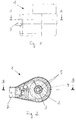
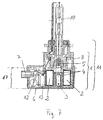
- FIGS. 1 to 3 provide different representations of a Embodiment of a high-voltage ignition module according to the invention 1.
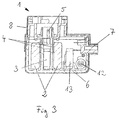
- Figs. 2 and 3 is the concentric arrangement a suppression choke 3 with respect to a toroidal transformer 2 clearly recognizable.
- the interference suppressor 3 is by means of a holding tube 4 fixed. On the holding tube 4 is a high-voltage side Connection contact 5 of the high-voltage ignition module 1 attached. This can e.g. as an outgoing conductor for one to the high-voltage ignition module 1 gas discharge lamp 10 to be connected (see FIG. 6 and 7) serve. He is in the present embodiment forked in two parts (see Fig. 2).
- the toroidal transformer 2, the interference suppression 3, a Ignition capacitor, a spark gap 12 and an ohmic resistor are arranged on a component carrier 6. It was the spatial division of the components on the component carrier 6 made so that in a first area of the component carrier 6 including high voltage components only of the toroidal transformer 2 and the suppression choke 3 and in one of the first area of the component carrier 6 spatially separate second area of the component carrier 6 only low voltage leading components, in the present embodiment So the ignition capacitor, the spark gap 12, the ohmic resistance and a low-voltage suppressor 13, are arranged.
- the component carrier 6 consists of an electrically insulating Plastic and is with a further housing part 8 of the High-voltage ignition module 1 lockable.
- the component carrier 6 with a collar space 7, which for receiving a Connection cable connector is used. In the locked state can the component carrier 6 a part of the outer contour of the high-voltage ignition module form.
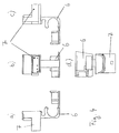
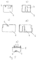
- FIG. 4 and 5 show a first and a second, respectively Embodiment of the component carrier 6 in different Views.
- the second embodiment shown in FIG. 5 of the component carrier 6 has a locking lug 9 which, like shown in Fig. 5e, in a recess of the further housing part 8 engages and causes the above-mentioned locking.
- the use of the High-voltage ignition module 1 according to the invention as an ignition module for a gas discharge lamp 10, e.g. for one in the field Xenon lamp commonly used in automotive lighting.
- 6 and 7 show a gas discharge lamp 10, the base 11 of which partly by an embodiment of the invention High voltage ignition module 1 is formed.
- the reference numbers of the individual components in FIGS. 6 and 7 correspond to the Reference numerals used in Fig. 3.
- High voltage ignition module 1 shown are all components up to the casting height marked with the reference number 17 embedded in an electrically insulating potting compound.
Abstract
Description
- Fig. 1
- eine Seitenansicht eines Ausführungsbeispiels eines erfindungsgemäßen Hochspannungszündmoduls,
- Fig. 2
- eine Schnittdarstellung entlang der Linie A-A von Fig. 1,
- Fig. 3
- eine Schnittdarstellung entlang der Linie B-B von Fig. 2,
- Fig. 4
- ein erstes Ausführungsbeispiel eines Bauteilträgers des erfindungsgemäßen Hochspannungszündmoduls in Vorderansicht (b), Draufsicht (d) und zwei Seitenansichten (a, c),
- Fig. 5
- ein zweites Ausführungsbeispiel eines Bauteilträgers und zugleich Gehäuseteils des erfindungsgemäßen Hochspannungszündmoduls in zwei Seitenansichten (a, c), zwei Querschnittsansichten (b, d) und in mit einem weiteren Gehäuseteil des erfindungsgemäßen Hochspannungszündmoduls verrasteter Stellung (e),
- Fig. 6
- eine Gasentladungslampe mit einem Ausführungsbeispiel des erfindungsgemäßen Hochspannungszündmoduls als Sockelteil und
- Fig. 7
- die Anordnung von Fig. 6 im Querschnitt.
Claims (11)
- Hochspannungszündmodul (1) mit einem als Ringkerntransformator (2) ausgebildeten Zündtransformator und einer Entstördrossel (3), dadurch gekennzeichnet, daß die Entstördrossel (3) innerhalb des Ringkerntransformators (2) angeordnet ist.
- Hochspannungszündmodul (1) nach Anspruch 1, dadurch gekennzeichnet, daß die Entstördrossel (3) konzentrisch zum Ringkerntransformator (2) angeordnet ist.
- Hochspannungszündmodul (1) nach einem der vorhergehenden Ansprüche, dadurch gekennzeichnet, daß die Entstördrossel (3) mittels eines Halterohres (4) fixiert und an dem Halterohr (4) ein hochspannungsseitiger Anschlußkontakt (5) des Hochspannungszündmoduls (1) angebracht ist.
- Hochspannungszündmodul (1) nach einem der vorhergehenden Ansprüche, dadurch gekennzeichnet, daß der Ringkerntransformator (2) und die Entstördrossel (3) gemeinsam auf einem Bauteilträger (6) angeordnet sind.
- Hochspannungszündmodul (1) nach Anspruch 4, dadurch gekennzeichnet, daß auf dem Bauteilträger (6)in einem ersten Bereich des Bauteilträgers (6) nur Hochspannung führende Bauelemente einschließlich des Ringkerntransformators (2) und der Entstördrossel (3) undin einem von dem ersten Bereich des Bauteilträgers (6) räumlich getrennten zweiten Bereich des Bauteilträgers (6) nur Niederspannung führende Bauelemente (12, 13) angeordnet sind.
- Hochspannungszündmodul (1) nach Anspruch 5, dadurch gekennzeichnet, daß zumindestens die Hochspannung führenden Bauelemente einschließlich des Ringkerntransformators (2) und der Entstördrossel (3) in einer elektrisch isolierenden Vergußmasse eingebettet sind.
- Hochspannungszündmodul (1) nach einem der Ansprüche 4 bis 6, dadurch gekennzeichnet, daß der Bauteilträger (6) aus einem elektrisch isolierenden Kunststoff besteht.
- Hochspannungszündmodul (1) nach einem der Ansprüche 4 bis 7, dadurch gekennzeichnet, daß der Bauteilträger (6) mit einem Kragenraum (7), der zur Aufnahme eines Anschlußkabelsteckers dient, versehen ist.
- Hochspannungszündmodul (1) nach einem der Ansprüche 4 bis 8, dadurch gekennzeichnet, daß der Bauteilträger (6) mit mindestens einem weiteren Gehäuseteil (8) des Hochspannungszündmoduls (1) verrastbar ist.
- Hochspannungszündmodul (1) nach Anspruch 9, dadurch gekennzeichnet, daß der Bauteilträger (6) im verrasteten Zustand einen Teil der Außenkontur des Hochspannungszündmoduls (1) bildet.
- Hochspannungszündmodul (1) nach einem der vorhergehenden Ansprüche, dadurch gekennzeichnet, daß es als Gasentladungslampensockel (11) oder als Teil eines Gasentladungslampensockels (11) ausgebildet ist.
Applications Claiming Priority (2)
| Application Number | Priority Date | Filing Date | Title |
|---|---|---|---|
| DE1999139310 DE19939310C2 (de) | 1999-08-19 | 1999-08-19 | Hochspannungszündmodul |
| DE19939310 | 1999-08-19 |
Publications (2)
| Publication Number | Publication Date |
|---|---|
| EP1077590A2 true EP1077590A2 (de) | 2001-02-21 |
| EP1077590A3 EP1077590A3 (de) | 2001-12-12 |
Family
ID=7918890
Family Applications (1)
| Application Number | Title | Priority Date | Filing Date |
|---|---|---|---|
| EP00117030A Withdrawn EP1077590A3 (de) | 1999-08-19 | 2000-08-08 | Hochspannungszündmodul |
Country Status (2)
| Country | Link |
|---|---|
| EP (1) | EP1077590A3 (de) |
| DE (1) | DE19939310C2 (de) |
Cited By (4)
| Publication number | Priority date | Publication date | Assignee | Title |
|---|---|---|---|---|
| WO2005045878A2 (en) | 2003-11-07 | 2005-05-19 | Philips Intellectual Property & Standards Gmbh | Starter housing for gas discharge lamp, and method of mounting same |
| WO2006027268A1 (de) * | 2004-09-09 | 2006-03-16 | Vogt Electronic Ag | Trägerbauteil, entstördrosselvorrichtung und verfahren zur herstellung |
| US7760061B2 (en) | 2006-08-31 | 2010-07-20 | General Electric Company | Lamp transformer |
| US7855625B2 (en) | 2006-08-31 | 2010-12-21 | General Electric Company | Lamp transformer |
Citations (5)
| Publication number | Priority date | Publication date | Assignee | Title |
|---|---|---|---|---|
| GB2276714A (en) * | 1993-03-30 | 1994-10-05 | Bosch Gmbh Robert | Headlight for vehicles |
| DE19624724A1 (de) * | 1995-06-29 | 1997-01-09 | Valeo Vision | Filtereinheit für einen Verbinder zu einer Entladungslampe, insbesondere in einem Kraftfahrzeugscheinwerfer, Baugruppe aus einem Verbinder und einer solchen Fitereinheit, und Scheinwerfer mit einer solchen Baugruppe |
| DE19645752A1 (de) * | 1995-11-06 | 1997-05-15 | Koito Mfg Co Ltd | Entladungslampenbeleuchtungsvorrichtung |
| EP0891123A1 (de) * | 1997-07-11 | 1999-01-13 | MAGNETI MARELLI S.p.A. | Vorrichtung zum Betrieb von Gasentladungslampen, insbesondere für Kraftfahrzeuge |
| DE19751548A1 (de) * | 1997-11-20 | 1999-06-02 | Vogt Electronic Ag | Zündtransformator für eine Entladungslampe |
Family Cites Families (3)
| Publication number | Priority date | Publication date | Assignee | Title |
|---|---|---|---|---|
| DE19610385A1 (de) * | 1996-03-16 | 1997-09-18 | Bosch Gmbh Robert | Gasentladungslampe, insbesondere für Kraftfahrzeug-Scheinwerfer |
| DE19610388A1 (de) * | 1996-03-16 | 1997-09-18 | Bosch Gmbh Robert | Zündeinrichtung für eine Entladungslampe |
| DE19803139A1 (de) * | 1998-01-28 | 1999-07-29 | Patent Treuhand Ges Fuer Elektrische Gluehlampen Mbh | Zündvorrichtung für eine Entladungslampe |
-
1999
- 1999-08-19 DE DE1999139310 patent/DE19939310C2/de not_active Expired - Fee Related
-
2000
- 2000-08-08 EP EP00117030A patent/EP1077590A3/de not_active Withdrawn
Patent Citations (5)
| Publication number | Priority date | Publication date | Assignee | Title |
|---|---|---|---|---|
| GB2276714A (en) * | 1993-03-30 | 1994-10-05 | Bosch Gmbh Robert | Headlight for vehicles |
| DE19624724A1 (de) * | 1995-06-29 | 1997-01-09 | Valeo Vision | Filtereinheit für einen Verbinder zu einer Entladungslampe, insbesondere in einem Kraftfahrzeugscheinwerfer, Baugruppe aus einem Verbinder und einer solchen Fitereinheit, und Scheinwerfer mit einer solchen Baugruppe |
| DE19645752A1 (de) * | 1995-11-06 | 1997-05-15 | Koito Mfg Co Ltd | Entladungslampenbeleuchtungsvorrichtung |
| EP0891123A1 (de) * | 1997-07-11 | 1999-01-13 | MAGNETI MARELLI S.p.A. | Vorrichtung zum Betrieb von Gasentladungslampen, insbesondere für Kraftfahrzeuge |
| DE19751548A1 (de) * | 1997-11-20 | 1999-06-02 | Vogt Electronic Ag | Zündtransformator für eine Entladungslampe |
Cited By (6)
| Publication number | Priority date | Publication date | Assignee | Title |
|---|---|---|---|---|
| WO2005045878A2 (en) | 2003-11-07 | 2005-05-19 | Philips Intellectual Property & Standards Gmbh | Starter housing for gas discharge lamp, and method of mounting same |
| EP1683182B1 (de) * | 2003-11-07 | 2015-04-08 | Philips Intellectual Property & Standards GmbH | Startergehäuse für eine gasentladungslampe und anbringverfahren dafür |
| WO2006027268A1 (de) * | 2004-09-09 | 2006-03-16 | Vogt Electronic Ag | Trägerbauteil, entstördrosselvorrichtung und verfahren zur herstellung |
| US8222987B2 (en) | 2004-09-09 | 2012-07-17 | Vogt Electronic Ag | Supporting component, interference suppression coil device and method for the manufacture thereof |
| US7760061B2 (en) | 2006-08-31 | 2010-07-20 | General Electric Company | Lamp transformer |
| US7855625B2 (en) | 2006-08-31 | 2010-12-21 | General Electric Company | Lamp transformer |
Also Published As
| Publication number | Publication date |
|---|---|
| DE19939310A1 (de) | 2001-03-08 |
| EP1077590A3 (de) | 2001-12-12 |
| DE19939310C2 (de) | 2001-06-13 |
Similar Documents
| Publication | Publication Date | Title |
|---|---|---|
| DE3109766C2 (de) | ||
| DE2810514A1 (de) | Steckverbinder mit stoerschutz | |
| EP0304038B2 (de) | Zündeinheit für Verbrennungsmotoren | |
| DE4206433A1 (de) | Kapazitives trennstueck | |
| DE19610388A1 (de) | Zündeinrichtung für eine Entladungslampe | |
| EP1352547B1 (de) | Gasentladungslampensockel mit zündeinrichtung | |
| EP0793243B1 (de) | Transformator | |
| DE19939310C2 (de) | Hochspannungszündmodul | |
| DE3203021A1 (de) | Steckverbinder mit entstoereinrichtung | |
| DE69831949T2 (de) | Dioden-split-hochspannungstransformator | |
| DE2741385A1 (de) | Magnetron-einrichtung | |
| DE3540547A1 (de) | Hochspannungsstromwandler und verfahren zur herstellung eines derartigen hochspannungsstromwandlers | |
| WO2004021567A1 (de) | Durchführungsbauelement, filterschaltung mit dem durchführungsbauelement und schirmwand für geschirmte räume | |
| DE4444554A1 (de) | Gekapselte elektrische Hochspannungsleitung | |
| DE2340773A1 (de) | Uebergabesteckverbindung | |
| DE4132813C1 (en) | Electrically powered fuel pump for motor vehicle - suppresses radio interference by having two radio interference by having two capacitors in series for projecting terminal pins | |
| DE2745061A1 (de) | Vorrichtung zur unterdrueckung von zuendstoerungen bei motorraedern | |
| EP0269074B1 (de) | Zeilentransformator | |
| DE3604730C2 (de) | ||
| DE19606184A1 (de) | Baugruppe | |
| DE3637350C2 (de) | ||
| DE4008424C2 (de) | ||
| EP0273993B1 (de) | Als Geräteanschluss- und Schaltklemme ausgebildete elektrische Klemmvorrichtung | |
| DE4238328A1 (de) | Kapazitives Trennstück | |
| DE2344085C3 (de) | Hochspannungsgleichrichteranordnung |
Legal Events
| Date | Code | Title | Description |
|---|---|---|---|
| PUAI | Public reference made under article 153(3) epc to a published international application that has entered the european phase |
Free format text: ORIGINAL CODE: 0009012 |
|
| AK | Designated contracting states |
Kind code of ref document: A2 Designated state(s): AT BE CH CY DE DK ES FI FR GB GR IE IT LI LU MC NL PT SE |
|
| AX | Request for extension of the european patent |
Free format text: AL;LT;LV;MK;RO;SI |
|
| PUAL | Search report despatched |
Free format text: ORIGINAL CODE: 0009013 |
|
| AK | Designated contracting states |
Kind code of ref document: A3 Designated state(s): AT BE CH CY DE DK ES FI FR GB GR IE IT LI LU MC NL PT SE |
|
| AX | Request for extension of the european patent |
Free format text: AL;LT;LV;MK;RO;SI |
|
| RIC1 | Information provided on ipc code assigned before grant |
Free format text: 7H 05B 41/04 A, 7H 05B 41/292 B |
|
| 17P | Request for examination filed |
Effective date: 20020527 |
|
| AKX | Designation fees paid |
Free format text: AT BE CH CY DE DK ES FI FR GB GR IE IT LI LU MC NL PT SE |
|
| 17Q | First examination report despatched |
Effective date: 20021212 |
|
| GRAH | Despatch of communication of intention to grant a patent |
Free format text: ORIGINAL CODE: EPIDOS IGRA |
|
| STAA | Information on the status of an ep patent application or granted ep patent |
Free format text: STATUS: THE APPLICATION HAS BEEN WITHDRAWN |
|
| 18W | Application withdrawn |
Effective date: 20030612 |