EP1077590A2 - High voltage starting module - Google Patents
High voltage starting module Download PDFInfo
- Publication number
- EP1077590A2 EP1077590A2 EP00117030A EP00117030A EP1077590A2 EP 1077590 A2 EP1077590 A2 EP 1077590A2 EP 00117030 A EP00117030 A EP 00117030A EP 00117030 A EP00117030 A EP 00117030A EP 1077590 A2 EP1077590 A2 EP 1077590A2
- Authority
- EP
- European Patent Office
- Prior art keywords
- ignition module
- voltage ignition
- voltage
- component carrier
- toroidal transformer
- Prior art date
- Legal status (The legal status is an assumption and is not a legal conclusion. Google has not performed a legal analysis and makes no representation as to the accuracy of the status listed.)
- Withdrawn
Links
Images

Classifications
-
- H—ELECTRICITY
- H05—ELECTRIC TECHNIQUES NOT OTHERWISE PROVIDED FOR
- H05B—ELECTRIC HEATING; ELECTRIC LIGHT SOURCES NOT OTHERWISE PROVIDED FOR; CIRCUIT ARRANGEMENTS FOR ELECTRIC LIGHT SOURCES, IN GENERAL
- H05B41/00—Circuit arrangements or apparatus for igniting or operating discharge lamps
- H05B41/02—Details
- H05B41/04—Starting switches
- H05B41/042—Starting switches using semiconductor devices
Definitions
- the invention relates to a high-voltage ignition module an ignition transformer designed as a toroidal transformer and a suppression choke.
- DE 196 10 385 A1 describes a high-voltage ignition module known with a toroidal transformer, in which a reduction the size is achieved in that part of the Lamp vessel arranged within the toroidal transformer is.
- the use of suppressor chokes is, however, in DE 196 10 385 A1 not disclosed.
- a generic high voltage ignition module according to the The preamble of claim 1 is customary in itself, from the Known from DE 198 03 139 A1 and thus prior art. From known high-voltage ignition modules with the prior art Toroidal transformer and suppressor choke, however, have one relatively large volume and poor assembly properties in terms of the individual components.
- the invention is therefore based on the object To provide high voltage ignition module, which is a more compact Design as the high-voltage ignition modules known from the prior art having.
- this object is achieved by a High-voltage ignition module according to claim 1.
- the arrangement of the Suppression choke within the toroidal transformer saves Space and in this way enables a reduction in the High-voltage ignition module construction volume. So far, suppression chokes have been used in high-voltage ignition modules due to certain EMC considerations always only "outside" the toroidal transformer, d. H. off-axis with respect to the toroidal transformer, been arranged, from which the relatively large volume of the known high-voltage ignition modules resulted.
- High voltage ignition module are the subject of Claims 2 to 11.
- the embodiment according to claim 3 enables the connection of the interference suppression choke tube to a high-voltage side Connection contact of the high-voltage ignition module in a particularly advantageous manner, a compact design.
- the existing component carrier according to claim 4 can during assembly of the high-voltage ignition module and thus enables a particularly simple assembly technology.
- the preferred embodiment according to claim 8 provided collar space for receiving a connection cable connector can be fitted externally during the assembly process and thus ensures a particularly simple assembly technology when assembling the high-voltage ignition module.
- this is High-voltage ignition module according to the invention as a gas discharge lamp base or as part of a gas discharge lamp base educated.
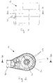
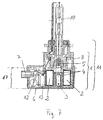
- FIGS. 1 to 3 provide different representations of a Embodiment of a high-voltage ignition module according to the invention 1.
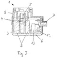
- Figs. 2 and 3 is the concentric arrangement a suppression choke 3 with respect to a toroidal transformer 2 clearly recognizable.
- the interference suppressor 3 is by means of a holding tube 4 fixed. On the holding tube 4 is a high-voltage side Connection contact 5 of the high-voltage ignition module 1 attached. This can e.g. as an outgoing conductor for one to the high-voltage ignition module 1 gas discharge lamp 10 to be connected (see FIG. 6 and 7) serve. He is in the present embodiment forked in two parts (see Fig. 2).
- the toroidal transformer 2, the interference suppression 3, a Ignition capacitor, a spark gap 12 and an ohmic resistor are arranged on a component carrier 6. It was the spatial division of the components on the component carrier 6 made so that in a first area of the component carrier 6 including high voltage components only of the toroidal transformer 2 and the suppression choke 3 and in one of the first area of the component carrier 6 spatially separate second area of the component carrier 6 only low voltage leading components, in the present embodiment So the ignition capacitor, the spark gap 12, the ohmic resistance and a low-voltage suppressor 13, are arranged.
- the component carrier 6 consists of an electrically insulating Plastic and is with a further housing part 8 of the High-voltage ignition module 1 lockable.
- the component carrier 6 with a collar space 7, which for receiving a Connection cable connector is used. In the locked state can the component carrier 6 a part of the outer contour of the high-voltage ignition module form.
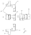
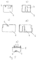
- FIG. 4 and 5 show a first and a second, respectively Embodiment of the component carrier 6 in different Views.
- the second embodiment shown in FIG. 5 of the component carrier 6 has a locking lug 9 which, like shown in Fig. 5e, in a recess of the further housing part 8 engages and causes the above-mentioned locking.
- the use of the High-voltage ignition module 1 according to the invention as an ignition module for a gas discharge lamp 10, e.g. for one in the field Xenon lamp commonly used in automotive lighting.
- 6 and 7 show a gas discharge lamp 10, the base 11 of which partly by an embodiment of the invention High voltage ignition module 1 is formed.
- the reference numbers of the individual components in FIGS. 6 and 7 correspond to the Reference numerals used in Fig. 3.
- High voltage ignition module 1 shown are all components up to the casting height marked with the reference number 17 embedded in an electrically insulating potting compound.
Landscapes
- Connector Housings Or Holding Contact Members (AREA)
- Feeding, Discharge, Calcimining, Fusing, And Gas-Generation Devices (AREA)
- Coils Or Transformers For Communication (AREA)
Abstract
Description
Die Erfindung betrifft ein Hochspannungszündmodul mit einem als Ringkerntransformator ausgebildeten Zündtransformator und einer Entstördrossel.The invention relates to a high-voltage ignition module an ignition transformer designed as a toroidal transformer and a suppression choke.
Aus der DE 196 10 385 A1 ist ein Hochspannungszündmodul mit einem Ringkerntransformator bekannt, bei dem eine Verringerung der Baugröße dadurch erreicht wird, daß ein Teil des Lampengefässes innerhalb des Ringkerntransformators angeordnet ist. Die Verwendung von Entstördrosseln ist jedoch in der DE 196 10 385 A1 nicht offenbart.DE 196 10 385 A1 describes a high-voltage ignition module known with a toroidal transformer, in which a reduction the size is achieved in that part of the Lamp vessel arranged within the toroidal transformer is. The use of suppressor chokes is, however, in DE 196 10 385 A1 not disclosed.
Aus der DE 196 10 388 A1 ist es bekannt, innerhalb eines Zündtransformators eines Hochspannungszündmoduls ein kapazitives Element anzuordnen, wodurch sich ein kompakter Aufbau ergibt. Jedoch sind auch in der DE 196 10 388 A1 keine Entstördrosseln offenbart.From DE 196 10 388 A1 it is known within a Ignition transformer of a high-voltage ignition module a capacitive Arrange element, resulting in a compact structure results. However, in DE 196 10 388 A1 there are also no interference suppression chokes disclosed.
Ein gattungsgemäßes Hochspannungszündmodul gemäß dem
Oberbegriff des Anspruchs 1 ist an sich handelsüblich, aus der
DE 198 03 139 A1 bekannt und somit Stand der Technik. Die aus
dem Stand der Technik bekannten Hochspannungszündmodule mit
Ringkerntransformator und Entstördrossel haben jedoch ein
relativ großes Bauvolumen und schlechte Montageeigenschaften
in Bezug auf die Einzelkomponenten.A generic high voltage ignition module according to the
The preamble of
Der Erfindung liegt daher die Aufgabe zugrunde, ein Hochspannungszündmodul bereitzustellen, das eine kompaktere Bauform als die aus dem Stand der Technik bekannten Hochspannungszündmodule aufweist.The invention is therefore based on the object To provide high voltage ignition module, which is a more compact Design as the high-voltage ignition modules known from the prior art having.
Erfindungsgemäß wird diese Aufgabe gelöst durch ein
Hochspannungszündmodul gemäß Anspruch 1. Die Anordnung der
Entstördrossel innerhalb des Ringkerntransformators spart
Platz und ermöglicht auf diese Weise eine Verringerung des
Hochspannungszündmodulbauvolumens. Bisher waren Entstördrosseln
in Hochspannungszündmodulen aufgrund bestimmter EMV-Überlegungen
stets nur "außerhalb" des Ringkerntransformators,
d. h. bezüglich des Ringkerntransformators achsenversetzt,
angeordnet worden, woraus das relativ große Bauvolumen der aus
dem Stand der Technik bekannten Hochspannungszündmodule resultierte.According to the invention, this object is achieved by a
High-voltage ignition module according to
Vorteilhafte und bevorzugte Ausführungsformen des erfindungsgemäßen
Hochspannungszündmoduls sind Gegenstand der
Patentansprüche 2 bis 11.Advantageous and preferred embodiments of the invention
High voltage ignition module are the subject of
Die Ausführungsform nach Anspruch 3 ermöglicht aufgrund
der Verbindung des Entstördrosselhalterohres mit einem hochspannungsseitigen
Anschlußkontakt des Hochspannungszündmoduls
in besonders vorteilhafter Weise eine kompakte Bauart.The embodiment according to
Der gemäß Anspruch 4 vorhandene Bauteilträger kann während
der Montage des Hochspannungszündmoduls extern bestückt
werden und ermöglicht so eine besonders einfache Montagetechnologie.The existing component carrier according to
Die konsequente räumliche Trennung der Hochspannung
führenden Bauelemente von den Niederspannung führenden Bauelementen
in der besonders bevorzugten Ausführungsform nach
Anspruch 5 gewährleistet eine hohe Betriebssicherheit des
erfindungsgemäßen Hochspannungszündmoduls. Zur Begriffsdefinition
sei angemerkt, daß unter "Niederspannung" hier Spannungen
bis zu einigen kV verstanden werden sollen. Im Gegensatz dazu
bezeichnet der Begriff "Hochspannung" hier Spannungen ab etwa
10 kV, insbesondere Spannungen von einigen 10 kV.The consequent spatial separation of the high voltage
leading components from the low voltage leading components
in the particularly
Die Ausführungsformen nach den Ansprüchen 6 und 7 gewährleisten
eine besonders gute Hochspannungsisolation und damit
eine besonders gute Betriebssicherheit.Ensure the embodiments according to
Der in der bevorzugten Ausführungsform nach Anspruch 8
vorgesehene Kragenraum zur Aufnahme eines Anschlußkabelsteckers
ist während des Montagevorgangs extern bestückbar und
gewährleistet so eine besonders einfache Montagetechnologie
beim Zusammenbau des Hochspannungszündmoduls.The preferred embodiment according to
Ebenfalls im Sinne der Gewährleistung einer besonders
einfachen Montagetechnologie ist die gemäß den besonders
bevorzugten Ausführungsformen nach den Ansprüchen 9 und 10
vorgesehene Verrastbarkeit des Bauteilträgers mit mindestens
einem weiteren Gehäuseteil des Hochspannungszündmoduls.Also in the sense of guaranteeing a special
simple assembly technology is according to the special
preferred embodiments according to
In einem besonders bevorzugten Anwendungsfall ist das erfindungsgemäße Hochspannungszündmodul als Gasentladungslampensockel oder als Teil eines Gasentladungslampensockels ausgebildet.In a particularly preferred application, this is High-voltage ignition module according to the invention as a gas discharge lamp base or as part of a gas discharge lamp base educated.
Ausführungsbeispiele des erfindungsgemäßen Hochspannungszündmoduls werden nachfolgend anhand von Figuren beschrieben. Es zeigt:
- Fig. 1
- eine Seitenansicht eines Ausführungsbeispiels eines erfindungsgemäßen Hochspannungszündmoduls,
- Fig. 2
- eine Schnittdarstellung entlang der Linie A-A von Fig. 1,
- Fig. 3
- eine Schnittdarstellung entlang der Linie B-B von Fig. 2,
- Fig. 4
- ein erstes Ausführungsbeispiel eines Bauteilträgers des erfindungsgemäßen Hochspannungszündmoduls in Vorderansicht (b), Draufsicht (d) und zwei Seitenansichten (a, c),
- Fig. 5
- ein zweites Ausführungsbeispiel eines Bauteilträgers und zugleich Gehäuseteils des erfindungsgemäßen Hochspannungszündmoduls in zwei Seitenansichten (a, c), zwei Querschnittsansichten (b, d) und in mit einem weiteren Gehäuseteil des erfindungsgemäßen Hochspannungszündmoduls verrasteter Stellung (e),
- Fig. 6
- eine Gasentladungslampe mit einem Ausführungsbeispiel des erfindungsgemäßen Hochspannungszündmoduls als Sockelteil und
- Fig. 7
- die Anordnung von Fig. 6 im Querschnitt.
- Fig. 1
- 2 shows a side view of an exemplary embodiment of a high-voltage ignition module according to the invention,
- Fig. 2
- 2 shows a sectional illustration along the line AA from FIG. 1,
- Fig. 3
- 3 shows a sectional illustration along the line BB from FIG. 2,
- Fig. 4
- a first embodiment of a component carrier of the high-voltage ignition module according to the invention in front view (b), top view (d) and two side views (a, c),
- Fig. 5
- a second embodiment of a component carrier and at the same time housing part of the high-voltage ignition module according to the invention in two side views (a, c), two cross-sectional views (b, d) and in position (e) locked with a further housing part of the high-voltage ignition module according to the invention,
- Fig. 6
- a gas discharge lamp with an embodiment of the high-voltage ignition module according to the invention as a base part and
- Fig. 7
- the arrangement of Fig. 6 in cross section.
Die Fig. 1 bis 3 liefern verschiedene Darstellungen eines
Ausführungsbeispiels eines erfindungsgemäßen Hochspannungszündmoduls
1. In den Fig. 2 und 3 ist die konzentrische Anordnung
einer Entstördrossel 3 in Bezug auf einen Ringkerntransformator
2 deutlich erkennbar.1 to 3 provide different representations of a
Embodiment of a high-voltage ignition module according to the
Die Entstördrossel 3 wird mittels eines Halterohres 4
fixiert. An dem Halterohr 4 ist ein hochspannungsseitiger
Anschlußkontakt 5 des Hochspannungszündmoduls 1 angebracht.
Dieser kann z.B. als Hinleiter für eine an das Hochspannungszündmodul
1 anzuschließende Gasentladungslampe 10 (sh. Fig. 6
und 7) dienen. Er ist im vorliegenden Ausführungsbeispiel
zweiteilig gegabelt (sh. Fig. 2).The
Der Ringkerntransformator 2, die Entstördrossel 3, ein
Zündkondensator, eine Funkenstrecke 12 und ein ohmscher Widerstand
sind auf einem Bauteilträger 6 angeordnet. Dabei wurde
die räumliche Aufteilung der Bauelemente auf dem Bauteilträger
6 so vorgenommen, daß in einem ersten Bereich des Bauteilträgers
6 nur Hochspannung führende Bauelemente einschließlich
des Ringkerntransformators 2 und der Entstördrossel 3 und in
einem von dem ersten Bereich des Bauteilträgers 6 räumlich
getrennten zweiten Bereich des Bauteilträgers 6 nur Niederspannung
führende Bauelemente, im vorliegenden Ausführungsbeispiel
also der Zündkondensator, die Funkenstrecke 12, der
ohmsche Widerstand sowie eine Niederspannungs-Entstördrossel
13, angeordnet sind.The
Der Bauteilträger 6 besteht aus einem elektrisch isolierenden
Kunststoff und ist mit einem weiteren Gehäuseteil 8 des
Hochspannungszündmoduls 1 verrastbar. Außerdem ist der Bauteilträger
6 mit einem Kragenraum 7, der zur Aufnahme eines
Anschlußkabelsteckers dient, versehen. Im verrasteten Zustand
kann der Bauteilträger 6 einen Teil der Außenkontur des Hochspannungszündmoduls
bilden.The
Die Fig. 4 und 5 zeigen ein erstes bzw. ein zweites
Ausführungsbeispiel des Bauteilträgers 6 in verschiedenen
Ansichten. Das in Fig. 5 dargestellte zweite Ausführungsbeispiel
des Bauteilträgers 6 weist eine Rastnase 9 auf, die, wie
in Fig. 5e dargestellt, in eine Ausnehmung des weiteren Gehäuseteils
8 eingreift und so die obengenannte Verrastung bewirkt.4 and 5 show a first and a second, respectively
Embodiment of the
In der Praxis besonders bedeutsam ist die Verwendung des
erfindungsgemäßen Hochspannungszündmoduls 1 als Zündmodul für
eine Gasentladungslampe 10, wie z.B. für eine auf dem Gebiet
der Automobilbeleuchtung gebräuchliche Xenonlampe. Die Fig. 6
und 7 zeigen eine Gasentladungslampe 10, deren Sockel 11
teilweise durch ein Ausführungsbeispiel des erfindungsgemäßen
Hochspannungszündmoduls 1 gebildet wird. Die Bezugszeichen der
einzelnen Bauteile in den Fig. 6 und 7 entsprechen dabei den
in Fig. 3 verwendeten Bezugszeichen. Innerhalb des in Fig. 7
dargestellten Hochspannungszündmoduls 1 sind alle Bauelemente
bis zur mit dem Bezugszeichen 17 gekennzeichneten Vergußhöhe
in einer elektrisch isolierenden Vergußmasse eingebettet.In practice, the use of the
High-
Claims (11)
Applications Claiming Priority (2)
| Application Number | Priority Date | Filing Date | Title |
|---|---|---|---|
| DE1999139310 DE19939310C2 (en) | 1999-08-19 | 1999-08-19 | High voltage ignition module |
| DE19939310 | 1999-08-19 |
Publications (2)
| Publication Number | Publication Date |
|---|---|
| EP1077590A2 true EP1077590A2 (en) | 2001-02-21 |
| EP1077590A3 EP1077590A3 (en) | 2001-12-12 |
Family
ID=7918890
Family Applications (1)
| Application Number | Title | Priority Date | Filing Date |
|---|---|---|---|
| EP00117030A Withdrawn EP1077590A3 (en) | 1999-08-19 | 2000-08-08 | High voltage starting module |
Country Status (2)
| Country | Link |
|---|---|
| EP (1) | EP1077590A3 (en) |
| DE (1) | DE19939310C2 (en) |
Cited By (4)
| Publication number | Priority date | Publication date | Assignee | Title |
|---|---|---|---|---|
| WO2005045878A2 (en) | 2003-11-07 | 2005-05-19 | Philips Intellectual Property & Standards Gmbh | Starter housing for gas discharge lamp, and method of mounting same |
| WO2006027268A1 (en) * | 2004-09-09 | 2006-03-16 | Vogt Electronic Ag | Supporting component, interference suppression coil device, and production method |
| US7760061B2 (en) | 2006-08-31 | 2010-07-20 | General Electric Company | Lamp transformer |
| US7855625B2 (en) | 2006-08-31 | 2010-12-21 | General Electric Company | Lamp transformer |
Citations (5)
| Publication number | Priority date | Publication date | Assignee | Title |
|---|---|---|---|---|
| GB2276714A (en) * | 1993-03-30 | 1994-10-05 | Bosch Gmbh Robert | Headlight for vehicles |
| DE19624724A1 (en) * | 1995-06-29 | 1997-01-09 | Valeo Vision | EMC filter unit e.g. for motor vehicle discharge-type headlamp connector |
| DE19645752A1 (en) * | 1995-11-06 | 1997-05-15 | Koito Mfg Co Ltd | Discharge lamp e.g. headlamp for motor vehicle |
| EP0891123A1 (en) * | 1997-07-11 | 1999-01-13 | MAGNETI MARELLI S.p.A. | A device for operating a gas-discharge lamp, particularly for motor vehicles |
| DE19751548A1 (en) * | 1997-11-20 | 1999-06-02 | Vogt Electronic Ag | Discharge lamp starter transformer has a closed or gap core of electrically non-conductive material |
Family Cites Families (3)
| Publication number | Priority date | Publication date | Assignee | Title |
|---|---|---|---|---|
| DE19610388A1 (en) * | 1996-03-16 | 1997-09-18 | Bosch Gmbh Robert | Ignition device e.g. for discharge lamp of motor vehicle |
| DE19610385A1 (en) * | 1996-03-16 | 1997-09-18 | Bosch Gmbh Robert | Gas discharge lamp, in particular for motor vehicle headlights |
| DE19803139A1 (en) * | 1998-01-28 | 1999-07-29 | Patent Treuhand Ges Fuer Elektrische Gluehlampen Mbh | Ignition device for a discharge lamp |
-
1999
- 1999-08-19 DE DE1999139310 patent/DE19939310C2/en not_active Expired - Fee Related
-
2000
- 2000-08-08 EP EP00117030A patent/EP1077590A3/en not_active Withdrawn
Patent Citations (5)
| Publication number | Priority date | Publication date | Assignee | Title |
|---|---|---|---|---|
| GB2276714A (en) * | 1993-03-30 | 1994-10-05 | Bosch Gmbh Robert | Headlight for vehicles |
| DE19624724A1 (en) * | 1995-06-29 | 1997-01-09 | Valeo Vision | EMC filter unit e.g. for motor vehicle discharge-type headlamp connector |
| DE19645752A1 (en) * | 1995-11-06 | 1997-05-15 | Koito Mfg Co Ltd | Discharge lamp e.g. headlamp for motor vehicle |
| EP0891123A1 (en) * | 1997-07-11 | 1999-01-13 | MAGNETI MARELLI S.p.A. | A device for operating a gas-discharge lamp, particularly for motor vehicles |
| DE19751548A1 (en) * | 1997-11-20 | 1999-06-02 | Vogt Electronic Ag | Discharge lamp starter transformer has a closed or gap core of electrically non-conductive material |
Cited By (6)
| Publication number | Priority date | Publication date | Assignee | Title |
|---|---|---|---|---|
| WO2005045878A2 (en) | 2003-11-07 | 2005-05-19 | Philips Intellectual Property & Standards Gmbh | Starter housing for gas discharge lamp, and method of mounting same |
| EP1683182B1 (en) * | 2003-11-07 | 2015-04-08 | Philips Intellectual Property & Standards GmbH | Starter housing for gas discharge lamp, and method of mounting same |
| WO2006027268A1 (en) * | 2004-09-09 | 2006-03-16 | Vogt Electronic Ag | Supporting component, interference suppression coil device, and production method |
| US8222987B2 (en) | 2004-09-09 | 2012-07-17 | Vogt Electronic Ag | Supporting component, interference suppression coil device and method for the manufacture thereof |
| US7760061B2 (en) | 2006-08-31 | 2010-07-20 | General Electric Company | Lamp transformer |
| US7855625B2 (en) | 2006-08-31 | 2010-12-21 | General Electric Company | Lamp transformer |
Also Published As
| Publication number | Publication date |
|---|---|
| DE19939310A1 (en) | 2001-03-08 |
| EP1077590A3 (en) | 2001-12-12 |
| DE19939310C2 (en) | 2001-06-13 |
Similar Documents
| Publication | Publication Date | Title |
|---|---|---|
| DE3851478T2 (en) | Transformer. | |
| DE3109766C2 (en) | ||
| DE2810514A1 (en) | CONNECTOR WITH IMPACT PROTECTION | |
| EP0304038B2 (en) | Ignition unit for combustion engines | |
| DE4206433A1 (en) | Capacity separator for inner and outer leads of HF coaxial cable to be coupled together - has electrically conductive casing in two coaxial parts, each coupled to outer conductor and leaving meandering air gap in-between | |
| DE19610388A1 (en) | Ignition device e.g. for discharge lamp of motor vehicle | |
| DE69712859T2 (en) | Control device for vehicle lighting | |
| EP0793243A1 (en) | Transformer | |
| DE19939310C2 (en) | High voltage ignition module | |
| DE3203021A1 (en) | CONNECTOR WITH INTERFERENCE DEVICE | |
| DE69831949T2 (en) | DIODES-SPLIT HIGH VOLTAGE TRANSFORMER | |
| DE2741385A1 (en) | MAGNETRON DEVICE | |
| EP0123872A1 (en) | Zener diode barrier | |
| DE102019213722A1 (en) | INDUCTIVE COMPONENT | |
| DE3540547A1 (en) | High-voltage current transformer and a method for producing such a high-voltage current transformer | |
| DE29508111U1 (en) | Power contacting for a converter device | |
| WO2004021567A1 (en) | Feedthrough component, filter circuit provided with the feedthrough component, and shielding wall for shielded spaces | |
| DE2340773A1 (en) | Transfer plug connector for wiring system with spring strip - has terminal pins protruding above wiring plane for connection to respective cct. boards | |
| DE4444554A1 (en) | Encapsulated electrical high-voltage line | |
| DE19606184A1 (en) | Gas- and moisture-proof circuit module for screening wiring contact points in electrical apparatus | |
| DE4132813C1 (en) | Electrically powered fuel pump for motor vehicle - suppresses radio interference by having two radio interference by having two capacitors in series for projecting terminal pins | |
| DE2745061A1 (en) | DEVICE FOR THE SUPPRESSION OF IGNITION FAILURES IN MOTORCYCLES | |
| EP0269074B1 (en) | Line transformer | |
| DE3604730C2 (en) | ||
| DE4008424C2 (en) |
Legal Events
| Date | Code | Title | Description |
|---|---|---|---|
| PUAI | Public reference made under article 153(3) epc to a published international application that has entered the european phase |
Free format text: ORIGINAL CODE: 0009012 |
|
| AK | Designated contracting states |
Kind code of ref document: A2 Designated state(s): AT BE CH CY DE DK ES FI FR GB GR IE IT LI LU MC NL PT SE |
|
| AX | Request for extension of the european patent |
Free format text: AL;LT;LV;MK;RO;SI |
|
| PUAL | Search report despatched |
Free format text: ORIGINAL CODE: 0009013 |
|
| AK | Designated contracting states |
Kind code of ref document: A3 Designated state(s): AT BE CH CY DE DK ES FI FR GB GR IE IT LI LU MC NL PT SE |
|
| AX | Request for extension of the european patent |
Free format text: AL;LT;LV;MK;RO;SI |
|
| RIC1 | Information provided on ipc code assigned before grant |
Free format text: 7H 05B 41/04 A, 7H 05B 41/292 B |
|
| 17P | Request for examination filed |
Effective date: 20020527 |
|
| AKX | Designation fees paid |
Free format text: AT BE CH CY DE DK ES FI FR GB GR IE IT LI LU MC NL PT SE |
|
| 17Q | First examination report despatched |
Effective date: 20021212 |
|
| GRAH | Despatch of communication of intention to grant a patent |
Free format text: ORIGINAL CODE: EPIDOS IGRA |
|
| STAA | Information on the status of an ep patent application or granted ep patent |
Free format text: STATUS: THE APPLICATION HAS BEEN WITHDRAWN |
|
| 18W | Application withdrawn |
Effective date: 20030612 |