EP0123872A1 - Zener diode barrier - Google Patents
Zener diode barrier Download PDFInfo
- Publication number
- EP0123872A1 EP0123872A1 EP84103101A EP84103101A EP0123872A1 EP 0123872 A1 EP0123872 A1 EP 0123872A1 EP 84103101 A EP84103101 A EP 84103101A EP 84103101 A EP84103101 A EP 84103101A EP 0123872 A1 EP0123872 A1 EP 0123872A1
- Authority
- EP
- European Patent Office
- Prior art keywords
- zener barrier
- housing
- zener
- housing part
- barrier according
- Prior art date
- Legal status (The legal status is an assumption and is not a legal conclusion. Google has not performed a legal analysis and makes no representation as to the accuracy of the status listed.)
- Granted
Links
Images

Classifications
-
- H—ELECTRICITY
- H05—ELECTRIC TECHNIQUES NOT OTHERWISE PROVIDED FOR
- H05K—PRINTED CIRCUITS; CASINGS OR CONSTRUCTIONAL DETAILS OF ELECTRIC APPARATUS; MANUFACTURE OF ASSEMBLAGES OF ELECTRICAL COMPONENTS
- H05K5/00—Casings, cabinets or drawers for electric apparatus
- H05K5/0021—Side-by-side or stacked arrangements
-
- H—ELECTRICITY
- H05—ELECTRIC TECHNIQUES NOT OTHERWISE PROVIDED FOR
- H05K—PRINTED CIRCUITS; CASINGS OR CONSTRUCTIONAL DETAILS OF ELECTRIC APPARATUS; MANUFACTURE OF ASSEMBLAGES OF ELECTRICAL COMPONENTS
- H05K7/00—Constructional details common to different types of electric apparatus
- H05K7/14—Mounting supporting structure in casing or on frame or rack
- H05K7/1417—Mounting supporting structure in casing or on frame or rack having securing means for mounting boards, plates or wiring boards
Definitions
- the invention relates to an intrinsically safe Zener barrier according to the preamble of claim 1.
- Zener barriers which are used in potentially explosive areas, separate a non-intrinsically safe circuit from an intrinsically safe circuit.
- a Zener barrier of the type mentioned has become known from DE-OS 30 37 783.
- the housing which receives the circuit arrangement of the Zener barrier, consists of two housing parts, a cup-shaped housing upper part and a housing lower part which closes the housing upper part, both housing parts being connected to one another in that the interior of the housing is poured out with casting resin.
- the lower housing part receives a threaded bushing, and with the help of the threaded bushing, a potential equalization rail can be screwed against the outer surface of the lower housing part.
- a mounting foot is attached to the housing, which allows the Zener barrier to be snapped onto a C profile rail.
- Zener barrier is very compact, it should be noted that it consists of a total of three parts, the upper housing part, the lower housing part and the mounting foot. An additional component must also be provided for fastening and holding the equipotential bonding rail, namely the threaded bushing and the screw interacting with it.
- the object of the invention is to provide a Zener barrier of the type mentioned, which requires as few parts as possible and which can be snapped on not only on a C-profile mounting rail, but also on a top-hat mounting rail.
- the advantage of the invention is essentially that only a total of two parts are required, namely the one, shell-shaped housing part, and the lid, which is fastened to the housing part by means of a snap connection and casting resin with which the housing is poured out.
- no separate mounting foot is required, which must be provided to hold the Zener barrier; rather, the individual resilient projections are formed directly on the housing part and there on a narrow side surface, the design of the projections making it possible to snap onto a C-profile mounting rail or onto a top-hat mounting rail.
- a further embodiment of the invention consists in that a recess is provided on the side surface of the housing part, which is recessed relative to the side surface, that test connecting pins protrude outward through the recess, and that the recess after bending the test pins into a position running parallel to the recess is poured out with resin.
- the circuit arrangement While in the Zener diode according to DE-OS 30 37 783 the circuit arrangement must be checked before the potting, which entails the problem that even changes and damage to the Zener barrier can be caused by the potting process, the circuit arrangement can be implemented in the embodiment according to the invention first cast and after casting, that is to say in the finally finished state. This is due to the fact that the test pins protrude from a specially designed section of the housing and that after the test only the test pins need to be cast in.
- the cover is simply attached by snapping the cover onto the open side of the molded housing part; characterized in that according to the invention bow-shaped projections are arranged, which penetrate into the casting resin when the cover is placed on the side face and are thus surrounded by it and are held in a positive and non-positive manner after the casting resin has hardened, the fastening of the cover is on Housing part particularly simple.
- a further embodiment of the invention can be found in the characterizing features of claims 5 and 6 to take. Due to the particularly advantageous design of the projections, there is the possibility that the housing can be locked on a C-profile mounting rail or on a top-hat mounting rail. Additional spring elements or any additional mounting foot that has to be attached to the housing is not required in the embodiment according to the invention.
- a further embodiment of the invention can be such that the bottom part of the housing part and the cover cover the clamps and take them between them.
- the terminal receiving space, in which the terminals are arranged, is thereby formed by the extension or extensions of the base part and the cover and a boundary wall to the space to be poured out.
- the individual terminals are sufficiently separated from one another in accordance with the VDE regulations, so that in any case the permissible minimum air and creepage distances are observed.
- Another advantage of the invention is as follows: In DE-OS 30 37 783, the equipotential bonding bar is struck against the lower housing part from below. In the embodiment according to the invention there is a groove in one of the side walls of the housing part, namely in one of the boundary walls between the terminal receiving space and the space to be poured, into which potential equalization rails can be inserted. The equipotential bonding rail is then held by the casting resin and the attached cover. An additional screw connection for holding the equipotential bonding bar is not required. Further advantageous refinements and improvements of the invention can be found in the further subclaims. Based on the drawing, in which an embodiment of the invention is shown, the invention as well as further advantageous refinements and improvements and further advantages are to be explained and described in more detail.
- the zener barrier according to the invention which is designated overall by reference number 10, has a shell-shaped housing part 11 and a cover 12.
- the shell-shaped housing part 11 is rectangular in plan and is of narrow construction, the housing part 11 being open on one side, as can be seen in FIG. 5, and closed on this side by means of the cover 12.
- the housing part 11 receives a circuit board 13 which carries the individual circuit elements of the circuit arrangement for the intrinsically safe Zener barrier. Of these components, only a fuse 14 can be seen in the drawing in FIG. 5.
- the housing base has a bath-shaped indent 15, which has two spaced-apart openings 16 and 17, through which pins 18 and 19 attached to the circuit board 13 reach after inserting the circuit board 13, to the extent that they cover the outer side surface 20 of the housing part 11 tower above.
- These pins 18 and 19 are test pins with which the electrical test of the circuit arrangement can take place.
- the Zener barrier has a total of four terminals 23, 25, 26 and 27, the connecting lugs 28, 29 and 30 connected to the circuit board via the U-bracket 21 similar U-bracket 31 (only the U-bracket 31 of the terminal 25 can be seen) are.
- the connecting lugs 22, 28, 29 and 30 have passages, of which only the passage 32 of the terminal lug 28 is designated, which have an internal thread through which the clamping screws 23, 25, 26 and 27 can be screwed to the terminal lugs.
- each terminal receiving space is delimited by a boundary wall 37 and 28, which at the same time forms the separating or sealing wall for the casting resin 39 with which the housing is poured out.
- partition walls 40 and 41 connect to this boundary wall, which surround the clamping screws and thus each form a receiving space 42 and 43 for the clamping screws 23 and 25 with the boundary walls 37 and 38, that the angle of the longitudinal axis L of each clamping screw is pointed with respect to the longer narrow side edge, which is denoted by alpha, so that the four clamping screws 23 to 27 can be actuated from above, that is to say seen from the direction of arrow 0.
- the partitions serve to make the creepage distances, which are shown in dotted lines in FIG. 1 and designated by the reference number 44, sufficiently large.
- Equalization rail 46 inserted, which continues inwards into a U-shaped bracket 47 corresponding to the U-shaped bracket 31, the equipotential bonding rail being connected to the U-shaped bracket 47 with the circuit board or with the electrical components of the circuit arrangement of the circuit board 13 .
- a clamping screw 48 is attached to the outer end of the equipotential bonding bar 46.
- a total of four projections 49, 50, 51 and 52 are formed on the outer surface of the bottom wall 45.
- the projection 49 also called the first formation 49, has an inward-facing nose 53, which corresponds to an inward-facing nose 54 pointing toward the nose 53.
- the fourth formation 50 has a first support plane 55 which is in the immediate vicinity of the nose 53, and in the same way the third formation 51 has a support surface 56 which is in the region of the nose 54. It can be seen that the two lugs 53 and 54 together with the bearing surfaces 55 and 56 serve to hold the free leg ends of a top-hat rail 57.
- the nose 54 is formed in that a region 58, which extends perpendicular to the bottom wall 45, is adjoined by a V-shaped region 59, the tip of which forms the nose 54 and the open side of which points in a direction that runs parallel to the bottom wall.
- a groove 60 is formed on the third projection 51 and cooperates with the open V-side of the second formation 52 for receiving the leg ends of a C-shaped rail.
- the fourth formation 50 has, in addition to the bearing surface 55, a further bearing surface 62 against which one leg of the mounting rail 61 comes to rest.
- the first and third form 49 and 51 are relatively rigid, whereas the second form 52 is resilient, so that the Zener barrier or the housing can be snapped onto the two mounting rails.
- the lid 12 has a plurality of projections 63, 64, 65, 66 and 67; with the projections 64 to 67, the cover can be snapped onto the housing part 11; the two projections 63, of which only the projection on the right in FIG. 1 can be seen, are bow-shaped and penetrate into the interior of the casting resin 39, so that the casting resin completely surrounds the projections and thereby holds the cover in a form-fitting manner.
- an opening 72 is provided on the end wall 71 opposite the bottom surface or the bottom wall 45, to which a guide ring 73 connects or is surrounded by the opening 72, which guide ring 73 rests on an adjustable switching element 74.
- the guide ring 73 serves to seal that part of the adjustable switching element which has to be actuated from the outside after assembly of the Zener barrier so that the adjusting device remains accessible from the outside.
- FIG. 6 now show different interconnections of the potential rail of several Zener barriers.
- a top-hat mounting rail 80 which corresponds to the top-hat mounting rail 57 of FIG. 1, three Zener barriers 81, 82 and 83 snapped next to one another can be seen.
- the connecting terminals 84 to 86 are coupled by means of a busbar 87, at one end of which a connecting terminal 88 is molded or attached for a connecting conductor 89.
- connection terminals 84 to 86 are connected to one another by means of U-shaped conductor connection pieces 90 and 91, whereas in the embodiment of FIG. 8, connection conductors 92 to 94 are connected to the individual connection terminals 84 to 86, which are connected to one another using a verb connecting terminal 95 are connected. A further connecting or grounding conductor can then be connected to this connecting terminal 95.
Abstract
Die Erfindung bezieht sich auf eine eigensichere Zenerbarriere. Eine derartige Zenerbarriere (10) besitzt ein Gehäuse zur Aufnahme der auf einer Platine (13) aufgebrachten Schaltungsanordnung, an dem Mittel zum Aufschnappen der Zenerbarriere (10) auf eine Norm-Profiltragschiene (57, 61) angebracht sind. Ferner besitzt eine derartige Zenerbarriere Anschlußklemmen (23, 25, 26, 27) sowie eine Potentialausgleichsschiene (46). Zur Vereinfachung der Herstellung der Zenerbarriere (10) und insbesondere zur Verringerung der Einzelteile besitzt das Gehäuse ein schalenförmig ausgebildetes, nach einer Breitseite hin offenes Gehäuseteil (11) und einen mit dem Gehäuse mittels Verrastungsmittel (64, 65, 66 und 67) verrastenden Deckel, der nach Ausgießen des Gehäuses mit Gießharz (39) über am Deckel angeformte Bügel (63) formschlüssig verbunden ist. An einer der Schmalseiten, der Bodenseite, sind mehrere Ausformungen (49, 50, 51 und 52) angeformt, die so aufeinander abgestimmt sind, daß die Zenerbarriere wahlweise auf eine Hut-Profiltragschiene (57) oder eine C-Profiltragschiene (61) aufgeschnappt werden kann. Die Ausgestaltung der Zenerbarriere ist so, daß die Schaltungsanordnung im Inneren des Gehäuses nach dem Ausgießen geprüft werden kann.The invention relates to an intrinsically safe Zener barrier. Such a Zener barrier (10) has a housing for receiving the circuit arrangement applied to a circuit board (13), on which means for snapping the Zener barrier (10) onto a standard profile mounting rail (57, 61) are attached. Such a Zener barrier also has connecting terminals (23, 25, 26, 27) and a potential equalization rail (46). To simplify the manufacture of the zener barrier (10) and in particular to reduce the number of individual parts, the housing has a shell-shaped housing part (11) which is open on a broad side and a cover which latches with the housing by means of latching means (64, 65, 66 and 67), which, after the housing has been poured out, is connected in a form-fitting manner with casting resin (39) via brackets (63) formed on the cover. On one of the narrow sides, the bottom side, several formations (49, 50, 51 and 52) are formed, which are coordinated so that the Zener barrier can be snapped onto a top-hat rail (57) or a C-rail (61) can. The design of the Zener barrier is such that the circuit arrangement inside the housing can be checked after pouring.
Description
Die Erfindung betrifft eine eigensichere Zenerbarriere nach dem Oberbegriff des Anspruches 1.The invention relates to an intrinsically safe Zener barrier according to the preamble of
Derartige Zenerbarrieren, die in explosionsgefährdeten Bereichen eingesetzt werden, trennen ein nicht eigensicheren Stromkreis von einem eigensicheren Stromkreis.Such Zener barriers, which are used in potentially explosive areas, separate a non-intrinsically safe circuit from an intrinsically safe circuit.
Eine Zenerbarriere der eingangs genannten Art ist aus der DE-OS 30 37 783 bekanntgeworden. Das Gehäuse, das die Schaltungsanordnung der Zenerbarriere aufnimmt, besteht aus zwei Gehäuseteilen, einem becherförmigen Gehäuseoberteil und einem das Gehäuseoberteil verschließenden Gehäuseunterteil, wobei beide Gehäuseteile dadurch miteinander verbunden werden, daß das Innere des Gehäuses mit Gießharz ausgegossen wird. Das Gehäuseunterteil nimmt eine Gewindebuchse auf, und mit Hilfe der Gewindebuchse kann eine Potentialausgleichsschiene gegen die Außenfläche des Gehäuseunterteils geschraubt werden. Zusätzlich wird ein Montagefuß an dem Gehäuse befestigt, der ein Aufschnappen der Zenerbarriere auf eine C-Profilschiene gestattet.A Zener barrier of the type mentioned has become known from DE-OS 30 37 783. The housing, which receives the circuit arrangement of the Zener barrier, consists of two housing parts, a cup-shaped housing upper part and a housing lower part which closes the housing upper part, both housing parts being connected to one another in that the interior of the housing is poured out with casting resin. The lower housing part receives a threaded bushing, and with the help of the threaded bushing, a potential equalization rail can be screwed against the outer surface of the lower housing part. In addition, a mounting foot is attached to the housing, which allows the Zener barrier to be snapped onto a C profile rail.
Obwohl die bekannte Zenerbarriere sehr kompakt ausgestaltet ist, ist bei ihr doch zu beachten, daß sie aus insgesamt drei Teilen besteht, dem Gehäuseoberteil, dem Gehäuseunterteil und dem Montagefuß. Zur Befestigung und Halterung der Potentialausgleichsschiene ist ebenfalls ein zusätzliches Bauelement vorzusehen, nämlich die Gewindebuchse und die mit dieser zusammenwirkende Schraube.Although the known Zener barrier is very compact, it should be noted that it consists of a total of three parts, the upper housing part, the lower housing part and the mounting foot. An additional component must also be provided for fastening and holding the equipotential bonding rail, namely the threaded bushing and the screw interacting with it.
Aufgabe der Erfindung ist es, eine Zenerbarriere der eingangs genannte Art zu schaffen, die mit möglichst wenig Teilen auskommt und nicht nur auf einer C-Profiltragschiene, sondern auch auf einer Hut-Profiltragschiene aufschnappbar ist.The object of the invention is to provide a Zener barrier of the type mentioned, which requires as few parts as possible and which can be snapped on not only on a C-profile mounting rail, but also on a top-hat mounting rail.
Diese Aufgabe wird erfindungsgemäß durch die kennzeichnenden Merkmale des Anspruches 1 gelöst.This object is achieved by the characterizing features of
Der Vorteil der Erfindung besteht im wesentlichen darin, daß insgesamt nur zwei Teile erforderlich sind, nämlich das eine, schalenförmig ausgebildete Gehäuseteil, und der Deckel, der mittels einer Schnappverbindung und Gießharz, mit dem das Gehäuse ausgegossen wird, an dem Gehäuseteil befestigt wird. Darüber hinaus ist keine eigenständiger Montagefuß erforderlich, der zur Halterung der Zenerbarriere vorgesehen werden muß; vielmehr sind die einzelnen federnden Vorsprünge unmittelbar an dem Gehäuseteil und dort an einer Schmalseitenfläche angeformt, wobei durch die Ausgestaltung der Vorsprünge ein Aufschnappen auf wahlweise eine C-Profiltragschiene oder auf eine Hut-Profiltragschiene ermöglicht ist. Eine weitere Ausgestaltung der Erfindung besteht darin, daß an der Seitenfläche des Gehäuseteiles eine Einziehung vorgesehen ist, die gegenüber der Seitenfläche vertieft liegt, daß durch die Einziehung hindurch Prüfanschlußstifte nach außen herausragen und daß die Einziehung nach Umbiegen der Prüfstifte in eine parallel zur Einziehung verlaufende Stellung mit Gießharz ausgegossen ist.The advantage of the invention is essentially that only a total of two parts are required, namely the one, shell-shaped housing part, and the lid, which is fastened to the housing part by means of a snap connection and casting resin with which the housing is poured out. In addition, no separate mounting foot is required, which must be provided to hold the Zener barrier; rather, the individual resilient projections are formed directly on the housing part and there on a narrow side surface, the design of the projections making it possible to snap onto a C-profile mounting rail or onto a top-hat mounting rail. A further embodiment of the invention consists in that a recess is provided on the side surface of the housing part, which is recessed relative to the side surface, that test connecting pins protrude outward through the recess, and that the recess after bending the test pins into a position running parallel to the recess is poured out with resin.
Während bei der Zenerdiode gemäß der DE-OS 30 37 783 die Prüfung der Schaltungsanordnung vor dem Vergießen erfolgen muß, was das Problem mit sich bringt, daß durch den Vergießvorgang selbst Änderungen und Beschädigungen der Zenerbarriere bewirkt werden können, kann bei der erfindungsgemäßen Ausgestaltung die Schaltungsanordnung zuerst vergossen und nach dem Vergießen, also im endgültig fertigen Zustand geprüft werden. Dies liegt daran, daß die Prüfstifte aus einem speziell ausgebildeten Teilbereich des Gehäuses herausragen und das nach dem Prüfen nur noch die Prüfstifte eingegossen zu werden brauchen.While in the Zener diode according to DE-OS 30 37 783 the circuit arrangement must be checked before the potting, which entails the problem that even changes and damage to the Zener barrier can be caused by the potting process, the circuit arrangement can be implemented in the embodiment according to the invention first cast and after casting, that is to say in the finally finished state. This is due to the fact that the test pins protrude from a specially designed section of the housing and that after the test only the test pins need to be cast in.
Die Befestigung des Deckels erfolgt einfach durch Aufschnappen des Deckels auf die offene Seite des ausgegossenen Gehäuseteils; dadurch, daß erfindungsgemäß am Deckel bügelförmige Vorsprünge angeordnet sind, die beim Aufsetzen des Deckels auf die Seitenfläche in das Gießharz eindringen und damit von diesem umgeben sind und nach dem Aushärten des Gießharzes von diesem form-und kraftschlüssig festgehalten werden, ist die Befestigung des Deckels am Gehäuseteil besonders einfach.The cover is simply attached by snapping the cover onto the open side of the molded housing part; characterized in that according to the invention bow-shaped projections are arranged, which penetrate into the casting resin when the cover is placed on the side face and are thus surrounded by it and are held in a positive and non-positive manner after the casting resin has hardened, the fastening of the cover is on Housing part particularly simple.
Eine weitere Ausgestaltung der Erfindung ist den kennzeichnenden Merkmalen der Ansprüche 5 und 6 zu entnehmen. Durch die besondere vorteilhafte Ausgestaltung der Vorsprünge besteht die Möglichkeit, daß das Gehäuse auf einer C-Profiltragschiene oder auf einer Hut-Profiltragschiene festgerastet werden kann. Zusätzliche Federelemente oder überhaupt ein zusätzlicher Montagefuß, der am Gehäuse befestigt werden muß, ist bei der erfindungsgemäßen Ausgestaltung nicht erforderlich.A further embodiment of the invention can be found in the characterizing features of claims 5 and 6 to take. Due to the particularly advantageous design of the projections, there is the possibility that the housing can be locked on a C-profile mounting rail or on a top-hat mounting rail. Additional spring elements or any additional mounting foot that has to be attached to the housing is not required in the embodiment according to the invention.
Eine weitere Ausgestaltung der Erfindung kann dahingehen, daß das Bodenteil des Gehäuseteils und der Deckel die Klemmen überdecken und zwischen sich nehmen. Der Klemmenaufnahmeraum, in dem die Klemmen angeordnet sind, wird dadurch durch die Verlängerung bzw. die Verlängerungen des Bodenteils und den Deckel und je eine Begrenzungswand zum auszugießenden Raum hin gebildet.A further embodiment of the invention can be such that the bottom part of the housing part and the cover cover the clamps and take them between them. The terminal receiving space, in which the terminals are arranged, is thereby formed by the extension or extensions of the base part and the cover and a boundary wall to the space to be poured out.
Durch Vorsehen der Merkmale der Ansprüche 9 und 10 sind die einzelnen Klemmen gegeneinander gemäß den VDE-Vorschriften ausreichend getrennt, so daß in jedem Fall die zulässigen Mindestluft- und Kriechstrecken eingehalten sind.By providing the features of
Ein weiterer Vorteil der Erfindung besteht in folgendem: Bei der DE-OS 30 37 783 ist die Potentialausgleichsschiene von unten gegen das Gehäuseunterteil angeschlagen. Bei der erfindungsgemäßen Ausgestaltung befindet sich in einer der Seitenwände des Gehäuseteils, nämlich in einer der Begrenzungswände zwischen dem Klemmenaufnahmeraum und dem auszugießenden Raum eine Nut, in die Potentialausgleichsschien eingelegt werden kann. Die Halterung der Potentialausgleichschiene erfolgt dann durch das Gießharz und den aufgesetzten Deckel. Eine zusätzliche Schraubenverbindung zur Halterung der Potentialausgleichsschiene ist nicht erforderlich. Weitere vorteilhafte Ausgestaltungen und Verbesserungen der Erfindung sind den weiteren Unteransprüchen zu entnehmen. Anhand der Zeichnung, in der ein Ausführungsbeispiel der Erfindung dargestellt ist, soll die Erfindung sowie weitere vorteilhafte Ausgestaltungen und Verbesserungen und weitere Vorteile näher erläutert und beschrieben werden.Another advantage of the invention is as follows: In DE-OS 30 37 783, the equipotential bonding bar is struck against the lower housing part from below. In the embodiment according to the invention there is a groove in one of the side walls of the housing part, namely in one of the boundary walls between the terminal receiving space and the space to be poured, into which potential equalization rails can be inserted. The equipotential bonding rail is then held by the casting resin and the attached cover. An additional screw connection for holding the equipotential bonding bar is not required. Further advantageous refinements and improvements of the invention can be found in the further subclaims. Based on the drawing, in which an embodiment of the invention is shown, the invention as well as further advantageous refinements and improvements and further advantages are to be explained and described in more detail.
Es zeigt:
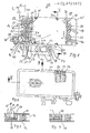
- Fig. 1 eine Seitenansicht einer Zenerbarriere, mit teilweise weggebrochenem Deckel,
- Fig. 2 eine weitere Seitenansicht der Zenerbarriere gemäß der Fig. 1, von der in Fig. 1 in der rückwärtigen Seite gesehen,
- Fig. 3 eine Schnittansicht gemäß der Linie III-III vor dem Ausgießen,
- Fig. 4 eine Schnittansicht gemäß der Linie III-III nach dem Ausgießen,
- Fig. 5 eine Schnittansicht gemäß der Linie V-V der Fig.1,
- Fig. 6-8 drei Aufsichten auf drei nebeneinander angeordnete Zenerbarrieren mit unterschiedlichen Anschlüssen der Potentialausgleichsschiene,
- Fig. 9 eine Aufsicht auf zwei an einer Wand befestigte Zenerbarrieren.
- 1 is a side view of a Zener barrier, with the cover partially broken away,
- 2 shows a further side view of the Zener barrier according to FIG. 1, seen from the rear side in FIG. 1,
- 3 is a sectional view taken along the line III-III before pouring,
- 4 is a sectional view along the line III-III after pouring,
- 5 is a sectional view taken along the line VV of Figure 1,
- 6-8 three views of three zener barriers arranged next to one another with different connections of the equipotential bonding bar,
- Fig. 9 is a plan view of two Zener barriers attached to a wall.
Wie aus der Fig. 1 und insbesondere auch aus der Fig. 5 hervorgeht, weist die erfindungsgemäße Zenerbarriere, die insgesamt mit der Bezugsziffer 10 bezeichnet ist, ein schalenförmig ausgebildetes Gehäuseteil 11 und einen Deckel 12 auf. Das schalenförmig ausgebildete Gehäuseteil 11 ist im Grundriß rechteckförmig und in Schmalbauweise ausgebildet, wobei das Gehäuseteil 11 nach einer Seite hin offen, wie aus Fig. 5 ersichtlich, und auf dieser Seite mittels des Deckels 12 verschlossen ist.As can be seen from FIG. 1 and in particular also from FIG. 5, the zener barrier according to the invention, which is designated overall by
Das Gehäuseteil 11 nimmt eine Platine 13 auf, die die einzelnen Schaltungselemente der Schaltungsanordnung für die eigensichere Zenerbarriere trägt. Von diesen Bauelementen ist lediglich eine Sicherung 14 in der Zeichnung Fig. 5 zu sehen.The
Der Gehäuseboden besitzt einen badewannenförmigen Einzug 15, der zwei in Abstand zueinander angeordnete Öffnung 16 und 17 aufweist, durch die an der Platine 13 befestigte Stifte 18 und 19 nach dem Einsetzen der Platine 13 hindurchgreifen und zwar soweit, daß sie die äußere Seitenfläche 20 des Gehäuseteiles 11 überragen. Diese Stifte 18 und 19 sind Prüfstifte, mit denen die elektrische Prüfung der Schaltungsanordnung erfolgen kann.The housing base has a bath-shaped
Mit der Platine 13 über U-förmige Anschlußbügel 21 verbunden ist die Anschlußfahne 22 einer Anschlußklemme 23, mittels der ein Anschlußleiter 24 mit der Schaltungsanordnung verbunden werden kann. Die Zenerbarriere besitzt insgesamt vier Klemmen 23, 25, 26 und 27, deren Anschlußfahnen 28, 29 und 30 über dem U-Bügel 21 ähnliche U-Bügel 31 (nur der U-Bügel 31 der Anschlußklemme 25 ist zu sehen) mit der Platine verbunden sind. Die Anschlußfahnen 22, 28, 29 und 30 besitzen Durchzüge, von denen lediglich der Durchzug 32 der Anschlußfahne 28 bezeichnet ist, die ein Innengewinde aufweisen, durch das die Klemmschrauben 23, 25, 26 und 27 an den Anschlußfahnen festgeschraubt werden können.With the
Man erkennt aus der Fig. 1 und auch sehr gut aus den Figuren 3 und 4, daß die Bodenebene, die den Einzug 15 aufweist, an den beiden Schmalseiten Verlängerungen 34 und 35, die die Klemmen überdecken und auf dieser Seite den Klemmenaufnahmeraum begrenzen. Der Deckel 12 ist in seiner Außenkontur der Kontur des Gehäuseteiles 11 mit den Verlängerungen 34 und 35 angepaßt, so daß der Deckel 12 den Klemmenaufnahmeraum auf der anderen Seite begrenzt. Nach innen, also ins Innere des Gehäuseteiles 11 wird jeder Klemmenaufnahmeraum durch je eine Begrenzungswand 37 und 28 begrenzt, die gleichzeitig die Trenn- bzw. Dichtungswand für das Gießharz 39, mit dem das Gehäuse ausgegossen ist, bildet.It can be seen from FIG. 1 and also very well from FIGS. 3 and 4 that the floor level, which has the
Man erkennt aus der Fig. 1 insbesondere, daß an dieser Begrenzungswand zusätzlich Trennwände 40 bzw. 41 anschließen, die die Klemmschrauben umgeben und so mit den Begrenzungswänden 37 und 38 je einen Aufnahmeraum 42 bzw. 43 für die Klemmschrauben 23 und 25 bilden, dergestalt, daß der Winkel der Längsachse L jeder Klemmschraube bezogen auf die längere Schmalseitenkante, der mit Alpha bezeichnet ist, spitzt ist, so daß die vier Klemmschrauben 23 bis 27 von oben, also von Pfeilrichtung 0 gesehen, betätigt werden können. Die Trennwände dienen dazu, die Kriechstrecken, die in der Fig. 1 punktiert dargestellt und mit der Bezugsziffer 44 bezeichnet sind ausreichend groß zu machen.It can be seen from FIG. 1 in particular that additional partition walls 40 and 41 connect to this boundary wall, which surround the clamping screws and thus each form a
Im Bereich der unteren Schmalseitenkante, die durch eine Bodenabschlußwand 45 gebildet ist, ist eine Potentialausgleichsschiene 46 eingelegt, die sich nach innen in einen dem U-förmigen Bügel 31 entsprechenden U-förmigen Bügel 47 fortsetzt, wobei die Potentialausgleichsschiene mit dem U-förmigen Bügel 47 mit der Platine bzw. mit den elektrischen Bauelementen der Schaltungsanordnung der Platine 13 verbunden wird. Am äußeren Ende der Potentialausgleichsschiene 46 ist eine Klemmschraube 48 angebracht.There is a potential in the area of the lower narrow side edge, which is formed by a
An der Außenfläche der Bodenwand 45 sind insgesamt vier Vorsprünge 49, 50, 51 und 52 angeformt. Der Vorsprung 49, auch erste Ausformung 49 genannt besitzt eine nach innen weisende Nase 53, der eine nach innen weisende, zu der Nase 53 hinweisende Nase 54 entspricht. Die vierte Ausformung 50 besitzt eine erste Auflageebene 55, die in unmittelbarer Nähe zur Nase 53 liegt, und in gleicher Weise besitzt die dritte Ausformung 51 eine Auflagefläche 56, die im Bereich der Nase 54 liegt. Man erkennt, daß die beiden Nasen 53 und 54 zusammen mit den Auflageflächen 55 und 56 zur Halterung der freien Schenkelenden einer Hut-Profilschiene 57 dienen.A total of four
Die Nase 54 wird dadurch gebildet, daß an einen Bereich 58, der senkrecht zur Bodenwand 45 verläuft, sich ein V-förmiger Bereich 59 anschließt, dessen Spitze die Nase 54 bildet und dessen offene Seite in eine Richtung weist, die parallel zur Bodenwand verläuft.The
Am dritten Vorsprung 51 ist eine Nut 60 angeformt, die mit der offenen V-Seite der zweiten Ausformung 52 zur Aufnahme der Schenkelenden einer C-Profilschiene zusammenwirkt. Die vierte Ausformung 50 besitzt zusätzlich zur Auflagefläche 55 eine weitere Auflagefläche 62, gegen die der eine Schenkel der Tragschiene 61 zum Anliegen kommt.A
Die erste und dritte Ausformung 49 und 51 sind verhältnismäßig starr ausgebildet, wogegen die zweite Ausformung 52 federnd elastisch ausgebildet ist, so daß die Zenerbarriere bzw. das Gehäuse auf den beiden Tragschienen festgeschnappt werden kann.The first and
Der Deckel 12 besitzt mehrere Vorsprünge 63, 64, 65, 66 und 67; mit den Vorsprüngen 64 bis 67 kann der Deckel am Gehäuseteil 11 festgerastet werden; die beiden Vorsprünge 63, von denen lediglich der in der Fig. 1 rechts liegende Vorsprung zu sehen ist, sind bügelförmig ausgebildet und dringen ins Innere des Gießharzes 39 ein, so daß das Gießharz die Vorsprünge vollständig umgibt und dadurch den Deckel formschlüssig festhält.The
Die Montage der Zenerbarriere bzw. der Zusammenbau verläuft wie folgt:
- Zunächst wird in die offene Breitseite des Gehäuseteils 11 die Platine 13 eingelegt, wobei die Platine auf in der Zeichnung nicht näher dargestellten Gehäusevorsprüngen
am Gehäuseteil 11 sowie auf Erweiterungen anden Bügeln Die Bügel 21 liegen zur weiteren Abstützung auf der Innenfläche der Seitenwand auf, wie in Fig. 5bei dem Bügel 21 deutlich zu sehen ist. Dabei greifen die mit der Platine verbundenen Stifte 18 und 19 durch die beiden Öffnungen 16 und 17 hindurch. Danachwird das Gehäuseteil 11 mit der eingesetzten Platine ausgegossen und der Deckel aufgesetzt, bevor das Gießharz ausgehärtet ist. Es besteht natürlich auch die Möglichkeit, ein Loch 70 im Deckel vorzusehen, durch welches nach Aufschnappen des Deckels anden Aufschnappstellen 64 bis 67 das Gießharz eingegossen werden kann. Nach Aushärten des Gießharzes wird über die beiden Anschlußstifte 18 und 19 die Schaltungsanordnung der Zenerbarriere geprüft, die Stifte 18 und 19 werden, wie aus Fig. 4 ersichtlich ist umgebogen, wobei darauf zu achten ist, daß die beiden Stifte 18 und 19 in elektrisch leitender Verbindung miteinander sind und danach wird der Einzug 15mit Gießharz 71 zugegossen.Die Zenerbarriere 10 wird also geprüft, nachdem die Zenerbarriere fertig vergossen und fertig ausgebildet ist.
- First, the
circuit board 13 is inserted into the open broad side of thehousing part 11, the circuit board resting on housing projections (not shown in the drawing) on thehousing part 11 and on extensions on thebrackets brackets 21 rest on the inner surface of the side wall for further support, as can be clearly seen in thebracket 21 in FIG. 5. The pins 18 and 19 connected to the circuit board reach through the twoopenings 16 and 17. Then thehousing part 11 is poured out with the board used and the cover is placed on it before the casting resin has hardened. Of course, there is also the possibility of providing a hole 70 in the cover through which the casting resin can be poured in at the snap-onpoints 64 to 67 after the cover has been snapped on. After the casting resin has hardened, the circuit arrangement of the two pins 18 and 19 Zener barrier tested, the pins 18 and 19 are bent, as can be seen from Fig. 4, taking care that the two pins 18 and 19 are in electrically conductive connection with each other and then thefeed 15 is cast withresin 71. TheZener barrier 10 is therefore checked after the Zener barrier has been cast and finished.
Nachzutragen ist noch, daß auf der der Bodenfläche bzw. der Bodenwand 45 gegenüberliegenden Stirnwand 71 eine Öffnung 72 vorgesehen ist, an die sich ein Führungsring 73 anschließt bzw. von der Öffnung 72 umgeben ist, welcher Führungsring 73 auf einem verstellbarem Schaltelement 74 aufliegt. Der Führungsring 73 dient zum Abdichten desjenigen Teiles des verstellbaren Schaltelementes, das von außen nach Zusammenbau der Zenerbarriere betätigt werden muß, damit die Justiereinrichtung von außen zugänglich bleibt.It must also be added that an
Die Figuren 6 bis 8 zeigen nun unterschiedliche Zusammenschaltungen der Potentialschiene mehrerer Zenerbarrieren. Man erkennt auf einer Hut-Profiltragschiene 80, die der Hut-Profiltragschiene 57 der Fig. 1 entspricht, drei nebeneinander aufgeschnappte Zenerbarrieren 81, 82 und 83. Die Anschlußklemmen 84 bis 86 sind mittels einer Stromsammelschiene 87 gekuppelt, an derem einen Ende eine Anschlußklemme 88 für einen Anschlußleiter 89 angeformt bzw. Befestigt ist.Figures 6 to 8 now show different interconnections of the potential rail of several Zener barriers. On a top-
Bei der Ausgestaltung der Fig. 7 werden die einzelnen Anschlußklemmen 84 bis 86 mittels U-förmig gebogener Leiteranschlußstücke 90 und 91 miteinander verbunden, wogegen in der Ausgestaltung der Fig. 8 an die einzelnen Anschlußklemmen 84 bis 86 Anschlußleiter 92 bis 94 angeschlossen sind, die miteinander mittels einer Verbindungsklemme 95 verbunden sind. An diese Verbindungsklemme 95 kann dann ein weiterer Anschluß- oder Erdungsleiter angeschlossen werden.7, the
Claims (11)
Applications Claiming Priority (2)
| Application Number | Priority Date | Filing Date | Title |
|---|---|---|---|
| DE19833312081 DE3312081A1 (en) | 1983-04-02 | 1983-04-02 | ZENER BARRIER |
| DE3312081 | 1983-04-02 |
Publications (2)
| Publication Number | Publication Date |
|---|---|
| EP0123872A1 true EP0123872A1 (en) | 1984-11-07 |
| EP0123872B1 EP0123872B1 (en) | 1986-12-30 |
Family
ID=6195392
Family Applications (1)
| Application Number | Title | Priority Date | Filing Date |
|---|---|---|---|
| EP84103101A Expired EP0123872B1 (en) | 1983-04-02 | 1984-03-21 | Zener diode barrier |
Country Status (4)
| Country | Link |
|---|---|
| US (1) | US4647141A (en) |
| EP (1) | EP0123872B1 (en) |
| JP (1) | JPS59229848A (en) |
| DE (2) | DE3312081A1 (en) |
Cited By (1)
| Publication number | Priority date | Publication date | Assignee | Title |
|---|---|---|---|---|
| EP0221278A1 (en) * | 1985-10-17 | 1987-05-13 | Inventio Ag | Support for printed circuits arranged in a rack |
Families Citing this family (10)
| Publication number | Priority date | Publication date | Assignee | Title |
|---|---|---|---|---|
| DE3571177D1 (en) * | 1985-11-09 | 1989-07-27 | Weidmueller C A Gmbh Co | INITIATOR TERMINAL BLOCK |
| US4921450A (en) * | 1989-03-16 | 1990-05-01 | Cooper Industries, Inc. | Space saving multipole fuse block |
| DE4015689C2 (en) * | 1990-05-16 | 1994-03-10 | Elco Europ Gmbh | Device for holding electrotechnical, in particular communications technology components |
| US5090922A (en) * | 1990-12-20 | 1992-02-25 | Square D Company | Terminal block with multiple track mounting capability |
| US5480310A (en) * | 1993-10-28 | 1996-01-02 | Raychem Corporation | Connector ground clip |
| DE69414364T2 (en) * | 1994-02-14 | 1999-05-06 | Delco Electronics Corp | Connection plate arrangement for linear dual switching module |
| US5895974A (en) * | 1998-04-06 | 1999-04-20 | Delco Electronics Corp. | Durable substrate subassembly for transistor switch module |
| US6127727A (en) * | 1998-04-06 | 2000-10-03 | Delco Electronics Corp. | Semiconductor substrate subassembly with alignment and stress relief features |
| DE102012218463A1 (en) * | 2012-10-10 | 2014-04-10 | Brose Fahrzeugteile Gmbh & Co. Kommanditgesellschaft, Hallstadt | Method for manufacturing electronic module, involves penetrating fixing portion into not yet hardened casting portion, so that housing cover is fixed after hardening of casting portion to housing, over the casting portion |
| DE202015100696U1 (en) * | 2015-02-12 | 2016-05-13 | Weidmüller Interface GmbH & Co. KG | Arrangement of several locking feet for an assembly and assembly |
Citations (4)
| Publication number | Priority date | Publication date | Assignee | Title |
|---|---|---|---|---|
| DE2753145A1 (en) * | 1977-11-29 | 1979-06-07 | Bosch Gmbh Robert | ELECTRONIC CONTROL UNIT, IN PARTICULAR FOR MOUNTING ON THE ENGINE BLOCK OF MOTOR VEHICLES |
| DE2942258A1 (en) * | 1979-10-19 | 1981-05-07 | Robert Bosch Gmbh, 7000 Stuttgart | ELECTRICAL DEVICE, PREFERABLY RELAY FOR MOTOR VEHICLES |
| DE3037783A1 (en) * | 1980-10-07 | 1982-04-08 | Barlian Reinhold | Zener barrier - has fire-proof insulating casing container holder for retaining parts arranged in given way |
| DE3120583A1 (en) * | 1981-05-23 | 1982-12-09 | F. Wieland, Elektrische Industrie GmbH, 8600 Bamberg | Mounting base for installation apparatuses, especially for switching installation terminal blocks |
Family Cites Families (8)
| Publication number | Priority date | Publication date | Assignee | Title |
|---|---|---|---|---|
| US3579046A (en) * | 1969-05-02 | 1971-05-18 | Jordan Controls Inc | Electrical housing assembly having a plurality of chambers with adjacent circuit board elements |
| DE2312798A1 (en) * | 1973-03-15 | 1974-09-19 | Controlmatic Ges Fuer Ind Auto | SWITCHING AMPLIFIER FOR CONTACTS AND INITIATORS IN TERMINAL BOX |
| DE2554747A1 (en) * | 1975-12-05 | 1977-06-16 | Bosch Gmbh Robert | ELECTRONIC CONTROL UNIT |
| DE2646616C3 (en) * | 1976-10-15 | 1980-08-07 | C. A. Weidmueller Kg, 4930 Detmold | Add-on part that can be lined up |
| DE2714826B2 (en) * | 1977-04-02 | 1980-01-03 | Elrest Elektronik-Regel-Steuertechnik Franz Schauer, 7441 Zizishausen | Housing made of insulating material for accommodating electrical circuit parts |
| FR2440631A1 (en) * | 1978-11-06 | 1980-05-30 | Alsthom Cgee | LOCKING DEVICE FOR FIXING A TERMINAL BLOCK |
| US4218724A (en) * | 1978-11-21 | 1980-08-19 | Kaufman Lance R | Compact circuit package having improved circuit connectors |
| FR2532811B1 (en) * | 1982-09-08 | 1986-12-26 | Legrand Sa | COMPONENT HOLDER (S) |
-
1983
- 1983-04-02 DE DE19833312081 patent/DE3312081A1/en active Granted
-
1984
- 1984-03-21 EP EP84103101A patent/EP0123872B1/en not_active Expired
- 1984-03-21 DE DE8484103101T patent/DE3461885D1/en not_active Expired
- 1984-03-30 JP JP59063092A patent/JPS59229848A/en active Pending
- 1984-04-02 US US06/596,089 patent/US4647141A/en not_active Expired - Fee Related
Patent Citations (4)
| Publication number | Priority date | Publication date | Assignee | Title |
|---|---|---|---|---|
| DE2753145A1 (en) * | 1977-11-29 | 1979-06-07 | Bosch Gmbh Robert | ELECTRONIC CONTROL UNIT, IN PARTICULAR FOR MOUNTING ON THE ENGINE BLOCK OF MOTOR VEHICLES |
| DE2942258A1 (en) * | 1979-10-19 | 1981-05-07 | Robert Bosch Gmbh, 7000 Stuttgart | ELECTRICAL DEVICE, PREFERABLY RELAY FOR MOTOR VEHICLES |
| DE3037783A1 (en) * | 1980-10-07 | 1982-04-08 | Barlian Reinhold | Zener barrier - has fire-proof insulating casing container holder for retaining parts arranged in given way |
| DE3120583A1 (en) * | 1981-05-23 | 1982-12-09 | F. Wieland, Elektrische Industrie GmbH, 8600 Bamberg | Mounting base for installation apparatuses, especially for switching installation terminal blocks |
Cited By (1)
| Publication number | Priority date | Publication date | Assignee | Title |
|---|---|---|---|---|
| EP0221278A1 (en) * | 1985-10-17 | 1987-05-13 | Inventio Ag | Support for printed circuits arranged in a rack |
Also Published As
| Publication number | Publication date |
|---|---|
| EP0123872B1 (en) | 1986-12-30 |
| JPS59229848A (en) | 1984-12-24 |
| DE3312081C2 (en) | 1987-01-08 |
| DE3312081A1 (en) | 1984-10-11 |
| US4647141A (en) | 1987-03-03 |
| DE3461885D1 (en) | 1987-02-05 |
Similar Documents
| Publication | Publication Date | Title |
|---|---|---|
| EP2018646B1 (en) | Switching device, in particular fused interrupters | |
| DE102005009856B4 (en) | Connection or device adapter | |
| DE2639642A1 (en) | CONNECTION CONTACT ARRANGEMENT WITH CLAMPING CONTACT PIECES | |
| EP0379662B1 (en) | Socket block | |
| EP0123872B1 (en) | Zener diode barrier | |
| EP0982978B1 (en) | Housing, in particular lock housing with electrical interconnections | |
| EP0793243A1 (en) | Transformer | |
| DE102011112120B4 (en) | Device with several block terminals | |
| DE19918842B4 (en) | Hunt connection for electr. distribution systems | |
| EP0051755A1 (en) | Protective cover for terminals of electrical appliances | |
| DE3238483A1 (en) | Busbar system | |
| EP0262554B1 (en) | Device for the connection of installation apparatuses to the current bus-bars of a basic bus-bar system | |
| DE2601849C2 (en) | Series disconnect terminal | |
| DE3407991C2 (en) | ||
| EP0568899B1 (en) | Multipole cable plug | |
| DE19751705C2 (en) | Locked mounting block | |
| DE3829421C2 (en) | ||
| DE10125941B4 (en) | Compact arrangement for multi-pole surge current proof surge arresters | |
| EP1868265B1 (en) | Lead connection for a clamp fitted on a top hat rail | |
| EP0980125A1 (en) | Multiphase power busbar | |
| DE3924032C1 (en) | Switch for opening and closing electrical circuits or lines - has fastening clamps for electrical conductors and housing for switch insert | |
| EP0403666B1 (en) | Electrically shielded in-line terminal assembly | |
| DE1765056A1 (en) | Connection rail for the supply of consumers with electricity | |
| EP0675583B1 (en) | Arrangement for wall mounting of an electrical device such as switch, outlet or similar | |
| DE3418665C2 (en) |
Legal Events
| Date | Code | Title | Description |
|---|---|---|---|
| PUAI | Public reference made under article 153(3) epc to a published international application that has entered the european phase |
Free format text: ORIGINAL CODE: 0009012 |
|
| AK | Designated contracting states |
Designated state(s): CH DE FR GB LI NL |
|
| 17P | Request for examination filed |
Effective date: 19840921 |
|
| GRAA | (expected) grant |
Free format text: ORIGINAL CODE: 0009210 |
|
| AK | Designated contracting states |
Kind code of ref document: B1 Designated state(s): CH DE FR GB LI NL |
|
| REF | Corresponds to: |
Ref document number: 3461885 Country of ref document: DE Date of ref document: 19870205 |
|
| ET | Fr: translation filed | ||
| PLBE | No opposition filed within time limit |
Free format text: ORIGINAL CODE: 0009261 |
|
| STAA | Information on the status of an ep patent application or granted ep patent |
Free format text: STATUS: NO OPPOSITION FILED WITHIN TIME LIMIT |
|
| 26N | No opposition filed | ||
| PGFP | Annual fee paid to national office [announced via postgrant information from national office to epo] |
Ref country code: CH Payment date: 19910222 Year of fee payment: 8 |
|
| PG25 | Lapsed in a contracting state [announced via postgrant information from national office to epo] |
Ref country code: LI Effective date: 19920331 Ref country code: CH Effective date: 19920331 |
|
| REG | Reference to a national code |
Ref country code: CH Ref legal event code: PL |
|
| PGFP | Annual fee paid to national office [announced via postgrant information from national office to epo] |
Ref country code: FR Payment date: 19940210 Year of fee payment: 11 |
|
| PGFP | Annual fee paid to national office [announced via postgrant information from national office to epo] |
Ref country code: GB Payment date: 19940214 Year of fee payment: 11 |
|
| PGFP | Annual fee paid to national office [announced via postgrant information from national office to epo] |
Ref country code: NL Payment date: 19940331 Year of fee payment: 11 |
|
| PGFP | Annual fee paid to national office [announced via postgrant information from national office to epo] |
Ref country code: DE Payment date: 19940408 Year of fee payment: 11 |
|
| PG25 | Lapsed in a contracting state [announced via postgrant information from national office to epo] |
Ref country code: GB Effective date: 19950321 |
|
| PG25 | Lapsed in a contracting state [announced via postgrant information from national office to epo] |
Ref country code: NL Effective date: 19951001 |
|
| GBPC | Gb: european patent ceased through non-payment of renewal fee |
Effective date: 19950321 |
|
| PG25 | Lapsed in a contracting state [announced via postgrant information from national office to epo] |
Ref country code: FR Free format text: LAPSE BECAUSE OF NON-PAYMENT OF DUE FEES Effective date: 19951130 |
|
| NLV4 | Nl: lapsed or anulled due to non-payment of the annual fee |
Effective date: 19951001 |
|
| PG25 | Lapsed in a contracting state [announced via postgrant information from national office to epo] |
Ref country code: DE Effective date: 19951201 |
|
| REG | Reference to a national code |
Ref country code: FR Ref legal event code: ST |