EP1068986B1 - Verstellbarer Drehgelenkbeschlag für neigungsverstellbare Sitze - Google Patents
Verstellbarer Drehgelenkbeschlag für neigungsverstellbare Sitze Download PDFInfo
- Publication number
- EP1068986B1 EP1068986B1 EP00122628A EP00122628A EP1068986B1 EP 1068986 B1 EP1068986 B1 EP 1068986B1 EP 00122628 A EP00122628 A EP 00122628A EP 00122628 A EP00122628 A EP 00122628A EP 1068986 B1 EP1068986 B1 EP 1068986B1
- Authority
- EP
- European Patent Office
- Prior art keywords
- hinge member
- bearing plate
- internal teeth
- axle
- seat recliner
- Prior art date
- Legal status (The legal status is an assumption and is not a legal conclusion. Google has not performed a legal analysis and makes no representation as to the accuracy of the status listed.)
- Expired - Lifetime
Links
Images


Classifications
-
- B—PERFORMING OPERATIONS; TRANSPORTING
- B60—VEHICLES IN GENERAL
- B60N—SEATS SPECIALLY ADAPTED FOR VEHICLES; VEHICLE PASSENGER ACCOMMODATION NOT OTHERWISE PROVIDED FOR
- B60N2/00—Seats specially adapted for vehicles; Arrangement or mounting of seats in vehicles
- B60N2/02—Seats specially adapted for vehicles; Arrangement or mounting of seats in vehicles the seat or part thereof being movable, e.g. adjustable
- B60N2/20—Seats specially adapted for vehicles; Arrangement or mounting of seats in vehicles the seat or part thereof being movable, e.g. adjustable the back-rest being tiltable, e.g. to permit easy access
-
- B—PERFORMING OPERATIONS; TRANSPORTING
- B60—VEHICLES IN GENERAL
- B60N—SEATS SPECIALLY ADAPTED FOR VEHICLES; VEHICLE PASSENGER ACCOMMODATION NOT OTHERWISE PROVIDED FOR
- B60N2/00—Seats specially adapted for vehicles; Arrangement or mounting of seats in vehicles
- B60N2/02—Seats specially adapted for vehicles; Arrangement or mounting of seats in vehicles the seat or part thereof being movable, e.g. adjustable
- B60N2/22—Seats specially adapted for vehicles; Arrangement or mounting of seats in vehicles the seat or part thereof being movable, e.g. adjustable the back-rest being adjustable
- B60N2/235—Seats specially adapted for vehicles; Arrangement or mounting of seats in vehicles the seat or part thereof being movable, e.g. adjustable the back-rest being adjustable by gear-pawl type mechanisms
- B60N2/2356—Seats specially adapted for vehicles; Arrangement or mounting of seats in vehicles the seat or part thereof being movable, e.g. adjustable the back-rest being adjustable by gear-pawl type mechanisms with internal pawls
- B60N2/236—Seats specially adapted for vehicles; Arrangement or mounting of seats in vehicles the seat or part thereof being movable, e.g. adjustable the back-rest being adjustable by gear-pawl type mechanisms with internal pawls linearly movable
-
- Y—GENERAL TAGGING OF NEW TECHNOLOGICAL DEVELOPMENTS; GENERAL TAGGING OF CROSS-SECTIONAL TECHNOLOGIES SPANNING OVER SEVERAL SECTIONS OF THE IPC; TECHNICAL SUBJECTS COVERED BY FORMER USPC CROSS-REFERENCE ART COLLECTIONS [XRACs] AND DIGESTS
- Y10—TECHNICAL SUBJECTS COVERED BY FORMER USPC
- Y10T—TECHNICAL SUBJECTS COVERED BY FORMER US CLASSIFICATION
- Y10T29/00—Metal working
- Y10T29/49—Method of mechanical manufacture
- Y10T29/49462—Gear making
- Y10T29/49467—Gear shaping
- Y10T29/49472—Punching or stamping
-
- Y—GENERAL TAGGING OF NEW TECHNOLOGICAL DEVELOPMENTS; GENERAL TAGGING OF CROSS-SECTIONAL TECHNOLOGIES SPANNING OVER SEVERAL SECTIONS OF THE IPC; TECHNICAL SUBJECTS COVERED BY FORMER USPC CROSS-REFERENCE ART COLLECTIONS [XRACs] AND DIGESTS
- Y10—TECHNICAL SUBJECTS COVERED BY FORMER USPC
- Y10T—TECHNICAL SUBJECTS COVERED BY FORMER US CLASSIFICATION
- Y10T29/00—Metal working
- Y10T29/49—Method of mechanical manufacture
- Y10T29/49462—Gear making
- Y10T29/49467—Gear shaping
- Y10T29/49474—Die-press shaping
Definitions
- the present invention relates to an adjustable hinge mount for seats having an adjustable seat back.
- DE 44 41 159 A describes a seat recliner according to the preamble of claim 1.
- This seat comprises a seat back the inclination of which can be adjusted relative to a seat proper or seat frame.
- the known mechanism has particular drawbacks in that. with a certain time of use, because of the design of the hinge and also because of vibrations to the vehicle, clearances are formed in the toothing of the members provided for locking the seat back with respect to the seat proper. Therefore, the safety is not properly ensured and the seat back is not rigidly fixed and therefore provide a bad impression for the seat occupant.
- a seat recliner comprising:
- the adjustable hinge mount is designed for use in connection with a vehicle seat having a reclinable seat back.
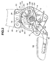
- the hinge mount includes a hinge member 10 connectable to a lateral side of the seat proper and a hinge member 12 connectable to a lateral side of the reclinable seat back at a frame 14 thereof as illustrated by the phantom line in Fig. 2.
- the two hinge members 10 and 12 are supported on and interconnected by an axle 16.
- a spring 18 is coupled between the hinge members 10 and 12 for pivotably biasing the hinge member 12 in a forward direction about the axle 16.
- a free end of the axle 16 is formed with a hooking slot to secure an inner end of the spring 18.
- a hooking pin 20 of the hinge member 12 is used for supporting an outer end of the spring 18.
- the hinge member 10 has two spaced guide walls 24 and 28 under the arcuate internal teeth 22 for guiding a bearing plate 30 which is formed at the upper part thereof with upper teeth 34 for locking cooperation with the actuate internal teeth 22.
- the bearing plate 30 is cut at the lower part thereof to form a lower surface part 36 and has a front lug 38 projecting from a front face 40 thereof.
- the front lug 38 cooperates with the front face 40 to define a notch 42.
- the bearing plate 30 has a rear face 44.
- the front and rear faces 40 and 44, with respect to the forward direction in which the hinge member 12 is biased by the spring 18y are spaced and parallel to each other for slidable cooperation with the guide walls 24 and 28, respectively.
- the slope 36 of the bearing plate 30 rests on an elevated portion 46 of a cam 48 which is pivotably supported on the axle 16.
- the cam 48 is connected to one end of a lever 50 pivotably mounted to the axle 16 for a unitary motion with the lever 50. This connection is accomplished by press fit into a hole 52 of an emboss 54 of the lever 50.
- the front part of the lever 50 carries a handle 56 as illustrated by a phantom line in Fig. 2.
- the lever 50 is biased counterclockwise viewing in Fig. 2 to the position illustrated in Fig. 2 by means of a return spring 58 having one end fixedly anchored to a hooking arm 60 of the lever 50 and an opposite end fixedly anchored to a hooking pin 62 of the hinge member 10.
- the cam 48 has a nose 64 which cooperates with the notch 42 of the bearing plate 30 for disengaging the upper teeth 34 from the internal teeth 22.
- the axle 16 has a flange 66 slidably abutting on the flange member 12 and a non-circular part 68 provided with two opposite flat surfaces. This part 68 is spaced from the flange 66 and disposed in the corresponding non-circular opening 70 of the hinge member 10.
- the axle 16 is non-rotatably fixed to the hinge member 10 by bending a portion adjacent the non-circular part 68 of the hinge member 10 (see Fig. 3).
- the axle 16 has a reduced diameter portion 72 projecting from the non-circular part 68 outwardly of the hinge member 10.
- the hinge member 12 is fixed to the frame 14 of the seat back together with a holder 74 by at least two, preferably, three set pins 76.
- the holder 74 therefore, is fixed to the hinge member 10 with an upper actuate edge 76 of the hinge member 10 interposed between the holder 74 and the hinge member 12, holding the hinge member 10 against the hinge member 12.
- This arrangement ensures engagement of the upper teeth 34 with the internal teeth 22.
- the upper arcuate edge 78 is centered on the axle 16 for slidable cooperation with the holder 74 during adjustment of the seat back.
- the holder 74 is in the form of a plate having an impressed lower arcuate marginal portion 80 slidably engaging the first hinge member 10 in the vicinity of the upper arcuate edge 78.
- a plurality of set pins each having an enlarged head on a spacer, constitute a holder.
- each pin 82 has an enlarged head 84 on a spacer 86.
- the spacer 86 serves as a head and abuts on the hinge member 12.
- the enlarged head 84 of each of the pins 80 slidably engages the hinge member 10 in the vicinity of the upper actuate edge 78 during adjustment of the seat back.
- the hinge members 10 and 12 are formed with impressed portions 88 and 90.
- the impressed portion 88 of the hinge member 10 defines on its outer periphery the upper arcuate edge 78.
- the impressed portion 88 partially surrounds a major inner portion 92.
- the major inner portion 92 is not surrounded by the impressed portion 88 at a lower part of the hinge member 10.
- Disposed within this major inner portion 92 is the lever 50.
- the impressed portion 90 of the hinge member 12 is surrounded by a major outer portion 94.
- the major outer portion 94 cooperates with the impressed outer portion 88 for pivotal motion of the hinge member 12 relative to the hinge member 10 about the axle 16.
- Disposed within the impressed inner portion 90 of the hinge member 12 are the bearing plate 30 and the cam 48.
- the major inner portion 92 of the hinge member 10 is recessed from the surrounding impressed portion 88 to receive the lever 50.
- the lever 50 is disposed between the major inner portion 92 of the hinge member 10 and the cam 34.
- the impressed portion 90 of the hinge member 12 is recessed from the surrounding major outer portion 94 to define a recessed portion 96 in which bearing plate 30 and the cam 48 are disposed.
- the impressed portion 88 of the hinge member 10 is provided with the two parallel guide walls 24 and 28 formed by a precision stamping and cold pressing process. The guide walls 24 and 28 extend into the recessed portion 96 for guiding the bearing plate 30.
- the hinge member 12 which is thus disengaged from the hinge member 10 can pivot in a forward direction or in a rearward direction according to the desired adjustment of the seat back.
- the return spring 58 returns the lever 50 to the position as illustrated in Fig. 2, and the nose 64 is separated from the front lug 38 and simultaneously the elevated portion 46 of the cam 48 lifts the bearing plate 30 into firm engagement with the internal teeth 22 of the hinge member 12.
- the guide walls 24 and 28 and the lower surface part 36 of the bearing plate 30 cause the bearing plate 30 to move from the position illustrated by the fully drawn line in Fig. 5 to the position as illustrated by the dashed line in Fig. 2 (or the position as illustrated by the phantom line in Fig. 5).
- the lower part of the front lug 38 and the lower surface part 36 of the bearing plate 30 form a double slope having a shape of an inverted V with a large opening.
- the cam 48 pushes the bearing plate 30 perfectly into firm locking engagement with the internal teeth 22, and therefore the hinge member 12 is perfectly fixed with the hinge member 10, thereby providing a perfect locking of the seat back with respect to the sitting position of the seat in consideration.
- the bearing plate 30 can use substantially the whole thickness of the upper teeth 34 for engagement with the internal teeth 22 since the guide walls 24 and 28 are disposed in the recessed portion 96 where the internal teeth 22 are disposed. This results in a reduction in thickness of the bearing plate 30 and thus the thickness of the upper teeth 34, providing advantage in weight and manufacturing cost.
- the bearing plate 30 is disposed above the axle 16 within a triangle-like area having one corner thereof on the axle 16 and the other two corners thereof on the remotest two mount holes receiving the set pins 76. Within this area, the upper teeth 34 are brought into and out of engagement with the internal teeth 22.
- the beating plate 30 is disposed above the axle 16 within a sector-like area centering on the axle 16 and defined by the periphery of the lower arcuate portion 80 of the holder 74 and the upper teeth 34 are brought into and out of engagement with the internal teeth 22. This provides a rigid structure which can ensure and maintain proper engagement between the upper and internal teeth 34 and 22 during rear-end collision of the vehicle.
- the weight of the seat occupant urges the seat back rearwardly to pull the upper portion of the hinge member 12 above the axle 16 toward the hinge member 10 in such a direction to keep engagement of the upper teeth 34 with the internal teeth 22. If the hinge member 12 is inclined with the upper portion thereof above the axle 16 tending to separate from the hinge member 10, such separation is compensated by action of the holder 74 urging the upper portion of the hinge member 10 to follow the hinge member 12. Thus, the engagement of the upper teeth 34 with the internal teeth 22 can be maintained.
- a motion transmitting pipe 100 is coupled at one end thereof with a projection 102 of the axle 16 and at the opposite end thereof with a similar projection of an axle of the follower hinge mount for rotation with respect to the hinge member 10.
- the pipe 100 has a lateral lug or link 104 projecting therefrom in a radial direction.
- This lug 104 is formed with a hole 106 at a location adjacent a free end thereof.
- the hinge member 10 is formed with an arcuate window or slot 108 centering on the axle 16.
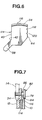
- Fig. 6 illustrates an alternative embodiment to the bearing plate 30.
- the illustrated bearing plate 114 in Fig. 6 is substantially the same as the bearing plate 30.
- the bearing plate 114 is different from the bearing plate 30 in that the bearing plate 114 has a wall portion 116 extending along upper teeth 34 thereof and includes at least one portion recessed inwardly from a rear face 44 thereof.
- the bearing plate 114 is recessed at two portions 118 and 120 inwardly from the rear face 44.
- the rear face 44 of the beating plate 114 provides an increased pressure acting area owing to the wall portion 116 particularly at a portion where the upper teeth 34 are formed.
- the bearing plate 114 can firmly engage with the guide wall 28 deeper than the bearing plate 30 does in the cess of application of force to the bearing plate during rear end collision of the vehicle.
- perfect engagement of the upper teeth 34 with the internal teeth 22 is maintained under more severe circumstance during rear end collision.
- the lateral lug 100 is a separate piece fixedly connected to the pipe 100 for a unitary rotation therewith.
- Figs. 8 and 9 illustrate two modifications of a motion transmitting pipe.
- a motion transmitting pipe 122 has each of one and opposite end portions flattened and bent to form an integral lateral lug 124.
- This lug 124 is formed with a hole 126 for receiving the motion transmitting pin 110 and a hole 128 concentric with the pipe 122 proper for receiving the projection 102 of the axle 16.
- a motion transmitting pipe 130 illustrated in Fig. 9 is substantially the same as the pipe 122 except the provision of a cutout 132 instead of the hole 126 for receiving the motion transmitting pin 110.
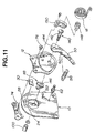
- the lever 50 is disposed between the hinge members 10 and 12. If desired, a lever 50 may be disposed between a hinge member 12 and a flange 134 of an axle 16 as shown in Fig. 10.
- a motion transmitting pin 122 extends through a cam 48 and fixed thereto.
- the lever 50 is formed at one end thereof with a hole 136 receiving the pin 110 extending through an arcuate window 138 with which the hinge member 12 is formed. With this pin 110, the cam 48 is connected to both the lever 50 and a lateral lug 104 of a motion transmitting pipe 110.
- the embodiment illustrated in Fig. 10 is substantially the same as the embodiment illustrated in Figs. 1 to 3.
- the cam 48 and the lever 50 are rotatably supported on the axle and interconnected by the emboss 54 (see Fig. 1) or the motion transmitting pin 110 (see Fig. 9) and, with this pin 110, the cam 48 drives the motion transmitting pipe 100.
- an axle 140 interconnects a lever 50, a cam 48 and a motion transmitting pipe 100 for unitary rotation.
- the axle 140 has a non-circular part 142 provided with two opposite flat surfaces and a free end portion splined.
- the non-circular part 142 is fitted in a non-circular opening 144 of the lever 50 and also in a non-circular opening 146 of the cam 48.
- the motion transmitting pipe 100 is splined at one end thereof to receive the splined free end portion of the axle 140.
- a slotted pin 148 fixed to a hinge member 12 by a bracket 150 is used to anchor or hook an inner end of a spring 18.
- An outer end of the spring 18 is supported on a hooking pin 152 fixed to a hinge member 10.
- Fig. 12 shows a modification of the embodiment of Fig. 11. This modification is different from the embodiment of Fig. 11 in that a lever 50 is disposed between hinge members 10 and 12, only.
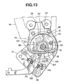
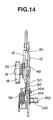
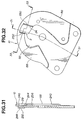
- FIGs. 13 to 16 there is shown a seat recliner using an adjustable hinge mount of the kind described in the preceding in connection with Figs. 1 to 3.
- Figs. 13 and 14 show an adjustable hinge mount at a left hand rear corner of a seat of a vehicle
- Figs. 15 and 16 show a similar adjustable hinge mount at a right hand rear corner of the vehicle seat.
- the adjustable hinge mount of Figs. 13 and 14 is substantially the same as the hinge mount of Figs. 1 to 3.
- the same reference numerals as used in Figs. 1 to 3 are used to denote like or similar parts in Figs. 13 and 14.
- the adjustable hinge mount of Figs. 15 and 16 is substantially the same as the hinge mount of Figs. 13 and 14.
- the same reference numerals as used in Figs. 13 and 14 are used to denote like or similar parts in Figs. 15 and 16 with a suffix A.
- a motion transmitting pipe 100 having at one end a lateral lug 104 and at an opposite end a lateral lug 104A is disposed between a hinge member 10 and a hinge member 10A.
- the hinge members 10 and 10A have second axles 160 and 160A, respectively.
- the second axle 160 is mounted to the hinge member 10 at a location distant downwardly from an axle 16
- the second axle 160A is mounted to the hinge member 10A at a location distant downwardly from an axle 16A.
- the second axles 160 and 160A are aligned and opposed to each other to support the motion transmitting pipe 130 at one and opposite ends thereof.
- the hinge members 10 and 10A are formed with arcuate windows or slots 162 and 162A, respectively.
- a motion transmitting pin 164 is disposed in the arcuate window 162.
- This pin 164 has one end fixedly carried by a lever 50 and an opposite end received in a cutout of the lateral lug 104.
- Another motion transmitting pin 164A is disposed in the arcuate window 162A.
- One end of this pin 164A is fixedly carried by a lever 50A and an opposite end thereof is received in a cutout of the lateral lug 104A. Pivoting the lever 50 causes the lateral lug 104 to turn the pipe 100 through the pin 164, and turning motion of the pipe 100 causes the lateral lug 104A to pivot the lever 50A through the pin 164A.
- a control arrangement employed in this embodiment is slightly different from the control arrangement of the embodiment of Figs. 1 to 3.
- a lever 50 is formed with a clot 170 at one end thereof and a bearing plate 30 has a pin 172 projecting therefrom into the slot 170 for engagement therewith. Pivoting motion of the lever 50 causes the pin 172 to disengage the bearing plate 30 from an internal teeth 22.
- the bearing plate 30 is not formed with a front lug and a cam 48 is not provided with a nose.
- the bearing plate 30 has a lower surface part 36 and the cam 48 has an elevated portion 46 cooperating with the lower surface part 36 for pushing the bearing plate into locking engagement with the internal teeth 22 in substantially the same manner as in the embodiment of Figs. 1 to 3.
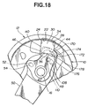
- the bearing plate 30 includes a rear lug 174 projecting from a rear face 44 thereof.
- the rear lug 174 defines a second lower surface part 176 of the bearing plate 30.
- the cam 48 has a second elevated portion 178 for cooperation with the second lower surface part 176 for engaging or supporting the second lower surface part 176 thereby to prevent the bearing plate from moving out of locking engagement with the internal teeth 22 when, with upper teeth 34 in locking engagement with the internal teeth 22, a hinge member 12 is pivotably biased in a rearward direction, during rear end collision of the vehicle.
- the bearing plate 30 is supported at two points B and C when the hinge member 12 is pivoted in the rearward direction E and the force is applied to the bearing plate 30 at a point D of the locking engagement. By supporting the bearing plate at two points B and C, the locking engagement is perfectly maintained.
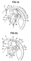
- Fig. 20 illustrates the position of the cam 48 and the bearing plate 30 when the lever 50 is raised or lifted to a released or unlock position.
- the bearing plate 30 includes a front lug 180 projecting from a front face 40 thereof.
- This front lug 180 defines a first lower surface part or slope 182 which is located forwardly of the front face 40.
- a second lower surface part 176 of the bearing plate 30 is located below a rear face 44.
- a cam 48 has a first elevated portion 46 and a second elevated portion 178. The first elevated portion 46 cooperates with the first lower surface part 182 for pushing the bearing plate 30. Pushing through the first lower surface part 182 causes the bearing plate 30 to incline between two guide walls 24 and 28 into contact with the guide walls 24 and 28.
- the bearing plate 30 inclines clockwise viewing in Fig. 21 and an upper edge of the rear face 44 and a lower portion of the front face 40 comes into contact with the guide walls 24 and 28, respectively, to maintain locking engagement of upper teeth 34 with internal teeth 22. Clearances between the front face 40 and the guide wall 24 and between the rear face 44 and the guide wall 28 which are needed for smooth mobility of the beating plate 30 are closed by inclination of the bearing plate 30. There is thus obtained a safe and without clearance locking of the seat back with respect to the proper.
- the second elevated portion 178 is positioned below and near the second lower surface part 176 for cooperation with the second lower surface part 176 for engaging or supporting the bearing plate 30 during rear end collision.
- the bearing plate 30 has a rear lug 184 projecting from the rear face 44 and defining the second lower surface part 176.
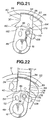
- the illustrated mechanism in Fig. 22 is substantially the same as the mechanism of Figs. 18 to 20. The difference resides in relation of the guide walls 24, 28 with regard to the front and rear faces of the bearing plate 30.
- the guide walls 24 and 28 are parallel to the front and rear faces 40 and 44 of the beating plate 30 when the upper teeth 34 are in locking engagement with the internal teeth 22.
- the spaced parallel guide walls 24 and 28 are inclined by a predetermined degree of one degree (1 degree) in the forward direction with respect to the spaced parallel front and rear faces 40 and 44 of the bearing plate 30.
- the bearing plate 30 engages at two location on the front and rear faces 40 and 44 the inclined guide walls 24 and 28, respectively, when the upper teeth 34 are in locking engagement with the internal teeth 22. For the same reason as described in connection with Fig. 21, a safe and without clearance locking of the seat back with respect to the seat proper is obtained.
- the illustrated embodiment in Figs. 23 and 24 is improved version of the embodiment of Figs. 18 to 20.
- the improvement resides in addition of a third lower surface part 186 adjacent a front face 40 of a bearing plate 30 and addition of at third elevated portion 188 on a cam 48.
- the third elevated portion 188 is arranged for cooperation with the third lower surface part 186 for engaging and supporting (see point H in Fig. 23) the third lower surface part 186 to prevent the bearing plate 30 from moving out of engagement with internal teeth 22 when a hinge member 12 is pivotably biased in a forward direction E.
- Fig. 24 shows the position of bearing plate 30 and the cam 48 in an unlocked or released position.
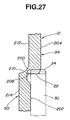
- the hinge member 12 includes the impressed inner portion 90, the major outer portion 94 surrounding the impressed inner portion 90, and a bridge portion 200 (see Fig. 27) connecting the impressed portion 90 to the major outer portion 94.
- An inner surface 202 of the impressed portion 90 is recessed from an inner surface 204 of the major outer portion 94 to cooperate with an inner periphery 206 of the major outer portion 94 to define the recessed portion 96.
- the internal teeth 22 are formed in the inner periphery 206 of the major outer portion 94.
- the bridge portion 200 has a rounded inner transition wall 208 connecting the inner periphery 206 of the major outer portion 94 to the inner surface 202 of the impressed portion 90 at least in the region where the internal teeth 22 are formed.
- the rounded inner transition wall 208 is recessed from the inner surface 202 of the impressed portion 90.
- the bridge portion 200 has a rounded outer transition wall 210 connecting an outer surface 212 of the major outer portion 94 to an outer surface 214 of the impressed portion 90.
- the rounded outer transition wall 210 is recessed toward the rounded inner transition wall 208.
- the rounded outer transition wall 210 connects smoothly to the outer surface 212 of the major outer portion 94.
- the method of manufacturing the impressed portion 90 in the hinge member 12 and providing the impression with the internal teeth 22 includes a preliminary stamping process as shown in Fig. 28 and a precision stamping process simultaneously with a cold pressing as shown in Fig. 29.
- a flat wall is impressed to form the impressed portion 90 surrounded by the inner periphery 206 of the major outer portion 94.
- a special punch 216 with a rounded buldge 218 and a special die 220 with a rounded corner 222 it is possible to increase the structural strength of the bridge portion 200 by forging. Owing to the rounded recess or inner transition wall 208 formed at root of the internal teeth 22, stress concentration can be avoided. Stress concentration at the bridge portion 200 can be avoided due to the rounded inner and outer transition walls 208 and 210.
- the product producing by this process shown in Fig. 30 has a depressed portion 228 along the inner periphery of the major outer portion 94.
- the depressed portion 228 has an inner surface 230 recessed from the inner surface 204 of the major outer portion 941 and connected to the inner periphery 206 by a slope 232.
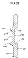
- the hinge member 10 includes the major inner portion 92 and the impressed outer portion 88 partially surrounding the major inner portion 92.
- the impressed portion 88 has an outer surface 240 raised from an outer surface 242 of the major inner portion 92.
- the impressed portion 88 has a depressed section 244 having a surface 246 recessed from the outer surface 240 of the impressed portion 88 to form the two spaced guide walls 24 and 28.
- the depressed section 244 has an opposite surface 248 (see Fig. 33).
- the impressed portion 88 has bridge walls 250 and 252 connecting the opposite surface 248 to the adjacent portions of an inner surface 254 of the impressed portion 88, respectively.
- the bridge walls 250 and 252 extend along the two guide walls 24 and 28, respectively, and elevated from the opposite surface 248 of the depressed section 244 and also from the adjacent portions of the inner surface 254 of the impressed portion 240.
- a thickness of the depressed section 244 is less than a thickness of the impressed portion 88.
- the first mentioned surface 244 of the depressed section 244 is recessed from an outer surface 256 of the major inner portion 92 of the hinge member 10.
- the method of forming two spaced guide walls in a flat wall of the hinge member 10 includes a preliminary stamping process (see Fig. 34) and a precision stamping process with a cold pressing (see Fig. 35).
- a preliminary stamping process an emboss is produced by pressing by using a punch 258 and a die 260.
- the embossed portion is depressed to form the depressed section 244 with the elevated bride walls 250 and 252 on the opposite surface 248 of the depressed section 244.
Landscapes
- Engineering & Computer Science (AREA)
- Aviation & Aerospace Engineering (AREA)
- Transportation (AREA)
- Mechanical Engineering (AREA)
- Chairs For Special Purposes, Such As Reclining Chairs (AREA)
- Seats For Vehicles (AREA)
Claims (15)
- Sitzlehnenverstellvorrichtung, umfassend:ein erstes Scharnierelement (10), welches geeignet ist, an einer Sitzvorrichtung befestigt zu werden;ein zweites Scharnierelement (12), welches geeignet ist, an einer Sitzlehne befestigt zu werden;eine Feder (18), welche zwischen dem ersten und dem zweiten Scharnierelement (10, 12) zum drehgelenkigen Vorspannen des zweiten Scharnierelements (12) in einer Richtung um eine Achse (16) relativ zum ersten Scharnierelement (10) verbunden ist;innere Zähne (22), welche im zweiten Scharnierelement (12) längs einer auf der Achse (16) zentrierten bogenförmigen Fläche ausgebildet sind;eine Lagerplatte (30) mit oberen Zähnen (34) zum feststellenden Zusammenwirken mit den inneren Zähnen (22), wobei die Lagerplatte (30) eine vordere und eine hintere Seite (40, 44) aufweist;in Abstand angeordnete Führungswände (24, 28), welche im ersten Scharnierelement (10) zum gleitfähigen Zusammenwirken mit der vorderen und der hinteren Seite (40, 44) der Lagerplatte ausgebildet sind; undSteuerelemente zum Steuern der Bewegung der Lagerplatte (30) in und außer Eingriff mit den inneren Zähnen (22), wobei die Steuerelemente einen Hebel (50), welcher drehgelenkig mit dem ersten Scharnierelement (10) verbunden ist, und einen Nocken (48) in Einheitsbewegung mit dem Hebel (50) zum Bewegen der oberen Zähne (34) der Lagerplatte (30) in Eingriff mit den inneren Zähnen (22) des zweiten Scharnierelements (12) umfasst;
dadurch gekennzeichnet, dass
die Lagerplatte (30) an zwei unterschiedlichen Bereichen der vorderen und hinteren Seite (44) davon mit den Führungswänden (24, 28) eingreift, um einen feststellenden Eingriff der oberen Zähne (34) mit den inneren Zähne (22) beizubehalten. - Sitzlehnenverstellvorrichtung nach Anspruch 1, dadurch gekennzeichnet, dass die Führungswände (24, 28) in Bezug auf die vordere bzw. hintere Seite der Lagerplatte (30) geneigt sind, wenn die Lagerplatte (30) in einem feststellenden Eingriff mit den inneren Zähnen (22) ist.
- Sitzlehnenverstellvorrichtung nach Anspruch 2, dadurch gekennzeichnet, dass die Führungswände (24, 28) geneigt sind in der einen Richtung um einen vorbestimmten Grad in Bezug auf die vordere bzw. hintere Seite der Lagerplatte (30).
- Sitzlehnenverstellvorrichtung nach Anspruch 3, dadurch gekennzeichnet, dass der vorbestimmte Grad ein Grad ist.
- Sitzlehnenverstellvorrichtung nach Anspruch 1, gekennzeichnet durch eine Einrichtung zur Verhinderung, dass sich die Lagerplatte (30) aus dem feststellenden Eingriff mit den inneren Zähnen (22) bewegt, wenn sich die Lagerplatte (30) in feststellendem Eingriff mit den inneren Zähnen (22) befindet, wobei das zweite Scharnierelement (12) drehgelenkig vorgespannt ist.
- Sitzlehnenverstellvorrichtung nach Anspruch 5, dadurch gekennzeichnet, dass die Einrichtung erste und zweite untere Flächenabschnitte (36, 176) umfasst, ausgebildet auf der Lagerplatte (30), und erste und zweite erhöhte Abschnitte (46, 178), ausgebildet auf dem Nocken (48), wobei die ersten und zweiten unteren Flächenabschnitte (36, 176) mit den ersten und zweiten erhöhten Abschnitten (46, 178) zusammenwirken, um die Lagerplatte (30) an ersten und zweiten Kontaktpunkten (B, C) dazwischen zu lagern.
- Sitzlehnenverstellvorrichtung nach Anspruch 6, dadurch gekennzeichnet, dass die Lagerplatte (30) einen vorderen Vorsprung (180) aufweist, der von der Vorderseite (40) davon hervorsteht, wobei der vordere Vorsprung (180) den ersten unteren Flächenabschnitt (182) definiert, und dass die Lagerplatte (30) gedrängt wird, sich zwischen den Führungswänden (24, 28) zu neigen und in feststellenden Eingriff mit den inneren Zähnen (22) zu gelangen, wenn die Lagerplatte (30) durch den ersten unteren Flächenabschnitt (182) geschoben wird.
- Sitzlehnenverstellvorrichtung nach Anspruch 6, dadurch gekennzeichnet, dass der Hebel (50) einen Schlitz (170) an dem einen Ende davon aufweist und dass die Lagerplatte (30) einen Stift (172) umfasst, welcher in den Schlitz (170) eingreift, wobei der Schlitz (170) und der Stift (172) zusammenwirken, um die Lagerplatte (30) außer Eingriff mit den inneren Zähnen (22) zu bringen, wenn der Hebel (50) gedreht wird.
- Sitzlehnenverstellvorrichtung nach Anspruch 6, dadurch gekennzeichnet, dass der Hebel (50) drehgelenkig um die Achse befestigt ist und dass der Nocken (48) drehgelenkig um die Achse befestigt ist.
- Sitzlehnenverstellvorrichtung nach Anspruch 1, dadurch gekennzeichnet, dass
das zweite Scharnierelement (12) mit mindestens zwei in Abstand angeordneten Befestigungslöchern ausgebildet ist, durch welche das zweite Scharnierelement an der Sitzlehne befestigt ist;
die inneren Zähne (22) innerhalb eines dreieckartigen Bereichs, dessen Ecken auf der Achse und den zwei Befestigungslöchern liegen, angeordnet sind,
die Lagerplatte (30) über der Achse angeordnet ist, und
die inneren Zähne (22) und die oberen Zähne (34) innerhalb des dreieckartigen Bereichs angeordnet sind. - Sitzlehnenverstellvorrichtung nach Anspruch 1, dadurch gekennzeichnet, dass
das erste Scharnierelement (10) eine obere bogenförmige Kante (78), welche auf der Achse zentriert ist, aufweist,
ein Halter (74) am zweiten Scharnierelement befestigt ist, wobei die bogenförmige obere Kante des ersten Scharnierelements zwischen dem Halter und dem zweiten Scharnierelement zum Halten des ersten Scharnierelements gegen das zweite Scharnierelement angeordnet ist,
die Lagerplatte (30) innerhalb eines sektorartigen Bereichs in Zentrierung bezüglich der Achse und definiert durch die bogenförmige obere Kante angeordnet ist, und
die inneren Zähne (22) und die oberen Zähne (34) zum Eingriff und Lösen des Eingriffs innerhalb des sektorartigen Bereichs zusammenwirken. - Sitzlehnenverstellvorrichtung nach Anspruch 11, dadurch gekennzeichnet, dass der Halter (74) in Form einer Platte mit einem geprägten unteren bogenförmigen Randabschnitt (80) in Gleiteingriff mit dem ersten Scharnierelement in der Nähe der bogenförmigen oberen Kante (78) davon vorliegt.
- Sitzlehnenverstellvorrichtung nach Anspruch 6, gekennzeichnet durch
ein Bewegungsübertragungsrohr (100, 122, 130), welches drehbar am ersten Scharnierelement angebracht ist,
wobei das Bewegungsübertragungsrohr (100, 122, 130) einen Vorsprung (104, 124) aufweist, welcher davon in einer Radialrichtung vorsteht;
das erste Scharnierelement, welches mit einem Fenster (108) ausgebildet ist;
einen Bewegungsübertragungsstift (110), welcher im Fenster angeordnet ist, wobei der Bewegungsübertragungsstift an einem Ende davon an dem Nocken befestigt ist und ein gegenüber liegendes Ende aufweist, welches mit dem Vorsprung (104, 124) in antreibendem Eingriff ist. - Sitzlehnenverstellvorrichtung nach Anspruch 13, dadurch gekennzeichnet, dass das Bewegungsübertragungsrohr (100, 122, 130) an dem einen Ende davon drehbar mit der Achse verbunden ist.
- Sitzlehnenverstellvorrichtung nach Anspruch 6, dadurch gekennzeichnet, dass
der Hebel (50) zwischen dem Nocken und dem ersten Scharnierelement angeordnet ist, und
das erste Scharnierelement (10) einen Abschnitt zur Aufnahme des Hebels aufweist.
Applications Claiming Priority (19)
| Application Number | Priority Date | Filing Date | Title |
|---|---|---|---|
| JP15743795 | 1995-06-23 | ||
| JP15743795 | 1995-06-23 | ||
| JP16582195A JP2944468B2 (ja) | 1995-06-30 | 1995-06-30 | シートリクライニング装置 |
| JP16582195 | 1995-06-30 | ||
| JP16582095 | 1995-06-30 | ||
| JP7165820A JP3053354B2 (ja) | 1995-06-30 | 1995-06-30 | シートリクライニング装置 |
| JP7165819A JP3025628B2 (ja) | 1995-06-30 | 1995-06-30 | シートリクライニング装置 |
| JP16581995 | 1995-06-30 | ||
| JP17007995A JP3543872B2 (ja) | 1995-07-06 | 1995-07-06 | シートリクライニング装置のツースプレート及びその製法 |
| JP17007995 | 1995-07-06 | ||
| JP7312206A JPH09149832A (ja) | 1995-11-30 | 1995-11-30 | 内歯式シートリクライニング装置のロック部構造 |
| JP31220695 | 1995-11-30 | ||
| JP33834595 | 1995-12-26 | ||
| JP33834595 | 1995-12-26 | ||
| JP1346496 | 1996-01-30 | ||
| JP01346496A JP3543888B2 (ja) | 1996-01-30 | 1996-01-30 | シートリクライニング装置のベースプレート及びその製法 |
| JP7302496 | 1996-03-28 | ||
| JP8073024A JPH09262150A (ja) | 1996-03-28 | 1996-03-28 | 車両用シートリクライニング装置 |
| EP96110177A EP0749865B1 (de) | 1995-06-23 | 1996-06-24 | Verstellbarer Drehgelenkbeschlag für neigungsverstellbare Sitze |
Related Parent Applications (2)
| Application Number | Title | Priority Date | Filing Date |
|---|---|---|---|
| EP96110177A Division EP0749865B1 (de) | 1995-06-23 | 1996-06-24 | Verstellbarer Drehgelenkbeschlag für neigungsverstellbare Sitze |
| EP96110177.1 Division | 1996-06-24 |
Publications (3)
| Publication Number | Publication Date |
|---|---|
| EP1068986A2 EP1068986A2 (de) | 2001-01-17 |
| EP1068986A3 EP1068986A3 (de) | 2001-01-31 |
| EP1068986B1 true EP1068986B1 (de) | 2003-10-22 |
Family
ID=27576639
Family Applications (3)
| Application Number | Title | Priority Date | Filing Date |
|---|---|---|---|
| EP00122628A Expired - Lifetime EP1068986B1 (de) | 1995-06-23 | 1996-06-24 | Verstellbarer Drehgelenkbeschlag für neigungsverstellbare Sitze |
| EP00122629A Expired - Lifetime EP1068987B1 (de) | 1995-06-23 | 1996-06-24 | Verstellbarer Drehgelenkbeschlag für neigungsverstellbare Sitze |
| EP96110177A Expired - Lifetime EP0749865B1 (de) | 1995-06-23 | 1996-06-24 | Verstellbarer Drehgelenkbeschlag für neigungsverstellbare Sitze |
Family Applications After (2)
| Application Number | Title | Priority Date | Filing Date |
|---|---|---|---|
| EP00122629A Expired - Lifetime EP1068987B1 (de) | 1995-06-23 | 1996-06-24 | Verstellbarer Drehgelenkbeschlag für neigungsverstellbare Sitze |
| EP96110177A Expired - Lifetime EP0749865B1 (de) | 1995-06-23 | 1996-06-24 | Verstellbarer Drehgelenkbeschlag für neigungsverstellbare Sitze |
Country Status (4)
| Country | Link |
|---|---|
| US (2) | US5813724A (de) |
| EP (3) | EP1068986B1 (de) |
| KR (1) | KR100197921B1 (de) |
| DE (3) | DE69633309T2 (de) |
Families Citing this family (31)
| Publication number | Priority date | Publication date | Assignee | Title |
|---|---|---|---|---|
| JP3579236B2 (ja) * | 1997-02-13 | 2004-10-20 | 日本発条株式会社 | リクライニング装置 |
| US6142569A (en) * | 1997-02-13 | 2000-11-07 | Nhk Spring Co., Ltd, | Reclining device |
| JP3578925B2 (ja) * | 1998-11-30 | 2004-10-20 | 富士機工株式会社 | シートリクライニング装置における振動音防止構造 |
| EP1195115B1 (de) * | 1999-06-16 | 2009-12-23 | NHK Spring Co., Ltd. | Neigungsverstellvorrichtung |
| FR2806982B1 (fr) * | 2000-03-30 | 2002-06-14 | Faurecia Sieges Automobile | Mecanisme d'articulation pour siege de vehicule et siege equipe d'un tel mecanisme |
| JP3838003B2 (ja) * | 2000-07-26 | 2006-10-25 | アイシン精機株式会社 | 車両用シートリクライニング装置 |
| JP3804453B2 (ja) | 2001-01-19 | 2006-08-02 | トヨタ紡織株式会社 | リクライニング装置 |
| DE10102860A1 (de) | 2001-01-23 | 2002-08-01 | Keiper Gmbh & Co | Beschlag für einen Fahrzeugsitz |
| JP4433649B2 (ja) | 2001-09-28 | 2010-03-17 | トヨタ紡織株式会社 | フランジを備えた製品の成形方法 |
| JP4277635B2 (ja) * | 2002-10-31 | 2009-06-10 | トヨタ紡織株式会社 | 隙間設定方法及びそれに用いる装置 |
| DE10253054B4 (de) | 2002-11-14 | 2007-01-18 | Keiper Gmbh & Co.Kg | Beschlag für einen Fahrzeugsitz |
| US6910738B2 (en) | 2003-01-28 | 2005-06-28 | Fisher Dynamics Corporation | Device and method for assembling a recliner mechanism |
| US6890034B2 (en) | 2003-01-28 | 2005-05-10 | Fisher Dynamics Corporation | Compact recliner with locking cams |
| US7296456B2 (en) * | 2003-03-26 | 2007-11-20 | Araco Kabushiki Kaisha | Methods and apparatus for manufacturing flanged articles |
| GB2401035B (en) * | 2003-04-29 | 2006-02-08 | Wonderland Nursery Goods | Foldable frame with position locking device for use in a hook-on type baby seat |
| CN100465024C (zh) * | 2004-01-07 | 2009-03-04 | Ifb汽车有限公司 | 用于车辆座椅的双调角器 |
| US20050168034A1 (en) * | 2004-01-21 | 2005-08-04 | Scott Fast | Disc recliner with dual cams |
| US7097253B2 (en) * | 2004-03-11 | 2006-08-29 | Fisher Dynamics Corporation | Round recliner assembly with rear folding latch |
| US7025422B2 (en) * | 2004-03-11 | 2006-04-11 | Fisher Dynamics Corporation | Round recliner assembly with rear folding latch |
| JP4735380B2 (ja) * | 2005-07-01 | 2011-07-27 | トヨタ紡織株式会社 | ワークの製造方法 |
| JP5673571B2 (ja) | 2012-01-19 | 2015-02-18 | アイシン精機株式会社 | 車両用シートリクライニング装置 |
| JP5895811B2 (ja) * | 2012-10-23 | 2016-03-30 | トヨタ紡織株式会社 | シートフレーム構造 |
| FR3068930B1 (fr) * | 2017-07-11 | 2020-10-09 | Faurecia Sieges Dautomobile | Dispositif d'inclinaison du dossier d'un siege de vehicule et procede de montage d'un tel dispositif d'inclinaison |
| DE202018102086U1 (de) * | 2018-04-17 | 2019-07-18 | Grass Gmbh | Gelenkhebel für eine Vorrichtung zur Bewegung eines an einem Möbelkorpus eines Möbels aufgenommenen Möbelteils |
| US11364577B2 (en) | 2019-02-11 | 2022-06-21 | Fisher & Company, Incorporated | Recliner mechanism for seat assembly and method of manufacturing |
| US11845367B2 (en) | 2019-04-18 | 2023-12-19 | Fisher & Company, Incorporated | Recliner heart having lubricant member |
| US11192473B2 (en) | 2019-08-30 | 2021-12-07 | Fisher & Company, Incorporated | Release handle for recliner mechanism of vehicle seat |
| US11607976B2 (en) | 2020-03-06 | 2023-03-21 | Fisher & Company, Incorporated | Recliner mechanism having bracket |
| US11766957B2 (en) | 2021-02-16 | 2023-09-26 | Fisher & Company, Incorporated | Release mechanism for seat recliner assembly |
| US11897372B2 (en) | 2021-05-06 | 2024-02-13 | Fisher & Company, Incorporated | Recliner heart having biasing members |
| US11850975B2 (en) | 2021-06-11 | 2023-12-26 | Fisher & Company, Incorporated | Vehicle seat recliner mechanism with welded spring |
Family Cites Families (20)
| Publication number | Priority date | Publication date | Assignee | Title |
|---|---|---|---|---|
| DE1555301A1 (de) * | 1967-02-04 | 1970-07-02 | Hermann Ehrenberg | Feststellvorrichtung fuer Ruecklehnen von Kraftfahrzeugsitzen |
| US4082352A (en) * | 1977-01-13 | 1978-04-04 | Lear Siegler, Inc. | Seat back recliner |
| DE2834492C3 (de) * | 1978-08-07 | 1994-07-28 | Keiper Recaro Gmbh Co | Gelenkbeschlag für einen Sitz mit verstellbarer Rückenlehne, insbesondere Kraftfahrzeugsitz |
| NL7809025A (nl) * | 1978-09-04 | 1980-03-06 | Akzo Nv | Werkwijze ter verbetering van de hechting van poly- vinylchloride aan een weefsel, breisel, vlies of andere uit draden, garens of vezels vervaardigde produkten van macromoleculair polymethyleentereftalaat. |
| DE2931873A1 (de) * | 1979-08-06 | 1981-02-26 | Keiper Automobiltechnik Gmbh | Gelenkbeschlag mit verstellbarer rueckenlehne, insbesondere fuer kraftfahrzeugsitze |
| JPS6130535Y2 (de) * | 1980-05-16 | 1986-09-06 | ||
| DE3118896C2 (de) * | 1981-05-13 | 1984-09-06 | Keiper Automobiltechnik Gmbh & Co Kg, 5630 Remscheid | Drehgelenk, insbesondere für Sitze mit verstellbarer Rückenlehne |
| DE3244399A1 (de) * | 1982-12-01 | 1984-06-07 | Rentrop Hubbert & Wagner | Gelenkbeschlag fuer kraftfahrzeugsitze mit verstellbarer lehne |
| DE121452T1 (de) * | 1983-03-01 | 1985-04-11 | Tubauto, Levallois-Perret | Sitzlehnengelenk fuer fahrzeuge. |
| DE3322178A1 (de) * | 1983-06-21 | 1985-01-10 | Keiper Recaro GmbH & Co, 5630 Remscheid | Drehgelenk, insbesondere fuer sitze mit verstellbarer rueckenlehne |
| JPS61276511A (ja) * | 1985-05-31 | 1986-12-06 | 三井金属鉱業株式会社 | リクライニング装置 |
| FR2594022B1 (fr) * | 1986-02-07 | 1988-05-27 | Cousin Cie Ets A & M Freres | Articulation pour dossier de siege a grain composite. |
| FR2599684B1 (fr) * | 1986-06-06 | 1990-02-02 | Cousin Cie Ets A & M Freres | Articulations pour dossier de siege de vehicule ou applications analogues comportant des grains a guidages asymetriques |
| JPS6323619A (ja) * | 1986-07-10 | 1988-01-30 | 三井金属鉱業株式会社 | リクライニング装置 |
| CH686236A5 (de) * | 1992-03-26 | 1996-02-15 | Schmid Holding Ag | Verfahren zur Herstellung von Zahnscheiben, insbesondere fuer eine Autositz-Verstellung. |
| JPH06137407A (ja) * | 1992-10-29 | 1994-05-17 | Tokai Rika Co Ltd | 内歯ギア及び内歯ギアの製造方法 |
| DE4441159B4 (de) * | 1993-11-19 | 2006-01-19 | Aisin Seiki K.K., Kariya | Sitzverstellvorrichtung |
| JP3509150B2 (ja) * | 1993-11-19 | 2004-03-22 | アイシン精機株式会社 | シートリクライニング装置 |
| DE4340696C1 (de) * | 1993-11-30 | 1995-06-29 | Keiper Recaro Gmbh Co | Rückenlehnenverstellvorrichtung für Sitze, insbesondere Kraftfahrzeugsitze |
| GB2288554B (en) * | 1994-04-11 | 1996-10-02 | Hasegawa Seiko Kk | Method for producing a ratchet device |
-
1996
- 1996-06-24 DE DE69633309T patent/DE69633309T2/de not_active Expired - Fee Related
- 1996-06-24 EP EP00122628A patent/EP1068986B1/de not_active Expired - Lifetime
- 1996-06-24 EP EP00122629A patent/EP1068987B1/de not_active Expired - Lifetime
- 1996-06-24 KR KR1019960023201A patent/KR100197921B1/ko not_active IP Right Cessation
- 1996-06-24 US US08/668,810 patent/US5813724A/en not_active Expired - Fee Related
- 1996-06-24 EP EP96110177A patent/EP0749865B1/de not_active Expired - Lifetime
- 1996-06-24 DE DE69617107T patent/DE69617107T2/de not_active Expired - Fee Related
- 1996-06-24 DE DE69630475T patent/DE69630475T2/de not_active Expired - Fee Related
-
1997
- 1997-11-04 US US08/964,400 patent/US6014806A/en not_active Expired - Fee Related
Also Published As
| Publication number | Publication date |
|---|---|
| US6014806A (en) | 2000-01-18 |
| EP1068987A2 (de) | 2001-01-17 |
| US5813724A (en) | 1998-09-29 |
| DE69617107T2 (de) | 2002-04-25 |
| DE69633309D1 (de) | 2004-10-07 |
| KR970000808A (ko) | 1997-01-21 |
| DE69630475T2 (de) | 2004-05-13 |
| EP1068986A3 (de) | 2001-01-31 |
| EP1068987A3 (de) | 2001-01-31 |
| KR100197921B1 (ko) | 1999-06-15 |
| DE69617107D1 (de) | 2002-01-03 |
| EP1068986A2 (de) | 2001-01-17 |
| EP0749865A2 (de) | 1996-12-27 |
| EP0749865B1 (de) | 2001-11-21 |
| DE69633309T2 (de) | 2005-09-15 |
| EP1068987B1 (de) | 2004-09-01 |
| EP0749865A3 (de) | 1998-07-08 |
| DE69630475D1 (de) | 2003-11-27 |
Similar Documents
| Publication | Publication Date | Title |
|---|---|---|
| EP1068986B1 (de) | Verstellbarer Drehgelenkbeschlag für neigungsverstellbare Sitze | |
| US4736986A (en) | Seat recliner assembly | |
| US4659146A (en) | Articulation of the seat back of a seat for various vehicles | |
| US4687251A (en) | Seat cushion for vehicles | |
| JP3741607B2 (ja) | リクライニング装置 | |
| EP1621391B1 (de) | Sitzgleitschiene | |
| US4146267A (en) | Adjusting device for reclining seat | |
| JP2007534542A (ja) | 床ラッチ機構 | |
| US6659558B2 (en) | Seat reclining device | |
| US5740999A (en) | Seat sliding mechanism | |
| US6220666B1 (en) | Seat reclining device | |
| US5390980A (en) | Zero chuck vehicle seat latching mechanism | |
| JP2001130296A (ja) | シートリクライニング装置のベースプレート補強構造 | |
| US5265936A (en) | Locking device for locking two elements that are articulated relative to one another | |
| JP2601639B2 (ja) | 乗物シート用の遊び無しの関節式接続装置 | |
| US5150871A (en) | Vehicle seat | |
| JP2514777B2 (ja) | シ―ト構造体 | |
| JP3579236B2 (ja) | リクライニング装置 | |
| US20020043853A1 (en) | Pivot mechanism | |
| JP7437925B2 (ja) | シートスライド装置 | |
| JP7386684B2 (ja) | シートスライド装置 | |
| JPH037215Y2 (de) | ||
| JP3543888B2 (ja) | シートリクライニング装置のベースプレート及びその製法 | |
| KR100490311B1 (ko) | 자동차용 시트 리클라이닝장치 | |
| JP3791824B2 (ja) | リクライニング装置 |
Legal Events
| Date | Code | Title | Description |
|---|---|---|---|
| PUAI | Public reference made under article 153(3) epc to a published international application that has entered the european phase |
Free format text: ORIGINAL CODE: 0009012 |
|
| PUAL | Search report despatched |
Free format text: ORIGINAL CODE: 0009013 |
|
| 17P | Request for examination filed |
Effective date: 20001017 |
|
| AC | Divisional application: reference to earlier application |
Ref document number: 749865 Country of ref document: EP |
|
| AK | Designated contracting states |
Kind code of ref document: A2 Designated state(s): DE FR GB |
|
| AK | Designated contracting states |
Kind code of ref document: A3 Designated state(s): DE FR GB |
|
| AKX | Designation fees paid |
Free format text: DE FR GB |
|
| GRAH | Despatch of communication of intention to grant a patent |
Free format text: ORIGINAL CODE: EPIDOS IGRA |
|
| GRAS | Grant fee paid |
Free format text: ORIGINAL CODE: EPIDOSNIGR3 |
|
| GRAA | (expected) grant |
Free format text: ORIGINAL CODE: 0009210 |
|
| AC | Divisional application: reference to earlier application |
Ref document number: 0749865 Country of ref document: EP Kind code of ref document: P |
|
| AK | Designated contracting states |
Kind code of ref document: B1 Designated state(s): DE FR GB |
|
| REG | Reference to a national code |
Ref country code: GB Ref legal event code: FG4D |
|
| REF | Corresponds to: |
Ref document number: 69630475 Country of ref document: DE Date of ref document: 20031127 Kind code of ref document: P |
|
| ET | Fr: translation filed | ||
| PLBE | No opposition filed within time limit |
Free format text: ORIGINAL CODE: 0009261 |
|
| STAA | Information on the status of an ep patent application or granted ep patent |
Free format text: STATUS: NO OPPOSITION FILED WITHIN TIME LIMIT |
|
| 26N | No opposition filed |
Effective date: 20040723 |
|
| PGFP | Annual fee paid to national office [announced via postgrant information from national office to epo] |
Ref country code: FR Payment date: 20090618 Year of fee payment: 14 |
|
| PGFP | Annual fee paid to national office [announced via postgrant information from national office to epo] |
Ref country code: DE Payment date: 20090625 Year of fee payment: 14 |
|
| REG | Reference to a national code |
Ref country code: FR Ref legal event code: ST Effective date: 20110228 |
|
| PGFP | Annual fee paid to national office [announced via postgrant information from national office to epo] |
Ref country code: GB Payment date: 20101021 Year of fee payment: 15 |
|
| PG25 | Lapsed in a contracting state [announced via postgrant information from national office to epo] |
Ref country code: DE Free format text: LAPSE BECAUSE OF NON-PAYMENT OF DUE FEES Effective date: 20110101 |
|
| PG25 | Lapsed in a contracting state [announced via postgrant information from national office to epo] |
Ref country code: FR Free format text: LAPSE BECAUSE OF NON-PAYMENT OF DUE FEES Effective date: 20100630 |
|
| GBPC | Gb: european patent ceased through non-payment of renewal fee |
Effective date: 20110624 |
|
| PG25 | Lapsed in a contracting state [announced via postgrant information from national office to epo] |
Ref country code: GB Free format text: LAPSE BECAUSE OF NON-PAYMENT OF DUE FEES Effective date: 20110624 |