EP1063376B1 - Charnière dissimulée, en particulier pour portes et/ou volets des éléments de mobilier - Google Patents
Charnière dissimulée, en particulier pour portes et/ou volets des éléments de mobilier Download PDFInfo
- Publication number
- EP1063376B1 EP1063376B1 EP00830304A EP00830304A EP1063376B1 EP 1063376 B1 EP1063376 B1 EP 1063376B1 EP 00830304 A EP00830304 A EP 00830304A EP 00830304 A EP00830304 A EP 00830304A EP 1063376 B1 EP1063376 B1 EP 1063376B1
- Authority
- EP
- European Patent Office
- Prior art keywords
- door
- arms
- fastening elements
- hinge
- along
- Prior art date
- Legal status (The legal status is an assumption and is not a legal conclusion. Google has not performed a legal analysis and makes no representation as to the accuracy of the status listed.)
- Expired - Lifetime
Links
Images


Classifications
-
- E—FIXED CONSTRUCTIONS
- E05—LOCKS; KEYS; WINDOW OR DOOR FITTINGS; SAFES
- E05D—HINGES OR SUSPENSION DEVICES FOR DOORS, WINDOWS OR WINGS
- E05D3/00—Hinges with pins
- E05D3/06—Hinges with pins with two or more pins
- E05D3/18—Hinges with pins with two or more pins with sliding pins or guides
- E05D3/186—Scissors hinges, with two crossing levers and five parallel pins
-
- E—FIXED CONSTRUCTIONS
- E05—LOCKS; KEYS; WINDOW OR DOOR FITTINGS; SAFES
- E05D—HINGES OR SUSPENSION DEVICES FOR DOORS, WINDOWS OR WINGS
- E05D3/00—Hinges with pins
- E05D3/06—Hinges with pins with two or more pins
- E05D3/18—Hinges with pins with two or more pins with sliding pins or guides
- E05D3/183—Hinges with pins with two or more pins with sliding pins or guides with at least one of the hinge parts having a cup-shaped fixing part, e.g. for attachment to cabinets or furniture
-
- E—FIXED CONSTRUCTIONS
- E05—LOCKS; KEYS; WINDOW OR DOOR FITTINGS; SAFES
- E05D—HINGES OR SUSPENSION DEVICES FOR DOORS, WINDOWS OR WINGS
- E05D7/00—Hinges or pivots of special construction
- E05D7/0009—Adjustable hinges
- E05D7/0018—Adjustable hinges at the hinge axis
- E05D7/0027—Adjustable hinges at the hinge axis in an axial direction
-
- E—FIXED CONSTRUCTIONS
- E05—LOCKS; KEYS; WINDOW OR DOOR FITTINGS; SAFES
- E05D—HINGES OR SUSPENSION DEVICES FOR DOORS, WINDOWS OR WINGS
- E05D7/00—Hinges or pivots of special construction
- E05D7/04—Hinges adjustable relative to the wing or the frame
- E05D7/0415—Hinges adjustable relative to the wing or the frame with adjusting drive means
- E05D7/0423—Screw-and-nut mechanisms
-
- E—FIXED CONSTRUCTIONS
- E05—LOCKS; KEYS; WINDOW OR DOOR FITTINGS; SAFES
- E05D—HINGES OR SUSPENSION DEVICES FOR DOORS, WINDOWS OR WINGS
- E05D7/00—Hinges or pivots of special construction
- E05D7/04—Hinges adjustable relative to the wing or the frame
- E05D2007/0469—Hinges adjustable relative to the wing or the frame in an axial direction
-
- E—FIXED CONSTRUCTIONS
- E05—LOCKS; KEYS; WINDOW OR DOOR FITTINGS; SAFES
- E05D—HINGES OR SUSPENSION DEVICES FOR DOORS, WINDOWS OR WINGS
- E05D7/00—Hinges or pivots of special construction
- E05D7/04—Hinges adjustable relative to the wing or the frame
- E05D2007/0484—Hinges adjustable relative to the wing or the frame in a radial direction
-
- E—FIXED CONSTRUCTIONS
- E05—LOCKS; KEYS; WINDOW OR DOOR FITTINGS; SAFES
- E05Y—INDEXING SCHEME RELATING TO HINGES OR OTHER SUSPENSION DEVICES FOR DOORS, WINDOWS OR WINGS AND DEVICES FOR MOVING WINGS INTO OPEN OR CLOSED POSITION, CHECKS FOR WINGS AND WING FITTINGS NOT OTHERWISE PROVIDED FOR, CONCERNED WITH THE FUNCTIONING OF THE WING
- E05Y2900/00—Application of doors, windows, wings or fittings thereof
- E05Y2900/20—Application of doors, windows, wings or fittings thereof for furnitures, e.g. cabinets
Definitions
- the present invention relates to the manufacture of wings of furniture items and doors in general and in particular it pertains to hidden hinges to articulate the wings to the fixed part of the furniture item and more in general the doors to the related door post.
- hinges are partly contained inside the thickness of the door and partly inside the thickness of the door post and comprise in particular two fastening elements to connect the hinge respectively to the door and to the door post; arms, each of which is connected to the two fastening elements with their first extremity hinged on a fixed pivot pin of one of the fastening elements and with the other extremity engaged in a sliding guide borne by the other fastening element; and lastly a pivot pin, interposed at the extremities of the arms, which connects the arms in mutually pivoting fashion being able to move, remaining parallel to itself, in the opening and closing motion of the door.
- a hidden hinge of this kind comprising all the characteristics of the preamble of Claim 1, is for example known from document US 32 09 390 A.
- a hinge between a door and a post is shown, which allows rotation along a single bolt.
- the hinge is not hidden, its fastening elements being located outside the door and the post.
- the fastening elements are movable relative to each other along a vertical direction which coincides with the axis of the bolt.
- the relative position of the fastening elements may be adjusted also along two horizontal directions.
- the arms are equal in shape and dimensions and are generally perfectly reversible relative to each other.
- the fastening elements contained in the thickness of the wing and of the door post are opposite and mutually aligned.
- This conformation of the hinges generally determines the impossibility of positioning the door, in the open condition, flush with the door post when this post is provided with an outer finishing cornice.
- the distance, measured between the front surface of the post and the plane of the door opened at an angle of 180 degrees, is never sufficient to permit the application of a standard finishing cornice, the thickness of which is always greater than such a distance.
- the door would open only partially, at an angle of approximately 90 to 100 degrees, unless hollows are produced in the front part of the post so as to allow the application of the cornice, but thus greatly increasing the number of operations and the time needed for the application itself.
- the aim of the present invention is to eliminate such drawbacks by means of a hinge so shaped as to allow the wing to position itself, in the open condition, rigorously flush with a door post having a finishing cornice, the hinge being adjustable along the three cartesian axes, thus permitting the adjustment of door verticality and squaring and the recovery of any imperfection in the assembly.
- this aim is reached by a hinge according to claim 1, wherein the arms have mutually different lengths, at least in correspondence with their portion positioned between the respective first extremities and the intermediate articulation pivot pin, to allow the complete rotation of the door relative to the door post up to an angle of 180 degrees, at least until reaching a condition in which the door is positioned parallel to the finishing cornice.
- the hinge is also provided with adjustment means which allow in particular to adjust the arms along a vertical direction passing through the intermediate pivot pin.
- the hinge according to the invention is also adjustable in all directions in space.
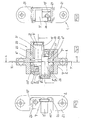
- the reference number 20 globally indicates a hinge for doors 3, or wings of furniture items, of the type hidden in the thickness of the door 3 and in the thickness of the related fixed door post 4, associated to the frame of the door itself or to the fixed structure of the furniture item.
- the hinge 20 (figure 1) essentially comprises fastening elements 1 and 2, stably secured to the door 3 and to the door post 4, and two arms 5', 5" which, advantageously articulated to each other and to the fastening elements 1, 2, allow to connect the door 3 pivotingly to the door post 4, as is necessary for the related opening and closing.
- Elastic return means 19 are positioned between the fastening elements 1, 2 and the two arms 5', 5".
- the fastening elements are embodied by corresponding internally hollow bodies 1 and 2, preferably made of metallic material and provided with planar flanges 21 ( Figures 4, 5 and 6).
- the bodies 1, 2 are housed in the thickness of the door 3 and of the door post 4 ( Figures 1, 2 and 3) and in the closed condition of the door 3 they are mutually opposite, but not aligned.
- Each of the bodies 1 and 2 is internally provided with a fixed pivot pin 7', 7" and with a groove, which embodies a sliding guide 9', 9".
- the pivot pins 7', 7" are oriented parallel to a vertical direction Z.
- the sliding guides 9', 9" are instead rectilinear and oriented orthogonal to the pivot pins 7', 7".
- Each arm 5', 5" is connected to both fastening elements 2, 1. More in particular, a first extremity 6', 6" of each ann 5', 5" is hinged on the fixed pivot pin 7', 7" of one of the fastening elements 2, 1, whilst the second extremity 8', 8", which is provided with a shoe 22, is engaged in the sliding guide 9", 9' of the other fastening element 2;1.
- the two arms 5', 5" are mutually connected in pivoting fashion by a joint 10 situated between the related extremities 6', 8', 6", 8".
- the arms 5', 5" generally have elongated, globally curvilinear shapes, differing in design and dimensions, devised to allow the door 3 to rotate relative to the door post 4 (Figure 2) between two extreme conditions: in the first whereof, the door 3 is closed and aligned with its own exterior face 13 to the outer finishing cornice 14 applied to the door post 4 ( Figure 1); in the second condition the door 3 being instead open and positioned with its own exterior face 13 in contrast with the outer cornice 14 of the post 4 and without substantial interposition of an intermediate empty space (Figure 3).
- first arm portions 11', 11 those parts of the arms 5', 5" that are situated between the first extremities 6', 6" and the intermediate joint 10 and as second arm portions 12', 12" those parts that are instead situated between the intermediate joint 10 and the second extremities 8', 8"
- first arm portions 11', 11 those parts of the arms 5', 5" that are situated between the first extremities 6', 6" and the intermediate joint 10
- second arm portions 12', 12 those parts that are instead situated between the intermediate joint 10 and the second extremities 8', 8
- the portions 11', 11", 12', 12" of said arms 5', 5" are embodied by a succession of segments positioned according to an advantageous broken line which, in the closed condition of the door 3, causes the first portions 11', 11" of the arms 5', 5" to be mutually angled according to a suitable angle alpha, whose amplitude is preferably close to 30°; and the second portions 12', 12" to be oriented, relative to the corresponding first portions, according to an angle beta substantially close to 105°.
- the hinge 20 is advantageously constructed in such a way as to be also adjustable according to the three spatial directions X, Y, Z and upon the activation of related adjustment means 16, 17, 18.
- the embodiment of the invention illustrated in the figures of the accompanying drawings provides in particular for the fastening elements 1, 2 to be constructed in such a way as to comprise: fixed parts embodied by the flanges 21 and movable parts embodied by distinct connecting bodies 15', 15" contained in their inner cavity.
- the connecting bodies 15', 15" which bear the pivot pins 7', 7" articulating the arms 5', 5", are able slidingly to translate relative to the fixed parts of the fastening elements 1, 2 along respective pairs of guide rods 26, 27 which are oriented along two mutually orthogonal horizontal directions.
- the adjustment means are in this case embodied in such a way as to comprise a second dowel 17 interposed between one of the connecting bodies 15', 15" and the related fastening element 1;2 and acting along a first horizontal direction X and an eccentric 18 positioned between the other connecting body 15", 15' and the related fastening element 1, 2 and acting according to a direction Y orthogonal to the first.
Claims (14)
- Une charnière dissimulée, en particulier pour portes ou pour volets des éléments de mobilier, comprenant des éléments de fixation (1, 2), pourvus de pivots fixes (7', 7'') et de guides coulissants (9', 9''), pouvant être logés respectivement dans l'épaisseur de la porte (3) et dans l'épaisseur d'un montant fixe (4) correspondant et étant mutuellement opposés lorsque la porte (3) est dans une position fermée; des bras (5', 5'') pour relier la porte (3) au montant (4), reliés aux éléments de fixation (1, 2) respectivement avec leur première extrémité (6', 6'') articulé sur le premier pivot (7', 7'') de l'un des éléments de fixation (1; 2), et avec une seconde extrémité (8', 8'') engagée dans le guide coulissant (9'', 9') de l'autre élément de fixation (2; 1); et une articulation (10) interposée aux extrémités (6', 8', 6'', 8'') des bras (5', 5'') qui relie en rotation les bras (5', 5'') entre eux en permettant leur mobilité angulaire relative, caractérisée en ce qu'au moins l'un des éléments de fixation (2; 1) comprend une partie fixe (21), fixée au respectif montant (4) de porte (3), et une partie mobile conformée en un corps de liaison (15''; 15') qui supporte l'un des pivots fixes (7'; 7'') articulant l'un des bras (5'; 5''), le corps de liaison (15''; 15') étant logé dans l'épaisseur du respectif montant (4) ou porte (3) intérieurement par rapport à la partie fixe (21), et pouvant translater de manière coulissante par rapport à la partie fixe (21) le long d'une première direction horizontale (X) perpendiculaire à un plan vertical intermédiaire entre les deux éléments de fixation (1, 2) lorsque la porte (3) est dans une position fermée, de manière à ce que les deux éléments de fixation (1, 2) soient mobiles l'un par rapport à l'autre le long de la première direction horizontale (X), la charnière dissimulée comprenant de plus des moyens de réglage (16, 17, 18) pour varier la position d'au moins le corps de liaison (15''; 15') au moins le long de la première direction horizontale (X).
- Une charnière, selon la revendication 1, caractérisée en ce que les éléments de fixation (1, 2) sont mobiles l'un par rapport à l'autre le long d'une direction verticale (Z) et en ce que les moyens de réglage (16, 17, 18) sont conçus pour effectuer un réglage de la position des éléments de fixation (1, 2) le long de la direction verticale (Z).
- Une charnière, selon la revendication 2, caractérisée en ce que lesdits moyens de réglage comprennent un premier goujon (16), pouvant pivoter, situé entre les bras (5', 5'') et orienté parallèlement à l'axe de rotation de l'articulation intermédiaire (10), ledit goujon (16) permettant de rapprocher ou, vice versa, d'éloigner les bras (5', 5'') en correspondance de directions opposées de sa rotation, au moins le long de la direction verticale (Z).
- Une charnière, selon n'importe laquelle des revendications précédentes, caractérisée en ce que même les autres éléments de fixation (1; 2) comprennent une respective partie fixe (21), fixée à la respective porte (3) ou au respectif montant (4), et une respective partie mobile conformée en un autre corps de liaison (15'; 15'') qui supporte l'autre des pivots fixes (7''; 7') articulant l'autre des bras (5''; 5'), ledit corps de liaison externe (15'; 15'') étant logé dans l'épaisseur de la respective porte (3) ou montant (4) intérieurement par rapport à la respective partie fixe (21) et pouvant translater de manière coulissante par rapport à la partie fixe (21) le long d'une autre direction horizontale (Y) perpendiculaire à la première direction horizontale (X), de manière à ce que les deux éléments de fixation (1, 2) soient mobiles l'un par rapport à l'autre le long de l'autre direction horizontale (Y), les moyens de réglage (16, 17, 18) étant conçus pour varier la position de l'autre corps de liaison (15'; 15'') le long de l'autre direction horizontale (Y).
- Une charnière, selon n'importe laquelle des revendications précédentes, caractérisée en ce que les moyens de réglage comprennent au moins un second goujon (17) interposé entre un corps de liaison (15', 15'') et le relatif élément de fixation (1; 2) et agissant le long d'une direction (X, Y) transversale à la direction verticale (Z).
- Une charnière, selon la revendication 5, caractérisée en ce que les moyens de réglage comprennent un excentrique (18) positionné entre un corps de liaison (15', 15'') et un relatif élément de fixation (1, 2) et agissant le long d'une direction (X; Y) transversale à la direction verticale (Z) pour régler en correspondance la charnière le long de ladite direction (X; Y).
- Une charnière, selon n'importe laquelle des revendications précédentes, caractérisée en ce que les bras (5', 5'') ont des longueurs mutuellement différentes au moins en correspondance de leur première portion (11', 11''), positionnée entre les respectives premières extrémités (6', 6'') et l'articulation intermédiaire (10), pour permettre l'ouverture de la porte (3) de par sa rotation par rapport au montant (4), jusqu'à une condition de parallélisme entre la porte (3) et le montant (4) et sans la substantielle interposition d'espace vide intermédiaire.
- Une charnière, selon la revendication 7, caractérisée en ce que lesdits bras (5', 5'') ont des longueurs mutuellement différentes en correspondance de leurs secondes portions (12', 12'') positionnées entre les secondes extrémités (8', 8'')et l'articulation (10).
- Une charnière, selon la revendication 7 ou 8, caractérisée en ce que les portions(11', 11'') ou (12', 12'') desdits bras (5', 5'') ont des formes allongées et comprennent une succession de segments disposés selon une ligne pointillée.
- Une charnière, selon n'importe laquelle des revendications précédentes 7 à 9, caractérisée en ce que les premières portions des bras (11', 11'') sont mutuellement angulairement séparées selon un angle alpha approprié.
- Une charnière, selon la revendication 10, caractérisée en ce que l'angle alpha a une amplitude substantiellement proche de 30°.
- Une charnière, selon n'importe laquelle des revendications précédentes 7 à 11, caractérisée en ce que les bras (5', 5'') sont dimensionnés et conformés pour permettre une rotation de la porte (3) par rapport au montant (4) entre deux conditions extrêmes, dans l'une desquelles la porte (3) est fermée et alignée avec sa propre face externe (13) à un cadre de finition (14) appliqué sur le montant (4), et dans l'autre la porte (3) étant au contraire ouverte et positionnée avec sa face externe (13) en contact avec le cadre (14) du montant (4).
- Une charnière, selon n'importe laquelle des revendications précédentes, caractérisée en ce qu'elle comprend des moyens élastiques de retour (19) positionnés entre les bras (5', 5'') et les éléments de fixation (1, 2).
- Une charnière, selon n'importe laquelle des revendications précédentes, caractérisée en ce que la porte (3), lorsqu'elle est dans la condition fermée, présente son propre plan perpendiculaire au plan vertical, intermédiaire entre les deux éléments de fixation (1, 2) lorsque la porte (3) est dans la position fermée, la variation de la position du corps de liaison (15'', 15') de l'un des éléments de fixation (2, 1) le long de la première direction horizontale (X) produisant un mouvement de la porte (3) dans son propre plan.
Priority Applications (2)
| Application Number | Priority Date | Filing Date | Title |
|---|---|---|---|
| DE20023445U DE20023445U1 (de) | 1999-06-25 | 2000-04-20 | Verstecktes Scharnier |
| DE60003494T DE60003494T3 (de) | 1999-06-25 | 2000-04-20 | Verstecktes Scharnier, insbesondere für Türen und/oder Flügel von Möbelelementen |
Applications Claiming Priority (2)
| Application Number | Priority Date | Filing Date | Title |
|---|---|---|---|
| ITRN990022U | 1999-06-25 | ||
| IT1999RN000022U IT248724Y1 (it) | 1999-06-25 | 1999-06-25 | Cerniera a scomparsa, in particolare per porte e/o per ante di mobili. |
Publications (4)
| Publication Number | Publication Date |
|---|---|
| EP1063376A2 EP1063376A2 (fr) | 2000-12-27 |
| EP1063376A3 EP1063376A3 (fr) | 2002-01-23 |
| EP1063376B1 true EP1063376B1 (fr) | 2003-06-25 |
| EP1063376B2 EP1063376B2 (fr) | 2012-11-21 |
Family
ID=11407259
Family Applications (1)
| Application Number | Title | Priority Date | Filing Date |
|---|---|---|---|
| EP00830304A Expired - Lifetime EP1063376B2 (fr) | 1999-06-25 | 2000-04-20 | Charnière dissimulée, en particulier pour portes et/ou volets des éléments de mobilier |
Country Status (8)
| Country | Link |
|---|---|
| US (1) | US6487755B1 (fr) |
| EP (1) | EP1063376B2 (fr) |
| CN (1) | CN1161530C (fr) |
| AT (1) | ATE243803T1 (fr) |
| CA (1) | CA2307242C (fr) |
| DE (2) | DE20023445U1 (fr) |
| ES (1) | ES2200805T5 (fr) |
| IT (1) | IT248724Y1 (fr) |
Cited By (4)
| Publication number | Priority date | Publication date | Assignee | Title |
|---|---|---|---|---|
| WO2007009174A1 (fr) * | 2005-07-18 | 2007-01-25 | Acin 1 Pty Ltd | Dispositif de couplage |
| DE102012101644B3 (de) * | 2012-02-29 | 2012-10-18 | Simonswerk, Gesellschaft mit beschränkter Haftung | Türband für eine verdeckte Anordnung zwischen Türzarge und Türflügel |
| USD745363S1 (en) | 2013-05-16 | 2015-12-15 | Sfs Intec Holding Ag | Hinge |
| RU2628969C2 (ru) * | 2013-05-16 | 2017-08-23 | Сфс Интек Холдинг Аг | Трехмерная регулируемая фурнитурная система |
Families Citing this family (42)
| Publication number | Priority date | Publication date | Assignee | Title |
|---|---|---|---|---|
| ES2335866T3 (es) | 2001-10-31 | 2010-04-06 | Simonswerk, Gesellschaft Mit Beschrankter Haftung | Bisagra de puerta para una disposicion oculta entre el cerco de la puerta y la hoja de la puerta. |
| DE10164979B4 (de) * | 2001-10-31 | 2007-08-09 | Simonswerk, Gmbh | Verdecktürband zur schwenkbaren Halterung eines Türflügels an einer Türzarge |
| DE10239446C1 (de) * | 2002-06-20 | 2003-08-14 | Simonswerk,Gmbh | Türband für eine verdeckte Anordnung zwischen Türzarge und Türflügel |
| US20050067927A1 (en) * | 2003-09-30 | 2005-03-31 | Wen-Te Ho | Collapsible closet |
| DE102004012350B3 (de) | 2004-03-11 | 2005-07-21 | Simonswerk, Gmbh | Türband für eine verdeckte Anordnung zwischen Türzarge und Türflügel |
| NZ537028A (en) * | 2004-12-06 | 2007-07-27 | Manfred Frank Systems Ltd | A hinge |
| US7565720B1 (en) * | 2005-04-01 | 2009-07-28 | Apple Inc. | Hinge mechanism with clutching function |
| EP1875023A1 (fr) * | 2005-04-13 | 2008-01-09 | Koninklijke Philips Electronics N.V. | Ensemble logement |
| US7192091B1 (en) | 2006-05-17 | 2007-03-20 | Agio International Company Limited | Folding sling chair |
| US20070283535A1 (en) * | 2006-06-01 | 2007-12-13 | The Hoffman Group, Llc | Vehicle gull-wing door hinge |
| US20070294860A1 (en) * | 2006-06-22 | 2007-12-27 | New Light, Llc | Vehicle door hinge |
| DE102007001283A1 (de) | 2007-01-08 | 2008-07-10 | Schreiber, Günter | Scharnier |
| DE102008027209B3 (de) * | 2008-06-06 | 2009-07-16 | Simonswerk, Gesellschaft mit beschränkter Haftung | Türband |
| DE102008057341B3 (de) * | 2008-11-14 | 2009-12-31 | Simonswerk, Gesellschaft mit beschränkter Haftung | Türband für eine verdeckte Anordnung zwischen Türzarge und Türflügel |
| BE1018621A5 (nl) * | 2008-12-23 | 2011-05-03 | Argent Alu Nv | Scharnier. |
| IT1394139B1 (it) * | 2009-04-09 | 2012-05-25 | Dierre Spa | Cerniera per porte, del tipo a scomparsa |
| US8627547B2 (en) * | 2009-05-08 | 2014-01-14 | Universal Industrial Products, Inc. | Invisible hinge with internal electrical wiring |
| DE102009043665A1 (de) * | 2009-09-29 | 2011-03-31 | SCHÜCO International KG | Schwenkbeschlag für Fenster oder Türen |
| DE102010011794B3 (de) * | 2009-11-13 | 2011-05-19 | Edgar Reinhard | Scharnier |
| IT1399280B1 (it) * | 2010-03-11 | 2013-04-11 | Florida Srl | Cerniera registrabile, a scomparsa, per serramenti |
| CN101832327A (zh) * | 2010-04-30 | 2010-09-15 | 李连英 | 一种铰链机构 |
| ITMI20101261A1 (it) * | 2010-07-08 | 2012-01-09 | Lualdi Spa | Cerniera |
| DE102011000150B3 (de) * | 2011-01-14 | 2011-10-06 | Simonswerk, Gesellschaft mit beschränkter Haftung | Türband für eine verdeckte Anordnung zwischen Türrahmen und Türflügel |
| DE102011050413B3 (de) * | 2011-05-17 | 2012-04-12 | Simonswerk, Gesellschaft mit beschränkter Haftung | Türband für eine verdeckte Anordnung zwischen Türflügel und Türzarge |
| BE1019987A5 (nl) * | 2011-05-23 | 2013-03-05 | Argent Alu Nv | Onzichtbaar scharnier. |
| GB2504281B (en) * | 2012-07-24 | 2014-10-15 | Blades Joinery Ltd | Door hinge |
| BE1020724A5 (nl) | 2012-09-04 | 2014-04-01 | Argent Alu Nv | Onzichtbaar scharnier. |
| CA2908308C (fr) * | 2013-04-12 | 2021-04-06 | In & Tec S.R.L. | Charniere pouvant etre cachee pour le mouvement de rotation regule d'une porte, en particulier d'une porte renforcee |
| CN103541616B (zh) * | 2013-10-28 | 2016-04-27 | 李刚 | 遥控自锁铰链 |
| CZ305075B6 (cs) * | 2013-12-05 | 2015-04-22 | Tokoz A.S. | Skrytý závěs |
| CN104799753B (zh) * | 2014-01-23 | 2017-10-31 | 厦门优胜卫厨科技有限公司 | 一种马桶盖板铰链翻盖机构 |
| CA2956536C (fr) | 2014-07-30 | 2022-03-01 | Manfred Frank Patent Holdings Limited | Charniere amelioree |
| CN104265103B (zh) * | 2014-09-18 | 2016-08-17 | 广东美的厨房电器制造有限公司 | 铰链和家用器具 |
| ITUB20152697A1 (it) * | 2015-07-31 | 2017-01-31 | Anselmi & C S R L | Cerniera registrabile a scomparsa. |
| AT517648B1 (de) * | 2015-09-04 | 2018-04-15 | Facc Ag | Scharnier |
| US10655383B2 (en) * | 2016-03-22 | 2020-05-19 | Olson Kundig, Inc. | System and method for implementing an improved bi-fold shutter |
| CN105735809A (zh) * | 2016-04-15 | 2016-07-06 | 刘文勋 | 铰链机构 |
| AT518903A1 (de) * | 2016-07-28 | 2018-02-15 | Tif Gmbh | Türscharnier für eine Duschtrennwand |
| DE102016125655B3 (de) | 2016-12-23 | 2018-06-21 | Solarlux Gmbh | Fixiervorrichtung für insbesondere Glasfaltanlagen |
| DE102017100270B3 (de) * | 2017-01-09 | 2018-01-11 | Simonswerk Gmbh | Türband sowie Zimmertür |
| DE102018100674B4 (de) | 2018-01-12 | 2020-03-05 | Hettich-Oni Gmbh & Co. Kg | Möbelplatte mit einem Scharnier und Möbel mit einer derartigen Möbelplatte |
| CN112343443A (zh) * | 2020-11-10 | 2021-02-09 | 福建西河卫浴科技有限公司 | 铰链装置和门体组件 |
Family Cites Families (16)
| Publication number | Priority date | Publication date | Assignee | Title |
|---|---|---|---|---|
| US1484093A (en) * | 1921-11-21 | 1924-02-19 | Soss Joseph | Hinge |
| US1688996A (en) * | 1926-03-01 | 1928-10-23 | Soss Joseph | Concealed hinge |
| US1925209A (en) * | 1932-06-18 | 1933-09-05 | Joseph Soss | Concealed hinge |
| US2021702A (en) * | 1934-11-28 | 1935-11-19 | Soss Joseph | Concealed hinge |
| US2178271A (en) * | 1937-08-05 | 1939-10-31 | Soss Joseph | Concealed hinge |
| FR1336667A (fr) * | 1961-01-12 | 1963-09-06 | Ohg Bassan & C S R L | Charnière |
| US3611474A (en) * | 1968-10-31 | 1971-10-12 | Stanley Works | Invisible hinge |
| DE2034614A1 (de) * | 1969-07-22 | 1971-02-11 | Cencioni, Livio, Apnlia, Latina (Italien) | An einer inneren Oberflache anzubringendes Scharnier |
| US3805323A (en) * | 1972-03-31 | 1974-04-23 | K Fukui | Invisible hinge and frame to be used for the same |
| AT353135B (de) * | 1973-12-12 | 1979-10-25 | Praemeta | Verdeckt anbringbares, seiten-und tiefenein- stellbares scharnier fuer tuerfluegel mit einem oeffnungswinkel bis zu 180 grad, insbesondere moebelscharnier |
| US3881221A (en) * | 1974-01-14 | 1975-05-06 | Sos Consolidated | Invisible hinge |
| DE3515907A1 (de) * | 1985-05-03 | 1986-11-06 | Häfele KG, 7270 Nagold | Scharnier, insbesondere moebelscharnier |
| US4827569A (en) * | 1986-08-01 | 1989-05-09 | Mertes Paul M | Flush mounted, fully concealed cabinet hinges |
| CH671066A5 (en) * | 1986-08-13 | 1989-07-31 | Brotschi & Co Ag Geb | Adjusting mechanism for door and window hinge |
| US4875252A (en) * | 1988-07-05 | 1989-10-24 | Universal Industrial Products., A Division Of Core Industries, Inc. | Self-closing invisible hinge with selectively variable closing force |
| US4843680A (en) * | 1988-10-28 | 1989-07-04 | Amerock Corporation | Hinge particularly adapted for use with a false cabinet front |
-
1999
- 1999-06-25 IT IT1999RN000022U patent/IT248724Y1/it active
-
2000
- 2000-04-20 DE DE20023445U patent/DE20023445U1/de not_active Expired - Lifetime
- 2000-04-20 EP EP00830304A patent/EP1063376B2/fr not_active Expired - Lifetime
- 2000-04-20 ES ES00830304T patent/ES2200805T5/es not_active Expired - Lifetime
- 2000-04-20 DE DE60003494T patent/DE60003494T3/de not_active Expired - Lifetime
- 2000-04-20 AT AT00830304T patent/ATE243803T1/de active
- 2000-04-27 CA CA002307242A patent/CA2307242C/fr not_active Expired - Lifetime
- 2000-04-28 US US09/560,588 patent/US6487755B1/en not_active Expired - Lifetime
- 2000-04-30 CN CNB001082175A patent/CN1161530C/zh not_active Ceased
Cited By (8)
| Publication number | Priority date | Publication date | Assignee | Title |
|---|---|---|---|---|
| WO2007009174A1 (fr) * | 2005-07-18 | 2007-01-25 | Acin 1 Pty Ltd | Dispositif de couplage |
| DE102012101644B3 (de) * | 2012-02-29 | 2012-10-18 | Simonswerk, Gesellschaft mit beschränkter Haftung | Türband für eine verdeckte Anordnung zwischen Türzarge und Türflügel |
| EP2634335A2 (fr) | 2012-02-29 | 2013-09-04 | Simonswerk, Gesellschaft mit beschränkter Haftung | Penture de porte pour un agencement couvert entre une huisserie et un vantail |
| DE202013012258U1 (de) | 2012-02-29 | 2015-11-16 | Simonswerk, Gesellschaft mit beschränkter Haftung | Türband für eine verdeckte Anordnung zwischen Türzarge und Türflügel |
| RU2597554C2 (ru) * | 2012-02-29 | 2016-09-10 | Симонсверк, Гезелльшафт Мит Бешрэнктер Хафтунг | Дверная петля скрытого расположения между дверной коробкой и дверным полотном |
| EP2634335A3 (fr) * | 2012-02-29 | 2016-10-19 | Simonswerk, Gesellschaft mit beschränkter Haftung | Penture de porte pour un agencement couvert entre une huisserie et un vantail |
| USD745363S1 (en) | 2013-05-16 | 2015-12-15 | Sfs Intec Holding Ag | Hinge |
| RU2628969C2 (ru) * | 2013-05-16 | 2017-08-23 | Сфс Интек Холдинг Аг | Трехмерная регулируемая фурнитурная система |
Also Published As
| Publication number | Publication date |
|---|---|
| DE20023445U1 (de) | 2004-05-13 |
| CN1161530C (zh) | 2004-08-11 |
| ITRN990022U1 (it) | 2000-12-25 |
| ES2200805T5 (es) | 2013-03-07 |
| EP1063376A3 (fr) | 2002-01-23 |
| CA2307242A1 (fr) | 2000-12-25 |
| DE60003494D1 (de) | 2003-07-31 |
| DE60003494T2 (de) | 2004-05-19 |
| ES2200805T3 (es) | 2004-03-16 |
| CA2307242C (fr) | 2008-09-02 |
| US6487755B1 (en) | 2002-12-03 |
| DE60003494T3 (de) | 2013-03-21 |
| EP1063376A2 (fr) | 2000-12-27 |
| CN1279332A (zh) | 2001-01-10 |
| EP1063376B2 (fr) | 2012-11-21 |
| IT248724Y1 (it) | 2003-02-12 |
| ATE243803T1 (de) | 2003-07-15 |
Similar Documents
| Publication | Publication Date | Title |
|---|---|---|
| EP1063376B1 (fr) | Charnière dissimulée, en particulier pour portes et/ou volets des éléments de mobilier | |
| US20030088943A1 (en) | Door hinge for a covered arrangement between door post and door | |
| CN102587760A (zh) | 用于隐蔽地布置在门框和门扇之间的门铰链 | |
| EP1612355A2 (fr) | Dispositif de charnière cachée pour une fenêtre ou porte oscillo-battante | |
| CN113585900B (zh) | 一种能顺序大角度开合的暗铰链 | |
| CN108868409B (zh) | 具有防夹功能的铰链和用于调节铰链的固定件的方法 | |
| CA2176075A1 (fr) | Dispositif mobile ameliore pour ouvrir et fermer la porte d'une garde-robe | |
| US5033160A (en) | Hinge, preferably for hinging a door or flap to a carrying wall of a furniture corpus | |
| CN211448232U (zh) | 一种窗用重型滑撑 | |
| JPH0730649B2 (ja) | ドア、或いは、フラップを家具本体の支持壁にヒンジ止めするためのヒンジ | |
| US11149483B2 (en) | Furniture hinge, furniture panel, and furniture body | |
| US4297763A (en) | Furniture hinge | |
| RU2522100C2 (ru) | Фурнитура | |
| US5465463A (en) | Corner cabinet hinge | |
| GB2228766A (en) | Friction stay-hinge | |
| JP5346579B2 (ja) | ヒンジ | |
| EP3971377B1 (fr) | Charnière, ensemble châssis-vitrage pour fermer une ouverture et processus de réglage d'un ensemble châssis-vitrage | |
| WO2006042438A3 (fr) | Ferrure pour fenetre battante | |
| CN116348654A (zh) | 具有多铰接机构的家具配件 | |
| CA2511955A1 (fr) | Unite d'armature pour fenetre ou porte | |
| CN115349045A (zh) | 容器柜 | |
| CN112211515A (zh) | 一种门缝微缝三维可调重型暗铰链 | |
| IT9020210A1 (it) | Dispositivo di cerniera per trasferire un'anta di un mobile da una posizione di apertura ad una posizione di chiusura | |
| CS219463B1 (cs) | Otočný závěs | |
| ITBO940112U1 (it) | Porta pieghevole con movimenti ammortizzati |
Legal Events
| Date | Code | Title | Description |
|---|---|---|---|
| PUAI | Public reference made under article 153(3) epc to a published international application that has entered the european phase |
Free format text: ORIGINAL CODE: 0009012 |
|
| AK | Designated contracting states |
Kind code of ref document: A2 Designated state(s): AT BE CH CY DE DK ES FI FR GB GR IE IT LI LU MC NL PT SE |
|
| AX | Request for extension of the european patent |
Free format text: AL;LT;LV;MK;RO;SI |
|
| PUAL | Search report despatched |
Free format text: ORIGINAL CODE: 0009013 |
|
| AK | Designated contracting states |
Kind code of ref document: A3 Designated state(s): AT BE CH CY DE DK ES FI FR GB GR IE IT LI LU MC NL PT SE |
|
| AX | Request for extension of the european patent |
Free format text: AL;LT;LV;MK;RO;SI |
|
| RIC1 | Information provided on ipc code assigned before grant |
Free format text: 7E 05D 3/06 A, 7E 05D 7/00 B, 7E 05D 7/04 B |
|
| 17P | Request for examination filed |
Effective date: 20020315 |
|
| 17Q | First examination report despatched |
Effective date: 20020715 |
|
| AKX | Designation fees paid |
Free format text: AT BE CH CY DE DK ES FI FR GB GR IE IT LI LU MC NL PT SE |
|
| GRAH | Despatch of communication of intention to grant a patent |
Free format text: ORIGINAL CODE: EPIDOS IGRA |
|
| GRAH | Despatch of communication of intention to grant a patent |
Free format text: ORIGINAL CODE: EPIDOS IGRA |
|
| GRAA | (expected) grant |
Free format text: ORIGINAL CODE: 0009210 |
|
| AK | Designated contracting states |
Designated state(s): AT BE CH CY DE DK ES FI FR GB GR IE IT LI LU MC NL PT SE |
|
| PG25 | Lapsed in a contracting state [announced via postgrant information from national office to epo] |
Ref country code: FI Free format text: LAPSE BECAUSE OF FAILURE TO SUBMIT A TRANSLATION OF THE DESCRIPTION OR TO PAY THE FEE WITHIN THE PRESCRIBED TIME-LIMIT Effective date: 20030625 Ref country code: CY Free format text: LAPSE BECAUSE OF FAILURE TO SUBMIT A TRANSLATION OF THE DESCRIPTION OR TO PAY THE FEE WITHIN THE PRESCRIBED TIME-LIMIT Effective date: 20030625 |
|
| REG | Reference to a national code |
Ref country code: GB Ref legal event code: FG4D |
|
| REG | Reference to a national code |
Ref country code: CH Ref legal event code: EP |
|
| REG | Reference to a national code |
Ref country code: IE Ref legal event code: FG4D |
|
| REF | Corresponds to: |
Ref document number: 60003494 Country of ref document: DE Date of ref document: 20030731 Kind code of ref document: P |
|
| REG | Reference to a national code |
Ref country code: CH Ref legal event code: NV Representative=s name: BUGNION S.A. |
|
| REG | Reference to a national code |
Ref country code: SE Ref legal event code: TRGR |
|
| PG25 | Lapsed in a contracting state [announced via postgrant information from national office to epo] |
Ref country code: PT Free format text: LAPSE BECAUSE OF FAILURE TO SUBMIT A TRANSLATION OF THE DESCRIPTION OR TO PAY THE FEE WITHIN THE PRESCRIBED TIME-LIMIT Effective date: 20030925 Ref country code: GR Free format text: LAPSE BECAUSE OF FAILURE TO SUBMIT A TRANSLATION OF THE DESCRIPTION OR TO PAY THE FEE WITHIN THE PRESCRIBED TIME-LIMIT Effective date: 20030925 Ref country code: DK Free format text: LAPSE BECAUSE OF FAILURE TO SUBMIT A TRANSLATION OF THE DESCRIPTION OR TO PAY THE FEE WITHIN THE PRESCRIBED TIME-LIMIT Effective date: 20030925 |
|
| REG | Reference to a national code |
Ref country code: ES Ref legal event code: FG2A Ref document number: 2200805 Country of ref document: ES Kind code of ref document: T3 |
|
| PLBQ | Unpublished change to opponent data |
Free format text: ORIGINAL CODE: EPIDOS OPPO |
|
| PLBI | Opposition filed |
Free format text: ORIGINAL CODE: 0009260 |
|
| PLBQ | Unpublished change to opponent data |
Free format text: ORIGINAL CODE: EPIDOS OPPO |
|
| ET | Fr: translation filed | ||
| PG25 | Lapsed in a contracting state [announced via postgrant information from national office to epo] |
Ref country code: IE Free format text: LAPSE BECAUSE OF NON-PAYMENT OF DUE FEES Effective date: 20040420 Ref country code: LU Free format text: LAPSE BECAUSE OF NON-PAYMENT OF DUE FEES Effective date: 20040420 |
|
| PLAX | Notice of opposition and request to file observation + time limit sent |
Free format text: ORIGINAL CODE: EPIDOSNOBS2 |
|
| PG25 | Lapsed in a contracting state [announced via postgrant information from national office to epo] |
Ref country code: MC Free format text: LAPSE BECAUSE OF NON-PAYMENT OF DUE FEES Effective date: 20040430 |
|
| 26 | Opposition filed |
Opponent name: CEAM AMADEO S.P.A. Effective date: 20040322 Opponent name: SIMONSWERK GMBH Effective date: 20040323 |
|
| NLR1 | Nl: opposition has been filed with the epo |
Opponent name: CEAM AMADEO S.P.A. Opponent name: SIMONSWERK GMBH |
|
| PLBB | Reply of patent proprietor to notice(s) of opposition received |
Free format text: ORIGINAL CODE: EPIDOSNOBS3 |
|
| REG | Reference to a national code |
Ref country code: IE Ref legal event code: MM4A |
|
| APBP | Date of receipt of notice of appeal recorded |
Free format text: ORIGINAL CODE: EPIDOSNNOA2O |
|
| APAH | Appeal reference modified |
Free format text: ORIGINAL CODE: EPIDOSCREFNO |
|
| APBP | Date of receipt of notice of appeal recorded |
Free format text: ORIGINAL CODE: EPIDOSNNOA2O |
|
| APBP | Date of receipt of notice of appeal recorded |
Free format text: ORIGINAL CODE: EPIDOSNNOA2O |
|
| APBQ | Date of receipt of statement of grounds of appeal recorded |
Free format text: ORIGINAL CODE: EPIDOSNNOA3O |
|
| APBQ | Date of receipt of statement of grounds of appeal recorded |
Free format text: ORIGINAL CODE: EPIDOSNNOA3O |
|
| APBQ | Date of receipt of statement of grounds of appeal recorded |
Free format text: ORIGINAL CODE: EPIDOSNNOA3O |
|
| PLBP | Opposition withdrawn |
Free format text: ORIGINAL CODE: 0009264 |
|
| APAH | Appeal reference modified |
Free format text: ORIGINAL CODE: EPIDOSCREFNO |
|
| APBU | Appeal procedure closed |
Free format text: ORIGINAL CODE: EPIDOSNNOA9O |
|
| PLAY | Examination report in opposition despatched + time limit |
Free format text: ORIGINAL CODE: EPIDOSNORE2 |
|
| PLBC | Reply to examination report in opposition received |
Free format text: ORIGINAL CODE: EPIDOSNORE3 |
|
| PLAZ | Examination of admissibility of opposition: despatch of communication + time limit |
Free format text: ORIGINAL CODE: EPIDOSNOPE2 |
|
| PLBA | Examination of admissibility of opposition: reply received |
Free format text: ORIGINAL CODE: EPIDOSNOPE4 |
|
| PLAB | Opposition data, opponent's data or that of the opponent's representative modified |
Free format text: ORIGINAL CODE: 0009299OPPO |
|
| PUAH | Patent maintained in amended form |
Free format text: ORIGINAL CODE: 0009272 |
|
| STAA | Information on the status of an ep patent application or granted ep patent |
Free format text: STATUS: PATENT MAINTAINED AS AMENDED |
|
| 27A | Patent maintained in amended form |
Effective date: 20121121 |
|
| AK | Designated contracting states |
Kind code of ref document: B2 Designated state(s): AT BE CH CY DE DK ES FI FR GB GR IE IT LI LU MC NL PT SE |
|
| REG | Reference to a national code |
Ref country code: CH Ref legal event code: AELC |
|
| REG | Reference to a national code |
Ref country code: DE Ref legal event code: R102 Ref document number: 60003494 Country of ref document: DE Effective date: 20121121 |
|
| REG | Reference to a national code |
Ref country code: SE Ref legal event code: RPEO |
|
| REG | Reference to a national code |
Ref country code: ES Ref legal event code: DC2A Ref document number: 2200805 Country of ref document: ES Kind code of ref document: T5 Effective date: 20130307 |
|
| REG | Reference to a national code |
Ref country code: NL Ref legal event code: T3 |
|
| REG | Reference to a national code |
Ref country code: FR Ref legal event code: PLFP Year of fee payment: 17 |
|
| REG | Reference to a national code |
Ref country code: FR Ref legal event code: PLFP Year of fee payment: 18 |
|
| REG | Reference to a national code |
Ref country code: FR Ref legal event code: PLFP Year of fee payment: 19 |
|
| PGFP | Annual fee paid to national office [announced via postgrant information from national office to epo] |
Ref country code: NL Payment date: 20190430 Year of fee payment: 20 |
|
| PGFP | Annual fee paid to national office [announced via postgrant information from national office to epo] |
Ref country code: IT Payment date: 20190424 Year of fee payment: 20 Ref country code: ES Payment date: 20190520 Year of fee payment: 20 Ref country code: DE Payment date: 20190503 Year of fee payment: 20 |
|
| PGFP | Annual fee paid to national office [announced via postgrant information from national office to epo] |
Ref country code: SE Payment date: 20190430 Year of fee payment: 20 Ref country code: FR Payment date: 20190430 Year of fee payment: 20 Ref country code: BE Payment date: 20190429 Year of fee payment: 20 |
|
| PGFP | Annual fee paid to national office [announced via postgrant information from national office to epo] |
Ref country code: CH Payment date: 20190430 Year of fee payment: 20 |
|
| PGFP | Annual fee paid to national office [announced via postgrant information from national office to epo] |
Ref country code: AT Payment date: 20190429 Year of fee payment: 20 Ref country code: GB Payment date: 20190430 Year of fee payment: 20 |
|
| REG | Reference to a national code |
Ref country code: DE Ref legal event code: R071 Ref document number: 60003494 Country of ref document: DE |
|
| REG | Reference to a national code |
Ref country code: NL Ref legal event code: MK Effective date: 20200419 |
|
| REG | Reference to a national code |
Ref country code: CH Ref legal event code: PL |
|
| REG | Reference to a national code |
Ref country code: GB Ref legal event code: PE20 Expiry date: 20200419 |
|
| REG | Reference to a national code |
Ref country code: BE Ref legal event code: MK Effective date: 20200420 |
|
| REG | Reference to a national code |
Ref country code: ES Ref legal event code: FD2A Effective date: 20200803 |
|
| REG | Reference to a national code |
Ref country code: AT Ref legal event code: MK07 Ref document number: 243803 Country of ref document: AT Kind code of ref document: T Effective date: 20200420 |
|
| PG25 | Lapsed in a contracting state [announced via postgrant information from national office to epo] |
Ref country code: GB Free format text: LAPSE BECAUSE OF EXPIRATION OF PROTECTION Effective date: 20200419 |
|
| PG25 | Lapsed in a contracting state [announced via postgrant information from national office to epo] |
Ref country code: ES Free format text: LAPSE BECAUSE OF EXPIRATION OF PROTECTION Effective date: 20200421 |