EP1063376B1 - Hidden hinge, in particular for doors and/or wings of furniture items - Google Patents
Hidden hinge, in particular for doors and/or wings of furniture items Download PDFInfo
- Publication number
- EP1063376B1 EP1063376B1 EP00830304A EP00830304A EP1063376B1 EP 1063376 B1 EP1063376 B1 EP 1063376B1 EP 00830304 A EP00830304 A EP 00830304A EP 00830304 A EP00830304 A EP 00830304A EP 1063376 B1 EP1063376 B1 EP 1063376B1
- Authority
- EP
- European Patent Office
- Prior art keywords
- door
- arms
- fastening elements
- hinge
- along
- Prior art date
- Legal status (The legal status is an assumption and is not a legal conclusion. Google has not performed a legal analysis and makes no representation as to the accuracy of the status listed.)
- Expired - Lifetime
Links
Images


Classifications
-
- E—FIXED CONSTRUCTIONS
- E05—LOCKS; KEYS; WINDOW OR DOOR FITTINGS; SAFES
- E05D—HINGES OR SUSPENSION DEVICES FOR DOORS, WINDOWS OR WINGS
- E05D3/00—Hinges with pins
- E05D3/06—Hinges with pins with two or more pins
- E05D3/18—Hinges with pins with two or more pins with sliding pins or guides
- E05D3/186—Scissors hinges, with two crossing levers and five parallel pins
-
- E—FIXED CONSTRUCTIONS
- E05—LOCKS; KEYS; WINDOW OR DOOR FITTINGS; SAFES
- E05D—HINGES OR SUSPENSION DEVICES FOR DOORS, WINDOWS OR WINGS
- E05D3/00—Hinges with pins
- E05D3/06—Hinges with pins with two or more pins
- E05D3/18—Hinges with pins with two or more pins with sliding pins or guides
- E05D3/183—Hinges with pins with two or more pins with sliding pins or guides with at least one of the hinge parts having a cup-shaped fixing part, e.g. for attachment to cabinets or furniture
-
- E—FIXED CONSTRUCTIONS
- E05—LOCKS; KEYS; WINDOW OR DOOR FITTINGS; SAFES
- E05D—HINGES OR SUSPENSION DEVICES FOR DOORS, WINDOWS OR WINGS
- E05D7/00—Hinges or pivots of special construction
- E05D7/0009—Adjustable hinges
- E05D7/0018—Adjustable hinges at the hinge axis
- E05D7/0027—Adjustable hinges at the hinge axis in an axial direction
-
- E—FIXED CONSTRUCTIONS
- E05—LOCKS; KEYS; WINDOW OR DOOR FITTINGS; SAFES
- E05D—HINGES OR SUSPENSION DEVICES FOR DOORS, WINDOWS OR WINGS
- E05D7/00—Hinges or pivots of special construction
- E05D7/04—Hinges adjustable relative to the wing or the frame
- E05D7/0415—Hinges adjustable relative to the wing or the frame with adjusting drive means
- E05D7/0423—Screw-and-nut mechanisms
-
- E—FIXED CONSTRUCTIONS
- E05—LOCKS; KEYS; WINDOW OR DOOR FITTINGS; SAFES
- E05D—HINGES OR SUSPENSION DEVICES FOR DOORS, WINDOWS OR WINGS
- E05D7/00—Hinges or pivots of special construction
- E05D7/04—Hinges adjustable relative to the wing or the frame
- E05D2007/0469—Hinges adjustable relative to the wing or the frame in an axial direction
-
- E—FIXED CONSTRUCTIONS
- E05—LOCKS; KEYS; WINDOW OR DOOR FITTINGS; SAFES
- E05D—HINGES OR SUSPENSION DEVICES FOR DOORS, WINDOWS OR WINGS
- E05D7/00—Hinges or pivots of special construction
- E05D7/04—Hinges adjustable relative to the wing or the frame
- E05D2007/0484—Hinges adjustable relative to the wing or the frame in a radial direction
-
- E—FIXED CONSTRUCTIONS
- E05—LOCKS; KEYS; WINDOW OR DOOR FITTINGS; SAFES
- E05Y—INDEXING SCHEME RELATING TO HINGES OR OTHER SUSPENSION DEVICES FOR DOORS, WINDOWS OR WINGS AND DEVICES FOR MOVING WINGS INTO OPEN OR CLOSED POSITION, CHECKS FOR WINGS AND WING FITTINGS NOT OTHERWISE PROVIDED FOR, CONCERNED WITH THE FUNCTIONING OF THE WING
- E05Y2900/00—Application of doors, windows, wings or fittings thereof
- E05Y2900/20—Application of doors, windows, wings or fittings thereof for furnitures, e.g. cabinets
Definitions
- the present invention relates to the manufacture of wings of furniture items and doors in general and in particular it pertains to hidden hinges to articulate the wings to the fixed part of the furniture item and more in general the doors to the related door post.
- hinges are partly contained inside the thickness of the door and partly inside the thickness of the door post and comprise in particular two fastening elements to connect the hinge respectively to the door and to the door post; arms, each of which is connected to the two fastening elements with their first extremity hinged on a fixed pivot pin of one of the fastening elements and with the other extremity engaged in a sliding guide borne by the other fastening element; and lastly a pivot pin, interposed at the extremities of the arms, which connects the arms in mutually pivoting fashion being able to move, remaining parallel to itself, in the opening and closing motion of the door.
- a hidden hinge of this kind comprising all the characteristics of the preamble of Claim 1, is for example known from document US 32 09 390 A.
- a hinge between a door and a post is shown, which allows rotation along a single bolt.
- the hinge is not hidden, its fastening elements being located outside the door and the post.
- the fastening elements are movable relative to each other along a vertical direction which coincides with the axis of the bolt.
- the relative position of the fastening elements may be adjusted also along two horizontal directions.
- the arms are equal in shape and dimensions and are generally perfectly reversible relative to each other.
- the fastening elements contained in the thickness of the wing and of the door post are opposite and mutually aligned.
- This conformation of the hinges generally determines the impossibility of positioning the door, in the open condition, flush with the door post when this post is provided with an outer finishing cornice.
- the distance, measured between the front surface of the post and the plane of the door opened at an angle of 180 degrees, is never sufficient to permit the application of a standard finishing cornice, the thickness of which is always greater than such a distance.
- the door would open only partially, at an angle of approximately 90 to 100 degrees, unless hollows are produced in the front part of the post so as to allow the application of the cornice, but thus greatly increasing the number of operations and the time needed for the application itself.
- the aim of the present invention is to eliminate such drawbacks by means of a hinge so shaped as to allow the wing to position itself, in the open condition, rigorously flush with a door post having a finishing cornice, the hinge being adjustable along the three cartesian axes, thus permitting the adjustment of door verticality and squaring and the recovery of any imperfection in the assembly.
- this aim is reached by a hinge according to claim 1, wherein the arms have mutually different lengths, at least in correspondence with their portion positioned between the respective first extremities and the intermediate articulation pivot pin, to allow the complete rotation of the door relative to the door post up to an angle of 180 degrees, at least until reaching a condition in which the door is positioned parallel to the finishing cornice.
- the hinge is also provided with adjustment means which allow in particular to adjust the arms along a vertical direction passing through the intermediate pivot pin.
- the hinge according to the invention is also adjustable in all directions in space.
- the reference number 20 globally indicates a hinge for doors 3, or wings of furniture items, of the type hidden in the thickness of the door 3 and in the thickness of the related fixed door post 4, associated to the frame of the door itself or to the fixed structure of the furniture item.
- the hinge 20 (figure 1) essentially comprises fastening elements 1 and 2, stably secured to the door 3 and to the door post 4, and two arms 5', 5" which, advantageously articulated to each other and to the fastening elements 1, 2, allow to connect the door 3 pivotingly to the door post 4, as is necessary for the related opening and closing.
- Elastic return means 19 are positioned between the fastening elements 1, 2 and the two arms 5', 5".
- the fastening elements are embodied by corresponding internally hollow bodies 1 and 2, preferably made of metallic material and provided with planar flanges 21 ( Figures 4, 5 and 6).
- the bodies 1, 2 are housed in the thickness of the door 3 and of the door post 4 ( Figures 1, 2 and 3) and in the closed condition of the door 3 they are mutually opposite, but not aligned.
- Each of the bodies 1 and 2 is internally provided with a fixed pivot pin 7', 7" and with a groove, which embodies a sliding guide 9', 9".
- the pivot pins 7', 7" are oriented parallel to a vertical direction Z.
- the sliding guides 9', 9" are instead rectilinear and oriented orthogonal to the pivot pins 7', 7".
- Each arm 5', 5" is connected to both fastening elements 2, 1. More in particular, a first extremity 6', 6" of each ann 5', 5" is hinged on the fixed pivot pin 7', 7" of one of the fastening elements 2, 1, whilst the second extremity 8', 8", which is provided with a shoe 22, is engaged in the sliding guide 9", 9' of the other fastening element 2;1.
- the two arms 5', 5" are mutually connected in pivoting fashion by a joint 10 situated between the related extremities 6', 8', 6", 8".
- the arms 5', 5" generally have elongated, globally curvilinear shapes, differing in design and dimensions, devised to allow the door 3 to rotate relative to the door post 4 (Figure 2) between two extreme conditions: in the first whereof, the door 3 is closed and aligned with its own exterior face 13 to the outer finishing cornice 14 applied to the door post 4 ( Figure 1); in the second condition the door 3 being instead open and positioned with its own exterior face 13 in contrast with the outer cornice 14 of the post 4 and without substantial interposition of an intermediate empty space (Figure 3).
- first arm portions 11', 11 those parts of the arms 5', 5" that are situated between the first extremities 6', 6" and the intermediate joint 10 and as second arm portions 12', 12" those parts that are instead situated between the intermediate joint 10 and the second extremities 8', 8"
- first arm portions 11', 11 those parts of the arms 5', 5" that are situated between the first extremities 6', 6" and the intermediate joint 10
- second arm portions 12', 12 those parts that are instead situated between the intermediate joint 10 and the second extremities 8', 8
- the portions 11', 11", 12', 12" of said arms 5', 5" are embodied by a succession of segments positioned according to an advantageous broken line which, in the closed condition of the door 3, causes the first portions 11', 11" of the arms 5', 5" to be mutually angled according to a suitable angle alpha, whose amplitude is preferably close to 30°; and the second portions 12', 12" to be oriented, relative to the corresponding first portions, according to an angle beta substantially close to 105°.
- the hinge 20 is advantageously constructed in such a way as to be also adjustable according to the three spatial directions X, Y, Z and upon the activation of related adjustment means 16, 17, 18.
- the embodiment of the invention illustrated in the figures of the accompanying drawings provides in particular for the fastening elements 1, 2 to be constructed in such a way as to comprise: fixed parts embodied by the flanges 21 and movable parts embodied by distinct connecting bodies 15', 15" contained in their inner cavity.
- the connecting bodies 15', 15" which bear the pivot pins 7', 7" articulating the arms 5', 5", are able slidingly to translate relative to the fixed parts of the fastening elements 1, 2 along respective pairs of guide rods 26, 27 which are oriented along two mutually orthogonal horizontal directions.
- the adjustment means are in this case embodied in such a way as to comprise a second dowel 17 interposed between one of the connecting bodies 15', 15" and the related fastening element 1;2 and acting along a first horizontal direction X and an eccentric 18 positioned between the other connecting body 15", 15' and the related fastening element 1, 2 and acting according to a direction Y orthogonal to the first.
Abstract
Description
- The present invention relates to the manufacture of wings of furniture items and doors in general and in particular it pertains to hidden hinges to articulate the wings to the fixed part of the furniture item and more in general the doors to the related door post.
- These hinges, currently called invisible hinges, are partly contained inside the thickness of the door and partly inside the thickness of the door post and comprise in particular two fastening elements to connect the hinge respectively to the door and to the door post; arms, each of which is connected to the two fastening elements with their first extremity hinged on a fixed pivot pin of one of the fastening elements and with the other extremity engaged in a sliding guide borne by the other fastening element; and lastly a pivot pin, interposed at the extremities of the arms, which connects the arms in mutually pivoting fashion being able to move, remaining parallel to itself, in the opening and closing motion of the door.
- A hidden hinge of this kind, comprising all the characteristics of the preamble of
Claim 1, is for example known from document US 32 09 390 A. - In rather complicated and sophisticated hinges of this kind no adjustment in any of three directions in space is permitted to the door with respect to its fixed posh Infact, they are provided with fastening means of the hinge which are articulated exclusively with one another, but fixed in space once applied.
- In document CH 671 066 A a hinge between a door and a post is shown, which allows rotation along a single bolt. The hinge is not hidden, its fastening elements being located outside the door and the post. The fastening elements are movable relative to each other along a vertical direction which coincides with the axis of the bolt. The relative position of the fastening elements may be adjusted also along two horizontal directions.
- Furthermore, in known hinges of this kind, the arms are equal in shape and dimensions and are generally perfectly reversible relative to each other. Moreover, the fastening elements contained in the thickness of the wing and of the door post are opposite and mutually aligned.
- This conformation of the hinges generally determines the impossibility of positioning the door, in the open condition, flush with the door post when this post is provided with an outer finishing cornice.
- In practice, the distance, measured between the front surface of the post and the plane of the door opened at an angle of 180 degrees, is never sufficient to permit the application of a standard finishing cornice, the thickness of which is always greater than such a distance. Generally, therefore, if, as almost always happens, the cited finishing cornices were to be applied on the exterior of the post, the door would open only partially, at an angle of approximately 90 to 100 degrees, unless hollows are produced in the front part of the post so as to allow the application of the cornice, but thus greatly increasing the number of operations and the time needed for the application itself.
- The aim of the present invention is to eliminate such drawbacks by means of a hinge so shaped as to allow the wing to position itself, in the open condition, rigorously flush with a door post having a finishing cornice, the hinge being adjustable along the three cartesian axes, thus permitting the adjustment of door verticality and squaring and the recovery of any imperfection in the assembly.
- In accordance with the invention this aim is reached by a hinge according to
claim 1, wherein the arms have mutually different lengths, at least in correspondence with their portion positioned between the respective first extremities and the intermediate articulation pivot pin, to allow the complete rotation of the door relative to the door post up to an angle of 180 degrees, at least until reaching a condition in which the door is positioned parallel to the finishing cornice. - The hinge is also provided with adjustment means which allow in particular to adjust the arms along a vertical direction passing through the intermediate pivot pin.
- If the adjustment means are so devised as to allow also the adjustment of the hinge along two additional horizontal directions orthogonal to each other and to the vertical direction, the hinge according to the invention is also adjustable in all directions in space.
- The technical features of the invention, according to the aforesaid aims, can clearly be noted from the content of the claims set out below and its advantages shall become more readily apparent in the detailed description that follows, made with reference to the accompanying drawings, which show an embodiment provided purely by way of non limiting example, in which:
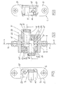
- Figure 1 is a top plan view of a door and of a door post shown in closed condition, provided with hinges according to the invention, and sectioned at the height of one of the hinges with section plane indicated with trace I-I in Figure 4;
- Figures 2 and 3 are top plan views of the door and of the door post sectioned as in Figure 1 and shown respectively in a partially opened and in a fully opened condition of the door;
- Figure 4 is an overall view of the hinge sectioned with a vertical plane of trace IV-IV indicated in Figure 1, showing a view of the arms of the hinges not sectioned;
- Figures 5 and 6 are views of the hinge of Figure 4 sectioned respectively with the planes V-V and VI-VI and shown with some parts removed the better to highlight others;
- Figure 7 is a view corresponding to Figure 4 showing the hinge in a sample adjustment condition.
- With reference to the accompanying drawings, the
reference number 20 globally indicates a hinge fordoors 3, or wings of furniture items, of the type hidden in the thickness of thedoor 3 and in the thickness of the related fixeddoor post 4, associated to the frame of the door itself or to the fixed structure of the furniture item. - The hinge 20 (figure 1) essentially comprises
fastening elements door 3 and to thedoor post 4, and twoarms 5', 5" which, advantageously articulated to each other and to thefastening elements door 3 pivotingly to thedoor post 4, as is necessary for the related opening and closing. Elastic return means 19 are positioned between thefastening elements arms 5', 5". - In particular, the fastening elements are embodied by corresponding internally
hollow bodies bodies door 3 and of the door post 4 (Figures 1, 2 and 3) and in the closed condition of thedoor 3 they are mutually opposite, but not aligned. - Each of the
bodies pivot pin 7', 7" and with a groove, which embodies asliding guide 9', 9". Thepivot pins 7', 7" are oriented parallel to a vertical direction Z. Thesliding guides 9', 9" are instead rectilinear and oriented orthogonal to thepivot pins 7', 7". - Each
arm 5', 5" is connected to bothfastening elements first extremity 6', 6" of eachann 5', 5" is hinged on the fixedpivot pin 7', 7" of one of thefastening elements second extremity 8', 8", which is provided with ashoe 22, is engaged in thesliding guide 9", 9' of theother fastening element 2;1. - The two
arms 5', 5" are mutually connected in pivoting fashion by a joint 10 situated between therelated extremities 6', 8', 6", 8". - The
arms 5', 5" generally have elongated, globally curvilinear shapes, differing in design and dimensions, devised to allow thedoor 3 to rotate relative to the door post 4 (Figure 2) between two extreme conditions: in the first whereof, thedoor 3 is closed and aligned with its ownexterior face 13 to theouter finishing cornice 14 applied to the door post 4 (Figure 1); in the second condition thedoor 3 being instead open and positioned with its ownexterior face 13 in contrast with theouter cornice 14 of thepost 4 and without substantial interposition of an intermediate empty space (Figure 3). - More specifically, defining as first arm portions 11', 11" those parts of the
arms 5', 5" that are situated between thefirst extremities 6', 6" and theintermediate joint 10 and assecond arm portions 12', 12" those parts that are instead situated between theintermediate joint 10 and thesecond extremities 8', 8", one can observe from Figures 1, 2 and 3 that the twoarms 5', 5" have mutually different lengths, both in correspondence with their first portions 11', 11", and in correspondence with theirsecond portions 12', 12". Moreover, the portions 11', 11", 12', 12" of saidarms 5', 5" are embodied by a succession of segments positioned according to an advantageous broken line which, in the closed condition of thedoor 3, causes the first portions 11', 11" of thearms 5', 5" to be mutually angled according to a suitable angle alpha, whose amplitude is preferably close to 30°; and thesecond portions 12', 12" to be oriented, relative to the corresponding first portions, according to an angle beta substantially close to 105°. - The
hinge 20 is advantageously constructed in such a way as to be also adjustable according to the three spatial directions X, Y, Z and upon the activation of related adjustment means 16, 17, 18. - In particular (Figure 7), if the
intermediate joint 10 of thearms 5', 5" is embodied by aball 23 which is contained in aseat 24 of the one of thearms 5" and is contrasted by a first rotatingdowel 16 borne by the other arm 5' and oriented parallel to the axis of rotation of thejoint 10, the rotation of thedowel 16 effected according to one or the other of the possible directions allows to move thearms 5', 5" closer to or farther away from each other and, consequently, allows to adjust thehinge 20 along the vertical direction Z by means of the relative displacement of thefastening elements arms 5', 5". In this particular embodiment, the adjustment means acting according to the vertical direction Z thus appear integrated in the sameintermediate joint 10 of thearms 5', 5". - In regard to the possibility of adjusting the
hinge 20 also along two mutually orthogonal directions, transverse to the vertical direction Z, the embodiment of the invention illustrated in the figures of the accompanying drawings provides in particular for thefastening elements flanges 21 and movable parts embodied by distinctconnecting bodies 15', 15" contained in their inner cavity. - The
connecting bodies 15', 15", which bear thepivot pins 7', 7" articulating thearms 5', 5", are able slidingly to translate relative to the fixed parts of thefastening elements guide rods - The adjustment means are in this case embodied in such a way as to comprise a second dowel 17 interposed between one of the
connecting bodies 15', 15" and therelated fastening element 1;2 and acting along a first horizontal direction X and an eccentric 18 positioned between the other connectingbody 15", 15' and therelated fastening element
Claims (14)
- A hidden hinge, in particular for doors or for wings of furniture items, comprising fastening elements (1,2), provided with fixed pivot pins (7',7") and with sliding guides (9',9"), which can be housed respectively in the thickness of the door (3) and in the thickness of a corresponding fixed door post (4) and which result to be mutually opposite when the door (3) is in closed condition; arms (5',5") for connecting the door (3) to the door post (4) which are connected to the fastening elements (1,2) respectively with their first extremity (6',6") hinged on the fixed pivot pin (7',7") of one of the fastening elements (1;2) and with a second extremity (8', 8") engaged in the sliding guide (9", 9') of the other fastening element (2;1); and a joint (10) interposed at the extremities (6', 8', 6", 8") of the arms (5', 5") which pivotingly connects the arms (5', 5") to each other allowing their relative angular mobility, characterised in that at least one of the fastening elements (2;1) comprises a fixed part (21) fastened to the respective door post (4) or door (3) and a movable part embodied by a connecting body (15";15') which bears one of the fixed pivot pins (7';7") articulating one of the arms (5';5"), the connecting body (15";15') being housed inside the thickness of the respective door post (4) or door (3) internally relative to the fixed part (21) and being slidingly translatable relative to the fixed part (21) along a first horizontal direction (X) perpendicular to a vertical plane which is intermediate between the two fastening elements (1,2) when the door (3) is in closed condition, so that the two fastening elements (1,2) are movable relative to each other along the first horizontal direction (X), the hidden hinge further comprising adjusting means (16,17,18) to vary the position of at least the connecting body (15";15') at least along the first horizontal direction (X).
- A hinge, as claimed in claim 1, characterised in that the fastening elements (1,2) are movable relative to each other along a vertical direction (Z) and in that the adjustment means (16,17,18) are devised to effect a positional adjustment of the fastening elements (1,2) along the vertical direction (Z).
- A hinge, as claimed in claim 2, characterised in that said adjustment means comprise a first dowel (16), able to rotate, situated between the arms (5',5") and oriented parallel to the axis of rotation of the intermediate articulation (10), said dowel (16) allowing to move the arms (5',5") mutually closer or, vice versa, farther away in correspondence with opposite directions of its rotation, at least along the vertical direction (Z).
- A hinge, as claimed in any of the previous claims, characterized in that also the other of the fastening elements (1;2) comprises a respective fixed part (21), fastened to the respective door (3) or door post (4), and a respective movable part embodied by another connecting body (15';15") which bears the other of the fixed pivot pins (7";7') articulating the other of the arms (5";5'), said other connecting body (15';15") being housed in the thickness of the respective door (3) or door post (4) internally relative to the respective fixed part (21) and being slidingly translatable relative to the respective fixed part (21) along a further horizontal direction (Y) perpendicular to the first horizontal direction (X), so that the two fastening elements (1,2) are movable relative to each other along the further horizontal direction (Y), the adjusting means (16,17,18) being devised to vary the position of the other connecting body (15';15") along the further horizontal direction (Y).
- A hinge, as claimed in any of the previous claims, characterised in that the adjustment means comprise at least a second dowel (17) interposed between a connecting body (15'; 15") and the related fastening element (1;2) and acting along a direction (X;Y) transverse to the vertical direction (Z).
- A hinge, as claimed in claim 5, characterised in that the adjustment means comprise an eccentric (18) positioned between a connecting body (15', 15") and a related fastening element (1, 2) and acting along a direction (X;Y) transverse to the vertical direction (Z) to adjust the hinge correspondingly along said direction (X;Y).
- A hinge, as claimed in any of the previous claims, characterised in that the arms (5', 5") have mutually different lengths at least in correspondence with their first portion (11', 11"), positioned between the respective first extremities (6', 6") and the intermediate joint (10), to allow the opening of the door (3) with the rotation thereof relative to the door post (4), to a condition of parallelism between the door (3) and the door post (4) and without substantial interposition of intermediate empty space.
- A hinge, as claimed in claim 7, characterised in that said arms (5', 5") have mutually different lengths in correspondence with theirs second portions (12', 12") positioned between the second extremities (8', 8") and the joint (10).
- A hinge, as claimed in claim 7 or 8, characterised in that the portions (11', 11") or (12', 12") of said arms (5', 5") have elongated shape and comprise a succession of segments arranged according to a broken line.
- A hinge, as claimed in any of the previous claims from 7 to 9, characterised in that the first portions of the arms (11', 11") are mutually angled according to an appropriate angle alpha.
- A hinge, as claimed in claim 10, characterised in that the angle alpha has an amplitude substantially close to 30°.
- A hinge, as claimed in any of the previous claims from 7 to 11, characterised in that the arms (5', 5") are dimensioned and shaped to allow the rotation of the door (3) relative to the door post (4) between two extreme conditions, in one of which the door (3) is closed and aligned with its own exterior face (13) to a finishing cornice (14) applied at the door post (4), in the second condition the door (3) being instead open and positioned with its exterior face (13) in contrast with the cornice (14) of the door post (4).
- A hinge, as claimed in any of the previous claims, characterised in that it comprises elastic return means (19) positioned between the arms (5', 5") and the fastening elements (1,2).
- A hinge, as claimed in any of the previous claims, characterized in that the door (3), when in the closed condition, has its own plane perpendicular to the vertical plane, which is intermediate between the two fastening elements (1,2) when the door (3) is in the closed condition, the variation of the position of the connecting body (15";15') of the one of the fastening elements (2;1) along the first horizontal direction (X) producing a movement of the door (3) in its own plane.
Priority Applications (2)
| Application Number | Priority Date | Filing Date | Title |
|---|---|---|---|
| DE20023445U DE20023445U1 (en) | 1999-06-25 | 2000-04-20 | Hidden hinge for wings, e.g. doors, of furniture items has adjusters to vary position of fastening elements along at least one direction defined by at least one of three Cartesian axes |
| DE60003494T DE60003494T3 (en) | 1999-06-25 | 2000-04-20 | Hidden hinge, in particular for doors and / or wings of furniture elements |
Applications Claiming Priority (2)
| Application Number | Priority Date | Filing Date | Title |
|---|---|---|---|
| ITRN990022U | 1999-06-25 | ||
| IT1999RN000022U IT248724Y1 (en) | 1999-06-25 | 1999-06-25 | CONCEALED HINGE, IN PARTICULAR FOR DOORS AND / OR FOR FURNITURE DOORS. |
Publications (4)
| Publication Number | Publication Date |
|---|---|
| EP1063376A2 EP1063376A2 (en) | 2000-12-27 |
| EP1063376A3 EP1063376A3 (en) | 2002-01-23 |
| EP1063376B1 true EP1063376B1 (en) | 2003-06-25 |
| EP1063376B2 EP1063376B2 (en) | 2012-11-21 |
Family
ID=11407259
Family Applications (1)
| Application Number | Title | Priority Date | Filing Date |
|---|---|---|---|
| EP00830304A Expired - Lifetime EP1063376B2 (en) | 1999-06-25 | 2000-04-20 | Hidden hinge, in particular for doors and/or wings of furniture items |
Country Status (8)
| Country | Link |
|---|---|
| US (1) | US6487755B1 (en) |
| EP (1) | EP1063376B2 (en) |
| CN (1) | CN1161530C (en) |
| AT (1) | ATE243803T1 (en) |
| CA (1) | CA2307242C (en) |
| DE (2) | DE20023445U1 (en) |
| ES (1) | ES2200805T5 (en) |
| IT (1) | IT248724Y1 (en) |
Cited By (4)
| Publication number | Priority date | Publication date | Assignee | Title |
|---|---|---|---|---|
| WO2007009174A1 (en) * | 2005-07-18 | 2007-01-25 | Acin 1 Pty Ltd | Coupling |
| DE102012101644B3 (en) * | 2012-02-29 | 2012-10-18 | Simonswerk, Gesellschaft mit beschränkter Haftung | Door hinge for concealed arrangement between frame and leaf of e.g. right hinged door in furniture, has fastening part with space exhibiting stage form with stages above and below hinge bracket, where form is adjusted to length of brackets |
| USD745363S1 (en) | 2013-05-16 | 2015-12-15 | Sfs Intec Holding Ag | Hinge |
| RU2628969C2 (en) * | 2013-05-16 | 2017-08-23 | Сфс Интек Холдинг Аг | Three-dimensional adjustable fittings system |
Families Citing this family (42)
| Publication number | Priority date | Publication date | Assignee | Title |
|---|---|---|---|---|
| DE50214063D1 (en) | 2001-10-31 | 2010-01-21 | Simonswerk Gmbh | Door hinge for concealed arrangement between door frame and door leaf |
| DE10164979B4 (en) * | 2001-10-31 | 2007-08-09 | Simonswerk, Gmbh | Hidden door hinge for pivotally mounting a door leaf on a door frame |
| DE10239446C1 (en) * | 2002-06-20 | 2003-08-14 | Simonswerk,Gmbh | Hidden furniture and door hinge has two interlocking tags for a lift off action |
| US20050067927A1 (en) * | 2003-09-30 | 2005-03-31 | Wen-Te Ho | Collapsible closet |
| DE102004012350B3 (en) | 2004-03-11 | 2005-07-21 | Simonswerk, Gmbh | Door strip for covered fitting between door frame and door leaf has hinge yokes serving as connecting elements |
| NZ537028A (en) * | 2004-12-06 | 2007-07-27 | Manfred Frank Systems Ltd | A hinge |
| US7565720B1 (en) * | 2005-04-01 | 2009-07-28 | Apple Inc. | Hinge mechanism with clutching function |
| WO2006109210A1 (en) | 2005-04-13 | 2006-10-19 | Koninklijke Philips Electronics N.V. | Enclosure assembly |
| US7192091B1 (en) | 2006-05-17 | 2007-03-20 | Agio International Company Limited | Folding sling chair |
| US20070283535A1 (en) * | 2006-06-01 | 2007-12-13 | The Hoffman Group, Llc | Vehicle gull-wing door hinge |
| US20070294860A1 (en) * | 2006-06-22 | 2007-12-27 | New Light, Llc | Vehicle door hinge |
| DE102007001283A1 (en) | 2007-01-08 | 2008-07-10 | Schreiber, Günter | Hinge for movably connecting two elements, especially doors, has scissors joint with at least four movably interconnected joint elements and two holding blocks |
| DE102008027209B3 (en) * | 2008-06-06 | 2009-07-16 | Simonswerk, Gesellschaft mit beschränkter Haftung | hinge |
| DE102008057341B3 (en) * | 2008-11-14 | 2009-12-31 | Simonswerk, Gesellschaft mit beschränkter Haftung | Door hinge for concealed arrangement between door frame and door leaf |
| BE1018621A5 (en) * | 2008-12-23 | 2011-05-03 | Argent Alu Nv | HINGE. |
| IT1394139B1 (en) * | 2009-04-09 | 2012-05-25 | Dierre Spa | HINGE FOR DOORS, OF THE RETRACTABLE TYPE |
| US8627547B2 (en) * | 2009-05-08 | 2014-01-14 | Universal Industrial Products, Inc. | Invisible hinge with internal electrical wiring |
| DE102009043665A1 (en) * | 2009-09-29 | 2011-03-31 | SCHÜCO International KG | Swing fitting for windows or doors |
| DE102010011794B3 (en) * | 2009-11-13 | 2011-05-19 | Edgar Reinhard | Hinge for rotatably connecting e.g. door frame and door leaf, has support and guide arms whose pivot axes lie in preset position, so that pivot axes are aligned with each other and one pivot point is formed for both components |
| IT1399280B1 (en) * | 2010-03-11 | 2013-04-11 | Florida Srl | ADJUSTABLE HINGE, RETRACTABLE, FOR WINDOWS |
| CN101832327A (en) * | 2010-04-30 | 2010-09-15 | 李连英 | Hinge mechanism |
| ITMI20101261A1 (en) * | 2010-07-08 | 2012-01-09 | Lualdi Spa | HINGE |
| DE102011000150B3 (en) | 2011-01-14 | 2011-10-06 | Simonswerk, Gesellschaft mit beschränkter Haftung | Door hinge for convertible arrangement between door frame and door wing of door, has door wing-receiving body which is inserted in recess in narrow side of door wing |
| DE102011050413B3 (en) * | 2011-05-17 | 2012-04-12 | Simonswerk, Gesellschaft mit beschränkter Haftung | Door hinge for a concealed arrangement between the door leaf and the door frame |
| BE1019987A5 (en) * | 2011-05-23 | 2013-03-05 | Argent Alu Nv | INVISIBLE HINGE. |
| GB2504281B (en) * | 2012-07-24 | 2014-10-15 | Blades Joinery Ltd | Door hinge |
| BE1020724A5 (en) | 2012-09-04 | 2014-04-01 | Argent Alu Nv | INVISIBLE HINGE. |
| EP2984263B1 (en) * | 2013-04-12 | 2017-10-11 | In & Tec S.r.l. | Concealable hinge for the controlled rotatable movement of a door, in particular a reinforced door |
| CN103541616B (en) * | 2013-10-28 | 2016-04-27 | 李刚 | Remote control self-lock hinge |
| CZ305075B6 (en) * | 2013-12-05 | 2015-04-22 | Tokoz A.S. | Blind hinge |
| CN104799753B (en) * | 2014-01-23 | 2017-10-31 | 厦门优胜卫厨科技有限公司 | A kind of toilet lid plate hinge flip-open cover mechanism |
| WO2016016746A1 (en) | 2014-07-30 | 2016-02-04 | Manfred Frank Patent Holdings Limited | An improved hinge |
| CN104265103B (en) * | 2014-09-18 | 2016-08-17 | 广东美的厨房电器制造有限公司 | Hinge and home appliances |
| ITUB20152697A1 (en) * | 2015-07-31 | 2017-01-31 | Anselmi & C S R L | Concealed adjustable hinge. |
| AT517648B1 (en) * | 2015-09-04 | 2018-04-15 | Facc Ag | hinge |
| US10655383B2 (en) * | 2016-03-22 | 2020-05-19 | Olson Kundig, Inc. | System and method for implementing an improved bi-fold shutter |
| CN105735809A (en) * | 2016-04-15 | 2016-07-06 | 刘文勋 | Hinge mechanism |
| AT518903A1 (en) * | 2016-07-28 | 2018-02-15 | Tif Gmbh | Door hinge for a shower partition |
| DE102016125655B3 (en) | 2016-12-23 | 2018-06-21 | Solarlux Gmbh | Fixing device for glass folding machines in particular |
| DE102017100270B3 (en) * | 2017-01-09 | 2018-01-11 | Simonswerk Gmbh | Door hinge as well as room door |
| DE102018100674B4 (en) | 2018-01-12 | 2020-03-05 | Hettich-Oni Gmbh & Co. Kg | Furniture plate with a hinge and furniture with such a furniture plate |
| CN112343443A (en) * | 2020-11-10 | 2021-02-09 | 福建西河卫浴科技有限公司 | Hinge device and door body assembly |
Family Cites Families (16)
| Publication number | Priority date | Publication date | Assignee | Title |
|---|---|---|---|---|
| US1484093A (en) * | 1921-11-21 | 1924-02-19 | Soss Joseph | Hinge |
| US1688996A (en) * | 1926-03-01 | 1928-10-23 | Soss Joseph | Concealed hinge |
| US1925209A (en) * | 1932-06-18 | 1933-09-05 | Joseph Soss | Concealed hinge |
| US2021702A (en) * | 1934-11-28 | 1935-11-19 | Soss Joseph | Concealed hinge |
| US2178271A (en) * | 1937-08-05 | 1939-10-31 | Soss Joseph | Concealed hinge |
| FR1336667A (en) * | 1961-01-12 | 1963-09-06 | Ohg Bassan & C S R L | Hinge |
| US3611474A (en) * | 1968-10-31 | 1971-10-12 | Stanley Works | Invisible hinge |
| DE2034614A1 (en) * | 1969-07-22 | 1971-02-11 | Cencioni, Livio, Apnlia, Latina (Italien) | Hinge to be attached to an inner surface |
| US3805323A (en) * | 1972-03-31 | 1974-04-23 | K Fukui | Invisible hinge and frame to be used for the same |
| AT353135B (en) * | 1973-12-12 | 1979-10-25 | Praemeta | HIDDEN, SIDE AND DEPTH-ADJUSTABLE HINGE FOR DOOR LEAF WITH AN OPENING ANGLE OF UP TO 180 DEGREES, IN PARTICULAR FURNITURE HINGES |
| US3881221A (en) * | 1974-01-14 | 1975-05-06 | Sos Consolidated | Invisible hinge |
| DE3515907A1 (en) * | 1985-05-03 | 1986-11-06 | Häfele KG, 7270 Nagold | HINGE, IN PARTICULAR FURNITURE HINGE |
| US4827569A (en) * | 1986-08-01 | 1989-05-09 | Mertes Paul M | Flush mounted, fully concealed cabinet hinges |
| CH671066A5 (en) * | 1986-08-13 | 1989-07-31 | Brotschi & Co Ag Geb | Adjusting mechanism for door and window hinge |
| US4875252A (en) * | 1988-07-05 | 1989-10-24 | Universal Industrial Products., A Division Of Core Industries, Inc. | Self-closing invisible hinge with selectively variable closing force |
| US4843680A (en) * | 1988-10-28 | 1989-07-04 | Amerock Corporation | Hinge particularly adapted for use with a false cabinet front |
-
1999
- 1999-06-25 IT IT1999RN000022U patent/IT248724Y1/en active
-
2000
- 2000-04-20 AT AT00830304T patent/ATE243803T1/en active
- 2000-04-20 ES ES00830304T patent/ES2200805T5/en not_active Expired - Lifetime
- 2000-04-20 DE DE20023445U patent/DE20023445U1/en not_active Expired - Lifetime
- 2000-04-20 EP EP00830304A patent/EP1063376B2/en not_active Expired - Lifetime
- 2000-04-20 DE DE60003494T patent/DE60003494T3/en not_active Expired - Lifetime
- 2000-04-27 CA CA002307242A patent/CA2307242C/en not_active Expired - Lifetime
- 2000-04-28 US US09/560,588 patent/US6487755B1/en not_active Expired - Lifetime
- 2000-04-30 CN CNB001082175A patent/CN1161530C/en not_active Ceased
Cited By (8)
| Publication number | Priority date | Publication date | Assignee | Title |
|---|---|---|---|---|
| WO2007009174A1 (en) * | 2005-07-18 | 2007-01-25 | Acin 1 Pty Ltd | Coupling |
| DE102012101644B3 (en) * | 2012-02-29 | 2012-10-18 | Simonswerk, Gesellschaft mit beschränkter Haftung | Door hinge for concealed arrangement between frame and leaf of e.g. right hinged door in furniture, has fastening part with space exhibiting stage form with stages above and below hinge bracket, where form is adjusted to length of brackets |
| EP2634335A2 (en) | 2012-02-29 | 2013-09-04 | Simonswerk, Gesellschaft mit beschränkter Haftung | Door hinge for a covered assembly between door frame and door wing |
| DE202013012258U1 (en) | 2012-02-29 | 2015-11-16 | Simonswerk, Gesellschaft mit beschränkter Haftung | Door hinge for concealed arrangement between door frame and door leaf |
| RU2597554C2 (en) * | 2012-02-29 | 2016-09-10 | Симонсверк, Гезелльшафт Мит Бешрэнктер Хафтунг | Hinge for concealed arrangement between door frame and door leaf |
| EP2634335A3 (en) * | 2012-02-29 | 2016-10-19 | Simonswerk, Gesellschaft mit beschränkter Haftung | Door hinge for a covered assembly between door frame and door wing |
| USD745363S1 (en) | 2013-05-16 | 2015-12-15 | Sfs Intec Holding Ag | Hinge |
| RU2628969C2 (en) * | 2013-05-16 | 2017-08-23 | Сфс Интек Холдинг Аг | Three-dimensional adjustable fittings system |
Also Published As
| Publication number | Publication date |
|---|---|
| ITRN990022U1 (en) | 2000-12-25 |
| ES2200805T3 (en) | 2004-03-16 |
| DE60003494T3 (en) | 2013-03-21 |
| DE60003494D1 (en) | 2003-07-31 |
| ES2200805T5 (en) | 2013-03-07 |
| DE60003494T2 (en) | 2004-05-19 |
| IT248724Y1 (en) | 2003-02-12 |
| US6487755B1 (en) | 2002-12-03 |
| EP1063376A3 (en) | 2002-01-23 |
| EP1063376B2 (en) | 2012-11-21 |
| CA2307242C (en) | 2008-09-02 |
| EP1063376A2 (en) | 2000-12-27 |
| DE20023445U1 (en) | 2004-05-13 |
| CN1279332A (en) | 2001-01-10 |
| CA2307242A1 (en) | 2000-12-25 |
| CN1161530C (en) | 2004-08-11 |
| ATE243803T1 (en) | 2003-07-15 |
Similar Documents
| Publication | Publication Date | Title |
|---|---|---|
| EP1063376B1 (en) | Hidden hinge, in particular for doors and/or wings of furniture items | |
| RU2326222C2 (en) | Hinged joint element for doors and windows fixation with opening sash and pivoted opening sash | |
| US20030088943A1 (en) | Door hinge for a covered arrangement between door post and door | |
| CN108868409B (en) | The method of hinge with pinch resistant functionality and the fixing piece for adjusting hinge | |
| CN113585900A (en) | Concealed hinge capable of being opened and closed sequentially at large angle | |
| CA2176075A1 (en) | Perfected motion device to open and close a wardrobe door | |
| US5033160A (en) | Hinge, preferably for hinging a door or flap to a carrying wall of a furniture corpus | |
| CN211448232U (en) | Heavy sliding support for window | |
| JPH0730649B2 (en) | Hinge for hinged door or flap to support wall of furniture body | |
| CN111655959B (en) | Furniture hinge, furniture panel and furniture main body | |
| US4297763A (en) | Furniture hinge | |
| RU2522100C2 (en) | Fittings | |
| US5465463A (en) | Corner cabinet hinge | |
| KR100595847B1 (en) | Inner wall cover of the gangway bellows between two articulated vehicle or vehicle parts | |
| GB2228766A (en) | Friction stay-hinge | |
| JP5346579B2 (en) | Hinge | |
| CN114000792A (en) | Multi-freedom-degree adjustable hinge group | |
| WO2006042438A3 (en) | Fitting for a turning window | |
| EP3971377A1 (en) | Hinge, frame-panel assembly for closing an opening and process for adjusting a frame-panel assembly | |
| CN116348654A (en) | Furniture fitting with multiple hinge mechanism | |
| CA2511955A1 (en) | Mounting unit for a window or a door | |
| CN115349045A (en) | Container cabinet | |
| CN112211515A (en) | Three-dimensional adjustable heavy blind hinge of crack micro-gap | |
| IT9020210A1 (en) | HINGE DEVICE TO TRANSFER A DOOR OF A FURNITURE FROM AN OPENING POSITION TO A CLOSING POSITION | |
| CS219463B1 (en) | Rotating suspension |
Legal Events
| Date | Code | Title | Description |
|---|---|---|---|
| PUAI | Public reference made under article 153(3) epc to a published international application that has entered the european phase |
Free format text: ORIGINAL CODE: 0009012 |
|
| AK | Designated contracting states |
Kind code of ref document: A2 Designated state(s): AT BE CH CY DE DK ES FI FR GB GR IE IT LI LU MC NL PT SE |
|
| AX | Request for extension of the european patent |
Free format text: AL;LT;LV;MK;RO;SI |
|
| PUAL | Search report despatched |
Free format text: ORIGINAL CODE: 0009013 |
|
| AK | Designated contracting states |
Kind code of ref document: A3 Designated state(s): AT BE CH CY DE DK ES FI FR GB GR IE IT LI LU MC NL PT SE |
|
| AX | Request for extension of the european patent |
Free format text: AL;LT;LV;MK;RO;SI |
|
| RIC1 | Information provided on ipc code assigned before grant |
Free format text: 7E 05D 3/06 A, 7E 05D 7/00 B, 7E 05D 7/04 B |
|
| 17P | Request for examination filed |
Effective date: 20020315 |
|
| 17Q | First examination report despatched |
Effective date: 20020715 |
|
| AKX | Designation fees paid |
Free format text: AT BE CH CY DE DK ES FI FR GB GR IE IT LI LU MC NL PT SE |
|
| GRAH | Despatch of communication of intention to grant a patent |
Free format text: ORIGINAL CODE: EPIDOS IGRA |
|
| GRAH | Despatch of communication of intention to grant a patent |
Free format text: ORIGINAL CODE: EPIDOS IGRA |
|
| GRAA | (expected) grant |
Free format text: ORIGINAL CODE: 0009210 |
|
| AK | Designated contracting states |
Designated state(s): AT BE CH CY DE DK ES FI FR GB GR IE IT LI LU MC NL PT SE |
|
| PG25 | Lapsed in a contracting state [announced via postgrant information from national office to epo] |
Ref country code: FI Free format text: LAPSE BECAUSE OF FAILURE TO SUBMIT A TRANSLATION OF THE DESCRIPTION OR TO PAY THE FEE WITHIN THE PRESCRIBED TIME-LIMIT Effective date: 20030625 Ref country code: CY Free format text: LAPSE BECAUSE OF FAILURE TO SUBMIT A TRANSLATION OF THE DESCRIPTION OR TO PAY THE FEE WITHIN THE PRESCRIBED TIME-LIMIT Effective date: 20030625 |
|
| REG | Reference to a national code |
Ref country code: GB Ref legal event code: FG4D |
|
| REG | Reference to a national code |
Ref country code: CH Ref legal event code: EP |
|
| REG | Reference to a national code |
Ref country code: IE Ref legal event code: FG4D |
|
| REF | Corresponds to: |
Ref document number: 60003494 Country of ref document: DE Date of ref document: 20030731 Kind code of ref document: P |
|
| REG | Reference to a national code |
Ref country code: CH Ref legal event code: NV Representative=s name: BUGNION S.A. |
|
| REG | Reference to a national code |
Ref country code: SE Ref legal event code: TRGR |
|
| PG25 | Lapsed in a contracting state [announced via postgrant information from national office to epo] |
Ref country code: PT Free format text: LAPSE BECAUSE OF FAILURE TO SUBMIT A TRANSLATION OF THE DESCRIPTION OR TO PAY THE FEE WITHIN THE PRESCRIBED TIME-LIMIT Effective date: 20030925 Ref country code: GR Free format text: LAPSE BECAUSE OF FAILURE TO SUBMIT A TRANSLATION OF THE DESCRIPTION OR TO PAY THE FEE WITHIN THE PRESCRIBED TIME-LIMIT Effective date: 20030925 Ref country code: DK Free format text: LAPSE BECAUSE OF FAILURE TO SUBMIT A TRANSLATION OF THE DESCRIPTION OR TO PAY THE FEE WITHIN THE PRESCRIBED TIME-LIMIT Effective date: 20030925 |
|
| REG | Reference to a national code |
Ref country code: ES Ref legal event code: FG2A Ref document number: 2200805 Country of ref document: ES Kind code of ref document: T3 |
|
| PLBQ | Unpublished change to opponent data |
Free format text: ORIGINAL CODE: EPIDOS OPPO |
|
| PLBI | Opposition filed |
Free format text: ORIGINAL CODE: 0009260 |
|
| PLBQ | Unpublished change to opponent data |
Free format text: ORIGINAL CODE: EPIDOS OPPO |
|
| ET | Fr: translation filed | ||
| PG25 | Lapsed in a contracting state [announced via postgrant information from national office to epo] |
Ref country code: IE Free format text: LAPSE BECAUSE OF NON-PAYMENT OF DUE FEES Effective date: 20040420 Ref country code: LU Free format text: LAPSE BECAUSE OF NON-PAYMENT OF DUE FEES Effective date: 20040420 |
|
| PLAX | Notice of opposition and request to file observation + time limit sent |
Free format text: ORIGINAL CODE: EPIDOSNOBS2 |
|
| PG25 | Lapsed in a contracting state [announced via postgrant information from national office to epo] |
Ref country code: MC Free format text: LAPSE BECAUSE OF NON-PAYMENT OF DUE FEES Effective date: 20040430 |
|
| 26 | Opposition filed |
Opponent name: CEAM AMADEO S.P.A. Effective date: 20040322 Opponent name: SIMONSWERK GMBH Effective date: 20040323 |
|
| NLR1 | Nl: opposition has been filed with the epo |
Opponent name: CEAM AMADEO S.P.A. Opponent name: SIMONSWERK GMBH |
|
| PLBB | Reply of patent proprietor to notice(s) of opposition received |
Free format text: ORIGINAL CODE: EPIDOSNOBS3 |
|
| REG | Reference to a national code |
Ref country code: IE Ref legal event code: MM4A |
|
| APBP | Date of receipt of notice of appeal recorded |
Free format text: ORIGINAL CODE: EPIDOSNNOA2O |
|
| APAH | Appeal reference modified |
Free format text: ORIGINAL CODE: EPIDOSCREFNO |
|
| APBP | Date of receipt of notice of appeal recorded |
Free format text: ORIGINAL CODE: EPIDOSNNOA2O |
|
| APBP | Date of receipt of notice of appeal recorded |
Free format text: ORIGINAL CODE: EPIDOSNNOA2O |
|
| APBQ | Date of receipt of statement of grounds of appeal recorded |
Free format text: ORIGINAL CODE: EPIDOSNNOA3O |
|
| APBQ | Date of receipt of statement of grounds of appeal recorded |
Free format text: ORIGINAL CODE: EPIDOSNNOA3O |
|
| APBQ | Date of receipt of statement of grounds of appeal recorded |
Free format text: ORIGINAL CODE: EPIDOSNNOA3O |
|
| PLBP | Opposition withdrawn |
Free format text: ORIGINAL CODE: 0009264 |
|
| APAH | Appeal reference modified |
Free format text: ORIGINAL CODE: EPIDOSCREFNO |
|
| APBU | Appeal procedure closed |
Free format text: ORIGINAL CODE: EPIDOSNNOA9O |
|
| PLAY | Examination report in opposition despatched + time limit |
Free format text: ORIGINAL CODE: EPIDOSNORE2 |
|
| PLBC | Reply to examination report in opposition received |
Free format text: ORIGINAL CODE: EPIDOSNORE3 |
|
| PLAZ | Examination of admissibility of opposition: despatch of communication + time limit |
Free format text: ORIGINAL CODE: EPIDOSNOPE2 |
|
| PLBA | Examination of admissibility of opposition: reply received |
Free format text: ORIGINAL CODE: EPIDOSNOPE4 |
|
| PLAB | Opposition data, opponent's data or that of the opponent's representative modified |
Free format text: ORIGINAL CODE: 0009299OPPO |
|
| PUAH | Patent maintained in amended form |
Free format text: ORIGINAL CODE: 0009272 |
|
| STAA | Information on the status of an ep patent application or granted ep patent |
Free format text: STATUS: PATENT MAINTAINED AS AMENDED |
|
| 27A | Patent maintained in amended form |
Effective date: 20121121 |
|
| AK | Designated contracting states |
Kind code of ref document: B2 Designated state(s): AT BE CH CY DE DK ES FI FR GB GR IE IT LI LU MC NL PT SE |
|
| REG | Reference to a national code |
Ref country code: CH Ref legal event code: AELC |
|
| REG | Reference to a national code |
Ref country code: DE Ref legal event code: R102 Ref document number: 60003494 Country of ref document: DE Effective date: 20121121 |
|
| REG | Reference to a national code |
Ref country code: SE Ref legal event code: RPEO |
|
| REG | Reference to a national code |
Ref country code: ES Ref legal event code: DC2A Ref document number: 2200805 Country of ref document: ES Kind code of ref document: T5 Effective date: 20130307 |
|
| REG | Reference to a national code |
Ref country code: NL Ref legal event code: T3 |
|
| REG | Reference to a national code |
Ref country code: FR Ref legal event code: PLFP Year of fee payment: 17 |
|
| REG | Reference to a national code |
Ref country code: FR Ref legal event code: PLFP Year of fee payment: 18 |
|
| REG | Reference to a national code |
Ref country code: FR Ref legal event code: PLFP Year of fee payment: 19 |
|
| PGFP | Annual fee paid to national office [announced via postgrant information from national office to epo] |
Ref country code: NL Payment date: 20190430 Year of fee payment: 20 |
|
| PGFP | Annual fee paid to national office [announced via postgrant information from national office to epo] |
Ref country code: IT Payment date: 20190424 Year of fee payment: 20 Ref country code: ES Payment date: 20190520 Year of fee payment: 20 Ref country code: DE Payment date: 20190503 Year of fee payment: 20 |
|
| PGFP | Annual fee paid to national office [announced via postgrant information from national office to epo] |
Ref country code: SE Payment date: 20190430 Year of fee payment: 20 Ref country code: FR Payment date: 20190430 Year of fee payment: 20 Ref country code: BE Payment date: 20190429 Year of fee payment: 20 |
|
| PGFP | Annual fee paid to national office [announced via postgrant information from national office to epo] |
Ref country code: CH Payment date: 20190430 Year of fee payment: 20 |
|
| PGFP | Annual fee paid to national office [announced via postgrant information from national office to epo] |
Ref country code: AT Payment date: 20190429 Year of fee payment: 20 Ref country code: GB Payment date: 20190430 Year of fee payment: 20 |
|
| REG | Reference to a national code |
Ref country code: DE Ref legal event code: R071 Ref document number: 60003494 Country of ref document: DE |
|
| REG | Reference to a national code |
Ref country code: NL Ref legal event code: MK Effective date: 20200419 |
|
| REG | Reference to a national code |
Ref country code: CH Ref legal event code: PL |
|
| REG | Reference to a national code |
Ref country code: GB Ref legal event code: PE20 Expiry date: 20200419 |
|
| REG | Reference to a national code |
Ref country code: BE Ref legal event code: MK Effective date: 20200420 |
|
| REG | Reference to a national code |
Ref country code: ES Ref legal event code: FD2A Effective date: 20200803 |
|
| REG | Reference to a national code |
Ref country code: AT Ref legal event code: MK07 Ref document number: 243803 Country of ref document: AT Kind code of ref document: T Effective date: 20200420 |
|
| PG25 | Lapsed in a contracting state [announced via postgrant information from national office to epo] |
Ref country code: GB Free format text: LAPSE BECAUSE OF EXPIRATION OF PROTECTION Effective date: 20200419 |
|
| PG25 | Lapsed in a contracting state [announced via postgrant information from national office to epo] |
Ref country code: ES Free format text: LAPSE BECAUSE OF EXPIRATION OF PROTECTION Effective date: 20200421 |