EP2984263B1 - Concealable hinge for the controlled rotatable movement of a door, in particular a reinforced door - Google Patents
Concealable hinge for the controlled rotatable movement of a door, in particular a reinforced door Download PDFInfo
- Publication number
- EP2984263B1 EP2984263B1 EP14728296.6A EP14728296A EP2984263B1 EP 2984263 B1 EP2984263 B1 EP 2984263B1 EP 14728296 A EP14728296 A EP 14728296A EP 2984263 B1 EP2984263 B1 EP 2984263B1
- Authority
- EP
- European Patent Office
- Prior art keywords
- hinge
- door
- pivot
- seat
- axis
- Prior art date
- Legal status (The legal status is an assumption and is not a legal conclusion. Google has not performed a legal analysis and makes no representation as to the accuracy of the status listed.)
- Active
Links
- 229920001971 elastomer Polymers 0.000 claims description 16
- 239000000806 elastomer Substances 0.000 claims description 16
- 239000000463 material Substances 0.000 claims description 6
- 238000003780 insertion Methods 0.000 claims description 5
- 230000037431 insertion Effects 0.000 claims description 5
- 230000035515 penetration Effects 0.000 claims description 2
- 229920002635 polyurethane Polymers 0.000 claims 1
- 239000004814 polyurethane Substances 0.000 claims 1
- 230000000694 effects Effects 0.000 description 4
- 238000013016 damping Methods 0.000 description 3
- IJGRMHOSHXDMSA-UHFFFAOYSA-N Atomic nitrogen Chemical compound N#N IJGRMHOSHXDMSA-UHFFFAOYSA-N 0.000 description 2
- 238000006243 chemical reaction Methods 0.000 description 2
- 230000002093 peripheral effect Effects 0.000 description 2
- 230000035939 shock Effects 0.000 description 2
- 230000006835 compression Effects 0.000 description 1
- 238000007906 compression Methods 0.000 description 1
- 239000000470 constituent Substances 0.000 description 1
- 238000010276 construction Methods 0.000 description 1
- 230000001419 dependent effect Effects 0.000 description 1
- 239000011521 glass Substances 0.000 description 1
- 230000003993 interaction Effects 0.000 description 1
- 238000012423 maintenance Methods 0.000 description 1
- 229910052757 nitrogen Inorganic materials 0.000 description 1
- 229920003225 polyurethane elastomer Polymers 0.000 description 1
Images


Classifications
-
- E—FIXED CONSTRUCTIONS
- E05—LOCKS; KEYS; WINDOW OR DOOR FITTINGS; SAFES
- E05D—HINGES OR SUSPENSION DEVICES FOR DOORS, WINDOWS OR WINGS
- E05D11/00—Additional features or accessories of hinges
- E05D11/0054—Covers, e.g. for protection
-
- E—FIXED CONSTRUCTIONS
- E05—LOCKS; KEYS; WINDOW OR DOOR FITTINGS; SAFES
- E05D—HINGES OR SUSPENSION DEVICES FOR DOORS, WINDOWS OR WINGS
- E05D11/00—Additional features or accessories of hinges
-
- E—FIXED CONSTRUCTIONS
- E05—LOCKS; KEYS; WINDOW OR DOOR FITTINGS; SAFES
- E05D—HINGES OR SUSPENSION DEVICES FOR DOORS, WINDOWS OR WINGS
- E05D11/00—Additional features or accessories of hinges
- E05D11/06—Devices for limiting the opening movement of hinges
-
- E—FIXED CONSTRUCTIONS
- E05—LOCKS; KEYS; WINDOW OR DOOR FITTINGS; SAFES
- E05D—HINGES OR SUSPENSION DEVICES FOR DOORS, WINDOWS OR WINGS
- E05D11/00—Additional features or accessories of hinges
- E05D11/10—Devices for preventing movement between relatively-movable hinge parts
- E05D11/1028—Devices for preventing movement between relatively-movable hinge parts for maintaining the hinge in two or more positions, e.g. intermediate or fully open
- E05D11/105—Devices for preventing movement between relatively-movable hinge parts for maintaining the hinge in two or more positions, e.g. intermediate or fully open the maintaining means acting perpendicularly to the pivot axis
-
- E—FIXED CONSTRUCTIONS
- E05—LOCKS; KEYS; WINDOW OR DOOR FITTINGS; SAFES
- E05D—HINGES OR SUSPENSION DEVICES FOR DOORS, WINDOWS OR WINGS
- E05D5/00—Construction of single parts, e.g. the parts for attachment
- E05D5/02—Parts for attachment, e.g. flaps
- E05D5/06—Bent flaps
-
- E—FIXED CONSTRUCTIONS
- E05—LOCKS; KEYS; WINDOW OR DOOR FITTINGS; SAFES
- E05D—HINGES OR SUSPENSION DEVICES FOR DOORS, WINDOWS OR WINGS
- E05D5/00—Construction of single parts, e.g. the parts for attachment
- E05D5/10—Pins, sockets or sleeves; Removable pins
- E05D5/12—Securing pins in sockets, movably or not
- E05D5/121—Screw-threaded pins
-
- E—FIXED CONSTRUCTIONS
- E05—LOCKS; KEYS; WINDOW OR DOOR FITTINGS; SAFES
- E05D—HINGES OR SUSPENSION DEVICES FOR DOORS, WINDOWS OR WINGS
- E05D7/00—Hinges or pivots of special construction
- E05D7/04—Hinges adjustable relative to the wing or the frame
-
- E—FIXED CONSTRUCTIONS
- E05—LOCKS; KEYS; WINDOW OR DOOR FITTINGS; SAFES
- E05D—HINGES OR SUSPENSION DEVICES FOR DOORS, WINDOWS OR WINGS
- E05D7/00—Hinges or pivots of special construction
- E05D7/04—Hinges adjustable relative to the wing or the frame
- E05D7/0415—Hinges adjustable relative to the wing or the frame with adjusting drive means
- E05D7/0423—Screw-and-nut mechanisms
-
- E—FIXED CONSTRUCTIONS
- E05—LOCKS; KEYS; WINDOW OR DOOR FITTINGS; SAFES
- E05D—HINGES OR SUSPENSION DEVICES FOR DOORS, WINDOWS OR WINGS
- E05D7/00—Hinges or pivots of special construction
- E05D7/06—Hinges or pivots of special construction to allow tilting of the members
-
- E—FIXED CONSTRUCTIONS
- E05—LOCKS; KEYS; WINDOW OR DOOR FITTINGS; SAFES
- E05F—DEVICES FOR MOVING WINGS INTO OPEN OR CLOSED POSITION; CHECKS FOR WINGS; WING FITTINGS NOT OTHERWISE PROVIDED FOR, CONCERNED WITH THE FUNCTIONING OF THE WING
- E05F5/00—Braking devices, e.g. checks; Stops; Buffers
- E05F5/02—Braking devices, e.g. checks; Stops; Buffers specially for preventing the slamming of swinging wings during final closing movement, e.g. jamb stops
-
- E—FIXED CONSTRUCTIONS
- E05—LOCKS; KEYS; WINDOW OR DOOR FITTINGS; SAFES
- E05F—DEVICES FOR MOVING WINGS INTO OPEN OR CLOSED POSITION; CHECKS FOR WINGS; WING FITTINGS NOT OTHERWISE PROVIDED FOR, CONCERNED WITH THE FUNCTIONING OF THE WING
- E05F5/00—Braking devices, e.g. checks; Stops; Buffers
- E05F5/06—Buffers or stops limiting opening of swinging wings, e.g. floor or wall stops
- E05F5/08—Buffers or stops limiting opening of swinging wings, e.g. floor or wall stops with springs
-
- E—FIXED CONSTRUCTIONS
- E05—LOCKS; KEYS; WINDOW OR DOOR FITTINGS; SAFES
- E05D—HINGES OR SUSPENSION DEVICES FOR DOORS, WINDOWS OR WINGS
- E05D7/00—Hinges or pivots of special construction
- E05D7/04—Hinges adjustable relative to the wing or the frame
- E05D2007/0492—Hinges adjustable relative to the wing or the frame in three directions
-
- E—FIXED CONSTRUCTIONS
- E05—LOCKS; KEYS; WINDOW OR DOOR FITTINGS; SAFES
- E05Y—INDEXING SCHEME RELATING TO HINGES OR OTHER SUSPENSION DEVICES FOR DOORS, WINDOWS OR WINGS AND DEVICES FOR MOVING WINGS INTO OPEN OR CLOSED POSITION, CHECKS FOR WINGS AND WING FITTINGS NOT OTHERWISE PROVIDED FOR, CONCERNED WITH THE FUNCTIONING OF THE WING
- E05Y2201/00—Constructional elements; Accessories therefore
- E05Y2201/60—Suspension or transmission members; Accessories therefore
- E05Y2201/622—Suspension or transmission members elements
- E05Y2201/628—Bearings
-
- E—FIXED CONSTRUCTIONS
- E05—LOCKS; KEYS; WINDOW OR DOOR FITTINGS; SAFES
- E05Y—INDEXING SCHEME RELATING TO HINGES OR OTHER SUSPENSION DEVICES FOR DOORS, WINDOWS OR WINGS AND DEVICES FOR MOVING WINGS INTO OPEN OR CLOSED POSITION, CHECKS FOR WINGS AND WING FITTINGS NOT OTHERWISE PROVIDED FOR, CONCERNED WITH THE FUNCTIONING OF THE WING
- E05Y2201/00—Constructional elements; Accessories therefore
- E05Y2201/60—Suspension or transmission members; Accessories therefore
- E05Y2201/622—Suspension or transmission members elements
- E05Y2201/638—Cams; Ramps
-
- E—FIXED CONSTRUCTIONS
- E05—LOCKS; KEYS; WINDOW OR DOOR FITTINGS; SAFES
- E05Y—INDEXING SCHEME RELATING TO HINGES OR OTHER SUSPENSION DEVICES FOR DOORS, WINDOWS OR WINGS AND DEVICES FOR MOVING WINGS INTO OPEN OR CLOSED POSITION, CHECKS FOR WINGS AND WING FITTINGS NOT OTHERWISE PROVIDED FOR, CONCERNED WITH THE FUNCTIONING OF THE WING
- E05Y2600/00—Mounting or coupling arrangements for elements provided for in this subclass
- E05Y2600/40—Mounting location; Visibility of the elements
- E05Y2600/41—Concealed
-
- E—FIXED CONSTRUCTIONS
- E05—LOCKS; KEYS; WINDOW OR DOOR FITTINGS; SAFES
- E05Y—INDEXING SCHEME RELATING TO HINGES OR OTHER SUSPENSION DEVICES FOR DOORS, WINDOWS OR WINGS AND DEVICES FOR MOVING WINGS INTO OPEN OR CLOSED POSITION, CHECKS FOR WINGS AND WING FITTINGS NOT OTHERWISE PROVIDED FOR, CONCERNED WITH THE FUNCTIONING OF THE WING
- E05Y2600/00—Mounting or coupling arrangements for elements provided for in this subclass
- E05Y2600/50—Mounting methods; Positioning
- E05Y2600/502—Clamping
-
- E—FIXED CONSTRUCTIONS
- E05—LOCKS; KEYS; WINDOW OR DOOR FITTINGS; SAFES
- E05Y—INDEXING SCHEME RELATING TO HINGES OR OTHER SUSPENSION DEVICES FOR DOORS, WINDOWS OR WINGS AND DEVICES FOR MOVING WINGS INTO OPEN OR CLOSED POSITION, CHECKS FOR WINGS AND WING FITTINGS NOT OTHERWISE PROVIDED FOR, CONCERNED WITH THE FUNCTIONING OF THE WING
- E05Y2800/00—Details, accessories and auxiliary operations not otherwise provided for
- E05Y2800/67—Materials; Strength alteration thereof
- E05Y2800/676—Plastics
- E05Y2800/678—Elastomers
Definitions
- the present invention is generally applicable to the technical field of the closing or damping/control hinges, and particularly relates to a hinge for the contolled rotatable movement of a door, in particular but not exclusively a reinforced door.
- the closing or damping hinges generally comprise a movable element, usually fixed to a door, a shutter or the like, which movable element is pivoted on a fixed element, usually fixed to a support frame, or to a wall and/or the floor.
- the fixed element of the hinge is inserted into a support structure that includes a rear tubular counterframe anchored to a wall or like support and a front frame anchored to the counterframe.
- the movable element generally includes a connecting plate to be fixed to the door intended to come out from the tubular support structure in the open position and to retract completely within the tubular support structure in the closed position.
- hinges are purely mechanical, and not allow any kind of adjustment of the opening angle of the door or anyway no control of the movement of the door.
- FR1586435 discloses the features of the preamble of claim 1. The absence of control makes such hinges extremely dangerous, since due to the great weight of the reinforced door there is the danger of unhinging of the door or the inflection of the tubular support structure to which the hinge is anchored.
- the hinge tends to lose the initial position and/or to misalign.
- An object of the present invention is to overcome at least partly the above mentioned drawbacks, by providing a hinge having high performances, simple construction and low cost.
- Another object of the invention is to provide a hinge which allows controlling the movement of the door upon its opening and/or its closing.
- Another object of the invention is to provide a strong and reliable hinge.
- Another object of the invention is to provide a hinge having extremely small dimensions.
- Another object of the invention is to provide a hinge suitable for supporting very heavy doors and shutters.
- Another object of the invention is to provide a hinge that has a minimum number of constituent parts.
- Another object of the invention is to provide a hinge suitable to maintain the exact closing position during time.
- Another object of the invention is to provide a hinge that is safe.
- Another object of the invention is to provide a hinge that is easy to install.
- Another object of the invention is to provide a hinge that simplifies the operations of maintenance and/or replacement thereof.
- Another object of the invention is to provide a hinge which allows a simple adjustment of the door to which it is connected.
- the hinge according to the invention is particularly useful for the rotatable possibly controlled movement during opening and/or closing of a closing element D , such as a reinforced door, which may be anchored to a stationary support structure, such as a wall, a floor or a ceiling.
- a closing element D such as a reinforced door
- a stationary support structure such as a wall, a floor or a ceiling.
- the hinge 1 may be concealedly inserted in a tubular support structure, which may be formed in a per se known manner by a rear counterframe CF , which can be anchored to the wall W or like support, and by a front frame F anchored to the counterframe CF .
- the hinge 1 can be configured as a concealed "Anuba” hinge anchored to the frame F by the plate P 2 .
- the hinge 1 is concealedly insertable in the support structure formed by the tubular rear counterframe CF and the front frame F.
- the hinge 1 includes a fixed element 10 to be fixed to the stationary support W , for example by the frame F or the counterframe CF , on which a movable element 20 is pivoted to rotate about a longitudinal axis X, which may be substantially vertical, between an open position and a closed position.
- the hinge 1 consists of a lower fixed half-hinge 10 and a movable upper half-hinge 20 rotatably coupled each other to rotate between the open and closed positions about the axis X.
- the lower fixed half-hinge 10 includes a box-shaped hinge body 11 anchored to the stationary support W
- the movable upper half-hinge 20 includes means 21 for fixing to the door D.
- the hinge body 11 may be concealedly insertable within the support structure formed by the tubular rear counterframe CF and the front frame F , while the connecting means 21 is defined by a connecting plate susceptible to extend from the tubular support structure in the open position of the door D , as shown for example in FIGS. 3c and 3d , and to retract within the same tubular support structure in the closed position of the door D , as shown for example in FIGS. 3a and 3b .
- the connecting plate 21 of the hinge 1 is rotatably connected to the body 11 by means of the hinge pivot 40 , which will be better described later.
- the box-shaped hinge body 11 includes a passing-through seat 12 defining the axis X within which is inserted with minimal clearance the pivot 40 , which may be unitary connected to the connecting plate 21.
- the pivot 40 is unitary movable with the door D between the open and closed positions. Thanks to this feature, the hinge 1 is able to support even very heavy doors D without misalignments or changing of the behaviour.
- respective anti-friction elements 13 may be placed, such as bearings. This allows the movable element 20 to rotate about the axis X with minimum friction, so that the hinge 1 is able to support even very heavy doors D .
- the hinge body 11 includes internally a working chamber 14 defining a second axis Y which is substantially perpendicular to the first axis X defined by the passing-through seat 12 for the pivot 40 .
- the pivot 40 includes cam means 50 rotating around the axis X , while the working chamber 14 includes follower means 60 interacting with the former to slidably move along the axis Y between a first and a second end-stroke position, corresponding for example to the open and closed door D position.
- the follower means 60 includes an elastic counteracting element susceptible to elastically oppose the pushing force imparted by the cam means.
- the elastic counteracting element may include, respectively may consist of, a spring, a nitrogen cylinder or a portion of polymeric material.
- the elastic counteracting element may consist of an elastomer body 61 , which may be plate-shaped, disk-shaped or cylindrical-shaped.
- the elastomer body 61 may be made of a polyurethane elastomer of the compact type, for example Vulkollan ® .
- the elastomer may have a Shore A hardness of 50 ShA to 95 ShA, preferably of 70 ShA to 90 ShA. More preferably, the elastomer body 61 may have a Shore A hardness of 80 ShA.
- the stroke of the elastomer body 61 along the axis Y may be of some millimeters, for example 2-4 mm.
- the elastomer body 61 allows to obtain a braking effect of great efficiency in a purely mechanical hinge without the use of oil or like hydraulic damping means, for example during the opening.
- the elastic counteracting element 61 passes from the first to the second end-stroke position and remains in this position until the closing of the door by a user, so that the hinge 1 is a control hinge braked during opening.
- the follower means 60 includes an interface element 62 having a first end 63' which interacts with the elastic counteracting element 61 and a second end 63" interacts with the cam means 50.
- the interface element 62 may have a substantially "C"- shape with a central elongated portion 64 defining a third longitudinal axis Z substantially parallel to the axis X and perpendicular to the axis Y and a pair of end transverse appendices 65' , 65" substantially perpendicular to the axis X and parallel to the axis Y.
- Both the elongated central portion 64 and the end transverse appendices 65' , 65" may include respective operating surfaces 66 , 67' , 67" placed at the front end 63" , the function of which is better explained later.
- the pivot 40 includes the cam means 50 , so that the latter rotate unitary with the former around the axis X.
- the cam means 50 may include a single cam element, while in the pivot 40 of FIGs. 7a and 7b the cam means 50 may include two cam elements.
- the single cam element is defined by a plate-shaped body 51 insertable transversely in a removable manner within a seat 42 of the pivot 40 so that a portion of the former extends from the latter. This configuration simplifies the assembly of the hinge 1 .
- the plate-shaped body 51 may have a front peripheral edge 53 susceptible to interact with the interface element 62 , for example in correspondence of the operating surface 66.
- the front peripheral edge 53 may be appropriately rounded.
- the interface element 62 progressively compresses the elastomer body 61 upon the opening of the door D.
- the elastomer body 61 may further be susceptible to remain in the configuration elastically deformed until the closing of the door D by a user.
- the hinge 1 is elastically braking upon opening.
- the hinge 1 may be configured so that the cam element 51 interacts with the operating surface 66 after an angular rotation of the door D , for example 45°. Following interaction with the interface element 62 , the cam element 51 compresses the elastomer body 61 , so that the hinge is mechanically braked upon opening during the subsequent angular rotation, for example the next 45°. In other words, the first angular rotation is free, that is not braked, while the subsequent angular rotation is braked by the braking action of the elastomer body 61 .
- two cam elements may be provided, in particular a pair of first cam elements 52' , 52" susceptible to interact with the operating surfaces 67' , 67" of the interface element 62 and a second cam element consisting of the plate-shaped element 51 which is susceptible to interact with the operating surface 66.
- the first cam elements 52' , 52" may be defined by a pair of substantially flat faces formed on the outer surface 44 of the pivot 40, in longitudinally staggered positions so as to be operatively in contact with the operating planar surfaces 67' , 67" of the interface element 62.
- the cam means 50 and the follower means 60 may be configured so that the substantially flat faces 52' , 52" and the operative surfaces 67' , 67" are substantially parallel and in mutual contact when the door D is in the closed position, as shown for example in FIGS 11a to 11d , and are substantially perpendicular and spaced apart each other when the door D is in the open position, as shown for example in FIGS 13a to 13d .
- the plate-shaped element 51 may further define a plane ⁇ substantially perpendicular to the substantially planar faces 52' , 52".
- the substantially flat faces 52' , 52" and the operative surfaces 67' , 67" interact with each other to partially compress the elastomeric body 61 , thus urging it from the rest or starting stroke position to an intermediate compressed position.
- the plate-shaped element 51 and the operating surface 66 of the interface element 62 interact each other so as to further compress the elastomeric body 61 , thus compressing it from the intermediate compressed position to the totally compressed or end stroke position.
- the interface element 62 may be configured as a pushing member 68' and include a protrusion 300, having a generally hemispherical shape.
- the cam means 50 may include a plurality of seats 310 , 320 , 330 each corresponding to a supper position of the door.
- the seats 310 , 320 , 330 is able to receive the protrusion 300 to supper the door in the supper positions.
- the seat 310 may correspond to the closed door position, while the seats 320 , 330 may correspond to the open door positions.
- the latter may be mutually opposite with respect to the closed door position.
- the seat 310 corresponding to the closed door position may have a generally "V"-shape with two consecutive planes 311 , 312 angled each other with predetermined angle.
- the user can rotate the door from the closed door position in both opening directions.
- the angle between the planes 311 , 312 may be at least 90°, preferably at least 110°. In a preferred but not exclusive embodiment, the angle between the planes 311 , 312 may be 120°.
- each of the seats 320 , 330 corresponding to the open door positions may advantageously have two consecutive portions 321 , 322 ; 331 , 332 having different shape.
- the first portions 322 ; 332 may be generally flat, while the second portions 321 ; 331 may be countershaped with respect to the shape of the protrusion 300 , and in particular may be hemispherical.
- the first flat portions 322 ; 332 may promote the sliding of the projection 310 thereon to convey it towards the second portions 321 ; 331, suitable to supper the door.
- the first flat portions 322 ; 332 act as pilot members for the second hemispherical portions 321 ; 331 , so that the insertion of the protrusion 300 in the latter takes place without noise.
- the first flat portions 322 ; 332 may be substantially perpendicular to the planes 312 , 311.
- the door may be rotated from the supper position only in one direction. In other words, the rotation in the other direction is prevented.
- the elastic counteracting element 61 may be configured so as to allow a further slight rotation of the door after the supper position in the door open position. To this end, the elastic counteracting element 61 after this minimum rotation can reach the position of maximum compression.
- This configuration is particularly advantageous in the case of glass door, which in the case of abrupt shock could be damaged or broken.
- cam means 50 and the follower means 60 shown in FIGs. 13a to 19 and described above is particularly advantageous with the above described elastic counteracting element 61 made of elastomer.
- the elastic counteracting element 61 made of elastomer maximizes the effect of stopping the rotation, as described above.
- an adjusting screw 80 may be provided transversely inserted in the hinge body 11 with a first operating end 81 accessible by a user to adjust the penetration of the former 80 through the corresponding wall of the latter 11 and an opposite end 82 susceptible to come into contact with the plate-shaped element 51.
- the opening angle of the door can be adjusted in a simple and rapid manner, so as to avoid any impact of the door D against the stationary support W.
- the hinge 1 is extremely effective and performing, and is also greatly simple to assemble.
- the hinge body 11 may have, in addition to the passing-through seat 12 for containing the pivot 40 , a passing-through opening 16 to make accessible the working chamber 14 from the outside.
- the passing-through opening 16 may be susceptible to allow the insertion within the working chamber 14 of both the follower means 60 and the cam means 50, in particular of the plate-shaped element 51.
- the passing-through opening 16 defines an axis Y' perpendicular to both the axis Y and the axis X.
- both the cam means 50 and the follower means 60 may be removably inserted in the working chamber 14 by sliding along the axis Y'.
- the hinge 1 in addition to the above mentioned features and advantages, is particularly advantageous because it is possible to adjust the position of the door D in the three dimensions, that is both in height and in a plane substantially parallel to the floor as shown for example in FIG. 3c .
- the connecting plate 21 may include a first portion 25' susceptible to receive the pivot 40 and a second portion 25" susceptible to receive the mounting bracket 30 and to allow the adjustment along the directions d , d' , as shown in FIG. 2b .
- the mounting bracket 30 may have a first plate portion 31 operatively fixable to the first portion 25' of the mounting body 24 monolithically coupled with a second plate portion 32, connectable in turn to the door D by means of suitable screws insertable into the holes 33.
- the operational connection between the first portion 25' of the mounting body 24 and the first plate portion 31 of the mounting bracket 30 may be made by means of suitable screws 34 inserted through the holes 26 of the mounting body 24 and the openings 35 of the mounting bracket 30 and lockable in suitable locking elements 36.
- the screws 37' , 37" can be operated by unscrewing the screws 34 , that allow the movement of the mounting bracket 30 with a stroke equal to the height H of the openings 35 in which the screws 34 are inserted.
- the hinge body 11 may be movably mounted on an anchor plate 100 , which may be anchored to the tubular support structure F , CF by using the screws 101.
- a backplate 102 may be provided, which may be coupled to the hinge body 11 by means of screws 103 to define an interspace 104 therebetween, in which interspace the anchor plate 100 is housed.
- the interpace 104 may include two side abutment surfaces 105' , 105".
- the backplate 102 may be integrated into the hinge body 11 , i.e. the two parts can be made in a single piece. This allows to provide a more economic hinge 1.
- the screws 101 are engageable in the anchor plate 100 by passing through the slots 106 of the backplate 102.
- the hinge 1 may further be designed to minimize friction between the fixed half-hinge 10 and the movable half-hinge 20.
- the upper end 110' of the seat 12 may include a respective upper annular housing 111' suitable to receive a respective upper antifriction element 13' , such as a bearing.
- the pivot 40 may include a upper radial expansion 112' , for example a flange, with an upper operating surface 113' susceptible to come in contact with the connecting plate 21 and a lower operating surface 113" susceptibleto remain faced to the upper annular housing 111'.
- a upper radial expansion 112' for example a flange
- the upper annular housing 111' and the upper antifriction element 13' may be mutually configured so that the lower operating surface 113" of the upper radial expansion 112' is susceptible to abut against the upper antifriction element 13'.
- the pivot 40 can rotate onto the upper antifriction element 13' by remaining mutually spaced from the hinge body 11.
- the inner diameter D 1 of the upper annular housing 111' may be substantially equal to the outer diameter D 2 of the upper antifriction element 13' , while the height h 2 of the latter may be slightly greater than the height h 1 of the former, for example a few tenths of a millimeter.
- the lower end 110" of the seat 12 suitably includes a lower annular housing 111" susceptible to receive a respective lower antifriction element 13".
- the lower end 41 of the pivot 40 may include a blind axial hole 114 susceptible to receive a locking screw 115.
- a pressure element 112" may further be provided, for example a washer, susceptible to be interposed between the locking screw 115 and the lower antifriction element 13" to define a lower radial expansion.
- the latter may include an upper operative surface 116 susceptible to remain faced to the lower annular housing 111".
- the lower antifriction element 13" and the pivot 40 may be mutually configured so that the upper operative surface 116 of the pressure element 112" is susceptible to abut against the pivot 40 and to remain spaced apart from the lower antifriction element 13".
- the inner diameter D 3 of the lower annular housing 111" may be substantially equal to the outer diameter D 4 of the lower antifriction element 13" , while the outer diameter D 5 of the pressure element 112" may be slightly less than the inner diameter D 3 of the lower annular housing 111".
- the height h 3 of the latter may suitably be substantially equal to the sum of the height h 4 of the lower antifriction element 13" and the height h 5 of the pressure element 112".
- the upper and lower antifriction elements 13' , 13" may consist of bearings of the axial-radial type, in order to suitably load thereon both the axial and the radial stresses due to the weight of the door D and/or their reactions forces.
- the hinge 1 is susceptible to many changes and variants. All particulars may be replaced by other technically equivalent elements, and the materials may be different according to the needs, without exceeding the scope of the invention defined by the appended claims.
Description
- The present invention is generally applicable to the technical field of the closing or damping/control hinges, and particularly relates to a hinge for the contolled rotatable movement of a door, in particular but not exclusively a reinforced door.
- As known, the closing or damping hinges generally comprise a movable element, usually fixed to a door, a shutter or the like, which movable element is pivoted on a fixed element, usually fixed to a support frame, or to a wall and/or the floor.
- More particularly, in the case of concealed hinges for reinforced doors or the like, the fixed element of the hinge is inserted into a support structure that includes a rear tubular counterframe anchored to a wall or like support and a front frame anchored to the counterframe.
- On the other hand, the movable element generally includes a connecting plate to be fixed to the door intended to come out from the tubular support structure in the open position and to retract completely within the tubular support structure in the closed position.
- Generally, such hinges are purely mechanical, and not allow any kind of adjustment of the opening angle of the door or anyway no control of the movement of the door.
- Examples of such known hinges are shown in the documents
US5075928 andWO2010049860 .FR1586435 claim 1. The absence of control makes such hinges extremely dangerous, since due to the great weight of the reinforced door there is the danger of unhinging of the door or the inflection of the tubular support structure to which the hinge is anchored. - Similarly, due to the great weight of the door, the hinge tends to lose the initial position and/or to misalign.
- Moreover, the adjustment of the position of the door is difficult and complicated. Furtherly, to do this operation at least two operators are needed.
- Another recognized drawback of these hinges is in the high frictions between fixed and movable element, which leads to frequent wear and breakage, with consequent need for continuing maintance.
- An object of the present invention is to overcome at least partly the above mentioned drawbacks, by providing a hinge having high performances, simple construction and low cost.
- Another object of the invention is to provide a hinge which allows controlling the movement of the door upon its opening and/or its closing.
- Another object of the invention is to provide a strong and reliable hinge.
- Another object of the invention is to provide a hinge having extremely small dimensions.
- Another object of the invention is to provide a hinge suitable for supporting very heavy doors and shutters.
- Another object of the invention is to provide a hinge that has a minimum number of constituent parts.
- Another object of the invention is to provide a hinge suitable to maintain the exact closing position during time.
- Another object of the invention is to provide a hinge that is safe.
- Another object of the invention is to provide a hinge that is easy to install.
- Another object of the invention is to provide a hinge that simplifies the operations of maintenance and/or replacement thereof.
- Another object of the invention is to provide a hinge which allows a simple adjustment of the door to which it is connected.
- These objects, as well as other which will appear clearer hereafter, are fulfilled by a hinge having one or more of the features herein disclosed, claimed and/or shown.
- Advantageous embodiments of the invention are defined in accordance with the dependent claims.
- Further features and advantages of the invention will appear more evident upon reading the detailed description of some preferred, non-exclusive embodiments of a
hinge 1, which is described as non-limiting examples with the help of the annexed drawings, in which: -
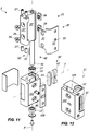
FIGS. 1 is an exploded view of an embodiment of thehinge 1; -
FIGS. 2a and 2b are perspective views of the embodiment of thehinge 1 ofFIG. 1 respectvely in the closed and open position; -
FIGS. 3a and 3b are respectively perspective and upper views of the embodiment of thehinge 1 ofFIG 1 in which themovable element 20 is mounted on a door D and thefixed element 10 is mounted on a frame F, the door D being in the closed position; -
FIGS. 3c and 3d are respectively perspective and upper views of the embodiment of thehinge 1 ofFIG 1 in which themovable element 20 is mounted on a door D and thefixed element 10 is mounted on a frame F, the door D being in the open position; -
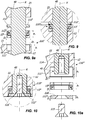
FIG. 4 is a schematic view of the assembly pivot 40 - cam 51 - interface element 62 -elastic counteracting element 61 to be used in the embodiment of thehinge 1 ofFIG. 1 ; -
FIGS. 5 and 6 are respectively side views of a first embodiment of theinterface element 62 and thepivot 40 to be used in the embodiment of thehinge 1 ofFIG. 1 ; -
FIGS. 7a and 7b are side views of a second embodiment of thepivot 40 to be used in the embodiment of thehinge 1 ofFIG. 1 ; -
FIG. 7c is a side view of a second embodiment of theinterface element 62 to be used in the embodiment of thehinge 1 ofFIG. 1 ; -
FIGS. 8a, 8b and 8c are respective top view and views sectioned along a plane VIIIb - VIIIb and along a plane VIIIc - VIIIc of the embodiment of thehinge 1 ofFIG. 1 , the hinge being in the closed position; -
FIG. 9 is an enlarged view of some details ofFIG. 8b , with inFIG. 9a an exploded view of such details; -
FIG. 10 is an enlarged view of further details ofFIG. 8b , with inFIG. 10a an exploded view of such details; -
FIG. 11 is an exploded perspective view of a further embodiment of thehinge 1, in which the box-shaped hinge body 11 is integral with thebackplate 102; -
FIG. 12 is a perspective view of thehinge body 11 of the embodiment of thehinge 1 ofFIG. 11 ; -
FIGS. 13a and 13b are respectively perspective and sectional partly cut views of some details of a further embodiment of the cam means 50 and the follower means 60, embodiment which does not form part of the invention; -
FIGS. 14 to 19 are sectional views of the cam means 50 and follower means 60 ofFIGS. 13a and 13b in various operational steps, in which for each step the relative position of the cam means 50, the pushing member 68' and theelastic counteracting element 61 is enlargedly shown. - With reference to the above figures, the hinge according to the invention, generally indicated 1, is particularly useful for the rotatable possibly controlled movement during opening and/or closing of a closing element D, such as a reinforced door, which may be anchored to a stationary support structure, such as a wall, a floor or a ceiling.
- Suitably, the
hinge 1 may be concealedly inserted in a tubular support structure, which may be formed in a per se known manner by a rear counterframe CF, which can be anchored to the wall W or like support, and by a front frame F anchored to the counterframe CF. - In particular, the
hinge 1 can be configured as a concealed "Anuba" hinge anchored to the frame F by the plate P2. - Advantageously, the
hinge 1 is concealedly insertable in the support structure formed by the tubular rear counterframe CF and the front frame F. - Conveniently, the
hinge 1 includes afixed element 10 to be fixed to the stationary support W, for example by the frame F or the counterframe CF, on which amovable element 20 is pivoted to rotate about a longitudinal axis X, which may be substantially vertical, between an open position and a closed position. - In particular, the
hinge 1 consists of a lower fixed half-hinge 10 and a movable upper half-hinge 20 rotatably coupled each other to rotate between the open and closed positions about the axis X. - Advantageously, the lower fixed half-
hinge 10 includes a box-shaped hinge body 11 anchored to the stationary support W, while the movable upper half-hinge 20 includesmeans 21 for fixing to the door D. - Suitably, the
hinge body 11 may be concealedly insertable within the support structure formed by the tubular rear counterframe CF and the front frame F, while the connectingmeans 21 is defined by a connecting plate susceptible to extend from the tubular support structure in the open position of the door D, as shown for example inFIGS. 3c and 3d , and to retract within the same tubular support structure in the closed position of the door D, as shown for example inFIGS. 3a and 3b . - In particular, the connecting
plate 21 of thehinge 1 is rotatably connected to thebody 11 by means of thehinge pivot 40, which will be better described later. - Advantageously, the box-shaped
hinge body 11 includes a passing-throughseat 12 defining the axis X within which is inserted with minimal clearance thepivot 40, which may be unitary connected to the connectingplate 21. - In this way, the
pivot 40 is unitary movable with the door D between the open and closed positions. Thanks to this feature, thehinge 1 is able to support even very heavy doors D without misalignments or changing of the behaviour. - Suitably, at the ends of the passing-through
seat 12 of the box-shapedbody 11 respectiveanti-friction elements 13 may be placed, such as bearings. This allows themovable element 20 to rotate about the axis X with minimum friction, so that thehinge 1 is able to support even very heavy doors D. - The
hinge body 11 includes internally a working chamber 14 defining a second axis Y which is substantially perpendicular to the first axis X defined by the passing-throughseat 12 for thepivot 40. - Suitably, the
pivot 40 includes cam means 50 rotating around the axis X, while the working chamber 14 includes follower means 60 interacting with the former to slidably move along the axis Y between a first and a second end-stroke position, corresponding for example to the open and closed door D position. - The follower means 60 includes an elastic counteracting element susceptible to elastically oppose the pushing force imparted by the cam means. As non-limiting example, the elastic counteracting element may include, respectively may consist of, a spring, a nitrogen cylinder or a portion of polymeric material.
- In a preferred but not exclusive embodiment of the
hinge 1, the elastic counteracting element may consist of anelastomer body 61, which may be plate-shaped, disk-shaped or cylindrical-shaped. - Advantageously, the
elastomer body 61 may be made of a polyurethane elastomer of the compact type, for example Vulkollan®. Suitably, the elastomer may have a Shore A hardness of 50 ShA to 95 ShA, preferably of 70 ShA to 90 ShA. More preferably, theelastomer body 61 may have a Shore A hardness of 80 ShA. - The use of the elastomer in place of the classic spring allows to have a very high braking force, in a very small space. In fact, the stroke of the
elastomer body 61 along the axis Y may be of some millimeters, for example 2-4 mm. - Moreover, the
elastomer body 61 allows to obtain a braking effect of great efficiency in a purely mechanical hinge without the use of oil or like hydraulic damping means, for example during the opening. - In fact, upon the opening of the door D the
elastic counteracting element 61 passes from the first to the second end-stroke position and remains in this position until the closing of the door by a user, so that thehinge 1 is a control hinge braked during opening. - Moreover, the follower means 60 includes an
interface element 62 having a first end 63' which interacts with theelastic counteracting element 61 and asecond end 63" interacts with the cam means 50. - Advantageously, the
interface element 62 may have a substantially "C"- shape with a centralelongated portion 64 defining a third longitudinal axis Z substantially parallel to the axis X and perpendicular to the axis Y and a pair of endtransverse appendices 65', 65" substantially perpendicular to the axis X and parallel to the axis Y. - Both the elongated
central portion 64 and the endtransverse appendices 65', 65" may include respective operating surfaces 66, 67', 67" placed at thefront end 63", the function of which is better explained later. - Moreover, the
pivot 40 includes the cam means 50, so that the latter rotate unitary with the former around the axis X. - More particularly, in the
pivot 40 ofFIGs. 4 and 6 the cam means 50 may include a single cam element, while in thepivot 40 ofFIGs. 7a and 7b the cam means 50 may include two cam elements. According to the invention, the single cam element is defined by a plate-shapedbody 51 insertable transversely in a removable manner within aseat 42 of thepivot 40 so that a portion of the former extends from the latter. This configuration simplifies the assembly of thehinge 1. - Suitably, the plate-shaped
body 51 may have a frontperipheral edge 53 susceptible to interact with theinterface element 62, for example in correspondence of the operatingsurface 66. To this end, the frontperipheral edge 53 may be appropriately rounded. - In this way, the
interface element 62 progressively compresses theelastomer body 61 upon the opening of the door D. Theelastomer body 61 may further be susceptible to remain in the configuration elastically deformed until the closing of the door D by a user. In other words, thehinge 1 is elastically braking upon opening. - Suitably the
hinge 1 may be configured so that thecam element 51 interacts with the operatingsurface 66 after an angular rotation of the door D, for example 45°. Following interaction with theinterface element 62, thecam element 51 compresses theelastomer body 61, so that the hinge is mechanically braked upon opening during the subsequent angular rotation, for example the next 45°. In other words, the first angular rotation is free, that is not braked, while the subsequent angular rotation is braked by the braking action of theelastomer body 61. - In one preferred but not exclusive embodiment, two cam elements may be provided, in particular a pair of
first cam elements 52', 52" susceptible to interact with the operating surfaces 67', 67" of theinterface element 62 and a second cam element consisting of the plate-shapedelement 51 which is susceptible to interact with the operatingsurface 66. - The
first cam elements 52', 52" may be defined by a pair of substantially flat faces formed on theouter surface 44 of thepivot 40, in longitudinally staggered positions so as to be operatively in contact with the operatingplanar surfaces 67', 67" of theinterface element 62. - Conveniently, the cam means 50 and the follower means 60 may be configured so that the substantially flat faces 52', 52" and the operative surfaces 67', 67" are substantially parallel and in mutual contact when the door D is in the closed position, as shown for example in
FIGS 11a to 11d , and are substantially perpendicular and spaced apart each other when the door D is in the open position, as shown for example inFIGS 13a to 13d . - The plate-shaped
element 51 may further define a plane π substantially perpendicular to the substantially planar faces 52', 52". - In this way, it is possible to achieve a full control on the door D upon the opening, throughout all the angular rotation thereof.
- In fact, for a first portion of angular rotation the substantially flat faces 52', 52" and the operative surfaces 67', 67" interact with each other to partially compress the
elastomeric body 61, thus urging it from the rest or starting stroke position to an intermediate compressed position. Further, for the next portion of the angular rotation of the door D the plate-shapedelement 51 and the operatingsurface 66 of theinterface element 62 interact each other so as to further compress theelastomeric body 61, thus compressing it from the intermediate compressed position to the totally compressed or end stroke position. - This allows to progressively compress the elastic element, so as to obtain a braking effect for the entire angular rotation of the door D.
- In another embodiment, which does not form part of the invention, shown for example in the
FIGs. 13a to 19 , theinterface element 62 may be configured as a pushing member 68' and include aprotrusion 300, having a generally hemispherical shape. On the other hand, the cam means 50 may include a plurality ofseats - More in particular, the
seats protrusion 300 to supper the door in the supper positions. - Suitably, the
seat 310 may correspond to the closed door position, while theseats seat 310 corresponding to the closed door position may have a generally "V"-shape with twoconsecutive planes - In this way, as particularly shown in
FIG. 15 , the sliding of thehemispherical protrusion 300 on theplanes - At the same time, the user can rotate the door from the closed door position in both opening directions.
- To maximize this effect, the angle between the
planes planes - Moreover, each of the
seats consecutive portions - The
first portions 322; 332 may be generally flat, while thesecond portions 321; 331 may be countershaped with respect to the shape of theprotrusion 300, and in particular may be hemispherical. - In this way, the first
flat portions 322; 332 may promote the sliding of theprojection 310 thereon to convey it towards thesecond portions 321; 331, suitable to supper the door. - In this way, as particularly shown in
FIG. 16 , the automatic opening of the door starting from a predetermined angle, for example 70°, is ensured. - As particularly shown in
FIG. 17 , the firstflat portions 322; 332 act as pilot members for the secondhemispherical portions 321; 331, so that the insertion of theprotrusion 300 in the latter takes place without noise. - Advantageously, the first
flat portions 322; 332 may be substantially perpendicular to theplanes - Moreover, thanks to the above configuration the door may be rotated from the supper position only in one direction. In other words, the rotation in the other direction is prevented.
- Indeed, as particularly shown in
FIG. 19 , if a user attempts to further rotate the door, the momentum caused by theelastic counteracting element 61 opposes this force, which momentum urges the one against the other theprotrusion 300 and thesecond portions 321; 331. - Suitably, the
elastic counteracting element 61 may be configured so as to allow a further slight rotation of the door after the supper position in the door open position. To this end, theelastic counteracting element 61 after this minimum rotation can reach the position of maximum compression. - This absorbs the shock undergone by the door upon the reaching of the supper position. This configuration is particularly advantageous in the case of glass door, which in the case of abrupt shock could be damaged or broken.
- The embodiment of the cam means 50 and the follower means 60 shown in
FIGs. 13a to 19 and described above is particularly advantageous with the above describedelastic counteracting element 61 made of elastomer. - In fact, in the latter a minimum stroke corresponds to a very high strength.
- Therefore, suitably precompressing the
elastic counteracting element 61 in the working chamber 14 the strength of thehinge 1 is maximized. - Also, the
elastic counteracting element 61 made of elastomer maximizes the effect of stopping the rotation, as described above. - In one preferred but not exclusive embodiment, it is possible to adjust the opening angle of the door D.
- For the purpose, an adjusting
screw 80 may be provided transversely inserted in thehinge body 11 with a first operating end 81 accessible by a user to adjust the penetration of the former 80 through the corresponding wall of the latter 11 and an opposite end 82 susceptible to come into contact with the plate-shapedelement 51. - By appropriately acting on the operating end 81 of the
screw 80 the opening angle of the door can be adjusted in a simple and rapid manner, so as to avoid any impact of the door D against the stationary support W. - The
hinge 1 is extremely effective and performing, and is also greatly simple to assemble. - For example, the
hinge body 11 may have, in addition to the passing-throughseat 12 for containing thepivot 40, a passing-through opening 16 to make accessible the working chamber 14 from the outside. - In particular, the passing-through opening 16 may be susceptible to allow the insertion within the working chamber 14 of both the follower means 60 and the cam means 50, in particular of the plate-shaped
element 51. - The passing-through opening 16 defines an axis Y' perpendicular to both the axis Y and the axis X.
- In practice, both the cam means 50 and the follower means 60 may be removably inserted in the working chamber 14 by sliding along the axis Y'.
- This is particularly advantageous if it is necessary to change the
elastic element 61, for example to insert a softer or harder one in order to vary the braking action of thehinge 1, or to change the plate-shapedelement 51, for example to insert one of different configuration to vary the braking action of thehinge 1. - In fact, in order to mount the cam means 50 and the follower means 60, it is simply needed to insert within the working chamber 14 through the passing-through opening 16 the
elastic counteracting element 61 and theinterface element 62, subsequently to insert thepivot 40 into theseat 12 and then rotate the latter to move theseat 42 thereof in correspondence of the same passing-through opening 16, so as to allow the insertion of the plate-shapedelement 51. The dismounting thereof may occur in the reverse order. - The
hinge 1, in addition to the above mentioned features and advantages, is particularly advantageous because it is possible to adjust the position of the door D in the three dimensions, that is both in height and in a plane substantially parallel to the floor as shown for example inFIG. 3c . - In fact, the connecting
plate 21 may include a first portion 25' susceptible to receive thepivot 40 and asecond portion 25" susceptible to receive the mountingbracket 30 and to allow the adjustment along the directions d, d', as shown inFIG. 2b . - Suitably, the mounting
bracket 30 may have afirst plate portion 31 operatively fixable to the first portion 25' of the mounting body 24 monolithically coupled with asecond plate portion 32, connectable in turn to the door D by means of suitable screws insertable into theholes 33. - The operational connection between the first portion 25' of the mounting body 24 and the
first plate portion 31 of the mountingbracket 30 may be made by means ofsuitable screws 34 inserted through theholes 26 of the mounting body 24 and theopenings 35 of the mountingbracket 30 and lockable insuitable locking elements 36. - By suitably operating on the
screws 34 it is possible to move the mountingbracket 30, and then the door D, along the direction d'. In fact, by appropriately unscrewing thescrews 34 it is possible to move the mountingbracket 30 for a stroke equal to the length L of theopenings 35 in which thescrews 34 are inserted. - The movement along the vertical direction d is ensured by the
screws 37', 37" inserted through thesecond portion 25" of the connectingplate 21, thefirst plate portion 31 of themunting bracket 30 lying therebetween. As mentioned above, the latter is secured to the former by using thescrews 34. - The
screws 37', 37" can be operated by unscrewing thescrews 34, that allow the movement of the mountingbracket 30 with a stroke equal to the height H of theopenings 35 in which thescrews 34 are inserted. - To enable movement of the
hinge 1 along the direction d", thehinge body 11 may be movably mounted on ananchor plate 100, which may be anchored to the tubular support structure F, CF by using thescrews 101. - To this end, a
backplate 102 may be provided, which may be coupled to thehinge body 11 by means ofscrews 103 to define aninterspace 104 therebetween, in which interspace theanchor plate 100 is housed. Theinterpace 104 may include two side abutment surfaces 105', 105". - In the alternative embodiment shown in
FIGS. 11 and 12 , thebackplate 102 may be integrated into thehinge body 11, i.e. the two parts can be made in a single piece. This allows to provide a moreeconomic hinge 1. - The
screws 101 are engageable in theanchor plate 100 by passing through theslots 106 of thebackplate 102. - By appropriately acting on the
screws 101 it is possible to move the assembly of thehinge body 11 and thebackplate 102, and then the door D, along the direction d". In fact, by suitably unscrewing thescrews 101, it is possible to move the assembly between thehinge body 11 and thebackplate 102, and hence thehinge 1, for a stroke equal to the length L' of theslots 106 in which thescrews 101 are inserted and/or the distance between the side abutment surfaces 105', 105" of theinterspace 104. - The
hinge 1 may further be designed to minimize friction between the fixed half-hinge 10 and the movable half-hinge 20. - For this purpose, the upper end 110' of the
seat 12 may include a respective upper annular housing 111' suitable to receive a respective upper antifriction element 13', such as a bearing. - As particularly shown in
FIGS. 17d and 17e , thepivot 40 may include a upper radial expansion 112', for example a flange, with an upper operating surface 113' susceptible to come in contact with the connectingplate 21 and alower operating surface 113" susceptibleto remain faced to the upper annular housing 111'. - Advantageously, the upper annular housing 111' and the upper antifriction element 13' may be mutually configured so that the
lower operating surface 113" of the upper radial expansion 112' is susceptible to abut against the upper antifriction element 13'. In this way, thepivot 40 can rotate onto the upper antifriction element 13' by remaining mutually spaced from thehinge body 11. - To this end, the inner diameter D1 of the upper annular housing 111' may be substantially equal to the outer diameter D2 of the upper antifriction element 13', while the height h2 of the latter may be slightly greater than the height h1 of the former, for example a few tenths of a millimeter.
- Furtherly, the
lower end 110" of theseat 12 suitably includes a lowerannular housing 111" susceptible to receive a respectivelower antifriction element 13". - The
lower end 41 of thepivot 40 may include a blindaxial hole 114 susceptible to receive a lockingscrew 115. Apressure element 112" may further be provided, for example a washer, susceptible to be interposed between the lockingscrew 115 and thelower antifriction element 13" to define a lower radial expansion. Advantageously, the latter may include an upperoperative surface 116 susceptible to remain faced to the lowerannular housing 111". - The latter, the
lower antifriction element 13" and thepivot 40 may be mutually configured so that the upperoperative surface 116 of thepressure element 112" is susceptible to abut against thepivot 40 and to remain spaced apart from thelower antifriction element 13". - In this way, the possible reaction forces due to the rotation of the
pivot 40 at itslower end 41 is loaded on thelower antifriction element 13". - This prevents the slipping of the
pivot 40 from theseat 12 and/or the misalignment of thesame pivot 40. - To minimize friction between the lower fixed half-
hinge 10 and the upper half-hinge 20, the inner diameter D3 of the lowerannular housing 111" may be substantially equal to the outer diameter D4 of thelower antifriction element 13", while the outer diameter D5 of thepressure element 112" may be slightly less than the inner diameter D3 of the lowerannular housing 111". - Moreover, the height h3 of the latter may suitably be substantially equal to the sum of the height h4 of the
lower antifriction element 13" and the height h5 of thepressure element 112". - Advantageously, the upper and
lower antifriction elements 13', 13" may consist of bearings of the axial-radial type, in order to suitably load thereon both the axial and the radial stresses due to the weight of the door D and/or their reactions forces. - From the above description, it is apparent that the
hinge 1 fulfils the intended objects. - The
hinge 1 is susceptible to many changes and variants. All particulars may be replaced by other technically equivalent elements, and the materials may be different according to the needs, without exceeding the scope of the invention defined by the appended claims.
Claims (13)
- A concealed hinge for rotatable moving a door (D), in particular a reinforced door, connected to a tubular support structure (F, CF) which includes a rear counterframe (CF) anchored to a wall (W) or a similar support and a front frame (F) anchored to the counterframe (CF), the hinge comprising a lower fixed half-hinge (10) and an upper movable half-hinge (20) rotatably coupled each other for rotating about a first longitudinal axis (X) between an open position and a closed position;
wherein said lower fixed half-hinge (10) includes a box-shaped hinge body (11) to be concealed within the tubular support structure (F, CF) and anchorable thereto, said upper movable half-hinge (20) including a pivot (40) defining said first axis (X) and a connecting plate (21) anchorable to the door (D), connecting plate (21) being reciprocally connected with said pivot (40) to extend from the tubular support structure (F, CF) in said open position and to concealedly retract within the tubular support structure (F, CF) in said closed position;
wherein said box-shaped hinge body (11) includes a seat (12) internally housing said pivot (40),
characterized in that the pivot includes cam means (50) rotating about said first longitudinal axis (X), said box-shaped hinge body (11) further including at least one working chamber (14) defining a second longitudinal axis (Y) substantially perpendicular to said first axis (X), said at least one working chamber (14) including follower means (60) interacting with said cam means (50) for sliding along said second longitudinal axis (Y) between a first and a second end-stroke position, said follower means (60) including at least one elastic counteracting element (61);
wherein said cam means (50) of said pivot (40) includes at least one elongated appendix (51) transversely extending with respect to said first axis (X) to rotate within said seat (12), said follower means (60) including at least one interface element (62) having a first end (63') interacting with said at least one elastic counteracting element (61) and a second end (63") interacting with said at least one elongated appendix (51);
wherein said elongate appendix (51) is defined by a plate-shaped element removably insertable into a seat (42) of said pivot (40). - Hinge according to claim 1, wherein said elongate appendix (51) defines a plane (π) substantially parallel to said first axis (X) and substantially perpendicular to said second axis (Y).
- Hinge according to claim 1 or 2, wherein said box-shaped hinge body (11) has at least one passing-through opening (16) to allow insertion/removal of said plate-shaped element (51) in/from said seat (42) of said pivot (40) when the latter is mounted within the respective seat (12).
- Hinge according to claim 3, wherein said passing-through opening (16) allows the insertion/removal of both said plate-shaped element (51) in/from said seat (42) and the follower means (60) in/from the working chamber (14).
- Hinge according to claim 4, wherein said seat (42) of said pivot (40), said working chamber (14) and said at least one passing-through opening (16) are reciprocally configured in such a manner that the mounting of said cam means (50) and said follower means (60) occurs by at first inserting said follower means (60) within said working chamber (14) through said passing-through opening (16), subsequently by inserting the pivot (40) into said seat (12) and then by rotating the latter to move the seat (42) thereof in correspondence of said passing-through opening (16), so as to allow a user to insert said plate-shaped element (51).
- Hinge according to one or more of the preceding claims, wherein said box-shaped hinge body (11) further comprises at least one abutment screw (80) having a first operating end (82) lying within said seat (12) for abutting against said elongated appendix (51) of said pivot (40) and a second operating end (81) accessible from outside by a user to adjust the penetration of said at least one abutment screw (80) within said seat (12), so as to adjust the opening and/or closing angle of the hinge.
- Hinge according to claim 6, wherein said at least one abutment screw (80) is transversely inserted within the hinge body (11) with respect to said first axis (X), said elongated appendix (51) defining a plane (π) with at least one side wall (54) susceptible to impact against said first operating end (82) of said at least one abutment screw (80).
- Hinge according to one or more of the preceding claims, wherein said at least one elastic counteracting element (61) includes, respectively consists of, at least one portion of elastically deformable polymeric material.
- Hinge according to claim 8, wherein said elastic counteracting element (61) consists of a body made of polymeric material.
- Hinge according to claim 9, wherein said body of elastically deformable polymeric material has a cylindrical or disk-like or plate-shaped shape.
- Hinge according to one or more of the claims 8 to 10, wherein said polymeric material consists of an elastomer.
- Hinge according to claim 11, wherein said elastomer is polyurethane of the compact type.
- Hinge according to claim 11 or 12, wherein said elastomer has a Shore A hardness of 50 ShA to 95 ShA, preferably of 70 ShA to 90 ShA.
Priority Applications (1)
| Application Number | Priority Date | Filing Date | Title |
|---|---|---|---|
| EP17195715.2A EP3306022A1 (en) | 2013-04-12 | 2014-04-11 | Concealed hinge for the controlled rotatable movement of a door, in particular a reinforced door |
Applications Claiming Priority (3)
| Application Number | Priority Date | Filing Date | Title |
|---|---|---|---|
| IT000101A ITVI20130101A1 (en) | 2013-04-12 | 2013-04-12 | HINGE FOR THE TURNTABLE HANDLING OF A DOOR |
| IT000106A ITVI20130106A1 (en) | 2013-04-12 | 2013-04-12 | HINGE FOR THE TURNTABLE HANDLING OF A DOOR |
| PCT/IB2014/060661 WO2014167546A2 (en) | 2013-04-12 | 2014-04-11 | Concealable hinge for the controlled rotatable movement of a door, in particular a reinforced door |
Related Child Applications (1)
| Application Number | Title | Priority Date | Filing Date |
|---|---|---|---|
| EP17195715.2A Division EP3306022A1 (en) | 2013-04-12 | 2014-04-11 | Concealed hinge for the controlled rotatable movement of a door, in particular a reinforced door |
Publications (2)
| Publication Number | Publication Date |
|---|---|
| EP2984263A2 EP2984263A2 (en) | 2016-02-17 |
| EP2984263B1 true EP2984263B1 (en) | 2017-10-11 |
Family
ID=50884961
Family Applications (2)
| Application Number | Title | Priority Date | Filing Date |
|---|---|---|---|
| EP17195715.2A Withdrawn EP3306022A1 (en) | 2013-04-12 | 2014-04-11 | Concealed hinge for the controlled rotatable movement of a door, in particular a reinforced door |
| EP14728296.6A Active EP2984263B1 (en) | 2013-04-12 | 2014-04-11 | Concealable hinge for the controlled rotatable movement of a door, in particular a reinforced door |
Family Applications Before (1)
| Application Number | Title | Priority Date | Filing Date |
|---|---|---|---|
| EP17195715.2A Withdrawn EP3306022A1 (en) | 2013-04-12 | 2014-04-11 | Concealed hinge for the controlled rotatable movement of a door, in particular a reinforced door |
Country Status (6)
| Country | Link |
|---|---|
| US (1) | US9422756B2 (en) |
| EP (2) | EP3306022A1 (en) |
| CA (1) | CA2908308C (en) |
| EA (1) | EA030890B1 (en) |
| ES (1) | ES2654213T3 (en) |
| WO (1) | WO2014167546A2 (en) |
Families Citing this family (6)
| Publication number | Priority date | Publication date | Assignee | Title |
|---|---|---|---|---|
| US9605457B2 (en) * | 2008-10-29 | 2017-03-28 | Steven Humble | Three-dimensionally adjustable pivot device |
| WO2014167545A2 (en) * | 2013-04-12 | 2014-10-16 | In & Tec S.R.L. | Hinge for the controlled rotatable movement of a door |
| ITUB20153873A1 (en) * | 2015-09-24 | 2017-03-24 | Mgt Ind S R L | REFINED HINGE FOR SWIVEL DOORS, ESPECIALLY OF SHOWER ENCLOSURES |
| ITUB20160495A1 (en) * | 2016-02-03 | 2017-08-03 | Tubes Radiatori S R L | MODULAR RADIATOR STRUCTURE FOR ROOM HEATING |
| CN108678582B (en) * | 2018-06-21 | 2023-05-02 | 广东东泰五金精密制造有限公司 | Anti-displacement movable positioning structure of furniture overturning device |
| AT17584U1 (en) * | 2021-03-17 | 2022-07-15 | Roto Frank Fenster Und Tuertechnologie Gmbh | Tape for a door or window |
Family Cites Families (24)
| Publication number | Priority date | Publication date | Assignee | Title |
|---|---|---|---|---|
| FR1586435A (en) * | 1968-08-22 | 1970-02-20 | ||
| DE2035597A1 (en) * | 1969-07-17 | 1971-02-04 | Hansen, Carl A , Goransson Gote L , Bethel, Conn (V St A ) | Heavy-duty double joint hinge |
| DE2356166A1 (en) * | 1973-11-09 | 1975-05-15 | Juergen Disput | Ball bearing adjustable door hinge - has screws for adjusting lateral and vertical relative positions of door |
| DE3014087A1 (en) * | 1980-04-12 | 1981-10-15 | Friedrich 8500 Nürnberg Puchtler | Triple roller door hinge strip pin - has axial groove aligning with securing pin at prescribed opening angle |
| IT1192109B (en) * | 1985-10-22 | 1988-03-31 | Otlav Spa | HINGE WITH PRESET STABLE POSITIONS |
| US5075928A (en) | 1990-08-17 | 1991-12-31 | The Stanley Works | Concealed architectural hinge assembly |
| US5799370A (en) * | 1996-06-12 | 1998-09-01 | The Stanley Works | Adjustable hinge |
| DE19623539B4 (en) * | 1996-06-13 | 2010-06-24 | KL-Beschläge Karl Loggen GmbH | wrist strap |
| IT248724Y1 (en) * | 1999-06-25 | 2003-02-12 | Koblenz Spa | CONCEALED HINGE, IN PARTICULAR FOR DOORS AND / OR FOR FURNITURE DOORS. |
| US6430779B1 (en) * | 2000-03-31 | 2002-08-13 | Modernfold, Inc. | Mounting apparatus for concealed hinge of operable wall |
| ES2335866T3 (en) * | 2001-10-31 | 2010-04-06 | Simonswerk, Gesellschaft Mit Beschrankter Haftung | DOOR HINGE FOR A HIDDEN PROVISION BETWEEN THE FENCE OF THE DOOR AND THE LEAF OF THE DOOR. |
| ES2404306T3 (en) * | 2004-06-03 | 2013-05-27 | Roto Gluske-Bkv Gmbh | Frame pernio |
| US8234753B2 (en) * | 2008-10-24 | 2012-08-07 | L-3 Communications Integrated Systems L.P. | Cook hinge |
| IT1391640B1 (en) | 2008-10-28 | 2012-01-17 | Omf S R L | ADJUSTMENT DEVICE FOR RETRACTABLE HINGES AND RETRACTABLE HINGES INCLUDING THE ADJUSTMENT DEVICE |
| DE102008057341B3 (en) * | 2008-11-14 | 2009-12-31 | Simonswerk, Gesellschaft mit beschränkter Haftung | Door hinge for concealed arrangement between door frame and door leaf |
| IT1393499B1 (en) * | 2009-03-27 | 2012-04-27 | Evi Srl Unipersonale Ora Evi S R L | HINGE FOR DOORS, WINDOWS AND THE LIKE. |
| DE102010012574B3 (en) * | 2010-03-23 | 2011-05-12 | Simonswerk, Gesellschaft mit beschränkter Haftung | Band for plastic door and plastic window, has two rotary joint connected band pieces and band receiving element which has housing for fastening at door frame or window frame and attachment unit for band piece |
| GB2484527B (en) * | 2010-10-14 | 2015-05-20 | Chung Chow | Hinge having self centering means |
| DE102011000150B3 (en) * | 2011-01-14 | 2011-10-06 | Simonswerk, Gesellschaft mit beschränkter Haftung | Door hinge for convertible arrangement between door frame and door wing of door, has door wing-receiving body which is inserted in recess in narrow side of door wing |
| DE102011050413B3 (en) * | 2011-05-17 | 2012-04-12 | Simonswerk, Gesellschaft mit beschränkter Haftung | Door hinge for a concealed arrangement between the door leaf and the door frame |
| EP2570575B1 (en) * | 2011-09-16 | 2016-09-07 | Koblenz S.P.A. | A fully concealed hinge with integrated closing device for doors and/or openable furniture parts |
| DE102012101644B3 (en) * | 2012-02-29 | 2012-10-18 | Simonswerk, Gesellschaft mit beschränkter Haftung | Door hinge for concealed arrangement between frame and leaf of e.g. right hinged door in furniture, has fastening part with space exhibiting stage form with stages above and below hinge bracket, where form is adjusted to length of brackets |
| ES2663261T3 (en) * | 2012-07-04 | 2018-04-11 | In & Tec S.R.L. | Hinge to rotatably move a door, in particular a reinforced door |
| WO2014167545A2 (en) * | 2013-04-12 | 2014-10-16 | In & Tec S.R.L. | Hinge for the controlled rotatable movement of a door |
-
2014
- 2014-04-11 EP EP17195715.2A patent/EP3306022A1/en not_active Withdrawn
- 2014-04-11 EA EA201591963A patent/EA030890B1/en not_active IP Right Cessation
- 2014-04-11 EP EP14728296.6A patent/EP2984263B1/en active Active
- 2014-04-11 ES ES14728296.6T patent/ES2654213T3/en active Active
- 2014-04-11 WO PCT/IB2014/060661 patent/WO2014167546A2/en active Application Filing
- 2014-04-11 CA CA2908308A patent/CA2908308C/en active Active
-
2015
- 2015-10-11 US US14/880,255 patent/US9422756B2/en active Active
Non-Patent Citations (1)
| Title |
|---|
| None * |
Also Published As
| Publication number | Publication date |
|---|---|
| ES2654213T3 (en) | 2018-02-12 |
| US9422756B2 (en) | 2016-08-23 |
| EA201591963A1 (en) | 2016-04-29 |
| EP3306022A1 (en) | 2018-04-11 |
| WO2014167546A3 (en) | 2015-03-12 |
| EA030890B1 (en) | 2018-10-31 |
| EP2984263A2 (en) | 2016-02-17 |
| WO2014167546A2 (en) | 2014-10-16 |
| US20160060930A1 (en) | 2016-03-03 |
| CA2908308A1 (en) | 2014-10-16 |
| CA2908308C (en) | 2021-04-06 |
Similar Documents
| Publication | Publication Date | Title |
|---|---|---|
| US9422756B2 (en) | Concealable hinge for the controlled rotatable movement of a door, in particular a reinforced door | |
| EP2984267B1 (en) | Hinge for the controlled rotatable movement of a door, in particular a glass door | |
| US9657507B2 (en) | Hinge for the controlled rotatable movement of a door | |
| US10151129B2 (en) | Low-bulkiness hydraulic hinge | |
| WO2012143812A2 (en) | Hinge device for doors, shutters or the like | |
| US9926733B2 (en) | Low bulkiness hinge | |
| US20160369542A1 (en) | Concealable hinge for the controlled rotatable movement of a door, in particular a reinforced door | |
| US11261637B2 (en) | Hinge for the rotatable movement of a door, a shutter or the like | |
| KR101909911B1 (en) | Hinge apparatus for door |
Legal Events
| Date | Code | Title | Description |
|---|---|---|---|
| PUAI | Public reference made under article 153(3) epc to a published international application that has entered the european phase |
Free format text: ORIGINAL CODE: 0009012 |
|
| 17P | Request for examination filed |
Effective date: 20151112 |
|
| AK | Designated contracting states |
Kind code of ref document: A2 Designated state(s): AL AT BE BG CH CY CZ DE DK EE ES FI FR GB GR HR HU IE IS IT LI LT LU LV MC MK MT NL NO PL PT RO RS SE SI SK SM TR |
|
| AX | Request for extension of the european patent |
Extension state: BA ME |
|
| DAX | Request for extension of the european patent (deleted) | ||
| GRAP | Despatch of communication of intention to grant a patent |
Free format text: ORIGINAL CODE: EPIDOSNIGR1 |
|
| INTG | Intention to grant announced |
Effective date: 20170418 |
|
| GRAS | Grant fee paid |
Free format text: ORIGINAL CODE: EPIDOSNIGR3 |
|
| GRAA | (expected) grant |
Free format text: ORIGINAL CODE: 0009210 |
|
| AK | Designated contracting states |
Kind code of ref document: B1 Designated state(s): AL AT BE BG CH CY CZ DE DK EE ES FI FR GB GR HR HU IE IS IT LI LT LU LV MC MK MT NL NO PL PT RO RS SE SI SK SM TR |
|
| REG | Reference to a national code |
Ref country code: GB Ref legal event code: FG4D |
|
| REG | Reference to a national code |
Ref country code: CH Ref legal event code: EP |
|
| REG | Reference to a national code |
Ref country code: IE Ref legal event code: FG4D |
|
| REG | Reference to a national code |
Ref country code: AT Ref legal event code: REF Ref document number: 936201 Country of ref document: AT Kind code of ref document: T Effective date: 20171115 |
|
| REG | Reference to a national code |
Ref country code: DE Ref legal event code: R096 Ref document number: 602014015683 Country of ref document: DE |
|
| REG | Reference to a national code |
Ref country code: ES Ref legal event code: FG2A Ref document number: 2654213 Country of ref document: ES Kind code of ref document: T3 Effective date: 20180212 |
|
| REG | Reference to a national code |
Ref country code: NL Ref legal event code: MP Effective date: 20171011 |
|
| REG | Reference to a national code |
Ref country code: LT Ref legal event code: MG4D |
|
| REG | Reference to a national code |
Ref country code: AT Ref legal event code: MK05 Ref document number: 936201 Country of ref document: AT Kind code of ref document: T Effective date: 20171011 |
|
| REG | Reference to a national code |
Ref country code: FR Ref legal event code: PLFP Year of fee payment: 5 |
|
| PG25 | Lapsed in a contracting state [announced via postgrant information from national office to epo] |
Ref country code: NL Free format text: LAPSE BECAUSE OF FAILURE TO SUBMIT A TRANSLATION OF THE DESCRIPTION OR TO PAY THE FEE WITHIN THE PRESCRIBED TIME-LIMIT Effective date: 20171011 |
|
| PG25 | Lapsed in a contracting state [announced via postgrant information from national office to epo] |
Ref country code: SE Free format text: LAPSE BECAUSE OF FAILURE TO SUBMIT A TRANSLATION OF THE DESCRIPTION OR TO PAY THE FEE WITHIN THE PRESCRIBED TIME-LIMIT Effective date: 20171011 Ref country code: NO Free format text: LAPSE BECAUSE OF FAILURE TO SUBMIT A TRANSLATION OF THE DESCRIPTION OR TO PAY THE FEE WITHIN THE PRESCRIBED TIME-LIMIT Effective date: 20180111 Ref country code: LT Free format text: LAPSE BECAUSE OF FAILURE TO SUBMIT A TRANSLATION OF THE DESCRIPTION OR TO PAY THE FEE WITHIN THE PRESCRIBED TIME-LIMIT Effective date: 20171011 Ref country code: FI Free format text: LAPSE BECAUSE OF FAILURE TO SUBMIT A TRANSLATION OF THE DESCRIPTION OR TO PAY THE FEE WITHIN THE PRESCRIBED TIME-LIMIT Effective date: 20171011 |
|
| PG25 | Lapsed in a contracting state [announced via postgrant information from national office to epo] |
Ref country code: HR Free format text: LAPSE BECAUSE OF FAILURE TO SUBMIT A TRANSLATION OF THE DESCRIPTION OR TO PAY THE FEE WITHIN THE PRESCRIBED TIME-LIMIT Effective date: 20171011 Ref country code: AT Free format text: LAPSE BECAUSE OF FAILURE TO SUBMIT A TRANSLATION OF THE DESCRIPTION OR TO PAY THE FEE WITHIN THE PRESCRIBED TIME-LIMIT Effective date: 20171011 Ref country code: RS Free format text: LAPSE BECAUSE OF FAILURE TO SUBMIT A TRANSLATION OF THE DESCRIPTION OR TO PAY THE FEE WITHIN THE PRESCRIBED TIME-LIMIT Effective date: 20171011 Ref country code: IS Free format text: LAPSE BECAUSE OF FAILURE TO SUBMIT A TRANSLATION OF THE DESCRIPTION OR TO PAY THE FEE WITHIN THE PRESCRIBED TIME-LIMIT Effective date: 20180211 Ref country code: BG Free format text: LAPSE BECAUSE OF FAILURE TO SUBMIT A TRANSLATION OF THE DESCRIPTION OR TO PAY THE FEE WITHIN THE PRESCRIBED TIME-LIMIT Effective date: 20180111 Ref country code: GR Free format text: LAPSE BECAUSE OF FAILURE TO SUBMIT A TRANSLATION OF THE DESCRIPTION OR TO PAY THE FEE WITHIN THE PRESCRIBED TIME-LIMIT Effective date: 20180112 Ref country code: LV Free format text: LAPSE BECAUSE OF FAILURE TO SUBMIT A TRANSLATION OF THE DESCRIPTION OR TO PAY THE FEE WITHIN THE PRESCRIBED TIME-LIMIT Effective date: 20171011 |
|
| REG | Reference to a national code |
Ref country code: DE Ref legal event code: R097 Ref document number: 602014015683 Country of ref document: DE |
|
| PG25 | Lapsed in a contracting state [announced via postgrant information from national office to epo] |
Ref country code: EE Free format text: LAPSE BECAUSE OF FAILURE TO SUBMIT A TRANSLATION OF THE DESCRIPTION OR TO PAY THE FEE WITHIN THE PRESCRIBED TIME-LIMIT Effective date: 20171011 Ref country code: SK Free format text: LAPSE BECAUSE OF FAILURE TO SUBMIT A TRANSLATION OF THE DESCRIPTION OR TO PAY THE FEE WITHIN THE PRESCRIBED TIME-LIMIT Effective date: 20171011 Ref country code: DK Free format text: LAPSE BECAUSE OF FAILURE TO SUBMIT A TRANSLATION OF THE DESCRIPTION OR TO PAY THE FEE WITHIN THE PRESCRIBED TIME-LIMIT Effective date: 20171011 Ref country code: CZ Free format text: LAPSE BECAUSE OF FAILURE TO SUBMIT A TRANSLATION OF THE DESCRIPTION OR TO PAY THE FEE WITHIN THE PRESCRIBED TIME-LIMIT Effective date: 20171011 |
|
| PLBE | No opposition filed within time limit |
Free format text: ORIGINAL CODE: 0009261 |
|
| STAA | Information on the status of an ep patent application or granted ep patent |
Free format text: STATUS: NO OPPOSITION FILED WITHIN TIME LIMIT |
|
| PG25 | Lapsed in a contracting state [announced via postgrant information from national office to epo] |
Ref country code: PL Free format text: LAPSE BECAUSE OF FAILURE TO SUBMIT A TRANSLATION OF THE DESCRIPTION OR TO PAY THE FEE WITHIN THE PRESCRIBED TIME-LIMIT Effective date: 20171011 Ref country code: SM Free format text: LAPSE BECAUSE OF FAILURE TO SUBMIT A TRANSLATION OF THE DESCRIPTION OR TO PAY THE FEE WITHIN THE PRESCRIBED TIME-LIMIT Effective date: 20171011 Ref country code: RO Free format text: LAPSE BECAUSE OF FAILURE TO SUBMIT A TRANSLATION OF THE DESCRIPTION OR TO PAY THE FEE WITHIN THE PRESCRIBED TIME-LIMIT Effective date: 20171011 |
|
| 26N | No opposition filed |
Effective date: 20180712 |
|
| PG25 | Lapsed in a contracting state [announced via postgrant information from national office to epo] |
Ref country code: SI Free format text: LAPSE BECAUSE OF FAILURE TO SUBMIT A TRANSLATION OF THE DESCRIPTION OR TO PAY THE FEE WITHIN THE PRESCRIBED TIME-LIMIT Effective date: 20171011 Ref country code: MC Free format text: LAPSE BECAUSE OF FAILURE TO SUBMIT A TRANSLATION OF THE DESCRIPTION OR TO PAY THE FEE WITHIN THE PRESCRIBED TIME-LIMIT Effective date: 20171011 |
|
| REG | Reference to a national code |
Ref country code: BE Ref legal event code: MM Effective date: 20180430 |
|
| REG | Reference to a national code |
Ref country code: IE Ref legal event code: MM4A |
|
| PG25 | Lapsed in a contracting state [announced via postgrant information from national office to epo] |
Ref country code: LU Free format text: LAPSE BECAUSE OF NON-PAYMENT OF DUE FEES Effective date: 20180411 |
|
| PG25 | Lapsed in a contracting state [announced via postgrant information from national office to epo] |
Ref country code: BE Free format text: LAPSE BECAUSE OF NON-PAYMENT OF DUE FEES Effective date: 20180430 |
|
| PG25 | Lapsed in a contracting state [announced via postgrant information from national office to epo] |
Ref country code: IE Free format text: LAPSE BECAUSE OF NON-PAYMENT OF DUE FEES Effective date: 20180411 |
|
| PG25 | Lapsed in a contracting state [announced via postgrant information from national office to epo] |
Ref country code: MT Free format text: LAPSE BECAUSE OF NON-PAYMENT OF DUE FEES Effective date: 20180411 |
|
| PG25 | Lapsed in a contracting state [announced via postgrant information from national office to epo] |
Ref country code: TR Free format text: LAPSE BECAUSE OF FAILURE TO SUBMIT A TRANSLATION OF THE DESCRIPTION OR TO PAY THE FEE WITHIN THE PRESCRIBED TIME-LIMIT Effective date: 20171011 |
|
| PG25 | Lapsed in a contracting state [announced via postgrant information from national office to epo] |
Ref country code: PT Free format text: LAPSE BECAUSE OF FAILURE TO SUBMIT A TRANSLATION OF THE DESCRIPTION OR TO PAY THE FEE WITHIN THE PRESCRIBED TIME-LIMIT Effective date: 20171011 |
|
| PG25 | Lapsed in a contracting state [announced via postgrant information from national office to epo] |
Ref country code: MK Free format text: LAPSE BECAUSE OF NON-PAYMENT OF DUE FEES Effective date: 20171011 Ref country code: HU Free format text: LAPSE BECAUSE OF FAILURE TO SUBMIT A TRANSLATION OF THE DESCRIPTION OR TO PAY THE FEE WITHIN THE PRESCRIBED TIME-LIMIT; INVALID AB INITIO Effective date: 20140411 Ref country code: CY Free format text: LAPSE BECAUSE OF FAILURE TO SUBMIT A TRANSLATION OF THE DESCRIPTION OR TO PAY THE FEE WITHIN THE PRESCRIBED TIME-LIMIT Effective date: 20171011 |
|
| PG25 | Lapsed in a contracting state [announced via postgrant information from national office to epo] |
Ref country code: AL Free format text: LAPSE BECAUSE OF FAILURE TO SUBMIT A TRANSLATION OF THE DESCRIPTION OR TO PAY THE FEE WITHIN THE PRESCRIBED TIME-LIMIT Effective date: 20171011 |
|
| PGFP | Annual fee paid to national office [announced via postgrant information from national office to epo] |
Ref country code: GB Payment date: 20220422 Year of fee payment: 9 Ref country code: FR Payment date: 20220422 Year of fee payment: 9 Ref country code: ES Payment date: 20220511 Year of fee payment: 9 |
|
| PGFP | Annual fee paid to national office [announced via postgrant information from national office to epo] |
Ref country code: CH Payment date: 20220422 Year of fee payment: 9 |
|
| PGFP | Annual fee paid to national office [announced via postgrant information from national office to epo] |
Ref country code: IT Payment date: 20230426 Year of fee payment: 10 Ref country code: DE Payment date: 20230414 Year of fee payment: 10 |
|
| REG | Reference to a national code |
Ref country code: CH Ref legal event code: PL |
|
| GBPC | Gb: european patent ceased through non-payment of renewal fee |
Effective date: 20230411 |
|
| PG25 | Lapsed in a contracting state [announced via postgrant information from national office to epo] |
Ref country code: GB Free format text: LAPSE BECAUSE OF NON-PAYMENT OF DUE FEES Effective date: 20230411 |
|
| PG25 | Lapsed in a contracting state [announced via postgrant information from national office to epo] |
Ref country code: LI Free format text: LAPSE BECAUSE OF NON-PAYMENT OF DUE FEES Effective date: 20230430 Ref country code: GB Free format text: LAPSE BECAUSE OF NON-PAYMENT OF DUE FEES Effective date: 20230411 Ref country code: FR Free format text: LAPSE BECAUSE OF NON-PAYMENT OF DUE FEES Effective date: 20230430 Ref country code: CH Free format text: LAPSE BECAUSE OF NON-PAYMENT OF DUE FEES Effective date: 20230430 |