EP1057645A2 - Tintenstrahldruckvorrichtung, Tintenversorgungsvorrichtung und Tintenversorgungsverfahren - Google Patents
Tintenstrahldruckvorrichtung, Tintenversorgungsvorrichtung und Tintenversorgungsverfahren Download PDFInfo
- Publication number
- EP1057645A2 EP1057645A2 EP00304623A EP00304623A EP1057645A2 EP 1057645 A2 EP1057645 A2 EP 1057645A2 EP 00304623 A EP00304623 A EP 00304623A EP 00304623 A EP00304623 A EP 00304623A EP 1057645 A2 EP1057645 A2 EP 1057645A2
- Authority
- EP
- European Patent Office
- Prior art keywords
- ink
- jet printing
- printing apparatus
- supply
- supplying
- Prior art date
- Legal status (The legal status is an assumption and is not a legal conclusion. Google has not performed a legal analysis and makes no representation as to the accuracy of the status listed.)
- Granted
Links
Images


Classifications
-
- B—PERFORMING OPERATIONS; TRANSPORTING
- B41—PRINTING; LINING MACHINES; TYPEWRITERS; STAMPS
- B41J—TYPEWRITERS; SELECTIVE PRINTING MECHANISMS, i.e. MECHANISMS PRINTING OTHERWISE THAN FROM A FORME; CORRECTION OF TYPOGRAPHICAL ERRORS
- B41J2/00—Typewriters or selective printing mechanisms characterised by the printing or marking process for which they are designed
- B41J2/005—Typewriters or selective printing mechanisms characterised by the printing or marking process for which they are designed characterised by bringing liquid or particles selectively into contact with a printing material
- B41J2/01—Ink jet
- B41J2/17—Ink jet characterised by ink handling
- B41J2/175—Ink supply systems ; Circuit parts therefor
- B41J2/17503—Ink cartridges
- B41J2/17506—Refilling of the cartridge
- B41J2/17509—Whilst mounted in the printer
Definitions
- the present invention relates to an ink-jet printing apparatus, an ink-supplying apparatus, and a method for supplying ink.
- the on-carriage tank system in s serial-scan type printing apparatus, is of supplying ink to a printing head mounted on a carriage from an ink tank mounted on the carriage.
- the tube system is of supplying ink from an external ink tank to a printing head through a tube that connects them together.
- the external ink tank is placed on the outside of the carriage.
- the on-demand system is of supplying ink from a second ink tank provided on the body of a printing apparatus to a first ink tank provided on the carriage by connecting them together at the time of ink-supply.
- An example of the ink tank to be used in the on-carriage tank system is the one integrally provided with a printing head.
- another example of such an ink tank is one removably connected to the printing head.
- the removable ink tank can be removed from the printing head and replaced with new one, so that it is possible to keep the printing head in place without throwing away and to carry out a reduction of running costs.
- the frequency of replacing the ink tanks should be reduced for reducing the running costs and reducing the burdens on the operator.
- the capacity of the ink tank should be increased, proportionally resulting in the incrementing of the carriage weight, upsizing of the body of the apparatus, and enhancement of both the carriage-driving and carriage-driving parts.
- the tube applies a large load on the movement of the carriage.
- the weight of the ink-supplying portion tends to be increased because the tube that allows the increased supply of ink is required as printing speed increases.
- the tube may be curved due to the movement of the carriage, so that an image formation may be unevenly performed as a result of the variations in the pressure of supplying ink.
- the necessity to make a large pressure for supplying ink to fill the tube with ink in the case of filling an empty tube with ink at an early stage of the ink-supply.
- an ink tank (an on-carriage ink tank) of the side of carriage and an ink tank on the side of printing apparatus is connected together only when required to supply ink. Ink is supplied from the latter ink tank to the former ink tank.
- An object of the present invention is to provide an ink-jet printing apparatus, an ink-supplying device, and a method for supplying ink, where the manner of ink supply is modified so that an image formation is performed at a high printing rate.
- an ink-jet printing apparatus for printing an image on a printing medium using an ink jet printing head that is capable of eject ink supplied from an ink tank, comprising:
- an ink-supplying apparatus to be actuated in relation to the operation of an ink-jet printing apparatus that performs an image formation on a printing medium using an ink-jet printing head that is capable of ejecting ink to be supplied from an ink tank, comprising:
- a method for supplying ink which is related to the operation of an ink-jet printing apparatus that performs an image formation on a printing medium using an ink-jet printing head that is capable of ejecting ink to be supplied from an ink tank, comprising: an ink-supplying means that is capable of supplying ink to the ink tank; and comprising the steps of:
- the present invention is configured such that the manner of ink supply is changed in accordance with the time when the supply of ink to an ink tank is required. This offers an advantage of being able to perform the action of ink supply so as to appropriately fit to the operating status of the ink-jet printing apparatus. Therefore, it is possible to increase the printing rate.
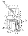
- Fig. 1 and Fig. 2 illustrate the overall configuration of an ink-jet printing apparatus in accordance with a first preferred embodiment of the present invention.
- the ink-jet printing apparatus applies to a serial-scanning system in which a printing head moves in the direction of main-scanning (i.e., the main-scanning direction).
- a main body of the printing apparatus comprises a transport device portion 1 for feeding a printing medium S such as a sheet of paper, a printing device portion 2 for performing a printing movement, an ink-supplying device portion 3 for supplying ink to the printing device portion 2, and a capping device portion 30 (see Fig. 6).
- a transport device portion 1 for feeding a printing medium S such as a sheet of paper
- a printing device portion 2 for performing a printing movement
- an ink-supplying device portion 3 for supplying ink to the printing device portion 2
- a capping device portion 30 see Fig. 6
- the reference numeral 4 denotes a cover.
- the cover 4 is provided on an external side of a main body of the printing apparatus.
- the reference numeral 5 denotes a platform on which a plurality of printing media S is placed.
- the cover 4 has an insertion opening 4a and an ejection opening 4b, so that the printing medium S is inserted into the insertion opening 4a and ejected from the ejection opening 4b.
- a mounting base 8, a feed roller 9, and a guide member 11 are provided in the inside of side walls provided in the cover 4, a mounting base 8, a feed roller 9, and a guide member 11 are provided.
- the mounting base 8 is provided as a means for holding the printing media S.
- the mounting base 8 moves upward and pressed against the feed roller 9 by an extending force of a spring 7.
- the feed roller 9 is a part of feeding means and comes into contact with the topmost printing medium S on the mounting base 8.
- the guide member 10 leads a sheet of the printing medium S separated from a batch
- the reference numeral 12 denotes a photo-sensor for detecting the printing medium S passing through the downstream side of the guide member 11.
- the reference numeral 13 denotes a pair of transport rollers that transports the printing medium S at a constant speed, which is fed from the transport device portion 1.
- the reference numeral 14 denotes a pair of carrying out rollers that carries out the printing medium S on which an image is printed.
- the reference numeral 19 denotes a carriage which is movably supported by guide members 15, 16, so that these guide members 15, 16 are able to guide the movement of the carriage 19 in the main scanning direction indicated by the arrows 28, 35 in Fig. 2.
- the main scanning direction corresponds to the direction along a width of the printing medium S.
- the carriage 19 is able to shift its position along the guide members 15, 16 in the main scanning direction by means of a driving force of a carriage motor 70 transmitted through a belt 18 that runs between pulleys 17 and 17.
- the reference numeral 20 denotes a replaceable reserve ink tank to be mounted on the carriage 19, while 20a denotes a printing head as a means for forming an image on the printing medium S.
- the printing head 20a ejects ink supplied from the reserve ink tank 20.
- the reserve ink tank 20 and the printing head 20a are combined together to form an ink-jet cartridge.
- these components 20, 20a may be individually provided so that they can be detachably connected to each other and individually mounted on the carriage 19.
- the reserve ink tank 20 of the present embodiment is divided into four ink tanks for reserving respective colors of ink, i.e., an ink tank 20Y for yellow colored ink, an ink tank 20M for a magenta colored ink, an ink tank 20C for cyan colored ink, and an ink tank 20B for black colored ink.
- Each of these ink tanks 20Y, 20M, 20C, and 20B has an ink inlet 20b for the admission of ink.
- the ink inlet 20B is formed as a valve member made of a flexible material such as a rubber.
- the reference numeral 48 in Fig. 4 denotes a gas-permeable member provided in a suction opening of each of the ink tanks 20Y, 2M, 20C, and 20B.
- the gas-permeable member 48 is provided as a means of separating air and liquid, which permeates gas but not ink.
- the gas-permeable member 48 may be of a thin-sheet type and made of a tetrafluoride ethylene resin or other porous resin materials. As shown in Fig. 6 and Fig.
- each of passages for exhausting air in the ink tanks 20Y, 20M, 20C, and 20B communicates with the gas-permeable member 48 and an air ventilating path 49 and then communicates with a general suction hole 53 through common air ventilating paths 50, 51, and 52.
- Air in the ink tanks 20Y, 20M, 20C, and 20B can be sucked out of a cap member 54 closely adjacent to a surface 53a on which the general suction hole 53 is formed.
- the suction of air can be performed by a suction pump 31 through a ventilation tube 57.
- the printing head 20a consists of a plurality of head parts. These parts are independent one another in every ink and comprises a plurality of ink eject nozzles 44 and their own liquid chambers 43 communicating with channels 41 of the respective ink tanks 20Y, 20M, 20C, and 20B. Each of the nozzles 44 forms a communicating passage that communicates with an ink eject port. In addition, each of the nozzles 44 has a means for generating an energy to be used for ejecting ink from the ink eject port.
- the reference numeral 21 denotes a means for supplying ink, which communicates with a supplementary ink tank 22 through the tube 21a.
- This ink-supplying means 21 replenishes ink of the supplementary ink tank 22 into the reserve ink tank 20 by tightly connecting to the ink inlet 20b of the reserve ink tank 20.
- the supplementary ink tank 22 of this embodiment is divided into four ink tanks for reserving respective colors of ink, i.e., an ink tank 22Y for yellow colored ink, an ink tank 22M for a magenta colored ink, an ink tank 22C for cyan colored ink, and an ink tank 22B for black colored ink.
- Each ink tank 22Y, 22M, 22C, and 22B are connected to their respective ink-supplying means 21Y, 21M, 21C, 21B which cope with every color of ink through the associated inner tube 21a.
- the ink-supplying means 21 is mounted on a migration board 27.
- the migration board 27 is guided by a guide member 25, 26 so as to be able to move in the left-right direction of Fig. 2. If the carriage 19 moves in the direction of the arrow 28, and the side surface 20B-1 of the reserve ink tank 20B runs into an arm portion of the migration board 27, the migration board 27 moves together with the carriage 19 in the direction of the arrow 28 against the force of a spring 29.
- the carriage 19 turns around the guide member 16 as an axis on in the direction of the arrow 37 by moving the carriage 19 in the direction of the arrow 28.
- connection between the ink-supplying means 21 and the ink inlet 20b of the reserve ink tank 20 is made. That is, as shown in Fig. 3, a pair of guide rollers 19b is mounted on the carriage 19 for supporting the carriage 19 on the guide member 15. If the carriage 19 moves in the direction of the arrow 28, the side surface 20B-1 of the reserve ink tank 20B runs against the arm portion 27a of the migration board 27. Consequently, the migration board 27 begins to move together with the carriage 19 in the direction of the arrow 28.
- a pair of the guide rollers 19b moves from a tilted portion 15a of the guide member 15 to a horizontal portion 15b thereof. Accordingly, as shown in Fig. 5, the carriage 19 turns around an axis of the guide member 16 in the direction of the arrow 37, resulting in the connection between the ink-supplying means 21 and the ink inlet 20b of the reserve ink tank 20.
- the ink-supplying means 21 comprises a needle 21c having a hollow body with a closed tip end.
- the closed tip of the needle 21c has a pore 21b passing through a circumferential surface thereof in the radial direction (the left-right direction of Fig. 5).
- a piston-shaped bung member 21e is co-axially provided on the outer circumference of the needle 21c and is able to move up or down along a central axis of the needle 21c.
- the bug member 21e is made of a flexible material such as rubber and spring-loaded in a downward direction by a spring 21d.
- the pore 21b of the needle 21c is covered by a bung member 21e as shown in Fig. 4. In this case, therefore, there is no leakage of ink from the needle 21c at this time.
- the ink inlet 20b of the ink tank 20 formed by a flexible valve member such as rubber is being closed by the stability of the valve member to restore its original state.
- a capping device portion 30 makes good contact with the printing head 20a and sucks out foreign matter, such as air and thickened ink, which is the cause of the eject defect of the ink.
- the reference numeral 38a is a cap member which covers the surface on which ink eject ports of the printing head are formed (the ink eject port-formed surface).
- the reference numeral 54 is a cap member that makes good contact with the surface 53a on which a general suction port 53 is formed.
- the cap members 38a, 54 are held by a frame body 45, while the frame body 45 is supported by four link arm members 46 so as to allow the up-and-down movements of the frame body 45.
- the reference numeral 47 denotes a spring that pushes the frame body 45 upward.
- the cap members 30a, 54 are connected to ducts 30b, 55, respectively.
- the ducts 30b, 55 are also connected to a change-over mechanism 56 for changing the pump suction ways.
- the projection part 45a located on the migration tracking of the bank part 19a held in the predetermined position of the carriage 19 is held at one end of the frame body 45.
- a bank part 19a hits the projection part 45a at the position of moving the carriage 19, as shown in Fig. 3, the frame body 45 is pushed down against the force of the spring 47.
- the frame body 45 is raised by the spring 47.
- the cap member 38a makes good contact with the surface 53a on which the ink eject ports are formed and also the cap member 54 makes good contact with the surface 53a on which the general suction port 53 is formed.
- the change-over mechanism 56 to be connected with the ducts 30b, 55 has a rotary valve 59 made of rubber as shown in Fig. 6.
- the rotary valve 59 connects the ducts 30b, 55 to the pump suction port 31a of the suction pump 31 through a passage 59a in a selective manner in response to the positions every time the rotary valve 59 is rotated at 90 degrees.
- the rotary valve 59 is fixed on a rotational shaft 56a on which a saw-tooth gear 56b is co-axially placed.
- a proximal end of an arm member 56c is supported by the rotational shaft 56a so as to be able to rotate about the shaft 56a while a ratchet teeth 56d is pivoted on the other end thereof.
- the ratchet teeth 56d engages with the saw-teeth gear 56b in one direction only.
- the reference numeral 56e denotes a spring that pulls the arm member 56c in a clockwise direction in Fig. 3.
- Two location indication members 56f are provided and staggered 180 degrees apart on the saw-tooth gear 56b.
- the reference numerals 57, 58 are location sensors provided in place 90 degrees apart to detect the position of the location indication members 56f.
- Each of the location sensors 57, 58 may be a micro-switch, a photo-sensor, or the like.
- the tip of the arm member 56c is coupled to a pore portion 34b of a selector lever 34 (see Fig. 2) through a coupling shaft 36.
- An end of the selector lever 34 is pivoted around an axial shaft 34a. If the carriage 19 touches the tip of the selector lever 34 by moving the carriage 19 in the direction of the arrow 35, and the carriage 19 further shifts its position in the same direction, the selector lever 34 turns around the axial shaft 34a in the direction of the arrow 35 to the position indicated by a broken line. Synchronizing with the turn of the selector lever 34 in the direction of the arrow 35, the arm member 56c (see Fig. 3) turns 90 degrees in a counterclockwise direction in Fig. 3 against the force of the spring 56e.
- the ratchet teeth 56d engages with the saw-tooth gear 56d, so that the saw-tooth gear 56d turns 90 degrees in a clockwise direction with the rotational shaft 56a and rotary value 59.
- the selector lever 34 and the arm member 46c are turned in the clockwise direction for returning to their original positions by the force of the spring 56e.
- the ratchet teeth 56d does not engage with the saw-tooth gear 56d, so that the saw-tooth gear 56d does not rotate.
- FIG. 6 illustrates the state of switching between the pump suction ways when the location sensor 57 detects the location indication member 56f.
- the general suction port 53 communicates with the pump 31 through the cap member 54, the duct 55, the passage 59a, the pump suction port 31a.
- Fig. 8 illustrates the state of switching between the pump suction ways when the location sensor 58 detects the location indication member 56f.
- a control means 25 (see Fig. 1) to be described later confirms the states of switching the pump suction ways on the basis of detection signals from the location sensors 57, 58. If the state of switching between the pump suction ways is not appropriate to the operation to be down, the control means 25 allows the movement of the carriage 19 in the direction of the arrow 35 and the turn of the selector lever 34 in the direction of the allow 34. Consequently, the switching between the pump suction ways is down so as to be fit to the desired operation.
- the reference numeral 24 denotes an electric substrate arranged in the inside of the cover 4 having a plurality of switch buttons 23 that project upward through the holes formed on the cover 4.
- the reference numeral 25 denotes a control means that comprises a microcomputer, a memory, and so on mounted on a control electric substrate arranged in the inside of the cover 4.
- the control means 25 controls the functions of the printing apparatus in communication with a host computer.
- the suction pump 31 comprises a piston member 31e which is co-axially provided in a cylinder member 31c having a suction inlet 31a and an outlet 31b.
- a seal member 31d is placed between the piston member 31e and the cylinder member 31c.
- the piston member 31e is able to perform a reciprocating motion in the cylinder member 31c.
- a pore 31f provided in the piston member 31e has a reed valve 31g that restricts the flow of ink only to the one-way (i.e., the left side of Fig. 6).
- the reference numeral 31h is a piston shaft that actuates the piston member 31e
- 31i denotes a spring member that pushes the piston member 31e to the right side of Fig. 6.
- Ink and air absorbed by such a suction pump 31 pass from the outlet 31b to the discharge pipe 31j. Then, they are discharged toward the sponge-like ink absorber 33a in a liquid waste container 33.
- the piston shaft 31h performs a reciprocating motion in the left-right direction of Fig. 6 in response to the turn of a cam part 32a of a cam gear 32 to be described later.
- the piston member 31e performs a reciprocating motion in the left-right direction in synchronization with the movement of the piston shaft 31h, so that air and ink absorbed from the suction port 31a are discharged to the outlet 31b.
- a gear 56 is installed on the shaft 13a of the transport roller 13 through a one-way clutch 13b.
- the gear 56 can be rotated by a drive motor 60. If a drive shaft of the drive motor 60 is rotated counterclockwise, the shaft 13a of the transport roller 13 is rotated. If the drive shaft of the drive motor 60 is rotated clockwise, the cam gear 32 is rotated.
- the cam gear 32 has a cam part 32a that touches the piston shaft 31h by the force of the spring 31i. The location where the cam part 32a touches the piston shaft 31h changes in response to the turning of the cam gear 32. As a result, the piston shaft 31h is moved right and left as a reciprocating motion.
- the piston member 31e is moved right and left as a reciprocating motion in conjunction with the piston shaft 31h. If the piston member 31e moves toward the light side, the valve 31g is closed by a pressure generated in a pressure chamber 31k on the left side to exhaust ink and air in the pressure chamber 31k from the outlet 31b to the liquid waste container 33. Moreover, the volume of a pressure chamber 31m on the right side is increased, and simultaneously negative pressure is generated in the pressure chamber 31m. The negative pressure allows the suction of ink and air from the suction port 31a. On the other hand, ink and air in the pressure chamber 31m on the right side are moved to the pressure chamber 31k on the left side by passing through the pore 31f when the piston member 31e is moved to the right side.
- the image data to be transmitted to a printing device portion 2 from a host computer is expanded on the occasion of the printing movement.
- the control means 25 controls the movement of the carriage 19 in the main-scanning direction, the transport of the printing medium S by a pair of the transport rollers 13, 14 in the sub-scanning direction, and the actuation of the printing head 20a.
- the printing head 20a prints a color image on the printing medium S by ejecting ink droplets of each color using nozzles 44 being controlled on the basis of the process of gradating an image (the procedures of overlaying color dots).
- the photosensor 12 detects the end of the printing medium S. After performing the printing movement on the end of the printing medium S, a pair of rollers 14 rotates to discharge the printing medium S on which an image is printed from the outlet 4b.
- control means 25 When the power of the printing apparatus turns on, or the printing movement is not operated during more than predetermined time after the power of the printing apparatus turns on, the control means 25 allows an automatically start of the recovery action to get rid of thickened ink or air bubbles formed in the nozzles of the printing head 20a. If the printed image has some color faint, inconsistencies in density, or the like, the control means 25 starts the recovery action in the same way by pushing predetermined control buttons (see Fig. 1).
- the control device 25 confirms whether the location sensor 58 in the mechanism 56 that switches between suction ways is in the state of detecting the location indication member 56f. If the location indication member 56f is detected by the location sensor 57, the carriage 19 is moved in the direction of the arrow 35 (the left side direction) so that the selector lever 34 turns in the direction of the arrow 35. Consequently, it becomes the condition of detecting the location indication member 56f by the location sensor 58 (i.e., the condition of switching between the suction ways as shown in Fig. 8). The control means 25 confirms that it is in the state that the location sensor 58 detects the location indication member 56f. After that, as shown in Fig. 5, Fig. 7, and Fig.
- the carriage 19 is moved so that the cap member 38a touches the printing head 20a and the cap member 54 touches the general suction port 53.
- the control means 25 rotates the cam gear 32 by running a motor 60 (see Fig. 4) in the clockwise direction through the gear 59. Consequently, the suction pump 31 absorbs thickened ink and air in the nozzles 44 of the printing head 20a and discharges them into the liquid waste container 33.
- the piston member 31e of the suction pump 31 does the actuation of one cycle of the absorption and the discharge by a turn of the cam gear 32.
- the number of rotate of the cam gear 32 depends on the magnitude of the essential negative pressure for the recovery of the eject defect of the printing head 20a.
- the number of ink droplets ejected by the printing head 20a is counted with the control means 25 in each ink color. If at least one of the count value of each ink color meets a predetermined number, when the printing movement to the printing medium S is completed, and so the printed printing medium S is ejected from the printing apparatus, the control means 25 starts to actuate the ink-supply to the reserve ink tank 20 from the supplementary ink tank 22 (see Fig. 1).
- the control means 25 confirms whether it is in the condition that the location sensor 57 in the suction-way switching mechanism 56 detects the location indication member 56f.
- the selector lever 34 is turned in the direction of the arrow 35 by moving the carriage 19 in the direction of the arrow 35 (the left side). Consequently, it becomes the condition that the location sensor 57 detects the location indication member 56f, that is, the condition of switching between the suction ways as shown in Fig. 6.
- the control means 25 confirms that it is in the state that the location sensor 57 detects the location indication member 56f. After that, as shown in Fig. 5, Fig. 6, and Fig.
- the carriage 19 is moved so that the cap member 38a touches the printing head 20a and the cap member 54 touches the general suction port 53.
- the control means 25 rotates the cam gear 32 by running a motor 60 (see Fig. 4) in the clockwise direction through the gear 59. Consequently, the suction pump 31 absorbs air in the reserve ink tank 20 through the gas-permeable member 48, and ejects them into the liquid waste container 33.
- the inside of the reserve ink tank 20 becomes negative pressure as a result of absorbing air in the reserve ink tank 20 by the suction pump 31.
- the supply means 21 connects the supplementary ink tank 22 (see Fig.1) to the reserve ink tank 20. Therefore, ink in the supplementary ink tank 22 is absorbed into the inside 41 of the reserve ink tank 20 by the negative pressure in the reserve ink tank 20.
- the ink being entered into the inside 41 of the reserve ink tank 20 permeates an ink absorber 41a that consists of a cluster of small cells that communicate with each other.
- a liquid level 41b of the ink rises as the ink permeates the ink absorber 41a.
- the rise rate of the liquid level 41b of the ink is adjusted properly on the basis of rotational frequency of the cam gear 32 as it depends on the suction force of the suction pump 31. If the liquid level 41b of the ink reaches the gas-permeable member 48, the supply of ink is automatically stopped because the gas-permeable member 48 does not permeate a fluidal material such as ink. Ink is supplied from the supplementary ink tanks 22 (22Y, 22M, 22C, 22B) to the respective reserve ink tanks 20 (20Y, 20M, 20C, 20B) at the same time.
- the supply of ink to the reserve ink tanks 20 (20Y, 20M, 20C, 20B) is automatically stopped one after another in order of reaching the liquid level 41b of the ink to the gas-permeable member 48. If the supply of ink is completed, the control means 25 resets the counter of ejected ink droplets to zero for each of ink color.
- air in all of the reserve ink tanks 20 (20Y, 20M, 20C, 20B) can be absorbed through the use of a single cap member 54 and simultaneously refilled. Therefore, there is no need to provide a suction port 53b and a cap member 54 for each of the reserve ink tanks 22 (22Y, 22M, 22C, 22B), so that both the size and weight reductions of the structural components of the capping device portion 30 on the side of the carriage 19 are achieved.
- the reliability of a device area that makes the reserve ink tanks 20 (20Y, 20M, 20C, 20B) negative pressure can be secured.
- the reserve ink tank 20 is inclined at an angle as shown in Fig. 7 during the step of supplying ink, so that an area 41c where ink is not absorbed is found in an ink absorber 41a in the inside 41 of the tank 20. After the supply of ink, the reserve ink tank 20 gets back to a horizontal position as shown in Fig. 4. In this case, ink permeates through the area 41c of the ink absorber 41a. Thus, the liquid level 41b of ink over the surface of the gas-permeable member 48 as shown in Fig. 7 moves downward and leaves from the surface of a gas-permeable member 48 as shown in Fig. 4.
- the gas-permeable member 48 permeates ink as a result of its decreased function when it is being touched ink, as the characteristics of the gas-permeable member 48, it is effective to leave ink from the surface of the gas-permeable member 48 all the times except the time of supplying ink.
- the suction pump 31 of the present embodiment combines the function as an absorbing means to absorb ink for the recovery operation to the printing head 20a with another function as an absorbing means to absorb air in the reserve ink tank 20 for the supply of ink. Therefore, the present embodiment is able to provide a substantially simplified and low-cost printing apparatus, compared with the one having a plurality of suction pumps for those functions. Furthermore, negative pressure to be applied on the inside of the reserve ink tank 20 during the period of supplying ink is adjusted to a predetermined level in order to prevent a backward current of ink from the nozzles 44 to the reserve ink tank 20 when the ink eject ports are being opened. During the period of supplying ink, the ink eject ports may be sealed with the cap member.
- Figs. 9 to 17 illustrate an second preferred embodiment of the present invention.
- an ink inlet 20b and a suction port 53b are formed on each of the reserve ink tanks 20Y, 20M, 20C, and 20B of Fig. 10.
- Each suction port 53b has the same gas-permeable member (not shown) as that of the first embodiment described above.
- the reference numeral 201 denotes a supply joint for each type of ink.
- the supply joint 201 is configured to make a connection to each ink inlet 20b, and connected to the same ink supply system as that of first embodiment described above.
- the reference numeral 202 denotes a suction joint configured to make connection to each suction port 53b as shown in Fig. 11. All suction joints 202 are gathered into the suction passage 53c and then connected to the same ink suction system as that of the first embodiment described above.
- the letter “L” in Fig. 13 represents a detection reference level for detecting the level 41b of ink.
- a means for detecting the level 41b of ink may be an electric level sensor, an optical level sensor, or the like.
- the electric level sensor detect the level 41b due to the existence of ink between electrodes placed in the reserve ink tank 20.
- the remaining amount of ink in the reserve ink tank 20 may be estimated by obtaining the amount of ink consumed on the basis of the number of ink-eject from the printing head 20a.
- the remaining amount of ink may be detected in each of the reserve ink tanks 20Y, 20M, 20C, and 20K.
- the suction passage 53c has a stopper 203 as a means for closing or opening the suction passage 53c.
- a stopper portion 203A is formed on an outer peripheral surface of the stopper 203 as shown in Fig. 12A and Fig. 12B. If the stopper 203 rotates about its central axis "O" so that the stopper portion 203A faces the suction passage 53c, as shown in Fig. 13, the stopper portion 203A presses and closes the suction passage 53c. If the stopper 203 rotates about its central axis "O" so that the stopper portion 203A is detached from the suction passage 53c, the suction passage 53c returns to its original open state.
- the suction passage 53c is opened at first. Then, negative pressure is caused in each ink tank 20 from the suction port 53b through the gas-permeable member as in the case of the embodiment described above.
- the negative pressure allows the supply of ink through the ink inlet 20b.
- the process including these steps is so-called "the action of supplying ink”.
- the action of supplying ink allows the concurrent supply of ink to the reserve ink tanks 20Y, 20M, 20C, and 20K.
- the stopper 203 closes the suction passage 53c except when the action of supplying ink is currently progress.
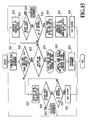
- Fig. 17 is a timing chart for illustrating a series of actuation of the printing apparatus.
- the printing apparatus receives printing data "D" corresponding to one page of the printing medium.
- the printing apparatus repeats the steps of: performing the printing movement for printing one line of the image by moving the printing head 20a in the main-scanning direction after the action of providing the printing medium; and feeding the printing medium for one line of the image.
- the printing medium is discharged from the printing apparatus and then the next printing medium is provided to perform the next printing movement.
- the action of capping shown in Fig. 17 is for the printing head 20a.
- a capping means is detached from the printing head 20a, bringing about its "OPEN” state (hereinafter, also referred to as a "cap-open” state), and then the capping means is attached to the printing head 20b after performing a series of steps in the printing movement, bringing about its "CLOSE” state (hereinafter, also referred to as a "cap-close” state).
- the recovery action is performed prior to the cap-close state, which makes the printing head 20a eject a predetermined amount of ink without contributing to any image formation.
- the recovery movement may include the action of discharging ink from nozzles 44 of the printing head 20a under suction, the action of primary eject of ink from the printing head 20a, or the like.
- the supply of ink shown in Fig. 17 is the action of supplying ink described later, which can be performed every time after printing an image on one page of the printing medium.
- Fig. 15 is a flow chart for illustrating the action of supplying ink.
- the printing apparatus After the printing movement by one page of the printing apparatus, the printing apparatus detects the remaining amount of ink in each of the reserve ink tanks 20Y, 20M, 20C, and 20K. Subsequently, it judges whether the remaining amount of ink is decreased to a predetermined level by which it becomes necessary to supply the required amount of ink on the basis of the results of such a detection (steps S21, S22). In this embodiment, such a judgement is based on a rule that the need for supplying ink arises when the level 41b of ink is lowered than a predetermined level "L".
- the printing apparatus is kept in the cap-open state (step S23) or performs the printing movement when it receives printing data "D" (step 25). If the printing data "D" is not received even if fixed time has elapsed, it is switched to the cap-close state (in this embodiment, after lapse of 30 seconds) to complete to sequence.
- step S28 If the supply of ink is required, it is judged whether there is a need for printing the next page (step S28).
- the ink tank having the minimum remaining amount of ink is judged from the reserve ink tanks 20Y, 20M, 20C, and 20K at the time of printing the next page (i.e., at the state of ink-supply "SA" in Fig. 17).
- the reserve ink tank 20Y is judged as the one having the minimum remaining amount of ink.
- the ink tank having the minimum remaining amount of ink receives the supply of ink until it is filled up to a predetermined target remaining amount of ink enough to perform the printing movement (step S30).
- the target remaining amount of ink may be defined as the amount of ink that corresponds to the predetermined level "L" of ink. Moreover, the target remaining amount of ink may be also defined as the minimum amount of ink to be required for printing an image on the next one page.
- the ink tanks may have their respective target remaining amounts of ink.
- the supply of ink to the ink tank filled up with ink is automatically stopped by means of the gas-permeable member during the action of supplying ink. In the case of shown in Fig. 14, the actions of supplying ink to both the reserve ink tanks 20M, 20B are automatically stopped. Following such an action of supplying ink, the next printing movement for one page is performed (step S31).
- a sequence of the cap-open shown in Fig. 16B is executed. That is, the printing head 20a ejects ink which is not responsible for any image formation (primary eject) every five seconds until a predetermined time interval is expired (in this embodiment, 30 seconds) (steps S61, S62, S63). After a lapse of 30 seconds, the printing head 20a is subjected to the step of wiping (step 64) and the step of primary eject (step S65), followed by the step of cap-close (step S66) to complete the sequence.
- the printing head 20b waits a predetermined time interval (in this embodiment, 30 seconds) for the input of the printing data "D". If the printing head receives the printing data "D" within the predetermined time interval, the printing movement is performed (step S34). If it does not receive the printing data "D" within the predetermined time interval, each of the reserve ink tanks 20Y, 20M, 20C, and 20K is filled with ink by the action of supplying ink (step S36). The supply of ink to each of the reserve ink tanks 20Y, 20M, 20C, and 20K is automatically stopped in order of being filled up with ink. Following the step of supplying ink to fill up the respective reserve ink tanks 20Y, 20M, 20C, and 20K, a sequence for detecting the remaining amount of ink in each of them described later is performed and then completed after the cap-close (step S38).
- a predetermined time interval in this embodiment, 30 seconds
- the reserve ink tanks 20Y, 20M, 20C, and 20K are filled up with ink respectively during the period after the printing movement without imposing a severe time limit.
- the printing movement can be started at one because the reserve ink tanks 20Y, 20M, 20C, and 20K are being filled up with ink at the time of rebooting the printing apparatus.
- the adhesion of ink in the reserve ink tank 20 can be prevented by keeping the reserve ink tank 20 in a state of being filled up with ink.
- Fig. 16A is a flow chart for illustrating a sequence of detecting the remaining amount of ink in the reserve ink tank 20.
- step S40 the sequence is switched on (step S40) and then starts to judge whether the charge of ink into the respective reserve ink tanks 20Y, 20M, 20C, and 20K is completed (step S41). If the charge of ink is completed, the sequence is terminated. If the charge of ink is not completed, the same action of aspirating ink as that of the step S36 is performed (step S42). Subsequently, it is judged again that whether the charge of ink is completed (step S41). If the charge of ink is completed, the sequence is terminated. If it is not completed, it is judged that the main-tank (refill ink tank) to be used for supplying ink to the reserve ink tank 20 is empty and then an error is represented on a display means (not shown) (step S44).
- the reserve ink tank 20 may be always connected to the ink-supplying system and the air-suction system.
- Figs. 18 to Fig. 22 are explanatory views of a third preferred embodiment of the present invention.
- each of the reserve ink tanks 20Y, 20M, 20C, and 20B has its own ink inlet 20b and suction port 53b as shown in Fig. 18.
- the reference numeral 201 denotes a supply joint to be connected to the ink inlet 20b of the ink tank. Every supply joint 201 corresponds to its own ink tank with specific ink color.
- the supply joint is connected to an ink-supplying system just as in the case of the embodiment described above.
- the reference numeral 202 denotes a suction joint to be connected to each of the suction ports 53b.
- the suction joint 202 is connected to a suction system by an individual suction passage 53d just as in the case of the embodiment described above.
- the letter “L” in Fig. 18 represents a detection standard level of the height (level) 41b of ink in the reserve ink tank 20.
- a means for detecting the level 41b of ink may be an electric level sensor or an optical level sensor.
- the electric level sensor detect the level 41b of ink due to the existence of ink between electrodes placed in the reserve ink tank 20.
- the remaining amount of ink in the reserve ink tank 20 may be estimated by counting the number of ejecting ink. The remaining amount of ink is estimated for each of the reserve ink tanks 20Y, 20M, 20C, and 20K.
- Each of the suction passages 53d is provided with a stopper 300 as a means for opening or closing the suction passage 53d.
- a plurality of stopper portions 300A are formed on an outer peripheral surface of the stopper 300 as shown in Fig. 19A and Fig. 19B.
- the stopper portions 300A are grouped into four different stopper groups in the direction of the radius of the stopper 300, i.e., a first stopper group 301, a second stopper group 302, a third stopper group 303, and a fourth stopper group 304, which correspond to their respective suction passages 53d of the reserve ink tanks 20Y, 20M, 20C, and 20K, respectively.
- Each of the suction passages 53d of the respective reserve ink tanks 20Y, 20M, 20C, and 20K is selectively opened as the stopper 300 rotates about its central axis "O".
- the suction passages 53d of the reserve ink tanks 20M, 20C, and 20K are closed, because stopper groups 302, 303 and 304 faces and presses those passages 53d, while the suction passage 53d of the reserve tank 20Y is opened because stopper group 301 detaches from the passage 53d.
- only the suction passage 53d of the reserve ink tank 20C is opened.
- one of the suction passages 53d is opened at first. Then, negative pressure is caused in each ink tank 20 from the suction port 53b as in the case of the embodiment described above.
- the negative pressure allows the supply of ink through the ink inlet 20b.
- the process including these steps is so-called "the action of supplying ink”.
- the action of supplying ink allows the supply of ink to the reserve ink tanks 20Y, 20M, 20C, and 20K in a selective manner.
- the stopper 203 may close all of the suction passages 53d except when the action of supplying ink is currently progress.
- Fig. 22 is a timing chart for illustrating a series of the action of supplying ink. The same steps as those of the second embodiment are not described in the following description and the same structural components have the same reference numerals just as in the case of the second embodiment.
- steps S51, S52, and S54 are performed in stead of the steps S29 and S30 in the second embodiment. That is, if there is a need for supplying ink and printing the next page of the printing medium, the process proceeds from the step S28 to the step S51.
- the step 51 it is judged which the reserve ink tank 20 requires the supply of ink. If the criterion of the judgement is the level "L" of ink and the level of ink in each of the reserve ink tanks 20Y, 20M, 20C, and 20K is in the state shown in Fig. 18, it is determined that the reserve ink tanks 20Y, 20C require the supply of ink.
- the suction passage 53d of one of the reserve ink tanks that require the supply of ink is opened for refilling it, so that it receives ink by the action of ink supply (step S52).
- the reserve ink tank 20 is refilled with ink by such a step of supplying ink so that the remaining amount of ink in the ink tank reaches a predetermined level (i.e., a target remaining amount of the ink).
- the target remaining amount of ink may be defined as the amount of ink that corresponds to the predetermined level "L" of ink.
- the target remaining amount of ink may be also defined as the minimum amount of ink to be required for printing an image on the next one page.
- step S31 the process returns to the step S51 if the reserve ink tank that requires the supply of ink remains about the same. Then, the suction passage 53d of such an ink tank is opened by the stopper 300, followed by the supply of ink in an analogous fashion (step S52). If there is no reserve ink tank that requires the supply of ink, the printing movement for the next one page is performed (step S31).
- the reserve ink tanks 20Y, 20C require the supply of ink.
- the remaining amount of ink in the reserve ink tank 20Y is less than that of the reserve ink tank 20Y, so that the supply of ink is performed on the reserve ink tank 20Y at first as shown in Fig. 20, followed by the supply of ink to the reserve ink tank 20C as shown in Fig. 21.
- At least two suction passages 53d may be concurrently opened for supplying ink to a plurality of the reserve ink tanks at a time.
- the supply of ink can be automatically stopped by installing a gas-permeable member (not shown) on each suction port 53b just as in the case of the above embodiments.
- an ink detector is installed in the suction port 53b of the reserve ink tank (sub ink tank) 20 having the gas-permeable member 48, so that the status of ink-supply can be confirmed all the time. As a result it is a possible that cope with the status of ink-supply. If ink is not arrived at the gas-permeable member 48 within a fixed time period, it is determined that there is no ink in the supplementary ink tank (i.e., the main ink tank) to refill ink to the reserve ink tank 20 and such a status is represented by a display means. Alternatively, the status of ink supply may be displayed after verifying that ink is filled up to the level of the gas-permeable member 48.
- Figs. 23 to 27 are explanatory views that illustrate the configuration of the ink detector.
- Fig. 23 is a schematic structural view of a reserve ink tank 20 having a gas-permeable member 48 in a suction port 53b.
- the reference numeral 20b denotes a supply port (an ink inlet) to be connected to a supplementary ink tank (a main ink tank) for supplying ink to the reserve ink tank 20.
- the reference numeral 20e denotes a supply port for supplying ink to an ink-jet printing head.
- the reference numeral 41a denotes an ink absorber for retaining ink by absorption.
- an ink detector comprises a pair of electrodes 701 being placed near the gas-permeable member 48.
- the ink detector detects the presence or absence of ink between the electrodes 701.
- an ink detector comprises a pair of electrodes 701 being curved around the peripheral wall of the suction port 53b.
- an optical detecting means that comprises an prism 702 in the space near the gas-permeable member 48 so that the presence and absence of ink in such a space is detected.
- a prism 702 is located in the space between the ink absorber 41a and the gas-permeable member 48.
- the ink tank having one of the above ink detecting means may be configured so that it is detachably connected to an ink-supplying system and an air suction system as required or it is normally connected to these systems.
- the ink absorber 41a is not an absolute necessity for the present embodiment.
- the characteristics and shapes of a gas-permeable member 48 of each reserve ink tanks 20 (20Y, 20M, 20C, and 20B) may be modified with reference to the characteristics of ink, the amount of ink to be stored in such an ink tank, or the like.
- the gas-permeable member 48 may be a porous body having its own characteristics and shape based on a desired level of negative pressure to be caused in the reserve ink tank 20 in accordance with the type of ink to be stored and the ink capacity of the reserve ink tank 20 in which the gas-permeable member 48 is installed.
- the gas-permeable member 48 may be a porous body having its own pore diameter and thickness.
- an occupying area of the gas-permeable member 48 in a ventilating path 49 in may be formed so as to have its own dimension, while the gas-permeable member 48 may be adopted in size or shaped in accordance with the occupying area of the gas-permeable member 48 in the ventilating path 49.
- the occupying area of the gas-permeable member 48 may be a variable one having a lid member that covers the surface of the gas-permeable member 48 in an adjustable or variable manner.
- the supply rate of ink to each of the reserve ink tanks 20 (20Y, 20M, 20C, and 20C) can be controlled by adjusting a level of negative pressure in the reserve ink tank 20. If the reserve ink tank 20 stores the ink having a large flow resistance or the ink capacity of the ink tank 20 is comparatively large, an appropriate gas-permeable member 48 is selected to adjust negative pressure in the reserve ink tank 20 to a comparatively large level for efficiently supplying ink to one or more reserve ink tanks 20.
- the characteristics of the gas-permeable member 48 can be optically adjusted using parameters such as a pore size and a thickness of the gas-permeable member 48 or an opening area of the ventilating path 49.
- the materiality (e.g., the gas permeability) of the gas-permeable member 48 itself can be made different.
- the gas-permeable member may be of having the function of separating gas and liquid, so that various kinds of materials may be used in accordance with the types of ink or usage patterns.
- the gas-permeable member may be a gas-permeable film made of a tetrafluoride ethylene resin or other porous resin materials.
- a gas-permeable film made of a tetrafluoride ethylene resin or other porous resin materials.
- another porous material made of a natural or synthesis material such as knitted fabric, woven fabric, non-woven fabric, net, felt, porcelain, unglazed pottery, earthenware, or ceramic.
- the gas-permeable member may be a mechanical valve that is closed when gas comes and opened when the flow of liquid comes.
- the ink tank of the present invention is not limited to the one that moves together with the printing head in the serial-scan type printing apparatus. It is also possible to fix the ink tank in place while the printing head moves.
- the present invention may be also configured that the main tank for supplying to the ink tank is always connected to the ink tank through the tube.
- the ink tank is not limited to the one that moves together with the printing head. It is also possible to fix the ink tank in place.
- the present invention may adopt any of various modes of image formation, for example a mode of printing an image on one line basis or one page basis. It is essential only that the change in the way of ink supply eventually increases the printing rate.
Landscapes
- Ink Jet (AREA)
Applications Claiming Priority (2)
| Application Number | Priority Date | Filing Date | Title |
|---|---|---|---|
| JP11153061A JP2000334976A (ja) | 1999-05-31 | 1999-05-31 | インクジェット記録装置、インク供給装置、およびインク供給方法 |
| JP15306199 | 1999-05-31 |
Publications (3)
| Publication Number | Publication Date |
|---|---|
| EP1057645A2 true EP1057645A2 (de) | 2000-12-06 |
| EP1057645A3 EP1057645A3 (de) | 2002-08-07 |
| EP1057645B1 EP1057645B1 (de) | 2007-10-17 |
Family
ID=15554139
Family Applications (1)
| Application Number | Title | Priority Date | Filing Date |
|---|---|---|---|
| EP00304623A Expired - Lifetime EP1057645B1 (de) | 1999-05-31 | 2000-05-31 | Tintenstrahldruckvorrichtung und Tintenversorgungsverfahren |
Country Status (4)
| Country | Link |
|---|---|
| US (1) | US6447084B1 (de) |
| EP (1) | EP1057645B1 (de) |
| JP (1) | JP2000334976A (de) |
| DE (1) | DE60036751T2 (de) |
Families Citing this family (32)
| Publication number | Priority date | Publication date | Assignee | Title |
|---|---|---|---|---|
| US6629758B2 (en) * | 2000-04-19 | 2003-10-07 | Canon Kabushiki Kaisha | Joint device, ink jet recording apparatus having the same, and ink supplying device and method |
| JP3787520B2 (ja) * | 2000-12-28 | 2006-06-21 | キヤノン株式会社 | 構造体の製造方法およびその製造装置 |
| JP3787522B2 (ja) * | 2001-12-28 | 2006-06-21 | キヤノン株式会社 | 構造体、液体タンク、インクジェット記録装置の製造方法およびインクジェット記録装置 |
| US7172260B2 (en) * | 2002-03-04 | 2007-02-06 | Seiko Epson Corporation | Liquid spraying method, liquid spraying system, and liquid spraying execute program |
| US8454135B2 (en) | 2003-02-04 | 2013-06-04 | Brother Kogyo Kabushiki Kaisha | Air bubble removal in an ink jet printer |
| ATE358590T1 (de) * | 2003-02-04 | 2007-04-15 | Brother Ind Ltd | Luftblasenentfernung bei einem tintenstrahldrucker |
| US7029083B2 (en) * | 2003-11-26 | 2006-04-18 | Fuji Xerox Co., Ltd. | Systems and methods for controllably refilling a fluid quantity sensing fluid ejection head |
| US6981754B2 (en) * | 2003-12-30 | 2006-01-03 | Xerox Corporation | Ink delivery and printing method for phasing printing systems |
| US7072217B2 (en) * | 2004-02-24 | 2006-07-04 | Micron Technology, Inc. | Multi-state memory cell with asymmetric charge trapping |
| EP1595704B1 (de) * | 2004-05-12 | 2012-01-11 | Brother Kogyo Kabushiki Kaisha | Farbstrahldrucker |
| JP2006035850A (ja) * | 2004-06-24 | 2006-02-09 | Canon Inc | 液体供給方法 |
| JP4522245B2 (ja) * | 2004-12-09 | 2010-08-11 | キヤノン株式会社 | 液体収容容器及びインクジェット記録装置 |
| JP4434032B2 (ja) | 2005-02-16 | 2010-03-17 | セイコーエプソン株式会社 | 液滴吐出装置の制御方法、液滴吐出装置、電気光学装置の製造方法 |
| JP2008087226A (ja) * | 2006-09-29 | 2008-04-17 | Seiko Epson Corp | 印刷装置、印刷方法及びそのプログラム |
| JP4826471B2 (ja) * | 2006-12-29 | 2011-11-30 | ブラザー工業株式会社 | 記録装置 |
| JP5483910B2 (ja) * | 2009-03-10 | 2014-05-07 | キヤノン株式会社 | インクジェット記録装置 |
| JP5202396B2 (ja) * | 2009-03-10 | 2013-06-05 | キヤノン株式会社 | インクジェット記録装置およびインク供給方法 |
| JP4645752B2 (ja) * | 2009-06-12 | 2011-03-09 | セイコーエプソン株式会社 | 液滴吐出装置の制御方法および液滴吐出装置 |
| JP5522509B2 (ja) * | 2009-09-04 | 2014-06-18 | 株式会社リコー | インクジェット記録装置 |
| JP5468956B2 (ja) * | 2010-03-29 | 2014-04-09 | 理想科学工業株式会社 | インクジェットプリンタ |
| JP5671938B2 (ja) * | 2010-10-22 | 2015-02-18 | セイコーエプソン株式会社 | プリンター |
| JP6557978B2 (ja) | 2015-01-21 | 2019-08-14 | ブラザー工業株式会社 | インクジェット記録装置、及びプログラム |
| US9623691B2 (en) * | 2015-01-21 | 2017-04-18 | Brother Kogyo Kabushiki Kaisha | Inkjet recording apparatus with cover and method therefor including inquiry and notification features |
| JP6390444B2 (ja) | 2015-01-21 | 2018-09-19 | ブラザー工業株式会社 | インクジェット記録装置、及びプログラム |
| JP6579800B2 (ja) | 2015-05-25 | 2019-09-25 | キヤノン株式会社 | インクジェット記録装置 |
| JP6308989B2 (ja) | 2015-09-30 | 2018-04-11 | キヤノン株式会社 | 液体収納容器及び液体吐出装置 |
| JP6723729B2 (ja) | 2015-11-17 | 2020-07-15 | キヤノン株式会社 | 液体収容容器および液体収容容器の製造方法 |
| JP6624905B2 (ja) | 2015-11-26 | 2019-12-25 | キヤノン株式会社 | 液体容器および液体残量検出装置 |
| US10391776B2 (en) | 2015-11-30 | 2019-08-27 | Canon Kabushiki Kaisha | Liquid storage container and printing apparatus |
| JP7532055B2 (ja) | 2020-03-24 | 2024-08-13 | キヤノン株式会社 | 液体供給装置 |
| JP7504641B2 (ja) | 2020-03-27 | 2024-06-24 | キヤノン株式会社 | 液体吐出装置 |
| JP7520574B2 (ja) | 2020-05-22 | 2024-07-23 | キヤノン株式会社 | 液体カートリッジおよび液体吐出装置 |
Family Cites Families (13)
| Publication number | Priority date | Publication date | Assignee | Title |
|---|---|---|---|---|
| US4187511A (en) * | 1978-03-20 | 1980-02-05 | Centronics Data Computer Corp. | Method and apparatus for filling the movable reservoir of an inkjet printer |
| JPS59207256A (ja) | 1983-05-11 | 1984-11-24 | Canon Inc | インクジェット記録装置 |
| US4967207A (en) * | 1989-07-26 | 1990-10-30 | Hewlett-Packard Company | Ink jet printer with self-regulating refilling system |
| CA2052243C (en) | 1990-09-27 | 1999-06-01 | Junji Shimoda | Ink jet recording apparatus and ink cartridge usable therewith |
| US5757390A (en) * | 1992-08-12 | 1998-05-26 | Hewlett-Packard Company | Ink volume sensing and replenishing system |
| JPH0732606A (ja) * | 1993-07-26 | 1995-02-03 | Brother Ind Ltd | インクジェットプリンタ |
| JP3122323B2 (ja) | 1995-01-13 | 2001-01-09 | キヤノン株式会社 | インクタンクおよびそれを搭載するインクジェット記録装置 |
| JPH08300681A (ja) | 1995-05-10 | 1996-11-19 | Matsushita Electric Ind Co Ltd | インクジェットプリンタ |
| JPH0929991A (ja) * | 1995-07-21 | 1997-02-04 | Oki Data:Kk | 印字タンク搭載記録装置 |
| JPH10128999A (ja) | 1996-10-30 | 1998-05-19 | Canon Inc | インクジェット装置 |
| JP3380708B2 (ja) | 1997-05-16 | 2003-02-24 | キヤノンアプテックス株式会社 | インクジェット画像形成方法 |
| JP3835496B2 (ja) | 1997-07-04 | 2006-10-18 | リコープリンティングシステムズ株式会社 | インクジェットプリンタのインク補給方式 |
| US6106108A (en) * | 1998-10-30 | 2000-08-22 | Hewlett-Packard Company | Adaptive image-based algorithm for refill-while-printing triggering |
-
1999
- 1999-05-31 JP JP11153061A patent/JP2000334976A/ja active Pending
-
2000
- 2000-05-31 DE DE60036751T patent/DE60036751T2/de not_active Expired - Lifetime
- 2000-05-31 EP EP00304623A patent/EP1057645B1/de not_active Expired - Lifetime
- 2000-05-31 US US09/583,570 patent/US6447084B1/en not_active Expired - Lifetime
Also Published As
| Publication number | Publication date |
|---|---|
| DE60036751T2 (de) | 2008-03-06 |
| US6447084B1 (en) | 2002-09-10 |
| EP1057645B1 (de) | 2007-10-17 |
| EP1057645A3 (de) | 2002-08-07 |
| DE60036751D1 (de) | 2007-11-29 |
| JP2000334976A (ja) | 2000-12-05 |
Similar Documents
| Publication | Publication Date | Title |
|---|---|---|
| EP1057645B1 (de) | Tintenstrahldruckvorrichtung und Tintenversorgungsverfahren | |
| EP1057644B1 (de) | Tintentank und Tintenstrahldruckvorrichtung | |
| EP1147904B1 (de) | Verbindungsvorrichtung, Tintenstrahlaufzeichnungsgerät mit dieser Vorrichtung, und Tintenversorgungsvorrichtung und -verfahren | |
| US4965596A (en) | Ink jet recording apparatus with waste ink distribution paths to plural cartridges | |
| US6561637B2 (en) | Ink jet head having buffer tank in fluid communication with ink circulation pathway | |
| JP3674036B2 (ja) | インクカートリッジおよびこれを用いたインクジェット式記録装置並びに同装置における記録ヘッドのクリーニング制御方法 | |
| KR100314876B1 (ko) | 잉크젯프린터 | |
| KR20010041830A (ko) | 잉크젯 하드카피 장치와 그를 위한 쓰기 엔진, 쓰기 모듈서브시스템, 하드카피 장치, 하드카피 엔진 및 하드카피장치의 작동 방법 | |
| JPH07323576A (ja) | インクジェット式記録装置 | |
| JP3606356B2 (ja) | インクジェット式記録装置および同装置におけるインク供給制御方法 | |
| JP2004188758A (ja) | カラーインクジェットプリンタ装置 | |
| JP2002200774A (ja) | 液体タンクならびにこれに関する液体補給装置およびその方法ならびにヘッドカートリッジ,画像形成装置 | |
| JPH09220816A (ja) | インクジェット記録装置 | |
| JP4882172B2 (ja) | 印字装置 | |
| JP5754621B2 (ja) | 画像形成装置 | |
| JP2004058663A (ja) | インクジェット記録装置およびその操作方法 | |
| JP4172967B2 (ja) | インクジェット記録装置 | |
| AU2003254716B2 (en) | Ink Tank, Ink-jet Cartridge, Ink-supplying Apparatus, Ink-jet Printing Apparatus and Method for Supplying Ink | |
| JP2003182109A (ja) | 液体給排機構および画像形成装置 | |
| JP3577029B2 (ja) | インク充填方法 | |
| JP2003237104A (ja) | 液体噴射装置およびこの装置における液体供給方法 | |
| JP3544196B2 (ja) | インク充填方法 | |
| JP2001301197A (ja) | ジョイント装置およびジョイント装置を有するインクジェット記録装置 | |
| JP2002019155A (ja) | インクジェット記録装置 | |
| JP2004306419A (ja) | 液体噴射装置 |
Legal Events
| Date | Code | Title | Description |
|---|---|---|---|
| PUAI | Public reference made under article 153(3) epc to a published international application that has entered the european phase |
Free format text: ORIGINAL CODE: 0009012 |
|
| AK | Designated contracting states |
Kind code of ref document: A2 Designated state(s): AT BE CH CY DE DK ES FI FR GB GR IE IT LI LU MC NL PT SE |
|
| AX | Request for extension of the european patent |
Free format text: AL;LT;LV;MK;RO;SI |
|
| PUAL | Search report despatched |
Free format text: ORIGINAL CODE: 0009013 |
|
| AK | Designated contracting states |
Kind code of ref document: A3 Designated state(s): AT BE CH CY DE DK ES FI FR GB GR IE IT LI LU MC NL PT SE |
|
| AX | Request for extension of the european patent |
Free format text: AL;LT;LV;MK;RO;SI |
|
| 17P | Request for examination filed |
Effective date: 20021219 |
|
| AKX | Designation fees paid |
Designated state(s): DE FR GB IT |
|
| GRAP | Despatch of communication of intention to grant a patent |
Free format text: ORIGINAL CODE: EPIDOSNIGR1 |
|
| RTI1 | Title (correction) |
Free format text: INK-JET PRINTING APPARATUS AND METHOD FOR SUPPLYING INK |
|
| GRAS | Grant fee paid |
Free format text: ORIGINAL CODE: EPIDOSNIGR3 |
|
| GRAA | (expected) grant |
Free format text: ORIGINAL CODE: 0009210 |
|
| AK | Designated contracting states |
Kind code of ref document: B1 Designated state(s): DE FR GB IT |
|
| REG | Reference to a national code |
Ref country code: GB Ref legal event code: FG4D |
|
| REF | Corresponds to: |
Ref document number: 60036751 Country of ref document: DE Date of ref document: 20071129 Kind code of ref document: P |
|
| EN | Fr: translation not filed | ||
| PLBE | No opposition filed within time limit |
Free format text: ORIGINAL CODE: 0009261 |
|
| STAA | Information on the status of an ep patent application or granted ep patent |
Free format text: STATUS: NO OPPOSITION FILED WITHIN TIME LIMIT |
|
| 26N | No opposition filed |
Effective date: 20080718 |
|
| PG25 | Lapsed in a contracting state [announced via postgrant information from national office to epo] |
Ref country code: FR Free format text: LAPSE BECAUSE OF FAILURE TO SUBMIT A TRANSLATION OF THE DESCRIPTION OR TO PAY THE FEE WITHIN THE PRESCRIBED TIME-LIMIT Effective date: 20080801 |
|
| PG25 | Lapsed in a contracting state [announced via postgrant information from national office to epo] |
Ref country code: IT Free format text: LAPSE BECAUSE OF NON-PAYMENT OF DUE FEES Effective date: 20080531 |
|
| PGFP | Annual fee paid to national office [announced via postgrant information from national office to epo] |
Ref country code: DE Payment date: 20130531 Year of fee payment: 14 Ref country code: GB Payment date: 20130523 Year of fee payment: 14 |
|
| REG | Reference to a national code |
Ref country code: DE Ref legal event code: R119 Ref document number: 60036751 Country of ref document: DE |
|
| GBPC | Gb: european patent ceased through non-payment of renewal fee |
Effective date: 20140531 |
|
| REG | Reference to a national code |
Ref country code: DE Ref legal event code: R119 Ref document number: 60036751 Country of ref document: DE Effective date: 20141202 |
|
| PG25 | Lapsed in a contracting state [announced via postgrant information from national office to epo] |
Ref country code: DE Free format text: LAPSE BECAUSE OF NON-PAYMENT OF DUE FEES Effective date: 20141202 |
|
| PG25 | Lapsed in a contracting state [announced via postgrant information from national office to epo] |
Ref country code: GB Free format text: LAPSE BECAUSE OF NON-PAYMENT OF DUE FEES Effective date: 20140531 |