EP1052435B1 - Kolbenringträger mit Kühlhohlraum und Verfahren zu dessen Herstellung - Google Patents
Kolbenringträger mit Kühlhohlraum und Verfahren zu dessen Herstellung Download PDFInfo
- Publication number
- EP1052435B1 EP1052435B1 EP20000110151 EP00110151A EP1052435B1 EP 1052435 B1 EP1052435 B1 EP 1052435B1 EP 20000110151 EP20000110151 EP 20000110151 EP 00110151 A EP00110151 A EP 00110151A EP 1052435 B1 EP1052435 B1 EP 1052435B1
- Authority
- EP
- European Patent Office
- Prior art keywords
- ring carrier
- forming member
- piston ring
- piston
- cavity forming
- Prior art date
- Legal status (The legal status is an assumption and is not a legal conclusion. Google has not performed a legal analysis and makes no representation as to the accuracy of the status listed.)
- Expired - Lifetime
Links
Images


Classifications
-
- F—MECHANICAL ENGINEERING; LIGHTING; HEATING; WEAPONS; BLASTING
- F16—ENGINEERING ELEMENTS AND UNITS; GENERAL MEASURES FOR PRODUCING AND MAINTAINING EFFECTIVE FUNCTIONING OF MACHINES OR INSTALLATIONS; THERMAL INSULATION IN GENERAL
- F16J—PISTONS; CYLINDERS; SEALINGS
- F16J1/00—Pistons; Trunk pistons; Plungers
- F16J1/005—Pistons; Trunk pistons; Plungers obtained by assembling several pieces
-
- F—MECHANICAL ENGINEERING; LIGHTING; HEATING; WEAPONS; BLASTING
- F02—COMBUSTION ENGINES; HOT-GAS OR COMBUSTION-PRODUCT ENGINE PLANTS
- F02F—CYLINDERS, PISTONS OR CASINGS, FOR COMBUSTION ENGINES; ARRANGEMENTS OF SEALINGS IN COMBUSTION ENGINES
- F02F3/00—Pistons
- F02F3/16—Pistons having cooling means
- F02F3/20—Pistons having cooling means the means being a fluid flowing through or along piston
- F02F3/22—Pistons having cooling means the means being a fluid flowing through or along piston the fluid being liquid
-
- F—MECHANICAL ENGINEERING; LIGHTING; HEATING; WEAPONS; BLASTING
- F16—ENGINEERING ELEMENTS AND UNITS; GENERAL MEASURES FOR PRODUCING AND MAINTAINING EFFECTIVE FUNCTIONING OF MACHINES OR INSTALLATIONS; THERMAL INSULATION IN GENERAL
- F16J—PISTONS; CYLINDERS; SEALINGS
- F16J9/00—Piston-rings, e.g. non-metallic piston-rings, seats therefor; Ring sealings of similar construction
- F16J9/12—Details
- F16J9/22—Rings for preventing wear of grooves or like seatings
-
- F—MECHANICAL ENGINEERING; LIGHTING; HEATING; WEAPONS; BLASTING
- F02—COMBUSTION ENGINES; HOT-GAS OR COMBUSTION-PRODUCT ENGINE PLANTS
- F02B—INTERNAL-COMBUSTION PISTON ENGINES; COMBUSTION ENGINES IN GENERAL
- F02B23/00—Other engines characterised by special shape or construction of combustion chambers to improve operation
- F02B23/02—Other engines characterised by special shape or construction of combustion chambers to improve operation with compression ignition
- F02B23/06—Other engines characterised by special shape or construction of combustion chambers to improve operation with compression ignition the combustion space being arranged in working piston
- F02B23/0672—Omega-piston bowl, i.e. the combustion space having a central projection pointing towards the cylinder head and the surrounding wall being inclined towards the cylinder center axis
-
- F—MECHANICAL ENGINEERING; LIGHTING; HEATING; WEAPONS; BLASTING
- F02—COMBUSTION ENGINES; HOT-GAS OR COMBUSTION-PRODUCT ENGINE PLANTS
- F02B—INTERNAL-COMBUSTION PISTON ENGINES; COMBUSTION ENGINES IN GENERAL
- F02B23/00—Other engines characterised by special shape or construction of combustion chambers to improve operation
- F02B23/02—Other engines characterised by special shape or construction of combustion chambers to improve operation with compression ignition
- F02B23/06—Other engines characterised by special shape or construction of combustion chambers to improve operation with compression ignition the combustion space being arranged in working piston
- F02B23/0696—W-piston bowl, i.e. the combustion space having a central projection pointing towards the cylinder head and the surrounding wall being inclined towards the cylinder wall
-
- F—MECHANICAL ENGINEERING; LIGHTING; HEATING; WEAPONS; BLASTING
- F05—INDEXING SCHEMES RELATING TO ENGINES OR PUMPS IN VARIOUS SUBCLASSES OF CLASSES F01-F04
- F05C—INDEXING SCHEME RELATING TO MATERIALS, MATERIAL PROPERTIES OR MATERIAL CHARACTERISTICS FOR MACHINES, ENGINES OR PUMPS OTHER THAN NON-POSITIVE-DISPLACEMENT MACHINES OR ENGINES
- F05C2201/00—Metals
- F05C2201/04—Heavy metals
- F05C2201/0433—Iron group; Ferrous alloys, e.g. steel
- F05C2201/0448—Steel
Definitions
- the present invention relates to a piston ring carrier with a cooling cavity for use in internal combustion engines, etc.
- Fig. 12 of the present application shows one example of a conventional piston used in an internal combustion engine.
- numeral 1 denotes a piston body formed, for example, by casting an aluminum alloy as a raw material.
- Numeral 2 denotes a piston pin bore formed in the piston body 1.
- a plurality of piston ring grooves 3, 4 and 5 are formed in an outer peripheral surface of the piston body 1.
- Piston rings sliding over an inner peripheral surface of a cylinder are, though not shown, assembled in the piston ring grooves 3, 4 and 5, respectively.
- the piston rings assembled in the piston ring grooves 3 and 4 on the side close to a top surface 6 are positioned on the combustion chamber side and function to seal off gas and dissipate heat.
- the piston ring assembled in the remaining piston ring groove 5 serves as an oil ring for lubrication control.
- the piston ring groove 3 closest to the top surface 6 is especially required to have wear resistance at high temperatures.
- Combustion gas residing in a gap which is left between the outer peripheral surface of the piston and the inner peripheral surface of the cylinder at a position closer to the combustion chamber side than the piston ring assembled in the piston ring groove 3, is discharged as exhaust gas without being combusted.
- a distance a between the top surface 6 and the piston ring groove 3 be as small as possible.
- a reduction of the distance a would raise a risk of increasing a temperature at the piston ring groove 3 and causing a gas leakage because of increased wear.
- piston ring carrier 7 also called Scar, which is made of Niresist cast iron separately from the piston body 1.
- the piston ring carrier 7 is cast in the piston body 1 at the same time as when the piston body 1 is cast.
- an annular cooling cavity 8 is formed inward of the piston ring grooves 3, 4 and 5, allowing oil to flow therethrough for cooling.
- the cooling cavity 8 has been conventionally formed by using a salt core when the piston body 1 is cast. After the casting of the piston body 1, the salt core is dissolved with water and removed.
- the distance b should be set to a smaller value from the viewpoint of enhancing an effect of cooling the piston ring grooves 3 and 4.
- Japanese Unexamined Patent Application Publication No. 5-240347 proposes it to form a cooling cavity by joining an annular part (molding), which is separate from a piston body and a ring carrier body, to the inner periphery side of the ring carrier body so that the cooling cavity is positioned closer to the piston ring grooves.
- a piston ring carrier obtained by joining the ring carrier body and the molding together is cast in the piston body at the same time as when the piston body is cast.
- the molding is in the form of a metal plate of stainless steel, and has a substantially channel-shaped cross-section. The molding is fitted to a spigot-shaped portion formed in an inner peripheral surface of the ring carrier body, and is joined to the ring carrier body by arc welding, etc.
- the ring carrier body is made of Niresist cast iron or the like.
- the piston ring carrier disclosed in the above-cited Japanese Unexamined Patent Application Publication No. 5-240347 has a problem that joint between the ring carrier body and the molding is not reliable.
- welding defects such as blow holes tend to occur in a joined portion.
- the piston ring carrier requires to be plated with an aluminum-base material prior to casting the piston ring carrier in the piston body because of poor compatibility of the piston body in the casting-in step with the ring carrier body made of Niresist cast iron and the molding in the form of a metal plate of stainless steel, which are disclosed in the above-cited Publication.
- the ring carrier body made of Niresist cast iron and the molding in the form of a metal plate of stainless steel, which are disclosed in the above-cited Publication.
- a sufficient level of joint strength cannot be achieved even with such plating, and the additional plating step pushes up a production cost.
- an object of the present invention is to provide a piston ring carrier with a cooling cavity and a method of manufacturing the piston ring carrier, which can enhance an effect of cooling piston rings, and which can improve manufacturability and reliability.
- a piston ring carrier with a cooling cavity for casting in a piston body and for receiving a piston ring
- said piston ring carrier comprising an annular ring carrier body of a metal-base sintered material for receiving said piston ring; and an annular cavity forming member of tubular material connected to the inner periphery of said ring carrier body, said ring carrier body being of a material which is contractable upon sintering to join said ring carrier body and said cavity forming member together by sinter-fitted joint, said cooling cavity being provided by the enclosed space in said cavity forming member, an inner peripheral surface of said piston ring carrier and an outer peripheral surface of said cavity forming member are each in the form of a cylindrical surface, and said inner peripheral surface of said piston ring carrier and said outer peripheral surface of said cavity forming member are joined with no gap therebetween.
- the cooling cavity is formed by joining the ring carrier body, which receives the piston ring assembled to the piston ring carrier, and the cavity forming member to each other, the cooling cavity can be positioned closer to the piston ring and a cooling effect can be enhanced. Also, since the cavity forming member is constructed by the tubular material and the cooling cavity is formed by the enclosed space in the cavity forming member, a material of the piston body is prevented from entering the cooling cavity in the cavity forming member during a casting step of the piston body.
- the cavity forming member can be easily assembled to the ring carrier body in a more positively joined state between the ring carrier body and the cavity forming member.
- a shape of the ring carrier body made of the metal-base sintered material can be realized with comparatively high flexibility and a desired material can be selected from a comparatively wide range. It is therefore possible to select a material that is superior in wear resistance at high temperatures and has a coefficient of thermal expansion close to that of the material of the piston body.
- compatibility of the piston ring carrier with the piston body in the casting-in step can be easily improved by infiltration, etc.
- the ring carrier body and the cavity forming member are joined to each other by brazing.
- the ring carrier body and the cavity forming member are joined to each other with higher certainty.
- a piston ring carrier with a cooling cavity for casting in a piston body and to which a piston ring, is connected
- said piston ring carrier comprising an annular ring carrier body of a metal-base sintered material for receiving said piston ring, and an annular cavity forming member of a tubular material connected to the inner periphery of said ring carrier body, there being a brazed connection between said ring carrier body and said cavity forming member and, said cooling cavity being an enclosed space in said cavity forming member, an inner peripheral surface of said piston ring carrier and an outer peripheral surface of said cavity forming member are each in the form of a cylindrical surface, and said inner peripheral surface of said piston ring carrier and said outer peripheral surface of said cavity forming member are joined with no gap therebetween.
- the cooling cavity is formed by joining the ring carrier body, which receives the piston ring assembled to the piston ring carrier, and the cavity forming member to each other, the cooling cavity can be positioned closer to the piston ring and a cooling effect can be enhanced. Also, since the cavity forming member is constructed by the tubular material and the cooling cavity is formed by the enclosed space in the cavity forming member, a material of the piston body is prevented from entering the cooling cavity in the cavity forming member during a casting step of the piston body.
- the ring carrier body and the cavity forming member are joined to each other by brazing, they can be brazed, for example, at the same time as sintering, and the cavity forming member can be easily assembled to the ring carrier body in a positively joined state between the ring carrier body and the cavity forming member.
- a shape of the ring carrier body made of the metal-base sintered material can be realized with comparatively high flexibility and a desired material can be selected from a comparatively wide range. It is therefore possible to select a material that is superior in wear resistance at high temperatures and has a coefficient of thermal expansion close to that of the material of the piston body. Additionally, compatibility of the piston ring carrier with the piston body in the casting-in step can be easily improved by infiltration, etc.
- a solder material for the brazing is a copper-nickel-manganese-base solder.
- the molten solder material is suppressed, for example, from penetrating into the metal-base sintered material, and satisfactory brazing can be achieved.
- joined areas of the ring carrier body and the cavity forming member have surface roughness in the range of 0.5 - 100 ⁇ m, preferably 1 - 20 ⁇ m.
- the above surface roughness range is preferable from the viewpoints of joining fitness and joint strength especially when the ring carrier body is made of an iron-base sintered material.
- a tapered surface is formed in an upper inner peripheral portion of the ring carrier body so as to decline toward the inner periphery side, and an outer peripheral surface of the cavity forming member is projected upward beyond the tapered surface of the ring carrier body.
- a groove formed between the tapered surface of the ring carrier body and the outer peripheral surface of the cavity forming member can be utilized for arranging therein the solder material for brazing. Also, in the brazing, the molten solder material is guided by the tapered surface of the ring carrier body to surely enter a gap between the ring carrier body and the cavity forming member. In addition, the solder material can be prevented from leaking to other portions than the joined surfaces.
- a method of manufacturing a piston ring carrier with a cooling cavity, which is cast in a piston body and to which a piston ring is assembled characterised in that said method comprises the steps of: compressing raw material powder containing a metal as a main component to form a powder compacted body which becomes an annular ring carrier body receiving said piston ring assembled to said piston ring carrier; assembling an annular cavity forming member made of a tubular material to the inner periphery side of said powder compacted body; sintering said powder compacted body along with said cavity forming member; and joining a sintered body obtained by sintering said powder compacted body and said cavity forming member to each other based on contraction of said powder compacted body occurred upon sintering, whereby said cooling cavity is formed by an enclosed space in said cavity forming member is provided.
- the ring carrier body and the cavity forming member are brazed to each other during the sintering step.
- a method of manufacturing a piston ring carrier with a cooling cavity, which is cast in a piston body and to which a piston ring is assembled characterised in that said method comprises the steps of: compressing raw material powder containing a metal as a main component to form a powder compacted body which becomes an annular ring carrier body receiving said piston ring assembled to said piston ring carrier; assembling an annular cavity forming member made of a tubular material to the inner periphery side of said powder compacted body; sintering said powder compacted body along with said cavity forming member; and joining a sintered body obtained by sintering said powder compacted body and said cavity forming member to each other by brazing during said sintering step, whereby said cooling cavity is formed by an enclosed space in said cavity forming member is provided.
- a solder material formed of a powder compacted body is used as a solder material for the brazing.
- a copper-nickel-manganese-base solder is used as a solder material for the brazing.
- the molten solder material is suppressed, for example, from penetrating into the metal-base sintered material, and satisfactory brazing can be achieved.
- a gap between joined areas of the ring carrier body and the cavity forming member, which are brazed to each other is in the range of 0.01 - 0.8 mm, preferably 0.05 - 0.15 mm.
- the above gap range is preferable from the viewpoints of joining fitness and joint strength especially when the ring carrier body is made of an iron-base sintered material.
- a sintering temperature is in the range of 1130 - 1150°C.
- the above range of sintering temperature is also preferable as a joining temperature for the brazing especially when the ring carrier body is made of an iron-base sintered material.
- a sintering atmosphere is a nitrogen-base atmosphere.
- Such a sintering atmosphere is also preferable as a joining atmosphere for the brazing especially when the ring carrier body is made of an iron-base sintered material.
- a sintering furnace used for the sintering is a continuous furnace.
- joined areas of the ring carrier body and the cavity forming member have surface roughness in the range of 0.5 - 100 ⁇ m, preferably 1.0 - 20 ⁇ m.
- the above surface roughness range is preferable from the viewpoints of joining fitness and joint strength especially when the ring carrier body is made of an iron-base sintered material.
- a tapered surface is formed in an upper inner peripheral portion of the ring carrier body so as to decline toward the inner periphery side, and a solder material is arranged between the tapered surface and an outer peripheral surface of the cavity forming member in the brazing step.
- the molten solder material is guided by the tapered surface of the ring carrier body to surely enter the gap between the ring carrier body and the cavity forming member.
- the solder material can be prevented from leaking to other portions than the joined surfaces.
- a piston ring carrier with a cooling cavity and a method of manufacturing the piston ring carrier according to the present invention will be described below in conjunction with an embodiment by referring to the drawings.
- a description is first made of the construction of a piston body and a piston ring carrier in detail.
- a piston to which the piston ring carrier of this embodiment is applied is used in an automobile engine.
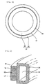
- the piston mainly comprises a piston body 11 shown in Fig. 1.
- the piston body 11 is cast using an aluminum alloy material, e.g., an Al-Si-base alloy, and has a cavity 12 defined therein and a piston pin bore 13 communicating with the cavity 12.
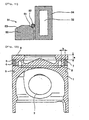
- a recess 15 is formed in a top surface 14 of the piston body 11, i.e., in an end surface of the piston body 11 facing a combustion chamber.
- a plurality of annular piston ring grooves 16, 17 and 18 are formed in an outer peripheral surface of the piston. Piston rings 19, 20 and 21 sliding over an inner peripheral surface of a cylinder (not shown) are assembled in the piston ring grooves 16, 17 and 18, respectively.
- the piston ring groove 18 most spaced from the top surface 14 is formed directly in the piston body 11, whereas the other piston ring grooves 16 and 17 are formed in a piston ring carrier 31 with a cooling cavity, which is separate from the piston body 11.
- the piston ring carrier 31 is integrally cast in the piston body 11 at the same time as when the piston body 11 is cast. Further, a cooling cavity 32 is formed in the piston ring carrier 31, allowing oil to flow therethrough for cooling, and a passage hole (not shown) for supplying oil to the cooling cavity 32 is formed in the piston body 11.
- the piston ring carrier 31 is fabricated by assembling an annular cavity forming member 34, which is formed of a metallic tubular material, to the inner periphery side of an annular ring carrier body 33 made of a metal-base sintered material. An enclosed space formed in the cavity forming member 34 defines the cooling cavity 32. Then, the ring carrier body 33 having the piston ring grooves 16 and 17 formed therein is made of a graphite precipitation iron-base sintered material.
- the iron-base sintered material contains Cr: 0.5 - 5 %, Mn: 0.2 - 1 %, S: 0.05 - 1 %, B: 0.05 - 1 %, C: 0.5 - 5 %, Ni: 1 - 12 %, Ti: 0.5 - 5 %, and Cu: 1 - 4 %. Also, it has such a structure that a matrix is mainly in austenite phase, and free graphite is precipitated and grown in pores.
- the composition of the sintered material is set such that the material is contracted with sintering. To realize this, by way of example, the content of Ni is increased.
- the cavity forming member 34 is made of ingot steel, e.g., austenitic stainless steel.
- An inner peripheral surface of the piston ring carrier 31 and an outer peripheral surface of the cavity forming member 34 are joined to each other by sinter-fitting and brazing (described later).
- the inner peripheral surface of the piston ring carrier 31 and the outer peripheral surface of the cavity forming member 34 are each in the form of a cylindrical surface. Further, the piston ring carrier 31 has an axial length almost equal to that of the cavity forming member 34.
- the cavity forming member 34 is obtained by, for example, pressing a tubular material into an annular member which has an outer peripheral surface shape in match with an inner peripheral surface shape of the ring carrier body 33. Both ends of the tubular material are abutted with each other and then welded while an enclosed space is defined in the cavity forming member 34 to serve as the cooling cavity 32.
- the ring carrier body 33 is manufactured by powder metallurgy.
- a powder compacted body as a blank of the ring carrier body 33 is formed from raw material powder (powder compacting step). More specifically, in this powder compacting step, the raw material powder is pressed and compressed using powder compacting press, thereby forming the powder compacted body.
- a compacting pressure is in the range of 5 - 7 t/cm 2 , and a density ratio of the powder compacted body having been thus formed is in the range of 80 - 95 %.
- the piston ring grooves 16 and 17 are not yet formed in the ring carrier body 33, and an outer peripheral surface of the ring carrier body 33 is in the form of a cylindrical surface, as shown in Figs. 2 and 3. Additionally, to form the piston ring grooves 16 and 17 later, the ring carrier body 33 is required to have some thickness.
- the cavity forming member 34 manufactured as described above is assembled to the inner periphery side of the ring carrier body 33 formed of the powder compacted body, and the ring carrier body 33 is heated and sintered along with the cavity forming member 34 in a sintering furnace (sintering step).
- a temperature in the sintering step is in the range of 1120 - 1150°C, and a sintering time is in the range of 30 minutes to 1 hour.
- denatured gas of natural gas, or N 2 -H 2 or ammonia decomposed gas is used as an atmosphere gas to form an endothermic reducing atmosphere.
- the ring carrier body 33 is contracted.
- the cavity forming member 34 made of stainless steel undergoes a less dimensional change than the ring carrier body 33. Accordingly, the ring carrier body 33 is tightly pressure-contacted with the cavity forming member 34, whereupon the ring carrier body 33 and the cavity forming member 34 are joined to each other. This is called sinter-fitting.
- the ring carrier body 33 and the cavity forming member 34 may be additionally brazed together (brazing step).
- cutouts 35 are formed in an upper inner peripheral surface of the ring carrier body 33 at several positions and tablet-shaped solder materials 36 are placed in the cutouts 35 in the powder compacting step.
- the solder material 36 is a copper-base material.
- the solder material contains Mn: 12.3 - 17.0 %, Ni: 29.3 - 41.3 %, Fe: 0.21 - 21.5 %, B: 0 - 1.47 %, Si: 0 - 2.00 %, C: 0.02 - 0.43 %, O 2 : 0.44 - 2.1 %, and the balance: Cu.
- the solder materials 36 are molten under heat produced upon the sintering, and the molten solder penetrates into the boundary between the ring carrier body 33 and the cavity forming member 34 with a capillary phenomenon.
- the ring carrier body 33 and the cavity forming member 34 are more positively joined to each other in combination with the above-described sinter-fitting.
- the sintering temperature is preferably set to fall in the range of 1130 - 1140°C.
- an aluminum alloy that is a similar material to that of the piston body 11 is infiltrated to the ring carrier body 33 formed of a sintered body (infiltrating step).
- the same aluminum alloy, i.e., AC8A or AC8C (according to Japanese Industrial Standards (JIS)), as used in the piston body 11, is employed as an infiltration material.
- the infiltrating step is carried out by vacuum impregnation. More specifically, the piston ring carrier 31 is held at temperatures in the range of 700 - 750°C and evacuated for about one hour in a vacuum vessel to remove gas from pores in the sintered body constituting the ring carrier body 33 so that the infiltration material is smoothly impregnated into the pores. Thereafter, the piston ring carrier 31 is immersed in a molten aluminum alloy and is held under pressure of 8 atm. for 5 - 60 minutes. As a result, the pores in the sintered body are impregnated with the aluminum alloy.
- the piston ring carrier 31 thus completed is cast in the piston body 11 at the same time as when the piston body 11 is cast under gravity (casting step).
- the piston ring carrier 31 is placed in a casting mold, and an Al-Si-base alloy as a material of the piston body 11 is molten and poured into the casting mold.
- the piston body 11 including the piston ring carrier 31 as an integral part is thereby formed.
- the piston ring grooves 16 and 17 are formed by mechanical machining (cutting) in the ring carrier body 33 that constitutes an outer peripheral portion of the piston ring carrier 31.
- the reason why the piston ring grooves 16 and 17 are formed by post-machining resides in improving accuracy in position and dimension of the piston ring grooves 16 and 17.
- the piston ring carrier 31 is constructed by combining the ring carrier body 33 and the cavity forming member 34 with each other and the cooling cavity 32 is formed in the piston ring carrier 31 by the inner space of the cavity forming member 34, the cooling cavity 32 can be positioned closer to the piston ring grooves 16, 17 and hence the piston rings 19, 20.
- the distance b between the cooling cavity 32 and the piston ring grooves 16, 17 can be reduced, and therefore a cooling effect can be enhanced. Accordingly, wear of the piston ring carrier 31 under high temperatures can be suppressed.
- the cavity forming member 34 can be easily assembled to the ring carrier body 33 in a more positively joined state between the ring carrier body 33 and the cavity forming member 34.
- the joining effect due to sinter-fitting can be maximally utilized because the axial length of the inner peripheral surface of the ring carrier body 33 is set almost equal to that of the cavity forming member 34.
- the joint between the ring carrier body 33 and the cavity forming member 34 can be realized with higher certainty. Since the brazing is performed at the same time as sintering the power compacted body, an increase in the number of manufacturing steps can be avoided.
- the cavity forming member 34 is constructed by the tubular member, no gap communicating with the cooling cavity 32 is left between the ring carrier body 33 and the cavity forming member 34, and the material of the piston body 11 is prevented from entering the cooling cavity 32 in the cavity forming member 34 during the casting step of casting the piston body 11, thus resulting in higher reliability. Since there is no need of welding the ring carrier body 33 and the cavity forming member 34 together, a production cost can be further cut down.
- the ring carrier body 33 in which the piston ring grooves 16 and 17 are formed is made of a metal-base sintered material, there are obtained such advantages that a shape of the ring carrier body 33 can be realized with comparatively high flexibility and a desired material can be selected from a comparatively wide range.
- a graphite precipitation iron-base sintered material can be used as the material of the ring carrier body 33 as described in the above embodiment.
- the graphite precipitation iron-base sintered material is superior in wear resistance at high temperatures, and has a coefficient of thermal expansion close to that of an Al-Si-base alloy as the material of the piston body 11, thereby providing higher joint strength with respect to the piston body 11. Additionally, an attacking property of the graphite precipitation iron-base sintered material against the combined part is small.
- the cavity forming member 34 is not required to have high wear resistance and hence can be easily and inexpensively manufactured from a metallic tubular material by pressing, etc.
- the cavity forming member 34 is heated during the sintering step, it is preferably made of a material that is endurable against the heat applied during the sintering step and exhibits a less dimensional change under the heating. From this point of view, austenitic stainless steel is suitable as the material of the cavity forming member 34.
- the piston ring carrier 31 with the cooling cavity can be provided which can ensure a high cooling effect, and which is superior in manufacturability and reliability.
- the present invention is not limited to the above first example, but can be implemented in various modified forms.
- the tablet-shaped solder materials 36 are placed for brazing in the cutouts 35 formed in the upper inner peripheral surface of the ring carrier body 33 at several positions.
- an annular groove 41 may be formed along the entire circumference of the upper inner peripheral surface of the ring carrier body 33, and a linear solder material 42 may be placed in the annular groove 41.
- the brazing can be achieved with higher certainty.
- the solder materials 36 are partly placed along the circumference, because the molten solder material 36 penetrates into the boundary between the ring carrier body 33 and the cavity forming member 34 with a capillary phenomenon.
- the solder material may be applied using a brush.
- the ring carrier body 33 and the cavity forming member 34 are joined to each other by not only the sinter-fitting based on contraction of the ring carrier body 33 upon sintering but also the brazing, they may be joined by the sinter-fitting alone. Conversely, they may be joined by the brazing alone.
- the piston ring carrier 31 can also be manufactured through the same steps as with the above first example, and similar working advantages to those in the above first example can be obtained except for the advantage attributable to the sinter-fitting.
- the sintered material of the ring carrier body 33 is not necessarily required to contract upon sintering.
- the axial length of the piston ring carrier 31 is set almost equal to that of the cavity forming member 34, both the axial lengths are not necessarily required to be equal.
- the axial length of the cavity forming member 34 may be greater than that of the piston ring carrier 31 for increasing the size of the cooling cavity 32. This arrangement contributes to enhancing the cooling effect.
- the solder material used as a material for the brazing may be in various forms such as a powder, powder compacted body, washer, wire, paste and foil.
- the solder material in the form of a powder compacted body is preferable, but the powder compacted body may have various forms such as a pellet and ring.
- a copper solder, phosphor copper solder, brass solder, silver solder, gold solder, palladium solder, aluminum solder, silver-copper-base solder (noble metal solder), nickel solder, copper-nickel-manganese-base solder, etc. are known as solder materials.
- the copper-nickel-manganese-base solder is particularly preferable.
- the copper-nickel-manganese-base solder contains, by weight %, Mn: 12 - 20 %, Ni: 25 - 45 %, Fe: 0 - 25 %, B: 0 - 1.5 %, Si: 0 - 2.0 %, C: 0.01 - 1.0 %, O 2 : 0.1 - 3.0 %, and the balance: Cu.
- a preferable composition is given by, by weight %, Mn: 16.2 %, Ni: 40.1 %, Fe: 0.21 %, B: 1.47 %, Si: 2.0 %, C: 0.03 %, O 2 : 0.44 %, and the balance: Cu.
- This powder composition is in terms of an alloy composition or a powder mixed composition. These two compositions may be combined with each other in use.
- the solder material has such characteristics as apparent density of 1.5 - 2.5 g/cm 2 , tapping density of 2.0 - 3.0 g/cm 2 , fluidity of 40 - 80 seconds/50 g, and compacted body density of 5.0 - 6.0 g/cm 2 and Rattle value of 0.5 - 60.0 % for compression of 6 ton /cm 2 .
- Preferable characteristics of the solder material are apparent density of 2.02 g/cm 2 , tapping density of 2.37 g/cm 2 , fluidity of 74 seconds/50 g, and compacted body density of 5.10 g/cm 2 and Rattle value of 52.0 % for compression of 6 ton /cm 2 .
- a gap c (shown in Fig. 6 in an exaggerated manner) between joined areas of the ring carrier body 33 and the cavity forming member 34 varies depending on the matrix (materials of the ring carrier body 33 and the cavity forming member 34) and the solder material used.
- the gap c at the joinend portion is preferably in the range of 0.01 - 0.8 mm from the viewpoints of joining fitness and joint strength, taking into account also the fact that the ring carrier body 33 is contracted upon sintering. If the gap c exceeds above 0.8 mm, voids would tend to occur more easily. If the gap c is smaller than 0.01 mm, filtration of the solder material would be deteriorated.
- a more preferable range of the gap c is 0.05 - 0.15 mm.
- the sintering temperature which also provides the joining temperature in the brazing, varies depending on the matrix and the solder material used, it is preferably in the range of 1130 - 1150°C when the ring carrier body 33 is made of an iron-base sintered material as with the above first example. In that temperature range, satisfactory joint due to the brazing can be achieved while maintaining satisfactory sintering.
- the sintering atmosphere which also provides the joining atmosphere in the brazing, varies depending on the matrix and the solder material used, and may be a vacuum, hydrogen, an ammonia decomposed atmosphere, etc.
- a nitrogen-base atmosphere N 2 : 80 - 99 %, H 2 : 1 - 20 %) that is an optimum atmosphere for sintered materials is preferable.
- a sintering furnace used for the sintering may be of, e.g., the continuous or box type
- a continuous furnace is particularly preferable when the ring carrier body 33 is made of an iron-base sintered material as with the above first example.
- Productivity can be improved by using a continuous furnace.
- the joined areas of the ring carrier body 33 and the cavity forming member 34 have surface roughness preferably in the range of 0.5 - 100 ⁇ m, more preferably in the range of 1.0 - 20 ⁇ m. In that surface roughness range, joining fitness and joint strength can be improved. It is also effective to optionally form ruggedness in the joined area surfaces by shot blasting, etc.
- the solder material can be arranged in any of various combinations depending on a shape of the solder material. Then, a shape of the ring carrier body may be changed depending on the composition and shape of the solder material.
- a tapered surface 51 is formed in an upper surface (one axial end surface) of the ring carrier body 33 at its inner peripheral portion so as to decline toward the inner periphery side, and the outer peripheral surface of the cavity forming member 34 is positioned so as to project upward beyond the tapered surface 51 of the ring carrier body 33.
- the solder material 52 in the form of, e.g., a pellet, ring, paste or wire is arranged in a groove formed between the tapered surface 51 of the ring carrier body 33 and the outer peripheral surface of the cavity forming member 34. Furthermore, in the fifth example shown in Fig. 7, a tapered surface 53 is formed in the upper surface of the ring carrier body 33 at its outer peripheral portion so as to decline toward the outer periphery side. In a sixth example shown in Fig. 8, the solder material 52 in the form of, e.g., a paste, foil or powder is put in a gap between the cylindrical inner peripheral surface of the ring carrier body 33 and the cylindrical outer peripheral surface of the cavity forming member 34 in the brazing step.
- a stepped portion 54 is formed in the upper inner peripheral portion of the ring carrier body 33. Then, in the brazing step, the solder material 52 in the form of, e.g., a pellet, ring, washer or paste is arranged in a groove formed between the stepped portion 54 of the ring carrier body 33 and the outer peripheral surface of the cavity forming member 34. Further, in an eighth example shown in Fig. 10, a stepped portion 54 is formed in the upper inner peripheral portion of the ring carrier body 33.
- the solder material 52 in the form of, e.g., a pellet, ring, paste or foil is arranged to have an L-shaped section in a groove formed between the stepped portion 54 of the ring carrier body 33 and the outer peripheral surface of the cavity forming member 34.
- the fourth and fifth examples are preferable and, in particular, the fifth example is more preferable.
- the molten solder material 52 is guided by the tapered surface 51 to surely enter the gap between the ring carrier body 33 and the cavity forming member 34 in the brazing step. As a result, the brazing can be achieved with higher certainty.
- the ring carrier body 33 is positioned to face a central area of the cavity forming member 34 in the axial (vertical) direction
- the ring carrier body 33 and the cavity forming member 34 may be positioned such that their lower surfaces are flush with each other as implemented by an eleventh example shown in Fig. 11.
- the shape of the ring carrier body, the shape of the cavity forming member, and/or the shape of the entire piston ring carrier are not limited to those shown in the above examples, those shapes may be variously changed.
- the materials and manufacturing methods of the ring carrier body and the cavity forming member are not limited in their details to those described above, but may be modified in various ways.
- the arrangement of the solder material is not limited to the above examples, but the shapes of the solder material and the ring carrier body may be selected from various combinations. It is essential that those shapes be selected to be optimum for the joint between the ring carrier body and the cavity forming member.
- an annular cavity forming member made of a tubular material is assembled to the inner periphery side of an annular ring carrier body made of a metal-base sintered material, and a cooling cavity is formed by an enclosed space in the cavity forming member. Therefore, the cooling cavity can be positioned closer to a piston ring and a cooling effect can be enhanced. Also, since the cavity forming member is constructed by the tubular material, a material of the piston body is prevented from entering the cooling cavity in the cavity forming member during a casting step of the piston body, thus resulting in higher reliability.
- the ring carrier body is made of a sintered material capable of contracting upon sintering and the ring carrier body and the cavity forming member are joined to each other by sinter-fitting, the cavity forming member and the ring carrier body can be easily and positively joined to each other.
- the ring carrier body is made of the metal-base sintered material, it is possible to realize a desired shape of the ring carrier body with high flexibility, and to select, for example, a material that is superior in wear resistance at high temperatures and has a coefficient of thermal expansion close to that of the material of the piston body. Additionally, compatibility of the piston ring carrier with the piston body in the casting-in step can be improved by infiltration, etc.
- the ring carrier body and the cavity forming member are joined to each other by brazing, the ring carrier body and the cavity forming member are joined to each other with higher certainty in addition to the above advantages.
- an annular cavity forming member made of a tubular material is assembled to the inner periphery side of an annular ring carrier body made of a metal-base sintered material, and a cooling cavity is formed by an enclosed space in the cavity forming member. Therefore, the cooling cavity can be positioned closer to a piston ring and a cooling effect can be enhanced. Also, since the cavity forming member is constructed by the tubular material, a material of the piston body is prevented from entering the cooling cavity in the cavity forming member during a casting step of the piston body, thus resulting in higher reliability.
- the ring carrier body and the cavity forming member are joined to each other by brazing, they can be brazed, for example, at the same time as sintering. Accordingly, the ring carrier body and the cavity forming member can be easily and positively joined to each other.
- the ring carrier body is made of the metal-base sintered material, it is possible to realize a desired shape of the ring carrier body with high flexibility, and to select, for example, a material that is superior in wear resistance at high temperatures and has a coefficient of thermal expansion close to that of the material of the piston body. Additionally, compatibility of the piston ring carrier with the piston body in the casting-in step can be improved by infiltration, etc.
- a solder material for the brazing is a copper-nickel-manganese-base solder
- the molten solder material is suppressed, for example, from penetrating into the metal-base sintered material, and satisfactory brazing can be achieved in addition to the above advantages.
- joined areas of the ring carrier body and the cavity forming member have surface roughness in the range of 0.5 - 100 ⁇ m, joining fitness and joint strength with the brazing can be improved in addition to the above advantages.
- a preferable surface roughness range of the joined areas is 1 - 20 ⁇ m.
- the brazing can be achieved with higher certainty by arranging the solder material in a groove formed between the tapered surface of the ring carrier body and the outer peripheral surface of the cavity forming member in the brazing, in addition to the above advantages.
- the method comprises the steps of compressing raw material powder containing a metal as a main component to form a powder compacted body which becomes an annular ring carrier body receiving the piston ring assembled to the piston ring carrier; assembling an annular, metal-made cavity forming member to the inner periphery side of the powder compacted body; sintering the powder compacted body along with the cavity forming member; and joining a sintered body obtained by sintering the powder compacted body and the cavity forming member to each other based on contraction of the powder compacted body occurred upon sintering, whereby the cooling cavity is formed by an enclosed space in the cavity forming member.
- the cooling cavity can be positioned closer to the piston ring and a cooling effect can be enhanced.
- the ring carrier body and the cavity forming member having the cooling cavity formed therein can be easily and positively joined to each other.
- the cavity forming member is constructed by the tubular material, a material of the piston body is prevented from entering the cooling cavity in the cavity forming member during the casting step of the piston body, thus resulting in higher reliability.
- the ring carrier body is made of a metal-base sintered material, it is possible to select, for example, a material that is superior in wear resistance at high temperatures and has a coefficient of thermal expansion close to that of the material of the piston body. Additionally, compatibility of the piston ring carrier with the piston body in the casting-in step can be improved by infiltration, etc.
- the joint between the ring carrier body and the cavity forming member can be made more positive while an increase in the number of manufacturing steps is suppressed, in addition to the above advantages.
- the method comprises the steps of compressing raw material powder containing a metal as a main component to form a powder compacted body which becomes an annular ring carrier body receiving the piston ring assembled to the piston ring carrier; assembling an annular cavity forming member made of a tubular material to the inner periphery side of the powder compacted body; sintering the powder compacted body along with the cavity forming member; and joining a sintered body obtained by sintering the powder compacted body and the cavity forming member to each other by brazing during the sintering step, whereby the cooling cavity is formed by an enclosed space in the cavity forming member.
- the cooling cavity can be positioned closer to the piston ring and a cooling effect can be enhanced.
- the ring carrier body and the cavity forming member having the cooling cavity formed therein can be easily and positively joined to each other.
- the cavity forming member is constructed by the tubular material, a material of the piston body is prevented from entering the cooling cavity in the cavity forming member during the casting step of the piston body, thus resulting in higher reliability.
- the ring carrier body is made of a metal-base sintered material, it is possible to select, for example, a material that is superior in wear resistance at high temperatures and has a coefficient of thermal expansion close to that of the material of the piston body. Additionally, compatibility of the piston ring carrier with the piston body in the casting-in step can be improved by infiltration, etc.
- a copper-nickel-manganese-base solder is used as a solder material for the brazing, the molten solder material is suppressed, for example, from penetrating into the metal-base sintered material, and satisfactory brazing can be achieved in addition to the above advantages.
- a gap between joined areas of the ring carrier body and the cavity forming member, which are brazed to each other is in the range of 0.01 - 0.8 mm, joining fitness and joint strength with the brazing can be improved in addition to the above advantages.
- a preferable gap range between the joined areas is 0.05 - 0.15 mm.
- a sintering temperature is in the range of 1130 - 1150°C, satisfactory joint can be achieved by the brazing while satisfactory sintering is maintained, in addition to the above advantages.
- a sintering atmosphere is a nitrogen-base atmosphere, satisfactory joint can be achieved by the brazing while satisfactory sintering is maintained, in addition to the above advantages.
- joined areas of the ring carrier body and the cavity forming member have surface roughness in the range of 0.5 - 100 ⁇ m, joining fitness and joint strength with the brazing can be improved in addition to the above advantages.
- a preferable surface roughness range of the joined areas is 1.0 - 20 ⁇ m.
- the brazing can be achieved with higher certainty by arranging the solder material in a groove formed between the tapered surface of the ring carrier body and the outer peripheral surface of the cavity forming member in the brazing, in addition to the above advantages.
Landscapes
- Engineering & Computer Science (AREA)
- General Engineering & Computer Science (AREA)
- Mechanical Engineering (AREA)
- Chemical & Material Sciences (AREA)
- Combustion & Propulsion (AREA)
- Physics & Mathematics (AREA)
- Fluid Mechanics (AREA)
- Pistons, Piston Rings, And Cylinders (AREA)
- Powder Metallurgy (AREA)
Claims (10)
- Kolbenringträger (31) mit einem Kühlhohlraum (32) zum Gießen in einen Kolbenkörper (11) und zum Aufnehmen eines Kolbenringes (19, 20), dadurch gekennzeichnet, dass der Kolbenringträger einen ringförmigen Ringträgerkörper (33) aus einem metallbasierten, gesinterten Material zum Aufnehmen des Kolbenringes (19, 20); und ein ringförmiges, hohlraumbildendes Element (34) aus röhrenförmigem Material, das mit dem inneren Umfang des Ringträgerkörpers verbunden ist, aufweist, wobei der Ringträgerkörper aus einem Material ist, das bei einem Sintern kontrahierbar ist, um den Ringträgerkörper und das hohlraumbildende Element durch eine Sinterpassverbindung zu verbinden, wobei der Kühlhohlraum durch den umschlossenen Raum in dem hohlraumbildenden Element vorgesehen ist, wobei eine innere Umfangsfläche des Kolbenringträgers (31) und eine äußere Umfangsfläche des hohlraumbildenden Elements (34) in der Form einer zylindrischen Fläche sind, und die innere Umfangsfläche des Kolbenringträgers (31) und die äußere Umfangsfläche des hohlraumbildenden Elements (34) sind ohne Spalt dazwischen verbunden.
- Kolbenringträger mit einem Kühlhohlraum nach Anspruch 1, bei welchem der Ringträgerkörper und das hohlraumbildende Element miteinander durch Löten verbindbar sind.
- Kolbenringträger (31) mit einem Kühlhohlraum (32) zum Gießen in einen Kolbenkörper und mit welchem ein Kolbenring (19, 20) verbunden ist, dadurch gekennzeichnet, dass der Kolbenringträger einen ringförmigen Ringträgerkörper (33) aus einem metallbasierten, gesinterten Material zum Aufnehmen des Kolbenrings (19, 20) und ein ringförmiges, hohlraumbildendes Element (34) aus einem röhrenförmigen Material, das mit dem inneren Umfang des Ringträgerkörpers verbunden ist, aufweist, wobei eine Lötverbindung zwischen dem Ringträgerkörper und dem hohlraumbildenden Element vorgesehen ist, und wobei der Kühlhohlraum ein umschlossener Raum in dem hohlraumbildenden Element ist, wobei eine innere Umfangsfläche des Kolbenringträgers (31) und eine äußere Umfangsfläche des hohlraumbildenden Elements (34) in der Form einer zylindrischen Fläche sind, und die innere Umfangsfläche des Kolbenringträgers (31) und die äußere Umfangsfläche des hohlraumbildenden Elements (34) sind ohne Spalt dazwischen verbunden.
- Kolbenringträger mit einem Kühlhohlraum nach Anspruch 3, bei welchem ein Lötmaterial für das Löten ein Kupfer-Nickel-Mangan-basiertes Lötmaterial ist.
- Kolbenringträger mit einem Kühlhohlraum nach Anspruch 3, bei welchem die verbindbaren Bereiche des Ringträgerkörpers und des hohlraumbildenden Elements eine Oberflächenrauhigkeit im Bereich von 0,5 - 100 µm besitzen.
- Kolbenringträger mit einem Kühlhohlraum nach Anspruch 3, bei welchem eine verjüngte Fläche (51) in einem oberen, inneren Umfangsabschnitt des Ringträgerkörpers derart vorgesehen ist, um sich zu der Seite des inneren Umfangs hin zu neigen, und eine äußere Umfangsfläche des hohlraumbildenden Elements steht nach oben über die verjüngte Fläche des Ringträgerkörpers hervor.
- Verfahren zum Herstellen eines Kolbenringträgers (31) mit einem Kühlhohlraum (32), der in einen Kolbenkörper (11) gegossen ist und an welchem ein Kolbenring (19, 20, 21) angebracht ist, dadurch gekennzeichnet, dass das Verfahren die Schritte aufweist:wobei der Kühlhohlraum durch einen umschlossenen Raum in dem hohlraumbildenden Element gebildet wird.Komprimieren eines Rohmaterialpulvers, das ein Metall als Hauptkomponente enthält, um einen pulververdichteten Körper zu bilden, der ein ringförmiger Ringträgerkörper (33) wird, welcher den Kolbenring (19, 20) aufnimmt, welcher an dem Kolbenringträger angebracht wird;Anbringen eines ringförmigen, hohlraumbildenden Elements (34), das aus einem röhrenförmigen Material hergestellt ist, seitens des inneren Umfangs des pulververdichteten Körpers;Sintern des pulververdichteten Körpers zusammen mit dem hohlraumbildenden Element; undVerbinden eines durch Sintern des pulververdichteten Körpers und des hohlraumbildenden Elements miteinander erhaltenen, gesinterten Körpers basierend auf einer Kontraktion des pulververdichteten Körpers, die beim Sintern auftritt,
- Verfahren zum Herstellen eines Kolbenringträgers mit einem Kühlhohlraum nach Anspruch 7, bei welchem der Ringträgerkörper und das hohlraumbildende Element miteinander während des Sinterschritts verlötet werden.
- Verfahren zum Herstellen eines Kolbenringträgers (31) mit einem Kühlhohlraum (32), der in einen Kolbenkörper (11) gegossen ist und an welchem ein Kolbenring (19, 20, 21) angebracht ist, dadurch gekennzeichnet, dass das Verfahren die Schritte aufweist:wobei der Kühlhohlraum durch einen umschlossenen Raum in dem hohlraumbildenden Element gebildet wird.Komprimieren eines Rohmaterialpulvers, das ein Metall als Hauptkomponente enthält, um einen pulververdichteten Körper zu bilden, der ein ringförmiger Ringträgerkörper (33) wird, welcher den Kolbenring (19, 20) aufnimmt, der an dem Kolbenringträger angebracht wird;Anbringen eines ringförmigen hohlraumbildenden Elements (34), das aus einem röhrenförmigen Material hergestellt ist, seitens des inneren Umfangs des pulververdichteten Körpers; undSintern des pulververdichteten Körpers zusammen mit dem hohlraumbildenden Element; undVerbinden eines durch Sintern des pulververdichteten Körpers und des hohlraumbildenden Elements miteinander erhaltenen, gesinterten Körpers durch Verlöten während des Sinterschritts,
- Verfahren zum Herstellen eines Kolbenringträgers mit einem Kühlhohlraum nach Anspruch 9, bei welchem ein aus einem pulververdichteten Körper gebildetes Lötmaterial als Lötmaterial für das Löten verwendet wird.
Applications Claiming Priority (4)
| Application Number | Priority Date | Filing Date | Title |
|---|---|---|---|
| JP13477299 | 1999-05-14 | ||
| JP13477299 | 1999-05-14 | ||
| JP2000130103A JP2001032748A (ja) | 1999-05-14 | 2000-04-28 | 冷却空洞付きピストン耐摩環およびその製造方法 |
| JP2000130103 | 2000-04-28 |
Publications (3)
| Publication Number | Publication Date |
|---|---|
| EP1052435A2 EP1052435A2 (de) | 2000-11-15 |
| EP1052435A3 EP1052435A3 (de) | 2002-02-27 |
| EP1052435B1 true EP1052435B1 (de) | 2004-11-17 |
Family
ID=26468783
Family Applications (1)
| Application Number | Title | Priority Date | Filing Date |
|---|---|---|---|
| EP20000110151 Expired - Lifetime EP1052435B1 (de) | 1999-05-14 | 2000-05-12 | Kolbenringträger mit Kühlhohlraum und Verfahren zu dessen Herstellung |
Country Status (3)
| Country | Link |
|---|---|
| EP (1) | EP1052435B1 (de) |
| JP (1) | JP2001032748A (de) |
| DE (1) | DE60015846T2 (de) |
Cited By (3)
| Publication number | Priority date | Publication date | Assignee | Title |
|---|---|---|---|---|
| DE102006043301A1 (de) * | 2006-09-14 | 2008-03-27 | Mahle International Gmbh | Ringträger und Verfahren zu seiner Herstellung |
| DE102006043302A1 (de) * | 2006-09-14 | 2008-03-27 | Mahle International Gmbh | Ringträger und Verfahren zu seiner Herstellung |
| RU184035U1 (ru) * | 2018-02-06 | 2018-10-12 | Ильгиз Асгатович Шамсиев | Поршень дизельного двигателя внутреннего сгорания |
Families Citing this family (11)
| Publication number | Priority date | Publication date | Assignee | Title |
|---|---|---|---|---|
| FR2818317A1 (fr) * | 2000-12-19 | 2002-06-21 | Renault | Piston equipe d'une bague avec canal de refroidissement portant plusieurs segments |
| DE10352244A1 (de) * | 2003-11-08 | 2005-06-09 | Mahle Gmbh | Verfahren zur Herstellung eines Kolbens für einen Verbrennungsmotor |
| DE102004057558A1 (de) * | 2004-11-30 | 2006-06-01 | Mahle International Gmbh | Kolben für einen Verbrennungsmotor |
| DE102007010839B4 (de) * | 2007-03-06 | 2009-02-05 | Federal-Mogul Nürnberg GmbH | Verfahren zur Herstellung eines Kolbens und Kolben mit einer ringförmigen Verstärkung bestehend aus mehreren Verstärkungssegmenten |
| DE102007061601A1 (de) | 2007-12-20 | 2009-06-25 | Mahle International Gmbh | Kolben für einen Verbrennungsmotor sowie Verfahren zu seiner Herstellung |
| DE102008031864A1 (de) * | 2008-07-05 | 2010-01-07 | Mahle International Gmbh | Einlegteil für einen Kolben eines Verbrennungsmotors sowie mit dem Einlegeteil versehener Kolben oder Kolbenkopf |
| DE102009005397B4 (de) * | 2009-01-19 | 2011-02-17 | Manfred Wanzke | Pleuelkolbenkompressor mit drehteilsegmentförmiger Dichtung |
| RU2453399C2 (ru) * | 2010-07-13 | 2012-06-20 | федеральное государственное бюджетное образовательное учреждение высшего профессионального образования "Южно-Российский государственный технический университет (Новочеркасский политехнический институт)" | Способ изготовления порошковых поршневых колец |
| KR101280000B1 (ko) | 2011-01-31 | 2013-07-17 | 주식회사 티엠시 | 디젤 엔진 피스톤용 오일 갤러리 접합 소결 인서트링의 제조 방법 및 이를 이용한 오일 갤러리 접합 소결 인서트링 일체형 피스톤 |
| KR101874560B1 (ko) * | 2016-12-08 | 2018-07-04 | 동양피스톤 주식회사 | 차량 엔진용 피스톤 및 차량 엔진용 피스톤의 제조 방법 |
| CN113454260A (zh) * | 2018-11-20 | 2021-09-28 | Ks科尔本施密特有限公司 | 用于内燃机的构件的覆层的材料成分组合 |
Family Cites Families (6)
| Publication number | Priority date | Publication date | Assignee | Title |
|---|---|---|---|---|
| FR1244722A (fr) * | 1959-02-24 | 1960-10-28 | Mahle Kg | Piston en métal léger pour moteurs à combustion interne, et son procédé de fabrication |
| JPS5852346A (ja) | 1981-09-24 | 1983-03-28 | Kuraray Co Ltd | 雲母充填ポリエステル組成物の製造法 |
| DE3927509A1 (de) * | 1989-08-21 | 1991-02-28 | Mahle Gmbh | Fluessiggepresster leichtmetall-tauchkolben mit einer ringfoermigen verstaerkungseinlage im ringnutenbereich |
| JPH05240347A (ja) | 1992-02-26 | 1993-09-17 | Hino Motors Ltd | エンジン用ピストン耐摩環 |
| US5979298A (en) * | 1997-05-08 | 1999-11-09 | Zellner Pistons, Llc | Cooling gallery for pistons |
| DE19722053C2 (de) * | 1997-05-27 | 2002-10-24 | Ks Kolbenschmidt Gmbh | Kolben für einen Verbrennungsmotor |
-
2000
- 2000-04-28 JP JP2000130103A patent/JP2001032748A/ja active Pending
- 2000-05-12 DE DE2000615846 patent/DE60015846T2/de not_active Expired - Fee Related
- 2000-05-12 EP EP20000110151 patent/EP1052435B1/de not_active Expired - Lifetime
Cited By (3)
| Publication number | Priority date | Publication date | Assignee | Title |
|---|---|---|---|---|
| DE102006043301A1 (de) * | 2006-09-14 | 2008-03-27 | Mahle International Gmbh | Ringträger und Verfahren zu seiner Herstellung |
| DE102006043302A1 (de) * | 2006-09-14 | 2008-03-27 | Mahle International Gmbh | Ringträger und Verfahren zu seiner Herstellung |
| RU184035U1 (ru) * | 2018-02-06 | 2018-10-12 | Ильгиз Асгатович Шамсиев | Поршень дизельного двигателя внутреннего сгорания |
Also Published As
| Publication number | Publication date |
|---|---|
| EP1052435A3 (de) | 2002-02-27 |
| DE60015846T2 (de) | 2005-10-20 |
| JP2001032748A (ja) | 2001-02-06 |
| EP1052435A2 (de) | 2000-11-15 |
| DE60015846D1 (de) | 2004-12-23 |
Similar Documents
| Publication | Publication Date | Title |
|---|---|---|
| EP1052435B1 (de) | Kolbenringträger mit Kühlhohlraum und Verfahren zu dessen Herstellung | |
| US8074617B2 (en) | Piston for an internal combustion engine and method for its production | |
| EP0261726A2 (de) | Kolben | |
| KR20150036357A (ko) | 열전도율이 높은 밸브 시트 링 | |
| JPH0419345A (ja) | 内燃機関用のシリンダブロック、およびそれを製造する方法 | |
| US4556532A (en) | Method for manufacturing camshaft | |
| CN105873699A (zh) | 双层/三层阀导承 | |
| JPS6039105A (ja) | カムシヤフト及びその製造方法 | |
| US5341866A (en) | Method for the incorporation of a component into a piston | |
| US4972898A (en) | Method of forming a piston containing a cavity | |
| JP2011505513A (ja) | 多重ピースからなる薄肉の金属粉末シリンダライナー | |
| JPS5841211A (ja) | カムシヤフト | |
| JP3749809B2 (ja) | 高温耐摩耗性および熱伝導性の優れた冷却空洞付きピストンリング複合耐摩環 | |
| JP2003090432A (ja) | 冷却空洞付き耐摩環およびその製造方法 | |
| JP2000145539A (ja) | 冷却空洞付きピストン耐摩環およびその製造方法 | |
| KR101424007B1 (ko) | 디젤 엔진 피스톤용 오일 갤러리 접합 소결 인서트링 및 이의 제조 방법과 이를 이용한 오일 갤러리 접합 소결 인서트링 일체형 피스톤 | |
| JP2000145540A (ja) | 冷却空洞付きピストン耐摩環およびその製造方法 | |
| JPH07317512A (ja) | 弁座およびその製造方法 | |
| JP4278138B2 (ja) | 冷却空洞付き耐摩環 | |
| JPS6246803Y2 (de) | ||
| JP2000145541A (ja) | 冷却空洞付きピストン耐摩環およびその製造方法 | |
| JP2001329305A (ja) | 多孔質金属焼結体よりなる耐摩環 | |
| JP2560402B2 (ja) | 内燃機関のピストン | |
| JP2002147606A (ja) | 冷却空洞付きピストン耐摩環およびその製造方法 | |
| JPS6132082Y2 (de) |
Legal Events
| Date | Code | Title | Description |
|---|---|---|---|
| PUAI | Public reference made under article 153(3) epc to a published international application that has entered the european phase |
Free format text: ORIGINAL CODE: 0009012 |
|
| AK | Designated contracting states |
Kind code of ref document: A2 Designated state(s): AT BE CH CY DE DK ES FI FR GB GR IE IT LI LU MC NL PT SE Kind code of ref document: A2 Designated state(s): DE FR |
|
| AX | Request for extension of the european patent |
Free format text: AL;LT;LV;MK;RO;SI |
|
| PUAL | Search report despatched |
Free format text: ORIGINAL CODE: 0009013 |
|
| AK | Designated contracting states |
Kind code of ref document: A3 Designated state(s): AT BE CH CY DE DK ES FI FR GB GR IE IT LI LU MC NL PT SE |
|
| AX | Request for extension of the european patent |
Free format text: AL;LT;LV;MK;RO;SI |
|
| RIC1 | Information provided on ipc code assigned before grant |
Free format text: 7F 16J 9/00 A, 7F 16J 9/22 B |
|
| 17P | Request for examination filed |
Effective date: 20020730 |
|
| 17Q | First examination report despatched |
Effective date: 20020927 |
|
| AKX | Designation fees paid |
Free format text: DE FR |
|
| RAP1 | Party data changed (applicant data changed or rights of an application transferred) |
Owner name: MITSUBISHI MATERIALS CORPORATION Owner name: MITSUBISHI FUSO TRUCK AND BUS CORPORATION |
|
| RAP1 | Party data changed (applicant data changed or rights of an application transferred) |
Owner name: MITSUBISHI MATERIALS CORPORATION Owner name: MITSUBISHI FUSO TRUCK AND BUS CORPORATION |
|
| GRAP | Despatch of communication of intention to grant a patent |
Free format text: ORIGINAL CODE: EPIDOSNIGR1 |
|
| GRAS | Grant fee paid |
Free format text: ORIGINAL CODE: EPIDOSNIGR3 |
|
| GRAA | (expected) grant |
Free format text: ORIGINAL CODE: 0009210 |
|
| AK | Designated contracting states |
Kind code of ref document: B1 Designated state(s): DE FR |
|
| REG | Reference to a national code |
Ref country code: IE Ref legal event code: FG4D |
|
| REF | Corresponds to: |
Ref document number: 60015846 Country of ref document: DE Date of ref document: 20041223 Kind code of ref document: P |
|
| PLBE | No opposition filed within time limit |
Free format text: ORIGINAL CODE: 0009261 |
|
| STAA | Information on the status of an ep patent application or granted ep patent |
Free format text: STATUS: NO OPPOSITION FILED WITHIN TIME LIMIT |
|
| ET | Fr: translation filed | ||
| 26N | No opposition filed |
Effective date: 20050818 |
|
| REG | Reference to a national code |
Ref country code: FR Ref legal event code: TP |
|
| PGFP | Annual fee paid to national office [announced via postgrant information from national office to epo] |
Ref country code: DE Payment date: 20070523 Year of fee payment: 8 |
|
| PGFP | Annual fee paid to national office [announced via postgrant information from national office to epo] |
Ref country code: FR Payment date: 20070524 Year of fee payment: 8 |
|
| REG | Reference to a national code |
Ref country code: FR Ref legal event code: ST Effective date: 20090119 |
|
| PG25 | Lapsed in a contracting state [announced via postgrant information from national office to epo] |
Ref country code: DE Free format text: LAPSE BECAUSE OF NON-PAYMENT OF DUE FEES Effective date: 20081202 Ref country code: FR Free format text: LAPSE BECAUSE OF NON-PAYMENT OF DUE FEES Effective date: 20080602 |