EP1049584B1 - Procede et dispositif pour empecher une propagation incontrolee de poudre dans une machine a imprimer - Google Patents
Procede et dispositif pour empecher une propagation incontrolee de poudre dans une machine a imprimer Download PDFInfo
- Publication number
- EP1049584B1 EP1049584B1 EP99908798A EP99908798A EP1049584B1 EP 1049584 B1 EP1049584 B1 EP 1049584B1 EP 99908798 A EP99908798 A EP 99908798A EP 99908798 A EP99908798 A EP 99908798A EP 1049584 B1 EP1049584 B1 EP 1049584B1
- Authority
- EP
- European Patent Office
- Prior art keywords
- air
- powder
- sheet
- sheet delivery
- housing
- Prior art date
- Legal status (The legal status is an assumption and is not a legal conclusion. Google has not performed a legal analysis and makes no representation as to the accuracy of the status listed.)
- Expired - Lifetime
Links
Images
Classifications
-
- B—PERFORMING OPERATIONS; TRANSPORTING
- B41—PRINTING; LINING MACHINES; TYPEWRITERS; STAMPS
- B41F—PRINTING MACHINES OR PRESSES
- B41F23/00—Devices for treating the surfaces of sheets, webs, or other articles in connection with printing
- B41F23/04—Devices for treating the surfaces of sheets, webs, or other articles in connection with printing by heat drying, by cooling, by applying powders
- B41F23/044—Drying sheets, e.g. between two printing stations
- B41F23/0443—Drying sheets, e.g. between two printing stations after printing
-
- B—PERFORMING OPERATIONS; TRANSPORTING
- B41—PRINTING; LINING MACHINES; TYPEWRITERS; STAMPS
- B41F—PRINTING MACHINES OR PRESSES
- B41F23/00—Devices for treating the surfaces of sheets, webs, or other articles in connection with printing
- B41F23/04—Devices for treating the surfaces of sheets, webs, or other articles in connection with printing by heat drying, by cooling, by applying powders
- B41F23/06—Powdering devices, e.g. for preventing set-off
-
- B—PERFORMING OPERATIONS; TRANSPORTING
- B65—CONVEYING; PACKING; STORING; HANDLING THIN OR FILAMENTARY MATERIAL
- B65H—HANDLING THIN OR FILAMENTARY MATERIAL, e.g. SHEETS, WEBS, CABLES
- B65H29/00—Delivering or advancing articles from machines; Advancing articles to or into piles
- B65H29/24—Delivering or advancing articles from machines; Advancing articles to or into piles by air blast or suction apparatus
- B65H29/245—Air blast devices
- B65H29/246—Air blast devices acting on stacking devices
- B65H29/247—Air blast devices acting on stacking devices blowing on upperside of the sheet
Definitions
- the invention relates to a method and an apparatus for Prevent an uncontrolled spread of powder in one Press.
- the invention relates in particular to a Process in which sheets printed in a sheet-fed printing machine by means of a sheet conveyor through a sheet delivery conveyed through a stack of sheets and with one Powder are dusted and one is uncontrolled Spread of excess powder is prevented, as well a device for preventing an uncontrolled Spreading powder in a sheet delivery case a sheet printing machine that a sheet conveyor for Transport of printed sheets via a sheet stack and a dusting device for dusting the printed Powder surrounds bow.
- the invention relates above also a sheet delivery for a sheet printing machine and a Sheet printing machine with such a device.
- a paper or chain conveyor Sheet delivery i.e. a chain conveyor with two parallel, connected by delivery gripper systems or sheet grippers Chains included and within a the sheet delivery and enclosing the printing units of the printing press housing transported a stack of sheets on which she then are stacked on top of each other. Since the printing ink at The sheets are not yet completely stacked on top of one another is dried at most on the market located sheetfed offset presses at least one Surface of each sheet before placing it on the stack with powdered on the printed areas of the Sheets of paper stick and a deposit, i.e.
- a sticking together the sheet of paper in the sheet stack prevents.
- Be as powder usually fine powdered potato starch or others powdered starch products used.
- To apply the Powder serves a so-called powder device or another Pollination facility, usually in a space between the leading leading the sheets Conveyor strand and the returning empty strand of the chain conveyor is arranged and the on the lower conveyor run of the Chain conveyor transported sheets from above with dusted the powder.
- High-speed sheetfed offset presses for printing high Requirements such as those under the label Heidelberg Speedmaster from Heidelberger Druckmaschinen AG sheetfed offset presses are usually sold with a high-stack sheet delivery to stack more sheets to be able to. With such sheet displays, this extends Chain conveyor conveyor run first diagonally upwards and is then redirected into the horizontal to the printed Sheets horizontally before releasing them above the sheet filing stack align.
- the pollination facility is common there just before the upper end of the sloping section of the Funding runs in the space between this and the empty run arranged of the chain conveyor.
- a sheet delivery is a Sheet printing machine disclosed in the housing near the Powder dusting device above the conveyor belt devices are provided to suck off excess powder and thus to prevent its uncontrolled spread.
- Such Devices suck a large part of the powder applied immediately, which often has the consequence that the Operating personnel increases the powder supply and so much more Powder is consumed.
- the problem of powder spread an air suction inside the housing, however unsolved.
- a sheet delivery is a Printing machine disclosed in the along an upper horizontal section of the empty run of a sheet conveyor a cleaning device is provided which has a housing, several brushes arranged in the housing and one Suction device includes the brushes from the Vacuum chains and gripper systems of cleaned powder.
- the cleaning device described is still suitable to transport powder-laden air in the direction to prevent the printing press, since both between the Housing of the cleaning device and the adjacent walls the sheet delivery as well as inside the case on both Wide open flow cross-sections on the sides of the brushes are present that have a passage of powdered Allow air along the movement path of the empty run.
- the invention is based on the object a method and a retrofittable and / or Factory assembled device of the type mentioned To provide a during printing Reduction of dust pollution in the vicinity of the Printing machine enables and the formation of powder deposits largely prevented within the housing.
- the invention provides that everyone along the movement path of the empty strand Existing flow path through which powder-contaminated air from the free end of the sheet delivery can flow to the printing press, at least one place between the free end of the Delivery and the printing press is blocked to allow the Formation of a running in the direction of the printing press Air flow and thus a transport of powder in it To prevent air flow to the press. It is for that required the entire free at the point of interruption Flow cross-section between an upper wall of the housing, the two side walls of the housing and one in the space arranged between the empty strand and the conveyor strand Partition or the like essentially completely block so that a passage of powdered air through this section of the flow path almost completely is prevented.
- the air flow is as close as possible to the free end of the Sheet delivery interrupted, i.e. expedient in an upper horizontal section of the sheet delivery and preferably above from a drive shaft of a lifting mechanism for the Sheet storage stack, where there is enough space for the required Facilities is available. Because the drive shaft is very turns slowly, it can also serve as a support or carrier for serve part of the facilities.
- the air flow can be interrupted with pneumatic and / or by mechanical means, one Combination is preferred.
- an interruption with pneumatic means is preferred air at the Interruption point sucked out of the housing and / or a Electricity cleaner, i.e. air not contaminated with powder so in that Housing of the sheet delivery fed that the flow path is blocked by an air curtain or airflow that the Empty strand is interspersed and is sufficiently wide and deep to a passage of powdered air between the top wall of the housing, the two side walls of the housing and that arranged between the empty run and the conveyor run Prevent partition or the like.
- an air supply device which Air sucked in from the environment and not contaminated with powder conducts into the housing so that it crosses the empty strand to it Flow direction vertical
- Air extraction device which is transverse to the direction of movement of the Empty strand sucks air from the flow path, preferably opposite the air supply device by at least one Part of the air introduced together with that from the chains and sheet grippers of the conveyor showered powder aspirate after passing through the flow path and expedient in a downstream separator from to clean carried powder.
- the air supplied is preferably from above into the housing passed and vacuumed below the empty strand to to discharge showered powder in the direction of gravity.
- a reverse arrangement is also conceivable.
- a particularly preferred embodiment of the invention is air from the environment behind a pair of brushes or Atmosphere from above through the empty strand into the Blown in housing of the sheet delivery and at least a part the blown air below the empty strand again aspirated, so that passed through the brushes air contaminated with powder by the air supplied from above carried along below and below the empty strand together with the detached from the chain conveyor by the brushes and / or by the air blowing in the showered powder is sucked off.
- Another preferred embodiment of the invention provides that in the area of the interruption point or in Direction of movement of the empty strand behind, not with powder contaminated air is fed into the housing from the outside. This prevents that in the direction of movement Vacuum runs behind the point of interruption a negative pressure trains, which in turn leads to a suction of powdered Air could lead to this area.
- the air supply and possibly the air extraction in the Range of the interruption point can also be set that the amount of air supplied is greater than that extracted Amount of air is, thereby creating a negative pressure avoid.
- the powder can not be loaded with the supply Air the air suction generated by the empty run can be used to this air if necessary together with that at the top of one too suction and air deflection device acting as a partition redirected blown air above the Pollination device past in the direction of the printing press conduct.
- This air which is not contaminated with powder, then forms between the pollination facility and the empty strand as well between the pollinator and the press Air cushion, which also helps spread to prevent the powder from getting close to the press.
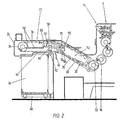
- Two-color sheetfed offset press 2 become paper sheets successively by means of an automated sheet feed 4 from one arranged in a sheet feeder 6 of the printing press 2 Paper stack 8 to a feed drum 10 of a first Transfer printing unit 12 and then through the first printing unit 12 and possibly transported a second printing unit 14 in order to or to print on both sides in one or more colors.
- a sheet delivery 22 of the printing machine 2 From an impression cylinder 16 of the second printing unit 14 take over delivery gripper systems 18 of a chain conveyor 20 a sheet delivery 22 of the printing machine 2, the printed sheets and transport them through a housing 24 of the sheet delivery 22 to a sheet stack 26 on which the sheet then are stacked on top of each other.
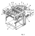
- the chain conveyor 20 is in the essentially two in opposite side Guide rails 28 (Fig. 3) guided parallel chains (not shown), which at regular intervals the gripper systems 18, also referred to as bow grippers are connected.
- the chain conveyor 20 has a lower one Bow conveyor conveyor (leading system) 30 on that of the two sprockets 31 one Delivery drum 32 moved obliquely upwards and then into the Horizontal is deflected before there are two drive sprockets 34 reached at the free end of the sheet delivery 22. His top Empty run (return system) 36 moves from the Sprockets 34 from horizontally towards the printing press 2 before it is turned diagonally down and to the delivery drum 32 is returned.
- Bow conveyor conveyor leading system
- each sheet is in Direction of movement of the conveyor run 30 through sheet baffles 38 non-contact on laterally adjustable guide arm blowers 40 over and via a sheet brake 42 arranged behind it guided and then reaches an arch exit opening 44 on the underside of the horizontal section of the housing 24 of the sheet delivery 22 to the sheet brake 42 transferred and braked sheet With the help of several arranged above the outlet opening 44 Delivery fan 46 down onto the sheet stack 26 blown. This rests on a lifting mechanism 48 that the Stack 26 in sync with the speed of the sheet feed lowers.
- a powder apparatus 50 is located horizontally above it in the space 52 between the conveyor run 30 and the empty run 36 arranged.
- the powder apparatus 52 pollinates the top of the held by the bow grippers 18 of the conveyor run 30 pressurized sheets with a fine powdered starch powder to a sticking together (putting on) of the sheets at the subsequent To prevent stacking.
- the powder apparatus 50 is made essentially from a transverse to the direction of movement of the Chain conveyor 20 through the space 52 extending tube 54, which has several powder outlet slots on its underside having.
- the starch powder is made using a pipe 54 connected blower (not shown) supplied, the Dosage of the size and color intensity of the printed Area is dependent. But not only that printed sheets, but also the chains and the sheet grabs 18 of the chain conveyor 20 dusted with the powder.
- the paper sheets carried by the chain conveyor 20 are in Direction of movement of the conveyor run 30 immediately behind the Powder apparatus 50 deflected from the inclines into the horizontal. This leads to the whip or flag effect, that is to a rocking or Flutter the back edges of the paper sheets 1. This in turn causes the powder emerging from the powder apparatus 50 is whirled up immediately after the exit. This Whirled up powder is caught by the suction of the chain conveyor 20 and by a suction-induced one in the direction of movement of the chain conveyor 20 entrained air flow.
- the Fresh air not contaminated with powder is supplied by a nozzle box 58 which over the powder suction and Air deflection trough 56 in the area of the nozzle box 58 closed upper wall of the housing 24 is inserted and the Fresh air blows down towards the Printing machine running powder-laden air flow interrupt and thus the transport of powder carried in Prevent the direction of the press.
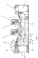
- the powder suction and air deflection tray 56 and the nozzle box 58 are arranged behind the point at which the conveyor run 30 in the horizontal is redirected, with the in the Figures 1 and 2 illustrated embodiment in Direction of movement of the conveyor run 30 before Sheet exit opening 44 and the one above it Display fans 46 are arranged while in the Fig. 3 illustrated embodiment with a shorter Sheet delivery 22 are immediately above.
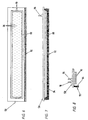
- the suction and air deflection tray 56 essentially from one thin-walled flat housing 62.
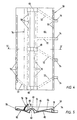
- the housing 62 extends below the side guides of the empty run 36 over the total clear width of the housing 24 of the sheet delivery 22 and forms a continuous partition between a lower, flow path running along the conveyor run 30 and a movement path of the empty run 36 arranged above it. This partition prevents the entire extent Air passes from top to bottom and vice versa.
- the housing 62 has a in the direction of movement Chain conveyor 20 upper housing wall 64 which has been bent several times, so that two shallow troughs 66 are formed by one Elevation 68 arranged between them are separated from one another.
- the upper housing wall 64 is also spaced apart arranged rows of suction slots 70 provided. While adjacent middle rows of suction slots 70 are located at the lowest points of the troughs 66 outer rows in the immediate vicinity of the opposite Arranged outer edges of the housing 62.
- Each of the rows of slots is arranged by a within the housing 62
- Suction channel 72 each connected to a suction port 74, which one of the outer edges are arranged.
- the suction nozzle 74 are each via directional and pressure control valves to control the extracted air quantities and the applied vacuum with connected to a suction fan, which a dust separator with a Centrifuge and a fine filter (not shown) is connected upstream. From the rows of suction slots 70 are the slots 70 on the outer edge on the side of the Powder apparatus 50 most heavily applied with negative pressure.
- the brush 76 is in of the trough 66 which extends from the housing 62 leaving empty strand 36 of the chain conveyor 20 first is swept over.
- the housing 62 also has a lower housing wall 80 which between the two troughs 66 and below the elevation 68 the upper housing wall 64 with a recessed upwards Bulge 82 is provided, the cross section of which is in the form of a reverse U has.
- this bulge 82 encloses the housing wall 80 between the empty strand 36 and the conveyor run 30 arranged transverse drive shaft 60, the top of which carries the housing 62.
- To reduce the Friction between the slow-running drive shaft 60 and the lower housing wall 80 is in the area of Provide bulge 82 with a Teflon coating.
- suction and air deflection tray 56 is supported the drive shaft 60 from, so that it with only a few Fastening screws on opposite side cheeks of the Chain conveyor 20 must be attached to them in place to keep.
- the Air outlet nozzles 86 are arranged in parallel rows, of which the middle one is just above the elevation 68 on the Top of the suction and air deflection tray 56 is.
- An edge 88 adjacent to the flat underside smaller lower part of the nozzle box 58 is chamfered and on its narrower faces with a series of Nozzle openings 90 provided for showering the chains of the Chain conveyor 20 serve.
- the larger top of the Nozzle box 58 is provided with a circumferential shoulder, whose narrow foreheads on the side cheeks of the Chain arm rest.
- On the bottom of the shoulder is a brush 92 is attached, the bristles 94 of which are down extend into the path of the empty run 36.
- the brush 92 also extends over the entire clear width of the Chain boom or the housing 24 and is in Direction of movement of the empty run 36 immediately behind the Brush 76 of the suction and air deflection tray 56 arranged.
- the application of compressed air to the nozzle box 58 with a Pressure between 1.5 and 3.5 bar occurs through two Air supply nozzle 96 on the top of the nozzle box 58, each communicating with a part of the nozzle rows 86.
- the amount of air supplied is such that only a part again through the suction slots 70 of the suction and Air deflector tray 56 can be sucked in while the rest Air in the top of the suction and air deflection tray 56 in Direction of the printing machine is deflected.
- the air is at a relatively low pressure of 1.5 to 2 bar supplied, while the air pressure at a downstream cleaning of the sheet delivery 22 to 3 to 3.5 bar is increased.
- Directional control valves in the to the air supply nozzle Allow 96 leading air supply lines (not shown) a clocked air supply or an optional air supply each one of the two air supply nozzles 96 or both together, i.e. to a part of each of the nozzles 86 or all nozzles 86.
- the air blown down from the nozzle box 58 flows in the sheet grippers 18 and on the chains of the chain conveyor 20 over, and shower this with clean fresh air, whereby adhering powder particles are carried down so that from the empty run 36 no further towards the printing press 2 can be transported.
- Suction slots 70 are formed as a result of the created there Vacuum also from fresh air vortex, at the Bottom of the air also in the opposite direction to Tub 56 flows back to the front and part of the whirled up powder with it, so that this through the Suction slots 70 on the adjacent outer edge of the tub 56 can be suctioned off.
- the Most of the air sucked in is from the suction of the empty run 36 carried along the same in the direction of the printing press 2, while a smaller part behind that which acts as an air switch Air suction pipe 75 down and along the press side of the powder apparatus 50 flows down.
- air can also be in front of the brushes 76, 92 be suctioned off, so that by one arising there Negative pressure a smaller part of that behind the brushes 76, 92 supplied air sucked forward through the brushes 76, 92 becomes.
- the brushes 76, 92 can also be omitted and the air flow running along the empty run 36 alone interrupted by the supply and / or extraction of air.
- the measures described above will in particular prevents powder from being whirled up by the Suction of the chain conveyor 20 entrained and over and over under the empty strand 36 generated air flow within the Housing 24 of the sheet delivery 22 in the direction of the printing press 2 is transported.
- the spread of powder is in the essentially to the area below the powder apparatus 50 and above the printed sheets below limited, which on the one hand significantly reduces powder consumption can be reduced and on the other hand both the Dust pollution in the ambient air as well as inside the Housing is significantly lower.
- both the Dust pollution in the ambient air as well as inside the Housing is significantly lower.
- the fresh air cushion accelerates between the Conveyor strand 30 and the empty strand 36 on that of the printing press 2 facing side of the powder apparatus 50 the oxidative drying of the printing inks due to the constant fresh air supply in them Area.
Claims (33)
- Procédé selon lequel, dans une machine à imprimer (2) comprenant au moins un groupe d'impression (12, 14), des feuilles imprimées sont transportées au moyen d'un dispositif de transport de feuilles (20) à travers un poste de sortie de feuilles (22), au-dessus d'une pile de réception de feuilles (26), et sont, à cette occasion, saupoudrées d'une poudre, et selon lequel l'écoulement d'air chargé de poudre se déplaçant dans un carter (24) du poste de sortie de feuilles (22) dans la direction d'avance d'un brin vide (36) du dispositif de transport de feuilles (20), vers le groupe d'impression (12, 14), est entouré de toutes part et interrompu au niveau d'au moins une zone d'interruption entre l'extrémité libre du poste de sortie de feuilles (22) et le groupe d'impression (12, 14), à l'aide de dispositifs (56, 58, 76, 92) englobant des moyens mécaniques et/ou pneumatiques (58, 76, 92) en commun avec les parois latérales du carter, le trajet d'écoulement de l'écoulement d'air chargé en poudre étant sensiblement totalement obturé sur l'ensemble de la largeur de passage libre du carter (24) du poste de sortie de feuilles (22), à l'aide des dispositifs (56, 58, 76, 92) englobant des moyens mécaniques et/ou pneumatiques (58, 76, 92), de sorte que l'on empêche ainsi un transport de poudre en excédent entraínée dans l'écoulement d'air en direction du groupe d'impression (12, 14) et une propagation incontrôlée de la poudre, et l'écoulement d'air étant interrompu au-dessus d'une partie (56) des dispositifs (56, 58, 76, 92), qui agit en tant que paroi séparatrice, et est disposée entre le brin vide (36) et un brin de transport (30) du dispositif de transport de feuilles (20).
- Procédé selon la revendication 1, caractérisé en ce que l'écoulement d'air est interrompu dans une zone partielle horizontale, supérieure, du poste de sortie de feuilles (22).
- Procédé selon la revendication 1 ou 2, caractérisé en ce que l'écoulement d'air est interrompu sensiblement au-dessus d'un arbre d'entraínement (60) d'un mécanisme de levée (48) pour la pile de réception de feuilles (26).
- Procédé selon l'une des revendications 1 à 3, caractérisé en ce que pour interrompre l'écoulement d'air, de l'air non chargé en poudre est amené dans le carter de manière à balayer le brin vide (36) transversalement à son mouvement de déplacement.
- Procédé selon la revendication 4, caractérisé en ce que l'air est amené par le haut dans le carter.
- Procédé selon la revendication 4 ou 5, caractérisé en ce que l'air est amené, en se référant au sens du mouvement du brin vide (36), derrière un agencement de brosse (76, 92) qui obture au moins partiellement le trajet d'écoulement.
- Procédé selon l'une des revendications 4 à 6, caractérisé en ce qu'au moins une partie de l'air amené est déviée en direction du groupe d'impression (12, 14).
- Procédé selon la revendication 7, caractérisé en ce qu'au moins une partie de l'air dévié est envoyée en direction du groupe d'impression (12, 14) en passant au-dessus un dispositif de saupoudrage (50) saupoudrant les feuilles avec de la poudre.
- Procédé selon l'une des revendications 1 à 8, caractérisé en ce que pour interrompre l'écoulement d'air, de l'air chargé en poudre est évacué en étant aspiré dans la région de la zone d'interruption.
- Procédé selon la revendication 9, caractérisé en ce qu'au moins une partie de l'air amené dans le carter, est évacuée en étant aspirée, après un passage à travers le brin vide (36).
- Procédé selon la revendication 10, caractérisé en ce que l'air est évacué en étant aspiré sensiblement à l'opposé de la zone de laquelle il est amené dans le carter.
- Procédé selon l'une des revendications 9 à 11, caractérisé en ce que l'air chargé de poudre est évacué en étant aspiré dans l'environnement d'un agencement de brosse (76, 92), qui obture au moins partiellement ou sensiblement totalement le trajet d'écoulement de l'air chargé de poudre.
- Procédé selon l'une des revendications 1 à 12, caractérisé en ce que dans la région de la zone d'interruption et/ou derrière en se référant à la direction de mouvement du brin vide (36), de l'air supplémentaire est aspiré de l'extérieur dans le carter (24), à travers une ouverture d'air (95).
- Poste de sortie de feuilles (22) destiné à une machine à imprimer des feuilles (2) englobant au moins un groupe d'impression (12, 14), comprenant un carter (24), un dispositif de transport de feuilles (20) placé dans le carter (24) et destiné au transport de feuilles imprimées au-dessus d'une pile de réception de feuilles (26), un dispositif de saupoudrage (50) destiné à saupoudrer les feuilles imprimées avec une poudre, ainsi que des dispositifs (58, 56, 76, 92) qui, en commun avec les parois latérales du carter (24), et au niveau d'au moins une zone d'interruption entre l'extrémité libre du poste de sortie de feuilles (22) et le groupe d'impression (12, 14), entourent de toutes part et interrompent l'écoulement d'air chargé de poudre se déplaçant dans la direction d'avance d'un brin vide (36) du dispositif de transport de feuilles (20), vers le groupe d'impression (12, 14), les dispositifs (58, 56, 76, 92) avec des moyens pneumatiques et/ou mécaniques, obturant sensiblement totalement le trajet d'écoulement de l'écoulement d'air chargé de poudre, sur la totalité de la largeur de passage libre du carter (24) du poste de sortie de feuilles (22), en vue d'empêcher le passage de l'air chargé de poudre et ainsi un transport de poudre entraínée en direction du groupe d'impression (12, 14), et la zone d'interruption se situant au-dessus d'une partie (56) des dispositifs (58, 56, 76, 92), qui agit en tant que paroi séparatrice, et est disposée entre le brin vide (36) et un brin de transport (30) du dispositif de transport de feuilles (20).
- Poste de sortie de feuilles selon la revendication 14, caractérisé en ce que les dispositifs (58, 56, 76, 92) comprennent au moins un dispositif d'amenée d'air (58), qui amène de l'air non chargé de poudre dans le carter, de façon à que cet air balaye le brin vide (36) transversalement à sa direction de mouvement.
- Poste de sortie de feuilles selon la revendication 14 ou 15, caractérisé en ce que la partie (56) des dispositifs (58, 56, 76, 92), qui fait office de paroi séparatrice, comprend au moins un dispositif d'aspiration (56) qui évacue de l'air par aspiration dans la région de la zone d'interruption.
- Poste de sortie de feuilles selon la revendication 16, caractérisé en ce que le dispositif d'aspiration (56) est sensiblement disposé en regard du dispositif d'amenée d'air (58) et évacue par aspiration au moins une partie de l'air amené dans le carter par le dispositif d'amenée d'air (58), après son passage à travers le brin vide (36).
- Poste de sortie de feuilles selon la revendication 16 ou 17, caractérisé en ce que le dispositif d'aspiration (56) et le dispositif d'amenée d'air (58) sont agencés l'un au-dessus de l'autre.
- Poste de sortie de feuilles selon l'une des revendications 16 à 18, caractérisé en ce que le dispositif d'aspiration (56) est disposé en-dessous du brin vide (36) et présente sur son côté supérieur dirigé vers le brin vide (36), au moins une ouverture d'aspiration (70).
- Poste de sortie de feuilles selon l'une des revendications 14 à 19, caractérisé en ce que les dispositifs (76, 92, 58, 56) comprennent des moyens mécaniques se présentant sous la forme d'un agencement de brosse (76, 92).
- Poste de sortie de feuilles selon la revendication 20, caractérisé en ce que le dispositif d'amenée d'air (58) est disposé derrière l'agencement de brosse (76, 92) en se référant à la direction de mouvement du brin vide (36).
- Poste de sortie de feuilles selon l'une des revendications 20 ou 21, caractérisé en ce que le dispositif d'aspiration (56) est disposé dans l'environnement de l'agencement de brosse (76, 92).
- Poste de sortie de feuilles selon l'une des revendications 20 à 22, caractérisé en ce que l'agencement de brosse comprend au moins deux brosses dont les poils ou fibres se chevauchent ou se touchent dans le trajet de mouvement du brin vide (36).
- Poste de sortie de feuilles selon l'une des revendications 14 à 23, caractérisé en ce que dans la région de la zone d'interruption et/ou derrière en se référant à la direction de mouvement du brin vide (36), est disposée au moins une ouverture d'air (95), qui permet d'aspirer de l'air supplémentaire non chargé en poudre, vers l'intérieur du carter (24).
- Poste de sortie de feuilles selon la revendication 24, caractérisé en ce que l'ouverture d'air (95) est disposée sur le côté supérieur du carter (24), au-dessus du brin vide (36).
- Poste de sortie de feuilles selon l'une des revendications 14 à 25, caractérisé en ce qu'au moins une partie des dispositifs (76, 92, 58, 56) est montée derrière le dispositif de saupoudrage (50) en se référant à la direction de mouvement du brin de transport (30) du dispositif de transport des feuilles (20).
- Poste de sortie de feuilles selon l'une des revendications 14 à 26, caractérisé en ce qu'au moins une partie des dispositifs (76, 92, 58, 56) est montée dans un tronçon partiel horizontal du poste de sortie de feuilles (22).
- Poste de sortie de feuilles selon l'une des revendications 14 à 27, caractérisé en ce qu'au moins une partie des dispositifs (76, 92, 58, 56) est montée au-dessus d'un dispositif à soufflante ou buses d'air (46) soufflant la feuille imprimée vers le bas sur la pile de réception de feuilles (26).
- Poste de sortie de feuilles selon l'une des revendications 14 à 28, caractérisé en ce qu'au moins une partie des dispositifs (76, 92, 58, 56) est montée, en se référant à la direction de mouvement du brin de transport (30), derrière une zone au niveau de laquelle le brin de transport (30) est dévié à l'horizontale.
- Poste de sortie de feuilles selon l'une des revendications 14 à 29, caractérisé en ce qu'au moins une partie des dispositifs (76, 92, 58, 56) est montée au-dessus et respectivement devant et derrière un arbre d'entraínement (60) d'un mécanisme de levée (48) pour la pile de réception de feuilles (26), qui traverse un espace intermédiaire (52) entre le brin vide (36) et le brin de transport (30).
- Poste de sortie de feuilles selon l'une des revendications 14 à 29, caractérisé en ce que la partie (56) des dispositifs (76, 92, 58, 56) agissant en tant que paroi séparatrice, est réalisée en tant que dispositif déflecteur ou déviateur, qui dévie au moins une partie de l'air amené, en direction du groupe d'impression (12, 14).
- Machine à imprimer des feuilles, caractérisée par un poste de sortie de feuilles selon l'une des revendications 14 à 31.
- Machine à imprimer des feuilles selon la revendication 32, caractérisée par des dispositifs pour nettoyer l'air amené et/ou évacué par aspiration.
Applications Claiming Priority (5)
| Application Number | Priority Date | Filing Date | Title |
|---|---|---|---|
| DE19801949 | 1998-01-20 | ||
| DE19801949 | 1998-01-20 | ||
| DE19852714 | 1998-11-16 | ||
| DE19852714 | 1998-11-16 | ||
| PCT/EP1999/000271 WO1999037484A1 (fr) | 1998-01-20 | 1999-01-19 | Procede et dispositif pour empecher une propagation incontrolee de poudre dans une machine a imprimer |
Publications (2)
| Publication Number | Publication Date |
|---|---|
| EP1049584A1 EP1049584A1 (fr) | 2000-11-08 |
| EP1049584B1 true EP1049584B1 (fr) | 2003-01-15 |
Family
ID=26043223
Family Applications (1)
| Application Number | Title | Priority Date | Filing Date |
|---|---|---|---|
| EP99908798A Expired - Lifetime EP1049584B1 (fr) | 1998-01-20 | 1999-01-19 | Procede et dispositif pour empecher une propagation incontrolee de poudre dans une machine a imprimer |
Country Status (5)
| Country | Link |
|---|---|
| US (1) | US6802256B1 (fr) |
| EP (1) | EP1049584B1 (fr) |
| JP (1) | JP4436564B2 (fr) |
| DE (2) | DE19859246A1 (fr) |
| WO (1) | WO1999037484A1 (fr) |
Families Citing this family (10)
| Publication number | Priority date | Publication date | Assignee | Title |
|---|---|---|---|---|
| DE19859246A1 (de) * | 1998-01-20 | 1999-07-22 | Koch Hans Peter | Bogenoffsetdruckverfahren und Bogenoffsetdruckmaschine |
| DE10161269B4 (de) * | 2001-12-13 | 2005-03-17 | Koenig & Bauer Ag | Ausleger einer Bogenrotationsdruckmaschine |
| DE10161267B4 (de) * | 2001-12-13 | 2007-08-09 | Koenig & Bauer Aktiengesellschaft | Einrichtung zur Puder- und Warmluftabsaugung im Ausleger einer Bogenrotationsdruckmaschine |
| JP4096624B2 (ja) * | 2002-05-23 | 2008-06-04 | コニカミノルタホールディングス株式会社 | 用紙スタッカー |
| DE10227242A1 (de) * | 2002-06-19 | 2004-02-05 | Koenig & Bauer Ag | Anordnung zum Pudern von Flächengebilden in einer Druckmaschine |
| DE10316472A1 (de) * | 2003-04-09 | 2004-10-28 | Heidelberger Druckmaschinen Ag | Verfahren zum Trocknen einer Druckfarbe auf einem Bedruckstoff in einer Druckmaschine und Druckmaschine |
| JP5595823B2 (ja) * | 2010-07-30 | 2014-09-24 | 富士フイルム株式会社 | 画像形成方法及び画像形成装置 |
| JP5202663B2 (ja) | 2011-02-21 | 2013-06-05 | 富士フイルム株式会社 | マット剤塗布装置およびインクジェット記録装置 |
| JP7139591B2 (ja) | 2017-10-05 | 2022-09-21 | セイコーエプソン株式会社 | 液体噴射装置、および液体噴射装置のメンテナンス方法 |
| JP2022112986A (ja) * | 2021-01-22 | 2022-08-03 | 株式会社リコー | シート積載装置、印刷装置 |
Family Cites Families (57)
| Publication number | Priority date | Publication date | Assignee | Title |
|---|---|---|---|---|
| US1360753A (en) * | 1918-11-25 | 1920-11-30 | Johnson Perfection Burner Comp | Burner |
| US1944946A (en) * | 1931-08-11 | 1934-01-30 | Anton G E Nordquist | Static eliminator and ink drier for printing presses |
| GB1052362A (fr) * | 1964-08-28 | |||
| US3399872A (en) * | 1967-05-18 | 1968-09-03 | Henry R. Dickerson | Jet manifold ink oxidizer |
| SE319969B (fr) * | 1969-02-14 | 1970-01-26 | Svenska Flaektfabriken Ab | |
| US3717408A (en) * | 1970-08-19 | 1973-02-20 | Gaf Corp | Flash flat-bed wet copier |
| US3677224A (en) * | 1970-09-18 | 1972-07-18 | Electroprint Inc | Toner charging and feeding machine |
| DE2148757B1 (de) * | 1971-09-30 | 1972-09-07 | Roland Offsetmaschf | Reinigungsgeraet fuer eine Bogenauslegevorrichtung |
| US3881653A (en) * | 1971-12-22 | 1975-05-06 | Vitek Research Corp | Powder deposition system |
| US3915737A (en) * | 1973-11-21 | 1975-10-28 | Gen Tire & Rubber Co | Method and apparatus for removing foreign particles from a calendered sheet by neutralization of static on the sheet |
| US3882818A (en) * | 1973-12-17 | 1975-05-13 | Electro Sprayer Systems Inc | Powder collector construction |
| US4040616A (en) * | 1976-01-14 | 1977-08-09 | Xerox Corporation | Sheet turn around/inverter |
| US4212266A (en) * | 1978-12-21 | 1980-07-15 | The Continental Group, Inc. | Catcher and return device for oversprayed powder |
| US4207833A (en) * | 1978-12-28 | 1980-06-17 | Protectaire Systems Co. | Protected conveyor system |
| US4514779A (en) * | 1983-06-09 | 1985-04-30 | Therm-O-Type Corporation | Methods and apparatus for neutralizing a static electrical charge on powder particles |
| US4611989A (en) * | 1985-08-28 | 1986-09-16 | Erik Kersting | Horizontally extending curing devices |
| EP0230147A3 (fr) * | 1985-12-31 | 1988-01-07 | Protectaire Systems Company | Caisson à rideau d'air pour convoyeur |
| US4946718A (en) * | 1985-12-31 | 1990-08-07 | Protectaire Systems Co. | Air curtain housing for conveyor mechanism |
| US4902315A (en) * | 1987-11-30 | 1990-02-20 | Spicer R Christopher | Negative pressure asbestos removal with localized make-up air |
| US4888200A (en) * | 1988-04-21 | 1989-12-19 | W. R. Grace & Co.,-Conn. | Process and machine for electrostatic coating |
| JPH02150177A (ja) | 1988-12-01 | 1990-06-08 | Matsushita Electric Ind Co Ltd | ビデオカメラ装置 |
| US4960200A (en) * | 1989-08-04 | 1990-10-02 | Mepaco, Inc. | Conveyer belt cleaning and sanitizing apparatus |
| FR2656571B1 (fr) * | 1989-12-29 | 1992-05-07 | Oce Graphics France | Dispositif pour le guidage secondaire d'un support d'impression sur une machine a dessiner. |
| US5245925A (en) * | 1990-04-19 | 1993-09-21 | Ryco Graphic Manufacturing Inc. | Dry brush cleaning apparatus and method for cleaning printing press blanket cylinders |
| JPH0733080B2 (ja) * | 1990-06-08 | 1995-04-12 | 板坂 征夫 | 印刷機の集麈装置 |
| US5086700A (en) * | 1990-09-10 | 1992-02-11 | Eduard Van Den Berg | Drying/curing apparatus for printing presses |
| DE9115032U1 (fr) * | 1991-12-04 | 1992-01-16 | Heidelberger Druckmaschinen Ag, 6900 Heidelberg, De | |
| DE4207118C2 (de) * | 1992-03-06 | 2001-05-10 | Hans G Platsch | Bestäubungsgerät |
| US5293985A (en) * | 1992-05-11 | 1994-03-15 | Alvarez Rick E | Cleaning device for dry cleaning conveyor |
| US5484061A (en) * | 1992-08-04 | 1996-01-16 | Advanced Electrostatic Technologies, Inc. | Electrostatic sieving apparatus |
| WO1994007782A1 (fr) * | 1992-10-05 | 1994-04-14 | Frigoscandia Equipment Aktiebolag | Appareil de lavage de bande transporteuse |
| US5265536A (en) * | 1993-01-11 | 1993-11-30 | Millard James S | System for collecting airborne powder, mists, and fumes |
| US5743958A (en) * | 1993-05-25 | 1998-04-28 | Nordson Corporation | Vehicle powder coating system |
| US5537925A (en) * | 1993-09-03 | 1996-07-23 | Howard W. DeMoore | Infra-red forced air dryer and extractor |
| US5397394A (en) * | 1993-09-09 | 1995-03-14 | The Fishing Group | Powder coating booth |
| DE19549589B4 (de) * | 1995-02-01 | 2005-11-17 | Heidelberger Druckmaschinen Ag | Bogenleiteinrichtung für Druckmaschinen |
| US5540152A (en) * | 1995-04-10 | 1996-07-30 | Demoore; Howard W. | Delivery conveyor with control window ventilation and extraction system |
| US5634401A (en) * | 1995-04-25 | 1997-06-03 | Electric City Printing Company | Printing press powder removal system |
| JPH08295009A (ja) * | 1995-04-27 | 1996-11-12 | Mitsubishi Heavy Ind Ltd | フレキソ印刷機 |
| JPH0957945A (ja) * | 1995-08-25 | 1997-03-04 | Kinki Seiko Kk | 印刷機用集塵装置 |
| US5713285A (en) * | 1995-10-06 | 1998-02-03 | Oxy-Dry Corporation | Powder spray systems and methods for their use |
| US5758580A (en) * | 1996-03-13 | 1998-06-02 | Heidelberger Druckmaschinen Ag | Printing unit using various ink types |
| US5671838A (en) * | 1996-04-02 | 1997-09-30 | Bowman; John H. | Apparatus for cleaning of conveyors |
| US5746302A (en) * | 1996-04-02 | 1998-05-05 | Bowman; John H. | Apparatus for cleaning conveyors |
| US5649616A (en) * | 1996-04-11 | 1997-07-22 | Stecklow; Richard L. | Conveyor chain cleaning apparatus |
| DE19617194C2 (de) * | 1996-04-29 | 2000-09-14 | Ltg Lufttechnische Gmbh | Luftabsaugvorrichtung für Druckmaschinen |
| DE19648227A1 (de) * | 1996-11-21 | 1998-05-28 | Hans Georg Platsch | Verfahren und Vorrichtung zum Bestäuben von Produkten, insbesondere Druckprodukten |
| US6170427B1 (en) * | 1997-01-15 | 2001-01-09 | Optimum Air Corporation | Radiation curing system |
| US5782183A (en) * | 1997-03-07 | 1998-07-21 | Ward Holding Company, Inc. | Pressurized machine for processing blanks |
| JP3568086B2 (ja) * | 1997-03-28 | 2004-09-22 | 株式会社前川製作所 | 低温食品加工装置 |
| US5966836A (en) * | 1997-04-11 | 1999-10-19 | Howard W. DeMoore | Infrared heating apparatus and method for a printing press |
| US6220693B1 (en) * | 1997-09-29 | 2001-04-24 | Colorspan Corporation | Overspray adaptation method and apparatus for an ink jet print engine |
| DE19859246A1 (de) * | 1998-01-20 | 1999-07-22 | Koch Hans Peter | Bogenoffsetdruckverfahren und Bogenoffsetdruckmaschine |
| DE19901245A1 (de) * | 1998-02-17 | 1999-08-19 | Heidelberger Druckmasch Ag | Vorrichtung zum Pudern bedruckter Bogen |
| US6182567B1 (en) * | 1998-03-24 | 2001-02-06 | Heidelberger Druckmaschinen Aktiengesellschaft | Printing press with an actuator |
| IT1301697B1 (it) * | 1998-06-12 | 2000-07-07 | Cml Handling Technology S P A | Apparecchiatura per la pulitura dei tappetini rotanti in macchinesmistatrici e macchina smistatrice dotata di detta apperecchiatura. |
| DE10007249A1 (de) * | 1999-03-29 | 2000-10-05 | Heidelberger Druckmasch Ag | Ausleger für eine Bogen verarbeitende Druckmaschine |
-
1998
- 1998-12-22 DE DE19859246A patent/DE19859246A1/de not_active Withdrawn
-
1999
- 1999-01-19 JP JP2000528433A patent/JP4436564B2/ja not_active Expired - Fee Related
- 1999-01-19 EP EP99908798A patent/EP1049584B1/fr not_active Expired - Lifetime
- 1999-01-19 DE DE59904038T patent/DE59904038D1/de not_active Expired - Lifetime
- 1999-01-19 WO PCT/EP1999/000271 patent/WO1999037484A1/fr active IP Right Grant
-
2000
- 2000-07-20 US US09/619,975 patent/US6802256B1/en not_active Expired - Fee Related
Also Published As
| Publication number | Publication date |
|---|---|
| JP2002500974A (ja) | 2002-01-15 |
| DE59904038D1 (de) | 2003-02-20 |
| DE19859246A1 (de) | 1999-07-22 |
| WO1999037484A1 (fr) | 1999-07-29 |
| US6802256B1 (en) | 2004-10-12 |
| EP1049584A1 (fr) | 2000-11-08 |
| JP4436564B2 (ja) | 2010-03-24 |
Similar Documents
| Publication | Publication Date | Title |
|---|---|---|
| DE19733691C2 (de) | Bogen verarbeitende Rotationsdruckmaschine | |
| EP1049584B1 (fr) | Procede et dispositif pour empecher une propagation incontrolee de poudre dans une machine a imprimer | |
| DE19901670C5 (de) | Verfahren und Vorrichtung zum Sauberhalten und/oder Reinigen einer Bogenauslage einer Bogenoffsetdruckmaschine | |
| CH397727A (de) | Blattabgabemechanismus für eine Druckerpresse | |
| EP1091855B1 (fr) | Procede offset a feuilles et presse offset a feuilles | |
| DE19643987C1 (de) | Bestäubungseinrichtung | |
| DE19826083B4 (de) | Puderabsaugung in Auslegern von Bogenrotationsdruckmaschinen | |
| EP1066160B1 (fr) | Procede et machine d'impression offset | |
| EP0947321B1 (fr) | Poudreur dans une machine d'impression | |
| DE10304617B4 (de) | Bogenförderer für eine Bogen verarbeitende Maschine | |
| EP1834912B1 (fr) | Machine de traitement des feuilles avec un dispositif de guidage par air comprimé pour des feuilles | |
| DE19631175C1 (de) | Vorrichtung zur Bogenzufuhr zu einer Druckmaschine | |
| DE19647259A1 (de) | Verfahren und Vorrichtung zur Reinigung von Transportmitteln | |
| DE10161269B4 (de) | Ausleger einer Bogenrotationsdruckmaschine | |
| DE19643747A1 (de) | Einrichtung zur Applikation eines Trennmediums auf flächige Produkte | |
| DE10161267B4 (de) | Einrichtung zur Puder- und Warmluftabsaugung im Ausleger einer Bogenrotationsdruckmaschine | |
| EP0945268A1 (fr) | Poudreur dans une machine à imprimer | |
| DE10207865A1 (de) | Ausleger für eine flächige Bedruckstoffe verarbeitende Maschine | |
| DE10144165B4 (de) | Vorrichtung zur Bogenführung | |
| AT510483A2 (de) | Einrichtung zur absaugung von puderresten in druckmaschinen |
Legal Events
| Date | Code | Title | Description |
|---|---|---|---|
| PUAI | Public reference made under article 153(3) epc to a published international application that has entered the european phase |
Free format text: ORIGINAL CODE: 0009012 |
|
| 17P | Request for examination filed |
Effective date: 20000630 |
|
| AK | Designated contracting states |
Kind code of ref document: A1 Designated state(s): BE CH DE FR GB LI NL Kind code of ref document: A1 Designated state(s): BE CH DE FR GB IT LI NL |
|
| 17Q | First examination report despatched |
Effective date: 20010312 |
|
| GRAG | Despatch of communication of intention to grant |
Free format text: ORIGINAL CODE: EPIDOS AGRA |
|
| RBV | Designated contracting states (corrected) |
Designated state(s): BE CH DE FR GB IT LI NL |
|
| GRAG | Despatch of communication of intention to grant |
Free format text: ORIGINAL CODE: EPIDOS AGRA |
|
| GRAH | Despatch of communication of intention to grant a patent |
Free format text: ORIGINAL CODE: EPIDOS IGRA |
|
| GRAH | Despatch of communication of intention to grant a patent |
Free format text: ORIGINAL CODE: EPIDOS IGRA |
|
| GRAA | (expected) grant |
Free format text: ORIGINAL CODE: 0009210 |
|
| AK | Designated contracting states |
Kind code of ref document: B1 Designated state(s): BE CH DE FR GB IT LI NL |
|
| REG | Reference to a national code |
Ref country code: GB Ref legal event code: FG4D Free format text: NOT ENGLISH Ref country code: CH Ref legal event code: EP |
|
| REF | Corresponds to: |
Ref document number: 59904038 Country of ref document: DE Date of ref document: 20030220 Kind code of ref document: P |
|
| PGFP | Annual fee paid to national office [announced via postgrant information from national office to epo] |
Ref country code: BE Payment date: 20030307 Year of fee payment: 5 |
|
| PGFP | Annual fee paid to national office [announced via postgrant information from national office to epo] |
Ref country code: NL Payment date: 20030311 Year of fee payment: 5 |
|
| GBT | Gb: translation of ep patent filed (gb section 77(6)(a)/1977) |
Effective date: 20030315 |
|
| ET | Fr: translation filed | ||
| PLBE | No opposition filed within time limit |
Free format text: ORIGINAL CODE: 0009261 |
|
| STAA | Information on the status of an ep patent application or granted ep patent |
Free format text: STATUS: NO OPPOSITION FILED WITHIN TIME LIMIT |
|
| 26N | No opposition filed |
Effective date: 20031016 |
|
| PG25 | Lapsed in a contracting state [announced via postgrant information from national office to epo] |
Ref country code: BE Free format text: LAPSE BECAUSE OF NON-PAYMENT OF DUE FEES Effective date: 20040131 |
|
| BERE | Be: lapsed |
Owner name: *KOCH HANS-PETER Effective date: 20040131 Owner name: *HEIDELBERGER DRUCKMASCHINEN A.G. Effective date: 20040131 |
|
| PG25 | Lapsed in a contracting state [announced via postgrant information from national office to epo] |
Ref country code: NL Free format text: LAPSE BECAUSE OF NON-PAYMENT OF DUE FEES Effective date: 20040801 |
|
| NLV4 | Nl: lapsed or anulled due to non-payment of the annual fee |
Effective date: 20040801 |
|
| PG25 | Lapsed in a contracting state [announced via postgrant information from national office to epo] |
Ref country code: IT Free format text: LAPSE BECAUSE OF NON-PAYMENT OF DUE FEES;WARNING: LAPSES OF ITALIAN PATENTS WITH EFFECTIVE DATE BEFORE 2007 MAY HAVE OCCURRED AT ANY TIME BEFORE 2007. THE CORRECT EFFECTIVE DATE MAY BE DIFFERENT FROM THE ONE RECORDED. Effective date: 20050119 |
|
| PGRI | Patent reinstated in contracting state [announced from national office to epo] |
Ref country code: IT Effective date: 20091201 |
|
| REG | Reference to a national code |
Ref country code: FR Ref legal event code: PLFP Year of fee payment: 17 |
|
| PGFP | Annual fee paid to national office [announced via postgrant information from national office to epo] |
Ref country code: CH Payment date: 20150122 Year of fee payment: 17 Ref country code: IT Payment date: 20141224 Year of fee payment: 17 |
|
| PGFP | Annual fee paid to national office [announced via postgrant information from national office to epo] |
Ref country code: GB Payment date: 20150122 Year of fee payment: 17 Ref country code: FR Payment date: 20150119 Year of fee payment: 17 |
|
| REG | Reference to a national code |
Ref country code: CH Ref legal event code: PL |
|
| GBPC | Gb: european patent ceased through non-payment of renewal fee |
Effective date: 20160119 |
|
| REG | Reference to a national code |
Ref country code: FR Ref legal event code: ST Effective date: 20160930 |
|
| PG25 | Lapsed in a contracting state [announced via postgrant information from national office to epo] |
Ref country code: LI Free format text: LAPSE BECAUSE OF NON-PAYMENT OF DUE FEES Effective date: 20160131 Ref country code: CH Free format text: LAPSE BECAUSE OF NON-PAYMENT OF DUE FEES Effective date: 20160131 Ref country code: GB Free format text: LAPSE BECAUSE OF NON-PAYMENT OF DUE FEES Effective date: 20160119 |
|
| PG25 | Lapsed in a contracting state [announced via postgrant information from national office to epo] |
Ref country code: FR Free format text: LAPSE BECAUSE OF NON-PAYMENT OF DUE FEES Effective date: 20160201 |
|
| PG25 | Lapsed in a contracting state [announced via postgrant information from national office to epo] |
Ref country code: IT Free format text: LAPSE BECAUSE OF NON-PAYMENT OF DUE FEES Effective date: 20160119 |
|
| PGFP | Annual fee paid to national office [announced via postgrant information from national office to epo] |
Ref country code: DE Payment date: 20180131 Year of fee payment: 20 |
|
| REG | Reference to a national code |
Ref country code: DE Ref legal event code: R071 Ref document number: 59904038 Country of ref document: DE |