EP1049584B1 - Method and device for preventing an uncontrolled powder dispersion in a printing machine - Google Patents
Method and device for preventing an uncontrolled powder dispersion in a printing machine Download PDFInfo
- Publication number
- EP1049584B1 EP1049584B1 EP99908798A EP99908798A EP1049584B1 EP 1049584 B1 EP1049584 B1 EP 1049584B1 EP 99908798 A EP99908798 A EP 99908798A EP 99908798 A EP99908798 A EP 99908798A EP 1049584 B1 EP1049584 B1 EP 1049584B1
- Authority
- EP
- European Patent Office
- Prior art keywords
- air
- powder
- sheet
- sheet delivery
- housing
- Prior art date
- Legal status (The legal status is an assumption and is not a legal conclusion. Google has not performed a legal analysis and makes no representation as to the accuracy of the status listed.)
- Expired - Lifetime
Links
Images
Classifications
-
- B—PERFORMING OPERATIONS; TRANSPORTING
- B41—PRINTING; LINING MACHINES; TYPEWRITERS; STAMPS
- B41F—PRINTING MACHINES OR PRESSES
- B41F23/00—Devices for treating the surfaces of sheets, webs, or other articles in connection with printing
- B41F23/04—Devices for treating the surfaces of sheets, webs, or other articles in connection with printing by heat drying, by cooling, by applying powders
- B41F23/044—Drying sheets, e.g. between two printing stations
- B41F23/0443—Drying sheets, e.g. between two printing stations after printing
-
- B—PERFORMING OPERATIONS; TRANSPORTING
- B41—PRINTING; LINING MACHINES; TYPEWRITERS; STAMPS
- B41F—PRINTING MACHINES OR PRESSES
- B41F23/00—Devices for treating the surfaces of sheets, webs, or other articles in connection with printing
- B41F23/04—Devices for treating the surfaces of sheets, webs, or other articles in connection with printing by heat drying, by cooling, by applying powders
- B41F23/06—Powdering devices, e.g. for preventing set-off
-
- B—PERFORMING OPERATIONS; TRANSPORTING
- B65—CONVEYING; PACKING; STORING; HANDLING THIN OR FILAMENTARY MATERIAL
- B65H—HANDLING THIN OR FILAMENTARY MATERIAL, e.g. SHEETS, WEBS, CABLES
- B65H29/00—Delivering or advancing articles from machines; Advancing articles to or into piles
- B65H29/24—Delivering or advancing articles from machines; Advancing articles to or into piles by air blast or suction apparatus
- B65H29/245—Air blast devices
- B65H29/246—Air blast devices acting on stacking devices
- B65H29/247—Air blast devices acting on stacking devices blowing on upperside of the sheet
Definitions
- the invention relates to a method and an apparatus for Prevent an uncontrolled spread of powder in one Press.
- the invention relates in particular to a Process in which sheets printed in a sheet-fed printing machine by means of a sheet conveyor through a sheet delivery conveyed through a stack of sheets and with one Powder are dusted and one is uncontrolled Spread of excess powder is prevented, as well a device for preventing an uncontrolled Spreading powder in a sheet delivery case a sheet printing machine that a sheet conveyor for Transport of printed sheets via a sheet stack and a dusting device for dusting the printed Powder surrounds bow.
- the invention relates above also a sheet delivery for a sheet printing machine and a Sheet printing machine with such a device.
- a paper or chain conveyor Sheet delivery i.e. a chain conveyor with two parallel, connected by delivery gripper systems or sheet grippers Chains included and within a the sheet delivery and enclosing the printing units of the printing press housing transported a stack of sheets on which she then are stacked on top of each other. Since the printing ink at The sheets are not yet completely stacked on top of one another is dried at most on the market located sheetfed offset presses at least one Surface of each sheet before placing it on the stack with powdered on the printed areas of the Sheets of paper stick and a deposit, i.e.
- a sticking together the sheet of paper in the sheet stack prevents.
- Be as powder usually fine powdered potato starch or others powdered starch products used.
- To apply the Powder serves a so-called powder device or another Pollination facility, usually in a space between the leading leading the sheets Conveyor strand and the returning empty strand of the chain conveyor is arranged and the on the lower conveyor run of the Chain conveyor transported sheets from above with dusted the powder.
- High-speed sheetfed offset presses for printing high Requirements such as those under the label Heidelberg Speedmaster from Heidelberger Druckmaschinen AG sheetfed offset presses are usually sold with a high-stack sheet delivery to stack more sheets to be able to. With such sheet displays, this extends Chain conveyor conveyor run first diagonally upwards and is then redirected into the horizontal to the printed Sheets horizontally before releasing them above the sheet filing stack align.
- the pollination facility is common there just before the upper end of the sloping section of the Funding runs in the space between this and the empty run arranged of the chain conveyor.
- a sheet delivery is a Sheet printing machine disclosed in the housing near the Powder dusting device above the conveyor belt devices are provided to suck off excess powder and thus to prevent its uncontrolled spread.
- Such Devices suck a large part of the powder applied immediately, which often has the consequence that the Operating personnel increases the powder supply and so much more Powder is consumed.
- the problem of powder spread an air suction inside the housing, however unsolved.
- a sheet delivery is a Printing machine disclosed in the along an upper horizontal section of the empty run of a sheet conveyor a cleaning device is provided which has a housing, several brushes arranged in the housing and one Suction device includes the brushes from the Vacuum chains and gripper systems of cleaned powder.
- the cleaning device described is still suitable to transport powder-laden air in the direction to prevent the printing press, since both between the Housing of the cleaning device and the adjacent walls the sheet delivery as well as inside the case on both Wide open flow cross-sections on the sides of the brushes are present that have a passage of powdered Allow air along the movement path of the empty run.
- the invention is based on the object a method and a retrofittable and / or Factory assembled device of the type mentioned To provide a during printing Reduction of dust pollution in the vicinity of the Printing machine enables and the formation of powder deposits largely prevented within the housing.
- the invention provides that everyone along the movement path of the empty strand Existing flow path through which powder-contaminated air from the free end of the sheet delivery can flow to the printing press, at least one place between the free end of the Delivery and the printing press is blocked to allow the Formation of a running in the direction of the printing press Air flow and thus a transport of powder in it To prevent air flow to the press. It is for that required the entire free at the point of interruption Flow cross-section between an upper wall of the housing, the two side walls of the housing and one in the space arranged between the empty strand and the conveyor strand Partition or the like essentially completely block so that a passage of powdered air through this section of the flow path almost completely is prevented.
- the air flow is as close as possible to the free end of the Sheet delivery interrupted, i.e. expedient in an upper horizontal section of the sheet delivery and preferably above from a drive shaft of a lifting mechanism for the Sheet storage stack, where there is enough space for the required Facilities is available. Because the drive shaft is very turns slowly, it can also serve as a support or carrier for serve part of the facilities.
- the air flow can be interrupted with pneumatic and / or by mechanical means, one Combination is preferred.
- an interruption with pneumatic means is preferred air at the Interruption point sucked out of the housing and / or a Electricity cleaner, i.e. air not contaminated with powder so in that Housing of the sheet delivery fed that the flow path is blocked by an air curtain or airflow that the Empty strand is interspersed and is sufficiently wide and deep to a passage of powdered air between the top wall of the housing, the two side walls of the housing and that arranged between the empty run and the conveyor run Prevent partition or the like.
- an air supply device which Air sucked in from the environment and not contaminated with powder conducts into the housing so that it crosses the empty strand to it Flow direction vertical
- Air extraction device which is transverse to the direction of movement of the Empty strand sucks air from the flow path, preferably opposite the air supply device by at least one Part of the air introduced together with that from the chains and sheet grippers of the conveyor showered powder aspirate after passing through the flow path and expedient in a downstream separator from to clean carried powder.
- the air supplied is preferably from above into the housing passed and vacuumed below the empty strand to to discharge showered powder in the direction of gravity.
- a reverse arrangement is also conceivable.
- a particularly preferred embodiment of the invention is air from the environment behind a pair of brushes or Atmosphere from above through the empty strand into the Blown in housing of the sheet delivery and at least a part the blown air below the empty strand again aspirated, so that passed through the brushes air contaminated with powder by the air supplied from above carried along below and below the empty strand together with the detached from the chain conveyor by the brushes and / or by the air blowing in the showered powder is sucked off.
- Another preferred embodiment of the invention provides that in the area of the interruption point or in Direction of movement of the empty strand behind, not with powder contaminated air is fed into the housing from the outside. This prevents that in the direction of movement Vacuum runs behind the point of interruption a negative pressure trains, which in turn leads to a suction of powdered Air could lead to this area.
- the air supply and possibly the air extraction in the Range of the interruption point can also be set that the amount of air supplied is greater than that extracted Amount of air is, thereby creating a negative pressure avoid.
- the powder can not be loaded with the supply Air the air suction generated by the empty run can be used to this air if necessary together with that at the top of one too suction and air deflection device acting as a partition redirected blown air above the Pollination device past in the direction of the printing press conduct.
- This air which is not contaminated with powder, then forms between the pollination facility and the empty strand as well between the pollinator and the press Air cushion, which also helps spread to prevent the powder from getting close to the press.
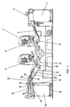
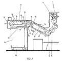
- Two-color sheetfed offset press 2 become paper sheets successively by means of an automated sheet feed 4 from one arranged in a sheet feeder 6 of the printing press 2 Paper stack 8 to a feed drum 10 of a first Transfer printing unit 12 and then through the first printing unit 12 and possibly transported a second printing unit 14 in order to or to print on both sides in one or more colors.
- a sheet delivery 22 of the printing machine 2 From an impression cylinder 16 of the second printing unit 14 take over delivery gripper systems 18 of a chain conveyor 20 a sheet delivery 22 of the printing machine 2, the printed sheets and transport them through a housing 24 of the sheet delivery 22 to a sheet stack 26 on which the sheet then are stacked on top of each other.
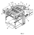
- the chain conveyor 20 is in the essentially two in opposite side Guide rails 28 (Fig. 3) guided parallel chains (not shown), which at regular intervals the gripper systems 18, also referred to as bow grippers are connected.
- the chain conveyor 20 has a lower one Bow conveyor conveyor (leading system) 30 on that of the two sprockets 31 one Delivery drum 32 moved obliquely upwards and then into the Horizontal is deflected before there are two drive sprockets 34 reached at the free end of the sheet delivery 22. His top Empty run (return system) 36 moves from the Sprockets 34 from horizontally towards the printing press 2 before it is turned diagonally down and to the delivery drum 32 is returned.
- Bow conveyor conveyor leading system
- each sheet is in Direction of movement of the conveyor run 30 through sheet baffles 38 non-contact on laterally adjustable guide arm blowers 40 over and via a sheet brake 42 arranged behind it guided and then reaches an arch exit opening 44 on the underside of the horizontal section of the housing 24 of the sheet delivery 22 to the sheet brake 42 transferred and braked sheet With the help of several arranged above the outlet opening 44 Delivery fan 46 down onto the sheet stack 26 blown. This rests on a lifting mechanism 48 that the Stack 26 in sync with the speed of the sheet feed lowers.
- a powder apparatus 50 is located horizontally above it in the space 52 between the conveyor run 30 and the empty run 36 arranged.
- the powder apparatus 52 pollinates the top of the held by the bow grippers 18 of the conveyor run 30 pressurized sheets with a fine powdered starch powder to a sticking together (putting on) of the sheets at the subsequent To prevent stacking.
- the powder apparatus 50 is made essentially from a transverse to the direction of movement of the Chain conveyor 20 through the space 52 extending tube 54, which has several powder outlet slots on its underside having.
- the starch powder is made using a pipe 54 connected blower (not shown) supplied, the Dosage of the size and color intensity of the printed Area is dependent. But not only that printed sheets, but also the chains and the sheet grabs 18 of the chain conveyor 20 dusted with the powder.
- the paper sheets carried by the chain conveyor 20 are in Direction of movement of the conveyor run 30 immediately behind the Powder apparatus 50 deflected from the inclines into the horizontal. This leads to the whip or flag effect, that is to a rocking or Flutter the back edges of the paper sheets 1. This in turn causes the powder emerging from the powder apparatus 50 is whirled up immediately after the exit. This Whirled up powder is caught by the suction of the chain conveyor 20 and by a suction-induced one in the direction of movement of the chain conveyor 20 entrained air flow.
- the Fresh air not contaminated with powder is supplied by a nozzle box 58 which over the powder suction and Air deflection trough 56 in the area of the nozzle box 58 closed upper wall of the housing 24 is inserted and the Fresh air blows down towards the Printing machine running powder-laden air flow interrupt and thus the transport of powder carried in Prevent the direction of the press.
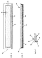
- the powder suction and air deflection tray 56 and the nozzle box 58 are arranged behind the point at which the conveyor run 30 in the horizontal is redirected, with the in the Figures 1 and 2 illustrated embodiment in Direction of movement of the conveyor run 30 before Sheet exit opening 44 and the one above it Display fans 46 are arranged while in the Fig. 3 illustrated embodiment with a shorter Sheet delivery 22 are immediately above.
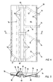
- the suction and air deflection tray 56 essentially from one thin-walled flat housing 62.
- the housing 62 extends below the side guides of the empty run 36 over the total clear width of the housing 24 of the sheet delivery 22 and forms a continuous partition between a lower, flow path running along the conveyor run 30 and a movement path of the empty run 36 arranged above it. This partition prevents the entire extent Air passes from top to bottom and vice versa.
- the housing 62 has a in the direction of movement Chain conveyor 20 upper housing wall 64 which has been bent several times, so that two shallow troughs 66 are formed by one Elevation 68 arranged between them are separated from one another.
- the upper housing wall 64 is also spaced apart arranged rows of suction slots 70 provided. While adjacent middle rows of suction slots 70 are located at the lowest points of the troughs 66 outer rows in the immediate vicinity of the opposite Arranged outer edges of the housing 62.
- Each of the rows of slots is arranged by a within the housing 62
- Suction channel 72 each connected to a suction port 74, which one of the outer edges are arranged.
- the suction nozzle 74 are each via directional and pressure control valves to control the extracted air quantities and the applied vacuum with connected to a suction fan, which a dust separator with a Centrifuge and a fine filter (not shown) is connected upstream. From the rows of suction slots 70 are the slots 70 on the outer edge on the side of the Powder apparatus 50 most heavily applied with negative pressure.
- the brush 76 is in of the trough 66 which extends from the housing 62 leaving empty strand 36 of the chain conveyor 20 first is swept over.
- the housing 62 also has a lower housing wall 80 which between the two troughs 66 and below the elevation 68 the upper housing wall 64 with a recessed upwards Bulge 82 is provided, the cross section of which is in the form of a reverse U has.
- this bulge 82 encloses the housing wall 80 between the empty strand 36 and the conveyor run 30 arranged transverse drive shaft 60, the top of which carries the housing 62.
- To reduce the Friction between the slow-running drive shaft 60 and the lower housing wall 80 is in the area of Provide bulge 82 with a Teflon coating.
- suction and air deflection tray 56 is supported the drive shaft 60 from, so that it with only a few Fastening screws on opposite side cheeks of the Chain conveyor 20 must be attached to them in place to keep.
- the Air outlet nozzles 86 are arranged in parallel rows, of which the middle one is just above the elevation 68 on the Top of the suction and air deflection tray 56 is.
- An edge 88 adjacent to the flat underside smaller lower part of the nozzle box 58 is chamfered and on its narrower faces with a series of Nozzle openings 90 provided for showering the chains of the Chain conveyor 20 serve.
- the larger top of the Nozzle box 58 is provided with a circumferential shoulder, whose narrow foreheads on the side cheeks of the Chain arm rest.
- On the bottom of the shoulder is a brush 92 is attached, the bristles 94 of which are down extend into the path of the empty run 36.
- the brush 92 also extends over the entire clear width of the Chain boom or the housing 24 and is in Direction of movement of the empty run 36 immediately behind the Brush 76 of the suction and air deflection tray 56 arranged.
- the application of compressed air to the nozzle box 58 with a Pressure between 1.5 and 3.5 bar occurs through two Air supply nozzle 96 on the top of the nozzle box 58, each communicating with a part of the nozzle rows 86.
- the amount of air supplied is such that only a part again through the suction slots 70 of the suction and Air deflector tray 56 can be sucked in while the rest Air in the top of the suction and air deflection tray 56 in Direction of the printing machine is deflected.
- the air is at a relatively low pressure of 1.5 to 2 bar supplied, while the air pressure at a downstream cleaning of the sheet delivery 22 to 3 to 3.5 bar is increased.
- Directional control valves in the to the air supply nozzle Allow 96 leading air supply lines (not shown) a clocked air supply or an optional air supply each one of the two air supply nozzles 96 or both together, i.e. to a part of each of the nozzles 86 or all nozzles 86.
- the air blown down from the nozzle box 58 flows in the sheet grippers 18 and on the chains of the chain conveyor 20 over, and shower this with clean fresh air, whereby adhering powder particles are carried down so that from the empty run 36 no further towards the printing press 2 can be transported.
- Suction slots 70 are formed as a result of the created there Vacuum also from fresh air vortex, at the Bottom of the air also in the opposite direction to Tub 56 flows back to the front and part of the whirled up powder with it, so that this through the Suction slots 70 on the adjacent outer edge of the tub 56 can be suctioned off.
- the Most of the air sucked in is from the suction of the empty run 36 carried along the same in the direction of the printing press 2, while a smaller part behind that which acts as an air switch Air suction pipe 75 down and along the press side of the powder apparatus 50 flows down.
- air can also be in front of the brushes 76, 92 be suctioned off, so that by one arising there Negative pressure a smaller part of that behind the brushes 76, 92 supplied air sucked forward through the brushes 76, 92 becomes.
- the brushes 76, 92 can also be omitted and the air flow running along the empty run 36 alone interrupted by the supply and / or extraction of air.
- the measures described above will in particular prevents powder from being whirled up by the Suction of the chain conveyor 20 entrained and over and over under the empty strand 36 generated air flow within the Housing 24 of the sheet delivery 22 in the direction of the printing press 2 is transported.
- the spread of powder is in the essentially to the area below the powder apparatus 50 and above the printed sheets below limited, which on the one hand significantly reduces powder consumption can be reduced and on the other hand both the Dust pollution in the ambient air as well as inside the Housing is significantly lower.
- both the Dust pollution in the ambient air as well as inside the Housing is significantly lower.
- the fresh air cushion accelerates between the Conveyor strand 30 and the empty strand 36 on that of the printing press 2 facing side of the powder apparatus 50 the oxidative drying of the printing inks due to the constant fresh air supply in them Area.
Description
Die Erfindung betrifft ein Verfahren und eine Vorrichtung zum Verhindern einer unkontrollierten Puderausbreitung in einer Druckmaschine. Die Erfindung betrifft insbesondere ein Verfahren, bei dem in einer Bogendruckmaschine bedruckte Bogen mittels einer Bogenfördereinrichtung durch eine Bogenauslage über einen Bogenablagestapel gefördert und dabei mit einem Puder bestäubt werden und bei dem eine unkontrollierte Ausbreitung von überschüssigem Puder verhindert wird, sowie eine Vorrichtung zum Verhindern einer unkontrollierten Ausbreitung von Puder in einem Gehäuse einer Bogenauslage einer Bogendruckmaschine, das eine Bogenfördereinrichtung zum Transport von bedruckten Bogen über einen Bogenablagestapel und eine Bestäubungseinrichtung zum Bestäuben der bedruckten Bogen mit einem Puder umgibt. Die Erfindung betrifft darüber hinaus eine Bogenauslage für eine Bogendruckmaschine und eine Bogendruckmaschine mit einer derartigen Vorrichtung.The invention relates to a method and an apparatus for Prevent an uncontrolled spread of powder in one Press. The invention relates in particular to a Process in which sheets printed in a sheet-fed printing machine by means of a sheet conveyor through a sheet delivery conveyed through a stack of sheets and with one Powder are dusted and one is uncontrolled Spread of excess powder is prevented, as well a device for preventing an uncontrolled Spreading powder in a sheet delivery case a sheet printing machine that a sheet conveyor for Transport of printed sheets via a sheet stack and a dusting device for dusting the printed Powder surrounds bow. The invention relates above also a sheet delivery for a sheet printing machine and a Sheet printing machine with such a device.
Beim Bogenoffsetdruck in größeren Bogenoffsetdruckmaschinen werden die ein- oder beidseitig bedruckten Papierbogen nach ihrem Durchlauf durch die Druckwerke der Druckmaschine gewöhnlich von einem Kettenförderer der Papier- oder Bogenauslage, d.h. einem Kettenförderer mit zwei parallelen, durch Auslagegreifersysteme oder Bogengreifer verbundenen Ketten aufgenommen und innerhalb eines die Bogenauslage und die Druckwerke der Druckmaschine umschließenden Gehäuses über einen Bogenstapel transportiert, auf dem sie anschließend übereinander abgelegt werden. Da die Druckfarbe beim Übereinanderstapeln der Bogen noch nicht vollständig getrocknet ist, wird bei den meisten auf dem Markt befindlichen Bogenoffsetdruckmaschinen mindestens eine Oberfläche jedes Bogens vor dem Ablegen auf dem Stapel mit einem Puder bestäubt, der auf den bedruckten Partien der Papierbogen haftet und ein Ablegen, d.h. ein Zusammenkleben der Papierbogen im Bogenstapel verhindert. Als Puder werden gewöhnlich feinpulverige Kartoffelstärke oder andere pulverförmige Stärkeprodukte verwendet. Zum Aufbringen des Puders dient ein sogenannter Puderapparat oder eine andere Bestäubungseinrichtung, die in der Regel in einem Zwischenraum zwischen dem die Bogen transportierenden vorlaufenden Fördertrum und dem rücklaufenden Leertrum des Kettenförderers angeordnet ist und die auf dem unten liegenden Fördertrum des Kettenförderers vorbeitransportierten Bogen von oben her mit dem Puder bestäubt.For sheetfed offset printing in larger sheetfed offset presses are the paper sheets printed on one or both sides after their passage through the printing units of the printing press usually from a paper or chain conveyor Sheet delivery, i.e. a chain conveyor with two parallel, connected by delivery gripper systems or sheet grippers Chains included and within a the sheet delivery and enclosing the printing units of the printing press housing transported a stack of sheets on which she then are stacked on top of each other. Since the printing ink at The sheets are not yet completely stacked on top of one another is dried at most on the market located sheetfed offset presses at least one Surface of each sheet before placing it on the stack with powdered on the printed areas of the Sheets of paper stick and a deposit, i.e. a sticking together the sheet of paper in the sheet stack prevents. Be as powder usually fine powdered potato starch or others powdered starch products used. To apply the Powder serves a so-called powder device or another Pollination facility, usually in a space between the leading leading the sheets Conveyor strand and the returning empty strand of the chain conveyor is arranged and the on the lower conveyor run of the Chain conveyor transported sheets from above with dusted the powder.
Schnellaufende Bogenoffsetdruckmaschinen für den Druck hoher Auflagen, wie beispielsweise die unter der Bezeichnung Heidelberg Speedmaster von der Fa. Heidelberger Druckmaschinen AG verkauften Bogenoffsetdruckmaschinen, sind gewöhnlich mit einer Hochstapelbogenauslage versehen, um mehr Bogen stapeln zu können. Bei derartigen Bogenauslagen erstreckt sich das Fördertrum des Kettenförderers zuerst schräg nach oben und wird dann in die Horizontale umgelenkt, um die bedruckten Bogen vor der Freigabe über dem Bogenablagestapel horizontal auszurichten. Die Bestäubungseinrichtung ist dort gewöhnlich kurz vor dem oberen Ende des schrägen Teilstücks des Fördertrums im Zwischenraum zwischen diesem und dem Leertrum des Kettenförderers angeordnet.High-speed sheetfed offset presses for printing high Requirements such as those under the label Heidelberg Speedmaster from Heidelberger Druckmaschinen AG sheetfed offset presses are usually sold with a high-stack sheet delivery to stack more sheets to be able to. With such sheet displays, this extends Chain conveyor conveyor run first diagonally upwards and is then redirected into the horizontal to the printed Sheets horizontally before releasing them above the sheet filing stack align. The pollination facility is common there just before the upper end of the sloping section of the Funding runs in the space between this and the empty run arranged of the chain conveyor.
Beim Betrieb derartiger Bogenoffsetdruckmaschinen hat man festgestellt, daß erheblich mehr Puder verbraucht wird, als zum Bestäuben der Papierbogen eigentlich erforderlich ist. Gleichzeitig weist die Umgebungsluft um die Bogenauslage herum einen stark erhöhten, durch Puderpartikel verursachten Staubgehalt auf, während sich im Inneren des Gehäuses der Bogenauslage auf beweglichen und unbeweglichen Teilen verstärkt Puderablagerungen bilden. Der höhere Staubgehalt in der Umgebungsluft, der teilweise fast als Pudernebel bezeichnet werden kann, wird vom Bedienungspersonal als äußerst unangenehm empfunden, während Puderablagerungen im Inneren des Gehäuses, insbesondere auf beweglichen Teilen, einen erhöhten Verschleiß und längere Stillstandszeiten der Maschine infolge häufiger Reinigungs- und Wartungsarbeiten zur Folge haben.When operating such sheetfed offset printing presses one has found that significantly more powder is consumed than is actually required for dusting the paper sheets. At the same time, the ambient air points around the sheet delivery a greatly increased, caused by powder particles Dust content while inside the case of the Sheet delivery on moving and immovable parts increasingly form powder deposits. The higher dust content in the ambient air, some of which is almost a powder mist can be referred to by the operating personnel as felt extremely uncomfortable, while powder deposits in the Interior of the housing, especially on moving parts, increased wear and longer downtimes Machine due to frequent cleaning and maintenance work Consequence.
Bei Untersuchungen des Anmelders zur Klärung der Ursachen der puderbedingten Staubbelastung in der Umgebungsluft sowie der Puderablagerungen im Gehäuse der Bogenauslage wurde festgestellt, daß in den Bogenauslagen herkömmlicher Offsetdruckmaschinen in großem Umfang Luftturbulenzen auftreten. Diese Luftturbulenzen werden unter anderem dadurch verursacht, daß jeweils unter- und oberhalb des Fördertrums und des Leertrums des Bogenauslegers durch die Sogwirkung der sich bewegenden Bogengreifer und Ketten Luft in Bewegungsrichtung des jeweiligen Trums mitgerissen wird, daß vom Fördertrum mitgeführte bedruckte Bogen flattern oder beim Umlenken aus der Schräge in die Horizontale mit ihrem hinteren Rand nach oben wippen (sogenannter Peitschen- oder Fahnen-Effekt), sowie dadurch, daß aus dem sogenannten Bogenleitblech Luft von unten her gegen den Bogen geblasen wird, um diesen berührungsfrei über das Leitblech zu führen, wobei jedoch ein Teil dieser Luft zwischen den benachbarten Bogen sowie seitlich an den Bogen vorbei nach oben strömt.In investigations by the applicant to clarify the causes of the powder-related dust pollution in the ambient air as well as the Powder deposits were in the housing of the sheet delivery found that more conventional in the sheet displays Large-scale offset printing machines air turbulence occur. This causes turbulence among other things causes that below and above the conveyor run and the empty run of the bow boom by the suction effect of the moving claws and chains air in Direction of movement of the respective run is carried away that printed sheets carried by the conveyor belt flutter or at Redirect from the slant to the horizontal with its rear Rock the edge upwards (so-called whip or flag effect), and in that from the so-called sheet guide plate Air is blown against the bow from below, around this to run without contact over the baffle, but with a Part of this air between the neighboring arches as well flows upwards past the arch.
Durch diese Luftturbulenzen wird ein großer Teil des aus der Puderbestäubungseinrichtung austretenden Puders verwirbelt und von der Luft mitgerissen, so daß er nicht wie gewünscht unmittelbar unterhalb der Puderbestäubungseinrichtung auf die Oberfläche des Bedruckstoffs gelangt. Statt dessen wird der Puder durch die Luftströmungen, insbesondere diejenigen entlang der beiden Trume des Bogenauslegers, über den gesamten Innenraum der Bogenauslage verteilt. Dies führt nicht nur zu einem erhöhten Verschleiß an beweglichen Teilen und längeren Stillstandszeiten zur Reinigung der Bogenauslage, sondern auch zu einer Belästigung des Bedienungspersonals, weil der aufgewirbelte Puder außerdem durch sämtliche Öffnungen der Bogenauslage, insbesondere durch die Bogenaustrittsöffnung und Luftaustrittsgitter auf der Oberseite des Gehäuses, in die Umgebung austritt.Due to this air turbulence, a large part of the Powder dusting device emerging and swirled carried away by the air, so that it does not work as desired immediately below the powdering device Surface of the substrate. Instead, the Powder through the air currents, especially those along the two strands of the bow boom, over the entire Distributed interior of the sheet delivery. This not only leads to increased wear on moving parts and longer ones Downtimes for cleaning the sheet delivery, but also to bother the operator because of whirled powder also through all openings of the Sheet delivery, especially through the sheet exit opening and Air outlet grille on the top of the housing, in the Environment emerges.
Um die hohe Staubbelastung der Umgebungsluft zu verringern und weitere, durch überschüssigen Puder verursachte Probleme zu beseitigen, wird in der US 5,265,563 eine oberhalb des Bogenstapels und einer Bogenaustrittsöffnung angeordnete Absaughaube vorgeschlagen, die dazu dient, puderbelastete Luft nach oben durch das Leertrum hindurch abzusaugen, um sie dann zu reinigen. Ein Teil der puderbelasteten Luft wird jedoch beim Hindurchtritt durch das Leertrum durch den Sog desselben mitgerissen und strömt entlang des Leertrums in Richtung der Druckmaschine.To reduce the high dust pollution in the ambient air and additional problems caused by excess powder eliminate, is in US 5,265,563 above the Sheet stack and a sheet exit opening arranged Extractor hood is proposed, which is used to remove air contaminated with powder aspirate upwards through the empty strand and then to clean. However, some of the air contaminated with powder becomes when passing through the empty run through the suction of the same swept along and flows along the empty strand towards the Press.
Weiter ist in der DE 42 07 118 A1 eine Bogenauslage einer Bogendruckmaschine offenbart, in deren Gehäuse in der Nähe der Puderbestäubungseinrichtung über dem Fördertrum Vorrichtungen vorgesehen sind, um überschüssigen Puder abzusaugen und damit dessen unkontrollierte Ausbreitung zu verhindern. Derartige Vorrichtungen saugen einen Großteil des ausgebrachten Puders sofort wieder ab, was jedoch häufig zur Folge hat, daß das Bedienungspersonal die Puderzufuhr steigert und so noch mehr Puder verbraucht wird. Das Problem einer Puderverbreitung durch einen Luftsog im Inneren des Gehäuses wird hingegen nicht gelöst.In DE 42 07 118 A1, a sheet delivery is a Sheet printing machine disclosed in the housing near the Powder dusting device above the conveyor belt devices are provided to suck off excess powder and thus to prevent its uncontrolled spread. such Devices suck a large part of the powder applied immediately, which often has the consequence that the Operating personnel increases the powder supply and so much more Powder is consumed. The problem of powder spread an air suction inside the housing, however unsolved.
Außerdem ist in der DE AS 2 148 757 eine Bogenauslage einer Druckmaschine offenbart, bei der entlang eines oberen horizontalen Teilstücks des Leertrums eines Bogenförderers eine Reinigungsvorrichtung vorgesehen ist, die ein Gehäuse, mehrere im Gehäuse angeordnete Bürsten und eine Absaugvorrichtung umfaßt, um den durch die Bürsten von den Ketten und Greifersystemen abgereinigten Puder abzusaugen. Jedoch wurde dort weder das Problem einer Puderausbreitung durch die vom Sog des Leertrums mitgerissene puderbelastete Luft erkannt, noch ist die beschriebene Reinigungsvorrichtung geeignet, einen Transport von puderbelasteter Luft in Richtung der Druckmaschine zu verhindern, da sowohl zwischen dem Gehäuse der Reinigungsvorrichtung und den benachbarten Wänden der Bogenauslage als auch innerhalb des Gehäuses auf beiden Seiten der Bürsten breite offene Strömungsquerschnitte vorhanden sind, die einen Hindurchtritt von puderbelasteter Luft entlang des Bewegungspfades des Leertrums ermöglichen.In addition, in DE AS 2 148 757 a sheet delivery is a Printing machine disclosed in the along an upper horizontal section of the empty run of a sheet conveyor a cleaning device is provided which has a housing, several brushes arranged in the housing and one Suction device includes the brushes from the Vacuum chains and gripper systems of cleaned powder. However, there was no problem of powder spreading there due to the powder load entrained by the suction of the empty run Air detected, the cleaning device described is still suitable to transport powder-laden air in the direction to prevent the printing press, since both between the Housing of the cleaning device and the adjacent walls the sheet delivery as well as inside the case on both Wide open flow cross-sections on the sides of the brushes are present that have a passage of powdered Allow air along the movement path of the empty run.
Ausgehend hiervon liegt der Erfindung die Aufgabe zugrunde, ein Verfahren und eine nachträglich montierbare und/oder fabrikmäßig montierte Vorrichtung der eingangs genannten Art bereitzustellen, die während des Druckbetriebs eine Verringerung der Staubbelastung in der Umgebung der Druckmaschine ermöglicht und die Bildung von Puderablagerungen innerhalb des Gehäuses weitgehend verhindert.Proceeding from this, the invention is based on the object a method and a retrofittable and / or Factory assembled device of the type mentioned To provide a during printing Reduction of dust pollution in the vicinity of the Printing machine enables and the formation of powder deposits largely prevented within the housing.
Diese Aufgabe wird erfindungsgemäß durch die in den beiliegenden Patentansprüchen 1 für das Verfahren, 14 für die Vorrichtung, sowie 32 für eine mit der Vorrichtung ausgestaltete Bogendruckmaschine angegebenen Merkmalskombinationen gelöst. Danach wird eine im Gehäuse der Bogenauslage entlang eines Leertrums der Bogenfördereinrichtung in Richtung der Druckmaschine verlaufende, durch den vorangehenden Vorbeitritt an der Bestäubungseinrichtung mit überschüssigem Puder belastete Luftströmung an mindestens einer Unterbrechungsstelle zwischen dem freien Ende der Bogenauslage und der Druckmaschine unterbrochen, um einen Transport von mitgeführtem Puder in Richtung der Druckmaschine zu verhindern.This object is achieved by the in the enclosed patent claims 1 for the method, 14 for the Device, and 32 for one designed with the device Sheet combinations specified feature combinations solved. Then one is in the housing along the sheet delivery an empty run of the sheet conveyor in the direction of Printing machine running through the previous pass at the pollinator with excess powder polluted air flow on at least one Interruption point between the free end of the sheet delivery and the printing machine is interrupted to carry out a transport of carried powder in the direction of the printing press prevent.
Die Erfindung sieht vor, daß jeglicher entlang des Bewegungspfades des Leertrums vorhandene strömungspfad, durch den puderbelastete Luft vom freien Ende der Bogenauslage zur Druckmaschine strömen kann, an mindestens einer Stelle zwischen dem freien Ende der Auslage und der Druckmaschine versperrt wird, um damit die Ausbildung einer in Richtung der Druckmaschine verlaufenden Luftströmung und damit einen Transport von Puder in dieser Luftströmung zur Druckmaschine zu verhindern. Dazu ist es erforderlich, an der Unterbrechungsstelle den gesamten freien Strömungsquerschnitt zwischen einer oberen Wand des Gehäuses, den beiden Seitenwänden des Gehäuses und einer im Zwischenraum zwischen dem Leertrum und dem Fördertrum angeordneten Trennwand oder dergleichen im wesentlichen vollständig zu versperren, so daß ein Hindurchtritt von puderbelasteter Luft durch diesen Abschnitt des Strömungspfades nahezu vollständig unterbunden wird.The invention provides that everyone along the movement path of the empty strand Existing flow path through which powder-contaminated air from the free end of the sheet delivery can flow to the printing press, at least one place between the free end of the Delivery and the printing press is blocked to allow the Formation of a running in the direction of the printing press Air flow and thus a transport of powder in it To prevent air flow to the press. It is for that required the entire free at the point of interruption Flow cross-section between an upper wall of the housing, the two side walls of the housing and one in the space arranged between the empty strand and the conveyor strand Partition or the like essentially completely block so that a passage of powdered air through this section of the flow path almost completely is prevented.
Gemäß einer weiteren bevorzugten Ausgestaltung der Erfindung wird die Luftströmung möglichst nahe am freien Ende der Bogenauslage unterbrochen, d.h. zweckmäßig in einem oberen horizontalen Teilstück der Bogenauslage und bevorzugt oberhalb von einer Antriebswelle eines Hubmechanismus für den Bogenablagestapel, wo ausreichend Platz für die benötigten Einrichtungen vorhanden ist. Da sich die Antriebswelle sehr langsam dreht, kann sie zudem gut als Auflager oder Träger für einen Teil der Einrichtungen dienen.According to a further preferred embodiment of the invention the air flow is as close as possible to the free end of the Sheet delivery interrupted, i.e. expedient in an upper horizontal section of the sheet delivery and preferably above from a drive shaft of a lifting mechanism for the Sheet storage stack, where there is enough space for the required Facilities is available. Because the drive shaft is very turns slowly, it can also serve as a support or carrier for serve part of the facilities.
Die Unterbrechung der Luftströmung kann mit pneumatischen und/oder mit mechanischen Mitteln erfolgen, wobei eine Kombination bevorzugt wird. Bei einer Unterbrechung mit pneumatischen Mitteln wird bevorzugt Luft an der Unterbrechungsstelle so aus dem Gehäuse abgesaugt und/oder ein Strom sauberer, d.h. nicht mit Puder belasteter Luft so in das Gehäuse der Bogenauslage zugeführt, daß der Strömungspfad durch einen Luftvorhang oder Luftstrom versperrt wird, der das Leertrum durchsetzt und ausreichend breit und tief ist, um einen Hindurchtritt von puderbelasteter Luft zwischen der oberen Wand des Gehäuses, den beiden Seitenwänden des Gehäuses und der zwischen Leertrum und Fördertrum angeordneten Trennwand oder dergleichen zu verhindern.The air flow can be interrupted with pneumatic and / or by mechanical means, one Combination is preferred. With an interruption with pneumatic means is preferred air at the Interruption point sucked out of the housing and / or a Electricity cleaner, i.e. air not contaminated with powder so in that Housing of the sheet delivery fed that the flow path is blocked by an air curtain or airflow that the Empty strand is interspersed and is sufficiently wide and deep to a passage of powdered air between the top wall of the housing, the two side walls of the housing and that arranged between the empty run and the conveyor run Prevent partition or the like.
Dazu umfassen die zur Unterbrechung der Luftströmung dienenden Einrichtungen vorzugsweise eine Luftzufuhreinrichtung, welche aus der Umgebung angesaugte und nicht mit Puder belastete Luft so in das Gehäuse leitet, daß sie das Leertrum quer zu dessen Bewegungsrichtung vertikal durchströmt, und/oder eine Luftabsaugeinrichtung, die quer zur Bewegungsrichtung des Leertrums Luft aus dem Strömungspfad saugt, vorzugsweise gegenüber von der Luftzufuhreinrichtung, um mindestens einen Teil der eingeleiteten Luft zusammen mit dem von den Ketten und Bogengreifern der Fördereinrichtung abgeduschten Puder nach dem Hindurchtritt durch den Strömungspfad abzusaugen und zweckmäßig in einem nachgeschalteten Abscheider von mitgeführtem Puder zu reinigen.For this purpose include those used to interrupt the air flow Devices preferably an air supply device, which Air sucked in from the environment and not contaminated with powder conducts into the housing so that it crosses the empty strand to it Flow direction vertical, and / or one Air extraction device, which is transverse to the direction of movement of the Empty strand sucks air from the flow path, preferably opposite the air supply device by at least one Part of the air introduced together with that from the chains and sheet grippers of the conveyor showered powder aspirate after passing through the flow path and expedient in a downstream separator from to clean carried powder.
Die zugeführte Luft wird bevorzugt von oben her in das Gehäuse geleitet und unterhalb des Leertrums abgesaugt, um abgeduschten Puder in Richtung der Schwerkraft abzuführen. Eine umgekehrte Anordnung ist jedoch ebenfalls denkbar.The air supplied is preferably from above into the housing passed and vacuumed below the empty strand to to discharge showered powder in the direction of gravity. A reverse arrangement is also conceivable.
Um eine möglichst ungestörte Ausbildung des Luftvorhangs sicherzustellen, sind vorzugsweise in Bewegungsrichtung des Leertrums vor der Luftzufuhreinrichtung mehrere Bürsten vorgesehen, die sich über die gesamte Breite des vorhandenen Strömungspfades erstrecken und deren Borsten von oben und unten in den Bewegungspfad des Leertrums ragen und sich dort berühren oder überlappen, um so den Strömungspfad auch über seine gesamte Höhe und zwischen den einzelnen Bogengreifern zu versperren und gleichzeitig die Bogengreifer und Ketten von anhaftendem Puder zu reinigen.To make the air curtain as undisturbed as possible ensure are preferably in the direction of movement Empty strand in front of the air supply device, several brushes provided that spanned the full width of the existing Extend flow paths and their bristles from above and protrude below in the path of movement of the empty run and there touch or overlap so the flow path also over its entire height and between the individual bow grabs too block and at the same time the bow grabs and chains from to clean adhering powder.
Die Reinigung der Ketten und Bogengreifer ist für eine Verhinderung der Puderausbreitung ebenfalls von Bedeutung, da sich auch vom Kettenförderer mitgeführter und später durch Vibrationen oder dergleichen freigesetzter Puder im Gehäuse der Bogenauslage ablagert und besonders in der Nähe einer letzten Druckstation der Druckmaschine zu einem erhöhten Verschleiß an empfindlichen Bauteilen sowie zu einer schlechteren Druckqualität führen kann. Cleaning the chains and bow grab is for one Prevention of powder spread also important because also carried by the chain conveyor and later on Vibrations or the like released powder in the housing of the sheet delivery and especially near one last printing station of the printing press to an elevated Wear on sensitive components as well as on one poor print quality.
Gemäß einer besonders bevorzugten Ausgestaltung der Erfindung wird hinter einem Bürstenpaar Luft aus der Umgebung oder Atmosphäre von oben her durch das Leertrum hindurch in das Gehäuse der Bogenauslage eingeblasen und mindestens ein Teil der eingeblasenen Luft unterhalb des Leertrums wieder abgesaugt, so daß durch die Bürsten hindurchgetretene puderbelastete Luft durch die von oben zugeführte Luft nach unten mitgerissen und unterhalb des Leertrums zusammen mit dem durch die Bürsten vom Kettenförderer gelösten und/oder durch die Lufteinblasung abgeduschtem Puder abgesaugt wird.According to a particularly preferred embodiment of the invention is air from the environment behind a pair of brushes or Atmosphere from above through the empty strand into the Blown in housing of the sheet delivery and at least a part the blown air below the empty strand again aspirated, so that passed through the brushes air contaminated with powder by the air supplied from above carried along below and below the empty strand together with the detached from the chain conveyor by the brushes and / or by the air blowing in the showered powder is sucked off.
Eine weitere bevorzugte Ausgestaltung der Erfindung sieht vor, daß im Bereich der Unterbrechungsstelle oder in Bewegungsrichtung des Leertrums dahinter nicht mit Puder belastete Luft von außen in das Gehäuse zugeführt wird. Dadurch wird verhindert, daß sich in Bewegungsrichtung des Leertrums hinter der Unterbrechungsstelle ein Unterdruck ausbildet, der wiederum zu einer Ansaugung von puderbelasteter Luft in diesen Bereich führen könnte. Alternativ oder zusätzlich können die Luftzufuhr und ggf. die Luftabsaugung im Bereich der Unterbrechungsstelle auch so eingestellt werden, daß die zugeführte Luftmenge größer als die abgesaugte Luftmenge ist, um dadurch die Entstehung eines Unterdrucks zu vermeiden.Another preferred embodiment of the invention provides that in the area of the interruption point or in Direction of movement of the empty strand behind, not with powder contaminated air is fed into the housing from the outside. This prevents that in the direction of movement Vacuum runs behind the point of interruption a negative pressure trains, which in turn leads to a suction of powdered Air could lead to this area. Alternatively or in addition, the air supply and possibly the air extraction in the Range of the interruption point can also be set that the amount of air supplied is greater than that extracted Amount of air is, thereby creating a negative pressure avoid.
Außerdem kann durch die Zufuhr der nicht mit Puder belasteten Luft der vom Leertrum erzeugte Luftsog genutzt werden, um diese Luft ggf. zusammen mit der an der Oberseite einer auch als Trennwand wirkenden Absaug- und Luftablenkeinrichtung umgelenkten eingeblasenen Luft oberhalb der Bestäubungseinrichtung vorbei in Richtung der Druckmaschine zu leiten. Diese nicht mit Puder belastete Luft bildet dann zwischen der Bestäubungseinrichtung und dem Leertrum sowie zwischen der Bestäubungseinrichtung und der Druckmaschine ein Luftpolster, das ebenfalls mit dazu beiträgt, eine Ausbreitung des Puders bis in die Nähe der Druckmaschine zu verhindern. In addition, the powder can not be loaded with the supply Air the air suction generated by the empty run can be used to this air if necessary together with that at the top of one too suction and air deflection device acting as a partition redirected blown air above the Pollination device past in the direction of the printing press conduct. This air, which is not contaminated with powder, then forms between the pollination facility and the empty strand as well between the pollinator and the press Air cushion, which also helps spread to prevent the powder from getting close to the press.
Darüber hinaus kommt es an der Unterseite des Luftpolsters zur Ausbildung von Luftwirbeln, an deren Unterseite Frischluft zurück in Richtung des freien Endes der Auslage strömt. Dies wiederum bewirkt, daß zwischen der Bestäubungseinrichtung und der Absaugeinrichtung ein Teil des aufgewirbelten Puders zu einer oder mehreren Ansaugöffnungen am hinteren Rand der Absaugeinrichtung gelenkt wird, wo er abgesaugt werden kann. Zwischen der Bestäubungseinrichtung und der Druckmaschine strömt hingegen Frischluft an der Unterseite der Wirbel zurück in Richtung der Bestäubungseinrichtung, wodurch der aufgewirbelte Puder unmittelbar oberhalb der bedruckten Bogen in Richtung des freien Endes der Auslage gedrückt wird. Überraschenderweise konnte dadurch eine gleichmäßigere beidseitige Bestäubung der Bogen erreicht werden.In addition, it occurs on the underside of the air cushion Formation of air vortices with fresh air on the underside flows back towards the free end of the delivery. This in turn causes between the pollinator and part of the whirled powder to the suction device one or more intake openings at the rear edge of the Suction device is steered where it can be suctioned off. Between the pollinator and the press fresh air, however, flows back at the bottom of the vortex towards the pollinator, causing the whirled up powder immediately above the printed sheets is pressed towards the free end of the delivery. Surprisingly, this allowed a more even one pollination of the sheets on both sides can be achieved.
Im folgenden wird die Erfindung anhand von in der Zeichnung
dargestellten Ausführungsbeispielen näher erläutert. Es
zeigen:
In der in Fig. 1 der Zeichnung schematisch dargestellten
Zweifarben-Bogenoffsetdruckmaschine 2 werden Papierbogen
nacheinander mittels einer automatisierten Bogenzufuhr 4 von
einem in einer Bogenanlage 6 der Druckmaschine 2 angeordneten
Papierstapel 8 an eine Anlegetrommel 10 eines ersten
Druckwerks 12 übergeben und dann durch das erste Druckwerk 12
und ggf. ein zweites Druckwerk 14 transportiert, um sie ein-
oder beidseitig ein- oder mehrfarbig zu bedrucken.Shown schematically in Fig. 1 of the drawing
Two-color sheetfed offset
Von einem Gegendruckzylinder 16 des zweiten Druckwerks 14
übernehmen Auslagegreifersysteme 18 eines Kettenförderers 20
einer Bogenauslage 22 der Druckmaschine 2 die bedruckten Bogen
und transportieren sie durch ein Gehäuse 24 der Bogenauslage
22 bis über einen Bogenablagestapel 26, auf dem die Bogen dann
übereinander abgelegt werden. Der Kettenförderer 20 besteht im
wesentlichen aus zwei in gegenüberliegenden seitlichen
Führungsschienen 28 (Fig. 3) geführten parallelen Ketten
(nicht dargestellt), welche in regelmäßigen Abständen durch
die auch als Bogengreifer bezeichneten Greifersysteme 18
verbunden sind. Der Kettenförderer 20 weist ein unteres, die
Bogen transportierendes Fördertrum (vorlaufendes System) 30
auf, das sich von den beiden Kettenrädern 31 einer
Auslagetrommel 32 aus schräg nach oben bewegt und dann in die
Horizontale umgelenkt wird, bevor es zwei Antriebskettenräder
34 am freien Ende der Bogenauslage 22 erreicht. Sein oberes
Leertrum (rücklaufendes System) 36 bewegt sich von den
Kettenrädern 34 aus horizontal in Richtung der Druckmaschine
2, bevor es schräg nach unten umgelenkt und zur Auslagetrommel
32 zurückgeführt wird.From an
Nach der Übergabe an die Bogengreifer 18 wird jeder Bogen in
Bewegungsrichtung des Fördertrums 30 durch Bogenleitbleche 38
berührungslos an seitlich verstellbaren Leitbügelbläsern 40
vorbei und über eine dahinter angeordnete Bogenbremse 42
geführt und erreicht anschließend eine Bogenaustrittsöffnung
44 auf der Unterseite des horizontalen Teilstücks des Gehäuses
24 der Bogenauslage 22. Dort werden die seitens der Greifer 18
an die Bogenbremse 42 übergebenen und abgebremsten Bogen mit
Hilfe mehrerer, über der Austrittsöffnung 44 angeordneter
Auslagelüfter 46 nach unten auf den Bogenablagestapel 26
geblasen. Dieser ruht auf einem Hubmechanismus 48, der den
Stapel 26 synchron zur Geschwindigkeit der Bogenzufuhr
absenkt.After delivery to the
In der Nähe des oberen Endes des schrägen Teilstücks des
Kettenförderers 20 kurz vor der Umlenkung des Fördertrums 30
in die Horizontale ist oberhalb desselben ein Puderapparat 50
im Zwischenraum 52 zwischen dem Fördertrum 30 und dem Leertrum
36 angeordnet. Der Puderapparat 52 bestäubt die Oberseite der
von den Bogengreifern 18 des Fördertrums 30 gehaltenen
druckfeuchten Bogen mit einem feinpulverigen Stärkepuder, um
ein Zusammenkleben (Anlegen) der Bogen beim anschließenden
Übereinanderstapeln zu verhindern. Der Puderapparat 50 besteht
im wesentlichen aus einem quer zur Bewegungsrichtung des
Kettenförderers 20 durch den Zwischenraum 52 verlaufenden Rohr
54, das auf seiner Unterseite mehrere Puderaustrittsschlitze
aufweist. Der Stärkepuder wird mit Hilfe eines mit dem Rohr 54
verbundenen Gebläses (nicht dargestellt) zugeführt, wobei die
Dosierung von der Größe und Farbintensität der bedruckten
Flächen abhängig ist. Dabei werden allerdings nicht nur die
bedruckten Bogen, sondern auch die Ketten und die Bogengreifer
18 des Kettenförderers 20 mit dem Puder bestäubt.Near the top of the sloping section of the
Die vom Kettenförderer 20 mitgeführten Papierbogen werden in
Bewegungsrichtung des Fördertrums 30 unmittelbar hinter dem
Puderapparat 50 aus der Schrägen in die Horizontale umgelenkt.
Dabei kommt es zu dem eingangs bereits erwähnten Peitschen-
oder Fahnen-Effekt, das heißt zu einem Hochwippen oder
Flattern der hinteren Ränder der Papierbogen 1. Dies wiederum
bewirkt, daß der aus dem Puderapparat 50 austretende Puder
unmittelbar nach dem Austritt stark verwirbelt wird. Dieser
aufgewirbelte Puder wird vom Sog des Kettenförderers 20 erfaßt
und durch eine vom Sog hervorgerufene, in Bewegungsrichtung
des Kettenförderers 20 verlaufende Luftströmung mitgeführt.The paper sheets carried by the
Um eine Verbreitung des aufgewirbelten Puders innerhalb des
Gehäuses 24 der Bogenauslage 22 und insbesondere entlang des
Bewegungspfades des Leertrums 36 in Richtung der Druckmaschine
2 zu verhindern, die durch Öffnungen des Gehäuses 24
austretenden Pudermengen zu reduzieren und die mit Puder
bestäubten Ketten und Bogengreifer 18 des Kettenförderers 20
zu reinigen, ist in Bewegungsrichtung des Fördertrums 30
hinter dem Puderapparat 50 eine von oben her durch das
Leertrum 36 hindurch mit Frischluft beaufschlagbare
kombinierte Absaug- und Luftablenkwanne 56 im Zwischenraum 52
zwischen dem Fördertrum 30 und dem Leertrum 36 angeordnet. Die
Zufuhr der nicht mit Puder belasteten Frischluft erfolgt durch
einen Düsenkasten 58, der über der Puderabsaug- und
Luftablenkwanne 56 in die im Bereich des Düsenkastens 58
geschlossene obere Wand des Gehäuses 24 eingesetzt ist und die
Frischluft nach unten bläst, um die in Richtung der
Druckmaschine verlaufende puderbelastete Luftströmung zu
unterbrechen und so den Transport von mitgeführtem Puder in
Richtung der Druckmaschine zu verhindern.In order to spread the whirled powder within the
Die Puderabsaug- und Luftablenkwanne 56 und der Düsenkasten 58
sind hinter der Stelle angeordnet, an der das Fördertrum 30 in
die Horizontale umgelenkt wird, wobei sie bei dem in den
Figuren 1 und 2 dargestellten Ausführungsbeispiel in
Bewegungsrichtung des Fördertrums 30 vor der
Bogenaustrittsöffnung 44 und den darüber angebrachten
Auslagelüftern 46 angeordnet sind, während sie sich bei dem in
Fig. 3 dargestellten Ausführungsbeispiel mit kürzerer
Bogenauslage 22 unmittelbar darüber befinden. The powder suction and
In beiden Fällen wird die Absaug- und Luftablenkwanne 56 von
einer im Zwischenraum 52 zwischen dem Leertrum 36 und dem
Fördertrum 36 angeordneten quer verlaufenden Antriebswelle 60
des Hubmechanismus 48 getragen.In both cases, the suction and
Wie am besten in den Figuren 3, 4 und 5 dargestellt, besteht
die Absaug- und Luftablenkwanne 56 im wesentlichen aus einem
dünnwandigen flachen Gehäuse 62. Das Gehäuse 62 erstreckt sich
unterhalb der seitlichen Führungen des Leertrums 36 über die
gesamte lichte Weite des Gehäuses 24 der Bogenauslage 22 und
bildet eine durchgehende Trennwand zwischen einem unteren,
entlang des Fördertrums 30 verlaufenden Strömungspfad und
einem darüber angeordneten Bewegungspfad des Leertrums 36.
Diese Trennwand verhindert über gesamte Erstreckung den
Hindurchtritt von Luft von oben nach unten und umgekehrt.As best shown in Figures 3, 4 and 5
the suction and
Das Gehäuse 62 besitzt eine in Bewegungsrichtung des
Kettenförderers 20 mehrfach abgeknickte obere Gehäusewand 64,
so daß zwei flache Mulden 66 gebildet werden, die durch eine
dazwischen angeordnete Erhebung 68 voneinander getrennt sind.
Die obere Gehäusewand 64 ist weiter mit im Abstand voneinander
angeordneten Reihen von Ansaugschlitzen 70 versehen. Während
sich benachbarte mittlere Reihen von Ansaugschlitzen 70
jeweils an den tiefsten Stellen der Mulden 66 befinden, sind
äußere Reihen in unmittelbarer Nähe der entgegengesetzten
Außenränder des Gehäuses 62 angeordnet. Jede der Schlitzreihen
ist durch einen innerhalb des Gehäuses 62 angeordneten
Saugkanal 72 mit je einem Saugstutzen 74 verbunden, die an
einem der Außenränder angeordnet sind. Die Saugstutzen 74 sind
jeweils über Wege- und Druckregelventile zur Steuerung der
abgesaugten Luftmengen und des angelegten Unterdrucks mit
einem Sauggebläse verbunden, dem ein Staubabscheider mit einer
Zentrifuge und einem Feinfilter (nicht dargestellt)
vorgeschaltet ist. Von den Reihen von Ansaugschlitzen 70
werden die Schlitze 70 an dem Außenrand auf der Seite des
Puderapparats 50 am stärksten mit Unterdruck beaufschlagt. The
Auf der Oberseite der oberen Gehäusewand 64 ist weiter eine
Reinigungsbürste 76 angebracht, die sich über die gesamte
lichte Weite des Gehäuses 62 erstreckt, wobei sich ihre nach
oben weisenden und in Bewegungsrichtung des Leertrums 36 etwas
angewinkelten Borsten 78 bis in den Bewegungspfad des
Leertrums 36 erstrecken. Die Bürste 76 befindet sich in
derjenigen Mulde 66, die von dem über das Gehäuse 62
hinwegtretenden Leertrum 36 des Kettenförderers 20 zuerst
überstrichen wird.On the top of the
Das Gehäuse 62 besitzt weiter eine untere Gehäusewand 80, die
zwischen den beiden Mulden 66 und unterhalb der Erhebung 68
der oberen Gehäusewand 64 mit einer nach oben eingetieften
Ausbuchtung 82 versehen ist, deren Querschnitt die Form eines
umgekehrten U besitzt. Im Bereich dieser Ausbuchtung 82
umschließt die Gehäusewand 80 die zwischen dem Leertrum 36 und
dem Fördertrum 30 angeordnete quer verlaufende Antriebswelle
60, deren Oberseite das Gehäuse 62 trägt. Zur Minderung der
Reibung zwischen der langsam laufenden Antriebswelle 60 und
der unteren Gehäusewand 80 ist diese im Bereich der
Ausbuchtung 82 mit einem Teflonüberzug versehen.The
Das heißt, die Absaug- und Luftablenkwanne 56 stützt sich auf
der Antriebswelle 60 ab, so daß sie nur mit wenigen
Befestigungsschrauben an gegenüberliegenden Seitenwangen des
Kettenförderers 20 befestigt werden muß, um sie in ihrer Lage
zu halten.That is, the suction and
Wie am besten in den Figuren 5 bis 7 dargestellt, besteht der
als Luftzufuhreinrichtung dienende Düsenkasten 58 aus einem
flachen Metallgehäuse, das auf seiner dem Leertrum 36
zugewandten ebenen Unterseite mit einer Vielzahl von
Luftaustrittsdüsen 86 versehen ist, durch welche die unter dem
Düsenkasten 58 hindurchtretenden Bogengreifer 18 des
Kettenförderers 20 mit Luft beduscht werden können. Die
Luftaustrittsdüsen 86 sind in parallelen Reihen angeordnet,
von denen die mittlere genau über der Erhebung 68 auf der
Oberseite der Absaug- und Luftablenkwanne 56 liegt.As best shown in Figures 5 through 7, the
serving as air supply
Ein an die ebene Unterseite angrenzender Rand 88 eines
kleineren Unterteils des Düsenkastens 58 ist abgeschrägt und
an seinen schmaleren Stirnseiten jeweils mit einer Reihe von
Düsenöffnungen 90 versehen, die zum Beduschen der Ketten des
Kettenförderers 20 dienen. Der größere Oberteil des
Düsenkastens 58 ist mit einer umlaufenden Schulter versehen,
deren schmale Stirnenden auf den Seitenwangen des
Kettenauslegers aufliegen. Auf der Unterseite der Schulter ist
eine Bürste 92 angebracht, deren Borsten 94 sich nach unten
bis in den Pfad des Leertrums 36 erstrecken. Die Bürste 92
erstreckt sich ebenfalls über die gesamte lichte Weite des
Kettenauslegers bzw. des Gehäuses 24 und ist in
Bewegungsrichtung des Leertrums 36 unmittelbar hinter der
Bürste 76 der Absaug- und Luftablenkwanne 56 angeordnet.An
Von dem Düsenkasten 58 bzw. einer um diesen herum angeordneten
geschlossenen oberen Gehäusewand oder Abdeckung, der Absaugund
Luftablenkwanne 56 im Zwischenraum zwischen dem Leertrum
36 und dem Fördertrum 30 und den beiden, die Führungen 28
tragenden Seitenwänden der Bogenauslage 22 wird unterhalb des
Düsenkastens 58 ein Strömungspfad begrenzt, der quer zur
Bewegungsrichtung des Leertrums 36 durch die Bürsten 76, 92
und einen vom Düsenkasten 58 zur Absaug- und Luftablenkwanne
56 strömenden Luftvorhang vollständig versperrt wird, wobei
die Begrenzungen des Strömungspfades ein seitliches Ausweichen
der puderbelasteten Luftströmung verhindern.From the
Die Beaufschlagung des Düsenkastens 58 mit Druckluft mit einem
Druck zwischen 1,5 und 3,5 bar erfolgt durch zwei
Luftzufuhrstutzen 96 auf der Oberseite des Düsenkastens 58,
die jeweils mit einem Teil der Düsenreihen 86 kommunizieren.
Die zugeführte Luftmenge ist so bemessen, daß nur ein Teil
wieder durch die Ansaugschlitze 70 der Absaug- und
Luftablenkwanne 56 angesaugt werden kann, während die übrige
Luft an der Oberseite der Absaug- und Luftablenkwanne 56 in
Richtung der Druckmaschine abgelenkt wird.The application of compressed air to the
Während des Betriebs der Druckmaschine 2 und der Bogenauslage
22 wird die Luft mit einem verhältnismäßig geringen Druck von
1,5 bis 2 bar zugeführt, während der Luftdruck bei einer
nachgeschalteten Reinigung der Bogenauslage 22 auf 3 bis 3,5
bar erhöht wird. Wegeventile in den zu den Luftzufuhrstutzen
96 führenden Luftzufuhrleitungen (nicht dargestellt) gestatten
eine getaktete Luftzufuhr bzw. eine wahlweise Luftzufuhr zu
jedem einzelnen der beiden Luftzufuhrstutzen 96 oder zu beiden
gemeinsam, d.h. zu jeweils einem Teil der Düsen 86 oder zu
sämtlichen Düsen 86.During the operation of the
Die aus dem Düsenkasten 58 nach unten geblasene Luft strömt an
den Bogengreifern 18 und an den Ketten des Kettenförderers 20
vorbei, und beduscht diese mit sauberer Frischluft, wobei
anhaftende Puderpartikel nach unten mitgeführt werden, so daß
sie vom Leertrum 36 nicht weiter in Richtung der Druckmaschine
2 transportiert werden können. Gleichzeitig bildet der nach
unten geführte Luftstrom in diesem Bereich der Bogenauslage 22
zwischen der geschlossenen Gehäuseoberseite, den Seitenwänden
der Bogenauslage 22 und der Absaug- und Luftablenkwanne 56 auf
der Unterseite eine Sperre, die verhindert, daß durch die
Bürsten 76, 92 hindurchgetretene puderbelastete Luft entlang
des Leertrums 36 in Richtung der Druckmaschine 2 strömt.The air blown down from the
Während ein Teil der zugeführten Luft mit den abgereinigten
Puderpartikeln durch die Ansaugschlitze 70 der beiden
mittleren Schlitzreihen auf der Oberseite der Absaug- und
Umlenkwanne 56 und die zugehörigen Saugkanäle 72 abgesaugt und
im nachgeschalteten Staubabscheider gereinigt wird, wird bei
der Bogenauslage 22 in Fig. 1 die restliche Luft an der
Oberseite der Wanne 56 in Bewegungsrichtung des Leertrums 36
umgelenkt, wobei sie oberhalb des Puderapparats 50 vorbei in
Richtung der Druckmaschine strömt. Dadurch wird zwischen dem
zum Puderapparat 50 benachbarten Außenrand der Absaug- und
Luftablenkwanne 56 und der Oberseite des Puderapparats 50
unterhalb des Leertrums 36 ein Frischluftpolster gebildet (in
Figuren 1 durch Pfeile dargestellt), das sich über den
Puderapparat 50 hinaus bis weit in das schräge Teilstück des
Kettenauslegers hinein erstreckt und die Ausbreitung von
aufgewirbeltem Puder in dieser Richtung verhindert.While part of the air supplied with the cleaned
Powder particles through the
Zwischen dem Puderapparat 50 und der Druckmaschine 2 bilden
sich an der dem Fördertrum 30 zugewandten Unterseite des
Luftpolsters Luftwirbel aus, vermutlich infolge des Luftsogs
des Fördertrums 30, die unmittelbar über den bedruckten Bogen
eine Umkehr der Frischluftströmung in Richtung des freien
Endes der Auslage 22 zur Folge haben und den aus dem
Puderapparat 50 austretenden Puder in der Nähe des Fördertrums
30 von der Druckmaschine 2 weg in Richtung der Umlenkung des
Fördertrums 30 drücken. Dadurch wird auch dort eine
Ausbreitung von aufgewirbeltem Puder sicher verhindert und der
Puder in der Nähe des Puderapparats gehalten.Form between the
Zwischen dem Puderapparat 50 und den auf dem benachbarten
Außenrand der Absaug- und Luftablenkwanne 56 angeordneten
Ansaugschlitzen 70 bilden sich infolge des dort angelegten
Unterdrucks ebenfalls Frischluftwirbel aus, an deren
Unterseite die Luft ebenfalls in umgekehrter Richtung zur
Wanne 56 zurück nach vorne strömt und einen Teil des
aufgewirbelten Puders mit sich führt, so daß dieser durch die
Ansaugschlitze 70 am benachbarten Außenrand der Wanne 56
abgesaugt werden kann.Between the
Durch die Unterbrechung der Luftströmung entlang des Leertrums
36 kann es druckmaschinenseitig von den Bürsten 76, 92 zur
Entstehung eines Unterdrucks Kommen, dessen Stärke von der
durch den Düsenkasten 58 zugeführten Luftmenge abhängt. Um zu
verhindern, daß durch diesen Unterdruck puderbelastete Luft
von der Puderbestäubungseinrichtung her angesaugt wird, ist
bei der in Fig. 2 dargestellten Bogenauslage 22 am oberen Ende
des schrägen Teilstücks des Gehäuses 24 in der oberen Wand des
Gehäuses 24 ein Lüftungsgitter 95 angeordnet, durch das aus
der Umgebung der Bogenauslage 22 nicht mit Puder belastete
Luft ins Innere des Gehäuses 24 gesaugt werden kann. Der
größte Teil der angesaugten Luft wird vom Sog des Leertrums 36
entlang desselben in Richtung der Druckmaschine 2 mitgeführt,
während ein kleinerer Teil hinter dem als Luftweiche wirkenden
Luftabsaugrohr 75 nach unten und druckmaschinenseitig entlang
des Puderapparats 50 nach unten strömt. Der an der Oberseite
der Absaug- und Luftablenkwanne 56 umgelenkte Teil der durch
den Düsenkasten 58 eingeblasenen Luft strömt auf der von der
Druckmaschine 2 abgewandten Seite des Puderapparats 50 nach
unten, wobei die beiden Luftströmungen ebenfalls dazu
beitragen, den Puder aus dem Puderapparat nach unten zur
Oberfläche der vorbeitransportierten Bogen zu fördern und eine
Aufwirbelung und Ausbreitung von Puder zu verhindern.By interrupting the air flow along the empty run
36 it can be on the printing machine side from the
An Stelle eines über der Absaug- und Luftablenkwanne 56
angeordneten Düsenkastens 58 zum Einblasen von Luft und einer
im Abstand dahinter angeordneten Lufteintrittsöffnung 95 kann
auch eine oberhalb der Absaug- und Luftablenkwanne 56
angeordnete Lufteintrittsöffnung (nicht dargestellt)
vorgesehen sein. Infolge der Luftansaugung auf der Unterseite
des Leertrums 36 wird durch diese Öffnung nicht mit Puder
belastete Luft aus der Umgebung der Bogenauslage 22 ins Innere
des Gehäuses 24 angesaugt, worauf sie den Bewegungspfad des
Leertrums 36 in vertikaler Richtung durchströmt.Instead of one above the suction and
Weiter kann zusätzlich auch vor den Bürsten 76, 92 Luft
abgesaugt werden, so daß durch einen dort entstehenden
Unterdruck ein kleinerer Teil der hinter den Bürsten 76, 92
zugeführten Luft nach vorne durch die Bürsten 76, 92 gesaugt
wird. Weiter können die Bürsten 76, 92 auch weggelassen und
die entlang des Leertrums 36 verlaufende Luftströmung allein
durch Zufuhr und/oder Absaugung von Luft unterbrochen werden.In addition, air can also be in front of the
Durch die vorangehend beschriebenen Maßnahmen wird
insbesondere verhindert, daß aufgewirbelter Puder durch den
Sog des Kettenförderers 20 mitgerissen und von einer über und
unter dessen Leertrum 36 erzeugten Luftströmung innerhalb des
Gehäuses 24 der Bogenauslage 22 in Richtung der Druckmaschine
2 transportiert wird. Die Ausbreitung von Puder wird im
wesentlichen auf den Bereich unterhalb des Puderapparats 50
und oberhalb der darunter vorbeitretenden bedruckten Bogen
begrenzt, wodurch zum einen der Puderverbrauch erheblich
verringert werden kann und zum anderen sowohl die
Staubbelastung in der Umgebungsluft als auch im Inneren des
Gehäuses bedeutend niedriger ist. Durch die Beschränkung des
Puders auf den genannten Bereich kann außerdem bei beidseitig
bedruckten Bogen die gleichmäßige Bestäubung von deren Vorder-
und Rückseite verbessert werden.The measures described above will
in particular prevents powder from being whirled up by the
Suction of the
Weiter beschleunigt das Frischluftpolster zwischen dem
Fördertrum 30 und dem Leertrum 36 auf der der Druckmaschine 2
zugewandten Seite des Puderapparats 50 die oxidative Trocknung
der Druckfarben durch die stetige Frischluftzufuhr in diesen
Bereich.The fresh air cushion accelerates between the
Durch die Beduschung mit Luft bleiben darüber hinaus die
Ketten und Führungsschienen 28 des Kettenförderers 20 sauber
und mit Fett gesättigt, so daß ein puderbedingter Verschleiß
verhindert werden kann.By showering with air, the
Chains and
Mit Hilfe der beiden Bürsten 76 und 92 werden fester an den
Ketten oder Bogengreifern 18 anhaftende Puderpartikel oder
Puderagglomerate abgebürstet, die dann nach unten in die
Mulden 66 der Absaug- und Luftablenkwanne 56 fallen und durch
die beiden Ansaugschlitze 70 der beiden mittleren
Schlitzreihen abgesaugt werden.With the help of the two
Claims (33)
- Method wherein, in a printing press (2) comprising at least one printing unit (12, 14), printed sheets are conveyed through a sheet delivery (22) to a location above a sheet deposit pile (26) by means of a sheet conveyor (20) and are dusted with a powder in the process, and wherein a powder-laden air flow flowing in a housing (24) of the sheet delivery (22) in the direction of motion of an empty strand (36) of the sheet conveyor (20) in a direction towards the printing unit (12, 14) is surrounded at all sides and interrupted at at least one interruption location between the free end of the sheet delivery (22) and the printing unit (12, 14) by devices (56, 58, 76, 92) comprising mechanical and/or pneumatic means (58, 76, 92) in combination with the side walls of the housing, the flow path of the powder-laden air being blocked substantially completely over the entire clear width of the housing (24) of the sheet delivery (22) by means of the devices (56, 68, 76, 92) comprising mechanical and/or pneumatic means, so that excess powder entrained by the air flow is prevented from being transported into the direction of the printing unit (12, 14) and from spreading in an uncontrolled manner, and the air flow being interrupted above a part (56) of the devices (56, 58, 76, 92) arranged between the empty strand (36) and a conveying strand (30) of the sheet conveyor (20) and acting as a dividing wall.
- Method according to claim 1, characterized in that the air flow is interrupted in an upper horizontal section of the sheet delivery (22).
- Method according to claim 1 or 2, characterized in that the air flow is interrupted substantially above a drive shaft (60) of a lifting mechanism (48) for the sheet deposit pile (26).
- Method according to one of claims 1 to 3, characterized in that in order to interrupt the air flow, air not laden with powder is supplied to the housing in such a way that it flows through the empty strand (36) transversely to the direction of motion of the latter.
- Method according to claim 4, characterized in that the air is supplied to the housing from above.
- Method according to claim 4 or 5, characterized in that the air is supplied downstream of a brush arrangement (76, 92) in the direction of motion of the empty strand (36), the brush arrangement (76, 92) at least partially blocking the flow path.
- Method according to one of claims 4 to 6, characterized in that at least part of the supplied air is deflected in the direction of the printing unit (12, 14).
- Method according to claim 7, characterized in that at least part of the deflected air is directed into the direction of the printing unit (12, 14) so as to pass above a dusting device (50) dusting the sheets with a powder.
- Method according to one of claims 1 to 8, characterized in that in order to interrupt the air flow in the region of the interruption location powder-laden air is removed by suction.
- Method according to claim 9, characterized in that at least part of the air supplied into the housing is removed by suction after passing through the empty strand (36).
- Method according to claim 10, characterized in that the air is removed by suction at a location located substantially opposite the location where the air is supplied to the housing.
- Method according to one of claims 9 to 11, characterized in that the powder-laden air is removed by suction in the region of a brush arrangement (76, 92) blocking the flow path of the powder-laden air at least partially or substantially completely.
- Method according to one of claims 1 to 12, characterized in that in the region of the interruption location and/or downstream of said location in the direction of motion of the empty strand (36) additional air is drawn into the housing (24) from outside by suction through at least one air opening (95).
- Sheet delivery (22) for a sheet-fed printing press (2) having at least one printing unit (12, 14), the sheet delivery (22) comprising a housing (24), a sheet conveyor (20) arranged in the housing (24) for transporting printed sheets to a location above a sheet deposit pile (26), a dusting device (50) for dusting the printed sheets with a powder, and devices (58, 56, 76, 92) that, together with the side walls of the housing (24), surround at all sides and interrupt the flow of powder-laden air extending in the direction of motion of an empty strand (36) of the sheet conveyor (20) towards the printing unit (12, 14) at at least one interruption location between the free end of the sheet delivery (22) and the printing unit (12, 14), the devices (58, 56, 76, 92) substantially completely blocking the flow path of the powder-laden air flow over the entire clear width of the housing (24) of the sheet delivery (22) by means of pneumatic and/or mechanical means in order to prevent the powder-laden air from passing and thus to prevent entrained powder from being transported in the direction of the printing unit (12, 14), and the interruption location being situated above a part (56) of the devices (58, 56, 76, 92) that is located between the empty strand (36) and a conveying strand (30) of the sheet conveyor (20) and acting as a dividing wall.
- Sheet delivery according to claim 14, characterized in that the devices (58, 56, 76, 92) comprise at least one air supply device (58) supplying air not laden with powder into the housing so that the air flows through the empty strand (36) transversely to the direction of motion of the empty strand (36).
- Sheet delivery according to claim 14 or 15, characterized in that the part (56) of the devices (58, 56, 76, 92) acting as a dividing wall comprises at least one suction removal device (56) removing powder-laden air by suction in the region of the interruption location.
- Sheet delivery according to claim 16, characterized in that the suction removal device (56) is located substantially opposite the air supply device (58) and that the suction removal device (56) removes by suction at least part of the air supplied to the housing by the air supply device (58) after said air has passed through the empty strand (36).
- Sheet delivery according to claim 16 or 17, characterized in that the suction removal device (56) and the air supply device (58) are arranged one above the other.
- Sheet delivery according to one of claims 16 to 18, characterized in that the suction removal device (56) is arranged below the empty strand (36) and comprises at least one suction opening (70) at its upper side facing the empty strand.
- Sheet delivery according to one of claims 14 to 19, characterized in that the devices (76, 92, 58, 56) comprise mechanical means in the form of a brush arrangement (76, 92).
- Sheet delivery according to claim 20, characterized in that the air supply device (58) is arranged downstream of the brush arrangement (76, 92) in the direction of motion of the empty strand (36).
- Sheet delivery according to one of claims 20 or 21, characterized in that the suction removal device (56) is arranged in the surroundings of the brush arrangement (76, 92).
- Sheet delivery according to one of claims 20 to 22, characterized in that the brush arrangement comprises at least two brushes with bristles overlapping or contacting each other in the path of movement of the empty strand (36).
- Sheet delivery according to one of claims 14 to 23, characterized in that at least one air opening (95) for allowing an intake of additional air not laden with powder into the interior of the housing (24) by suction is provided in the region of the interruption location and/or downstream of said location in the direction of motion of the empty strand (36).
- Sheet delivery according to claim 24, characterized in that the air opening (95) is arranged at the upper side of the housing (24) above the empty strand (36).
- Sheet delivery according to one of claims 14 to 25, characterized in that at least some of the devices (76, 92, 58, 56) are mounted downstream of the dusting device (50) in the direction of motion of the conveying strand (30) of the sheet conveyor (20).
- Sheet delivery according to one of claims 14 to 26, characterized in that at least some of the devices (76, 92, 58, 56) are mounted in an upper horizontal section of the delivery (22).
- Sheet delivery according to one of claims 14 to 27, characterized in that at least some of the device (76, 92, 58, 56) are mounted above a blower or air nozzle device (46) blowing the printed sheets downward onto the sheet deposit pile (26).
- Sheet delivery according to one of claims 14 to 28, characterized in that, as viewed in the direction of motion of the conveying strand (30), at least some of the devices (76, 92, 58, 56) are mounted substantially downstream of a location where the conveying strand (30) is deflected into the horizontal.
- Sheet delivery according to one of claims 14 to 29, characterized in that at least a part of the devices (76, 92, 58, 56) is mounted above or in front of and behind a drive shaft (60) of a lifting mechanism (48) for the sheet deposit pile (26), the drive shaft extending in a space (52) between the empty strand (36) and the conveying strand (30).
- Sheet delivery according to one of claims 14 to 29, characterized in that the part (56) of the devices (76 92, 58, 56) acting as a dividing wall is embodied as a deflection device which directs at least some of the supplied air in the direction of the printing unit (12, 14).
- Sheet-fed printing press characterized by a sheet delivery according to one of claims 14 to 31.
- Sheet-fed printing press according to claim 32, characterized by devices for cleaning the supplied and/or removed air.
Applications Claiming Priority (5)
| Application Number | Priority Date | Filing Date | Title |
|---|---|---|---|
| DE19801949 | 1998-01-20 | ||
| DE19801949 | 1998-01-20 | ||
| DE19852714 | 1998-11-16 | ||
| DE19852714 | 1998-11-16 | ||
| PCT/EP1999/000271 WO1999037484A1 (en) | 1998-01-20 | 1999-01-19 | Method and device for preventing an uncontrolled powder dispersion in a printing machine |
Publications (2)
| Publication Number | Publication Date |
|---|---|
| EP1049584A1 EP1049584A1 (en) | 2000-11-08 |
| EP1049584B1 true EP1049584B1 (en) | 2003-01-15 |
Family
ID=26043223
Family Applications (1)
| Application Number | Title | Priority Date | Filing Date |
|---|---|---|---|
| EP99908798A Expired - Lifetime EP1049584B1 (en) | 1998-01-20 | 1999-01-19 | Method and device for preventing an uncontrolled powder dispersion in a printing machine |
Country Status (5)
| Country | Link |
|---|---|
| US (1) | US6802256B1 (en) |
| EP (1) | EP1049584B1 (en) |
| JP (1) | JP4436564B2 (en) |
| DE (2) | DE19859246A1 (en) |
| WO (1) | WO1999037484A1 (en) |
Families Citing this family (10)
| Publication number | Priority date | Publication date | Assignee | Title |
|---|---|---|---|---|
| DE19859246A1 (en) * | 1998-01-20 | 1999-07-22 | Koch Hans Peter | Sheet offset printing process |
| DE10161269B4 (en) * | 2001-12-13 | 2005-03-17 | Koenig & Bauer Ag | Boom of a sheet-fed rotary printing machine |
| DE10161267B4 (en) * | 2001-12-13 | 2007-08-09 | Koenig & Bauer Aktiengesellschaft | Device for powder and hot air extraction in the delivery of a sheet-fed rotary printing machine |
| JP4096624B2 (en) * | 2002-05-23 | 2008-06-04 | コニカミノルタホールディングス株式会社 | Paper stacker |
| DE10227242A1 (en) * | 2002-06-19 | 2004-02-05 | Koenig & Bauer Ag | Arrangement for powdering fabrics in a printing press |
| DE10316472A1 (en) * | 2003-04-09 | 2004-10-28 | Heidelberger Druckmaschinen Ag | Process for drying an ink on a printing substrate in a printing press and printing press |
| JP5595823B2 (en) * | 2010-07-30 | 2014-09-24 | 富士フイルム株式会社 | Image forming method and image forming apparatus |
| JP5202663B2 (en) | 2011-02-21 | 2013-06-05 | 富士フイルム株式会社 | Matting agent coating apparatus and inkjet recording apparatus |
| JP7139591B2 (en) * | 2017-10-05 | 2022-09-21 | セイコーエプソン株式会社 | LIQUID EJECTING APPARATUS AND MAINTENANCE METHOD FOR LIQUID EJECTING APPARATUS |
| JP2022112986A (en) * | 2021-01-22 | 2022-08-03 | 株式会社リコー | Sheet loading device and printer |
Family Cites Families (57)
| Publication number | Priority date | Publication date | Assignee | Title |
|---|---|---|---|---|
| US1360753A (en) * | 1918-11-25 | 1920-11-30 | Johnson Perfection Burner Comp | Burner |
| US1944946A (en) * | 1931-08-11 | 1934-01-30 | Anton G E Nordquist | Static eliminator and ink drier for printing presses |
| GB1052362A (en) * | 1964-08-28 | |||
| US3399872A (en) * | 1967-05-18 | 1968-09-03 | Henry R. Dickerson | Jet manifold ink oxidizer |
| SE319969B (en) * | 1969-02-14 | 1970-01-26 | Svenska Flaektfabriken Ab | |
| US3717408A (en) * | 1970-08-19 | 1973-02-20 | Gaf Corp | Flash flat-bed wet copier |
| US3677224A (en) * | 1970-09-18 | 1972-07-18 | Electroprint Inc | Toner charging and feeding machine |
| DE2148757B1 (en) * | 1971-09-30 | 1972-09-07 | Roland Offsetmaschf | Cleaning device for a sheet delivery device |
| US3881653A (en) * | 1971-12-22 | 1975-05-06 | Vitek Research Corp | Powder deposition system |
| US3915737A (en) * | 1973-11-21 | 1975-10-28 | Gen Tire & Rubber Co | Method and apparatus for removing foreign particles from a calendered sheet by neutralization of static on the sheet |
| US3882818A (en) * | 1973-12-17 | 1975-05-13 | Electro Sprayer Systems Inc | Powder collector construction |
| US4040616A (en) * | 1976-01-14 | 1977-08-09 | Xerox Corporation | Sheet turn around/inverter |
| US4212266A (en) * | 1978-12-21 | 1980-07-15 | The Continental Group, Inc. | Catcher and return device for oversprayed powder |
| US4207833A (en) * | 1978-12-28 | 1980-06-17 | Protectaire Systems Co. | Protected conveyor system |
| US4514779A (en) * | 1983-06-09 | 1985-04-30 | Therm-O-Type Corporation | Methods and apparatus for neutralizing a static electrical charge on powder particles |
| US4611989A (en) * | 1985-08-28 | 1986-09-16 | Erik Kersting | Horizontally extending curing devices |
| US4946718A (en) * | 1985-12-31 | 1990-08-07 | Protectaire Systems Co. | Air curtain housing for conveyor mechanism |
| EP0230147A3 (en) * | 1985-12-31 | 1988-01-07 | Protectaire Systems Company | Air curtain housing for conveyor mechanism |
| US4902315A (en) * | 1987-11-30 | 1990-02-20 | Spicer R Christopher | Negative pressure asbestos removal with localized make-up air |
| US4888200A (en) * | 1988-04-21 | 1989-12-19 | W. R. Grace & Co.,-Conn. | Process and machine for electrostatic coating |
| JPH02150177A (en) | 1988-12-01 | 1990-06-08 | Matsushita Electric Ind Co Ltd | Video camera device |
| US4960200A (en) * | 1989-08-04 | 1990-10-02 | Mepaco, Inc. | Conveyer belt cleaning and sanitizing apparatus |
| FR2656571B1 (en) * | 1989-12-29 | 1992-05-07 | Oce Graphics France | DEVICE FOR SECONDARY GUIDANCE OF A PRINTING MEDIUM ON A DRAWING MACHINE. |
| US5245925A (en) * | 1990-04-19 | 1993-09-21 | Ryco Graphic Manufacturing Inc. | Dry brush cleaning apparatus and method for cleaning printing press blanket cylinders |
| JPH0733080B2 (en) * | 1990-06-08 | 1995-04-12 | 板坂 征夫 | Printing press collecting device |
| US5086700A (en) * | 1990-09-10 | 1992-02-11 | Eduard Van Den Berg | Drying/curing apparatus for printing presses |
| DE9115032U1 (en) * | 1991-12-04 | 1992-01-16 | Heidelberger Druckmaschinen Ag, 6900 Heidelberg, De | |
| DE4207118C2 (en) * | 1992-03-06 | 2001-05-10 | Hans G Platsch | Pollinator |
| US5293985A (en) * | 1992-05-11 | 1994-03-15 | Alvarez Rick E | Cleaning device for dry cleaning conveyor |
| US5484061A (en) * | 1992-08-04 | 1996-01-16 | Advanced Electrostatic Technologies, Inc. | Electrostatic sieving apparatus |
| AU2958592A (en) * | 1992-10-05 | 1994-04-26 | Frigoscandia Equipment Ab | Belt washer |
| US5265536A (en) * | 1993-01-11 | 1993-11-30 | Millard James S | System for collecting airborne powder, mists, and fumes |
| US5743958A (en) * | 1993-05-25 | 1998-04-28 | Nordson Corporation | Vehicle powder coating system |
| US5537925A (en) * | 1993-09-03 | 1996-07-23 | Howard W. DeMoore | Infra-red forced air dryer and extractor |
| US5397394A (en) * | 1993-09-09 | 1995-03-14 | The Fishing Group | Powder coating booth |
| DE19503110B4 (en) * | 1995-02-01 | 2009-01-29 | Heidelberger Druckmaschinen Ag | Sheet guiding device for printing machines |
| US5540152A (en) * | 1995-04-10 | 1996-07-30 | Demoore; Howard W. | Delivery conveyor with control window ventilation and extraction system |
| US5634401A (en) * | 1995-04-25 | 1997-06-03 | Electric City Printing Company | Printing press powder removal system |
| JPH08295009A (en) * | 1995-04-27 | 1996-11-12 | Mitsubishi Heavy Ind Ltd | Flexographic printer |
| JPH0957945A (en) * | 1995-08-25 | 1997-03-04 | Kinki Seiko Kk | Dust-collecting device for printing machine |
| US5713285A (en) * | 1995-10-06 | 1998-02-03 | Oxy-Dry Corporation | Powder spray systems and methods for their use |
| US5758580A (en) * | 1996-03-13 | 1998-06-02 | Heidelberger Druckmaschinen Ag | Printing unit using various ink types |
| US5671838A (en) * | 1996-04-02 | 1997-09-30 | Bowman; John H. | Apparatus for cleaning of conveyors |
| US5746302A (en) * | 1996-04-02 | 1998-05-05 | Bowman; John H. | Apparatus for cleaning conveyors |
| US5649616A (en) * | 1996-04-11 | 1997-07-22 | Stecklow; Richard L. | Conveyor chain cleaning apparatus |
| DE19617194C2 (en) * | 1996-04-29 | 2000-09-14 | Ltg Lufttechnische Gmbh | Air extraction device for printing machines |
| DE19648227A1 (en) * | 1996-11-21 | 1998-05-28 | Hans Georg Platsch | Method and device for dusting products, in particular printed products |
| US6170427B1 (en) * | 1997-01-15 | 2001-01-09 | Optimum Air Corporation | Radiation curing system |
| US5782183A (en) * | 1997-03-07 | 1998-07-21 | Ward Holding Company, Inc. | Pressurized machine for processing blanks |
| JP3568086B2 (en) * | 1997-03-28 | 2004-09-22 | 株式会社前川製作所 | Low temperature food processing equipment |
| US5966836A (en) * | 1997-04-11 | 1999-10-19 | Howard W. DeMoore | Infrared heating apparatus and method for a printing press |
| US6220693B1 (en) * | 1997-09-29 | 2001-04-24 | Colorspan Corporation | Overspray adaptation method and apparatus for an ink jet print engine |
| DE19859246A1 (en) * | 1998-01-20 | 1999-07-22 | Koch Hans Peter | Sheet offset printing process |
| DE19901245A1 (en) * | 1998-02-17 | 1999-08-19 | Heidelberger Druckmasch Ag | Printed sheet powder dusting system, e.g. for high speed rotary printing machine |
| US6182567B1 (en) * | 1998-03-24 | 2001-02-06 | Heidelberger Druckmaschinen Aktiengesellschaft | Printing press with an actuator |
| IT1301697B1 (en) * | 1998-06-12 | 2000-07-07 | Cml Handling Technology S P A | EQUIPMENT FOR THE CLEANING OF THE ROTATING MATS IN MACHINES AND SORTING MACHINES EQUIPPED WITH THE SAID APPARATUS. |
| DE10007249A1 (en) * | 1999-03-29 | 2000-10-05 | Heidelberger Druckmasch Ag | Sheet output assembly for a sheet printer has an air flow mechanism comprised of axial blowers that re-circulate the air, preventing any dust from escaping from the output housing |
-
1998
- 1998-12-22 DE DE19859246A patent/DE19859246A1/en not_active Withdrawn
-
1999
- 1999-01-19 EP EP99908798A patent/EP1049584B1/en not_active Expired - Lifetime
- 1999-01-19 JP JP2000528433A patent/JP4436564B2/en not_active Expired - Fee Related
- 1999-01-19 DE DE59904038T patent/DE59904038D1/en not_active Expired - Lifetime
- 1999-01-19 WO PCT/EP1999/000271 patent/WO1999037484A1/en active IP Right Grant
-
2000
- 2000-07-20 US US09/619,975 patent/US6802256B1/en not_active Expired - Fee Related
Also Published As
| Publication number | Publication date |
|---|---|
| DE19859246A1 (en) | 1999-07-22 |
| DE59904038D1 (en) | 2003-02-20 |
| EP1049584A1 (en) | 2000-11-08 |
| US6802256B1 (en) | 2004-10-12 |
| WO1999037484A1 (en) | 1999-07-29 |
| JP2002500974A (en) | 2002-01-15 |
| JP4436564B2 (en) | 2010-03-24 |
Similar Documents
| Publication | Publication Date | Title |
|---|---|---|
| DE19733691C2 (en) | Sheet-fed rotary printing machine | |
| EP1049584B1 (en) | Method and device for preventing an uncontrolled powder dispersion in a printing machine | |
| DE19901670C5 (en) | Method and device for keeping clean and / or cleaning a sheet delivery of a sheet-fed offset printing press | |
| CH397727A (en) | Sheet dispensing mechanism for a printing press | |
| EP1091855B1 (en) | Sheet offset printing method and sheet offset printing press | |
| DE19643987C1 (en) | Spraying powder onto freshly printed sheets | |
| DE19826083B4 (en) | Powder extraction in jibs of sheet-fed rotary printing presses | |
| EP1066160B1 (en) | Offset printing method and an offset printing machine | |
| EP0947321B1 (en) | Powdering device in a printing machine | |
| DE10304617B4 (en) | Sheet feeder for a sheet processing machine | |
| EP1834912B1 (en) | Sheet material processing machine with a guide for the suspended transport thereof | |
| DE19631175C1 (en) | Device for feeding sheets to a printing press | |
| DE19647259A1 (en) | Method and device for cleaning means of transport | |
| DE10161269B4 (en) | Boom of a sheet-fed rotary printing machine | |
| DE19643747A1 (en) | Separating medium application device for flat products | |
| DE10161267B4 (en) | Device for powder and hot air extraction in the delivery of a sheet-fed rotary printing machine | |
| EP0945268A1 (en) | Powdering device in a printing machine | |
| DE10207865A1 (en) | Extension arm for a rotary printing machine comprises a channels, and a spraying device directed toward the printed materials being transported | |
| DE10144165B4 (en) | Device for sheet guiding | |
| AT510483A2 (en) | DEVICE FOR SUCTION OF POWDER REST IN PRINTING MACHINES |
Legal Events
| Date | Code | Title | Description |
|---|---|---|---|
| PUAI | Public reference made under article 153(3) epc to a published international application that has entered the european phase |
Free format text: ORIGINAL CODE: 0009012 |
|
| 17P | Request for examination filed |
Effective date: 20000630 |
|
| AK | Designated contracting states |
Kind code of ref document: A1 Designated state(s): BE CH DE FR GB LI NL Kind code of ref document: A1 Designated state(s): BE CH DE FR GB IT LI NL |
|
| 17Q | First examination report despatched |
Effective date: 20010312 |
|
| GRAG | Despatch of communication of intention to grant |
Free format text: ORIGINAL CODE: EPIDOS AGRA |
|
| RBV | Designated contracting states (corrected) |
Designated state(s): BE CH DE FR GB IT LI NL |
|
| GRAG | Despatch of communication of intention to grant |
Free format text: ORIGINAL CODE: EPIDOS AGRA |
|
| GRAH | Despatch of communication of intention to grant a patent |
Free format text: ORIGINAL CODE: EPIDOS IGRA |
|
| GRAH | Despatch of communication of intention to grant a patent |
Free format text: ORIGINAL CODE: EPIDOS IGRA |
|
| GRAA | (expected) grant |
Free format text: ORIGINAL CODE: 0009210 |
|
| AK | Designated contracting states |
Kind code of ref document: B1 Designated state(s): BE CH DE FR GB IT LI NL |
|
| REG | Reference to a national code |
Ref country code: GB Ref legal event code: FG4D Free format text: NOT ENGLISH Ref country code: CH Ref legal event code: EP |
|
| REF | Corresponds to: |
Ref document number: 59904038 Country of ref document: DE Date of ref document: 20030220 Kind code of ref document: P |
|
| PGFP | Annual fee paid to national office [announced via postgrant information from national office to epo] |
Ref country code: BE Payment date: 20030307 Year of fee payment: 5 |
|
| PGFP | Annual fee paid to national office [announced via postgrant information from national office to epo] |
Ref country code: NL Payment date: 20030311 Year of fee payment: 5 |
|
| GBT | Gb: translation of ep patent filed (gb section 77(6)(a)/1977) |
Effective date: 20030315 |
|
| ET | Fr: translation filed | ||
| PLBE | No opposition filed within time limit |
Free format text: ORIGINAL CODE: 0009261 |
|
| STAA | Information on the status of an ep patent application or granted ep patent |
Free format text: STATUS: NO OPPOSITION FILED WITHIN TIME LIMIT |
|
| 26N | No opposition filed |
Effective date: 20031016 |
|
| PG25 | Lapsed in a contracting state [announced via postgrant information from national office to epo] |
Ref country code: BE Free format text: LAPSE BECAUSE OF NON-PAYMENT OF DUE FEES Effective date: 20040131 |
|
| BERE | Be: lapsed |
Owner name: *KOCH HANS-PETER Effective date: 20040131 Owner name: *HEIDELBERGER DRUCKMASCHINEN A.G. Effective date: 20040131 |
|
| PG25 | Lapsed in a contracting state [announced via postgrant information from national office to epo] |
Ref country code: NL Free format text: LAPSE BECAUSE OF NON-PAYMENT OF DUE FEES Effective date: 20040801 |
|
| NLV4 | Nl: lapsed or anulled due to non-payment of the annual fee |
Effective date: 20040801 |
|
| PG25 | Lapsed in a contracting state [announced via postgrant information from national office to epo] |
Ref country code: IT Free format text: LAPSE BECAUSE OF NON-PAYMENT OF DUE FEES;WARNING: LAPSES OF ITALIAN PATENTS WITH EFFECTIVE DATE BEFORE 2007 MAY HAVE OCCURRED AT ANY TIME BEFORE 2007. THE CORRECT EFFECTIVE DATE MAY BE DIFFERENT FROM THE ONE RECORDED. Effective date: 20050119 |
|
| PGRI | Patent reinstated in contracting state [announced from national office to epo] |
Ref country code: IT Effective date: 20091201 |
|
| REG | Reference to a national code |
Ref country code: FR Ref legal event code: PLFP Year of fee payment: 17 |
|
| PGFP | Annual fee paid to national office [announced via postgrant information from national office to epo] |
Ref country code: CH Payment date: 20150122 Year of fee payment: 17 Ref country code: IT Payment date: 20141224 Year of fee payment: 17 |
|
| PGFP | Annual fee paid to national office [announced via postgrant information from national office to epo] |
Ref country code: GB Payment date: 20150122 Year of fee payment: 17 Ref country code: FR Payment date: 20150119 Year of fee payment: 17 |
|
| REG | Reference to a national code |
Ref country code: CH Ref legal event code: PL |
|
| GBPC | Gb: european patent ceased through non-payment of renewal fee |
Effective date: 20160119 |
|
| REG | Reference to a national code |
Ref country code: FR Ref legal event code: ST Effective date: 20160930 |
|
| PG25 | Lapsed in a contracting state [announced via postgrant information from national office to epo] |
Ref country code: LI Free format text: LAPSE BECAUSE OF NON-PAYMENT OF DUE FEES Effective date: 20160131 Ref country code: CH Free format text: LAPSE BECAUSE OF NON-PAYMENT OF DUE FEES Effective date: 20160131 Ref country code: GB Free format text: LAPSE BECAUSE OF NON-PAYMENT OF DUE FEES Effective date: 20160119 |
|
| PG25 | Lapsed in a contracting state [announced via postgrant information from national office to epo] |
Ref country code: FR Free format text: LAPSE BECAUSE OF NON-PAYMENT OF DUE FEES Effective date: 20160201 |
|
| PG25 | Lapsed in a contracting state [announced via postgrant information from national office to epo] |
Ref country code: IT Free format text: LAPSE BECAUSE OF NON-PAYMENT OF DUE FEES Effective date: 20160119 |
|
| PGFP | Annual fee paid to national office [announced via postgrant information from national office to epo] |
Ref country code: DE Payment date: 20180131 Year of fee payment: 20 |
|
| REG | Reference to a national code |
Ref country code: DE Ref legal event code: R071 Ref document number: 59904038 Country of ref document: DE |