EP1033464A2 - Motorisch angetriebener Fensterheber mit Fähigkeit zum Offnen beliebiger Fenster durch Betätigen der korrespondierenden Taste von Fahrersitz-Fensterbetätigungseinheit bei Erkennung einer Uberflutung im Fahrzeuginnenraum - Google Patents
Motorisch angetriebener Fensterheber mit Fähigkeit zum Offnen beliebiger Fenster durch Betätigen der korrespondierenden Taste von Fahrersitz-Fensterbetätigungseinheit bei Erkennung einer Uberflutung im Fahrzeuginnenraum Download PDFInfo
- Publication number
- EP1033464A2 EP1033464A2 EP00104159A EP00104159A EP1033464A2 EP 1033464 A2 EP1033464 A2 EP 1033464A2 EP 00104159 A EP00104159 A EP 00104159A EP 00104159 A EP00104159 A EP 00104159A EP 1033464 A2 EP1033464 A2 EP 1033464A2
- Authority
- EP
- European Patent Office
- Prior art keywords
- window
- operation unit
- seat window
- driver
- close
- Prior art date
- Legal status (The legal status is an assumption and is not a legal conclusion. Google has not performed a legal analysis and makes no representation as to the accuracy of the status listed.)
- Granted
Links
Images

Classifications
-
- E—FIXED CONSTRUCTIONS
- E05—LOCKS; KEYS; WINDOW OR DOOR FITTINGS; SAFES
- E05F—DEVICES FOR MOVING WINGS INTO OPEN OR CLOSED POSITION; CHECKS FOR WINGS; WING FITTINGS NOT OTHERWISE PROVIDED FOR, CONCERNED WITH THE FUNCTIONING OF THE WING
- E05F15/00—Power-operated mechanisms for wings
- E05F15/40—Safety devices, e.g. detection of obstructions or end positions
-
- B—PERFORMING OPERATIONS; TRANSPORTING
- B60—VEHICLES IN GENERAL
- B60J—WINDOWS, WINDSCREENS, NON-FIXED ROOFS, DOORS, OR SIMILAR DEVICES FOR VEHICLES; REMOVABLE EXTERNAL PROTECTIVE COVERINGS SPECIALLY ADAPTED FOR VEHICLES
- B60J1/00—Windows; Windscreens; Accessories therefor
- B60J1/08—Windows; Windscreens; Accessories therefor arranged at vehicle sides
- B60J1/12—Windows; Windscreens; Accessories therefor arranged at vehicle sides adjustable
- B60J1/16—Windows; Windscreens; Accessories therefor arranged at vehicle sides adjustable slidable
- B60J1/17—Windows; Windscreens; Accessories therefor arranged at vehicle sides adjustable slidable vertically
-
- B—PERFORMING OPERATIONS; TRANSPORTING
- B60—VEHICLES IN GENERAL
- B60R—VEHICLES, VEHICLE FITTINGS, OR VEHICLE PARTS, NOT OTHERWISE PROVIDED FOR
- B60R16/00—Electric or fluid circuits specially adapted for vehicles and not otherwise provided for; Arrangement of elements of electric or fluid circuits specially adapted for vehicles and not otherwise provided for
- B60R16/005—Electro-mechanical devices, e.g. switched
-
- B—PERFORMING OPERATIONS; TRANSPORTING
- B60—VEHICLES IN GENERAL
- B60R—VEHICLES, VEHICLE FITTINGS, OR VEHICLE PARTS, NOT OTHERWISE PROVIDED FOR
- B60R16/00—Electric or fluid circuits specially adapted for vehicles and not otherwise provided for; Arrangement of elements of electric or fluid circuits specially adapted for vehicles and not otherwise provided for
- B60R16/02—Electric or fluid circuits specially adapted for vehicles and not otherwise provided for; Arrangement of elements of electric or fluid circuits specially adapted for vehicles and not otherwise provided for electric constitutive elements
-
- E—FIXED CONSTRUCTIONS
- E05—LOCKS; KEYS; WINDOW OR DOOR FITTINGS; SAFES
- E05F—DEVICES FOR MOVING WINGS INTO OPEN OR CLOSED POSITION; CHECKS FOR WINGS; WING FITTINGS NOT OTHERWISE PROVIDED FOR, CONCERNED WITH THE FUNCTIONING OF THE WING
- E05F15/00—Power-operated mechanisms for wings
- E05F15/60—Power-operated mechanisms for wings using electrical actuators
- E05F15/603—Power-operated mechanisms for wings using electrical actuators using rotary electromotors
- E05F15/665—Power-operated mechanisms for wings using electrical actuators using rotary electromotors for vertically-sliding wings
- E05F15/689—Power-operated mechanisms for wings using electrical actuators using rotary electromotors for vertically-sliding wings specially adapted for vehicle windows
- E05F15/695—Control circuits therefor
-
- E—FIXED CONSTRUCTIONS
- E05—LOCKS; KEYS; WINDOW OR DOOR FITTINGS; SAFES
- E05Y—INDEXING SCHEME ASSOCIATED WITH SUBCLASSES E05D AND E05F, RELATING TO CONSTRUCTION ELEMENTS, ELECTRIC CONTROL, POWER SUPPLY, POWER SIGNAL OR TRANSMISSION, USER INTERFACES, MOUNTING OR COUPLING, DETAILS, ACCESSORIES, AUXILIARY OPERATIONS NOT OTHERWISE PROVIDED FOR, APPLICATION THEREOF
- E05Y2201/00—Constructional elements; Accessories therefor
- E05Y2201/40—Motors; Magnets; Springs; Weights; Accessories therefor
- E05Y2201/404—Function thereof
- E05Y2201/422—Function thereof for opening
-
- E—FIXED CONSTRUCTIONS
- E05—LOCKS; KEYS; WINDOW OR DOOR FITTINGS; SAFES
- E05Y—INDEXING SCHEME ASSOCIATED WITH SUBCLASSES E05D AND E05F, RELATING TO CONSTRUCTION ELEMENTS, ELECTRIC CONTROL, POWER SUPPLY, POWER SIGNAL OR TRANSMISSION, USER INTERFACES, MOUNTING OR COUPLING, DETAILS, ACCESSORIES, AUXILIARY OPERATIONS NOT OTHERWISE PROVIDED FOR, APPLICATION THEREOF
- E05Y2201/00—Constructional elements; Accessories therefor
- E05Y2201/40—Motors; Magnets; Springs; Weights; Accessories therefor
- E05Y2201/43—Motors
- E05Y2201/434—Electromotors; Details thereof
-
- E—FIXED CONSTRUCTIONS
- E05—LOCKS; KEYS; WINDOW OR DOOR FITTINGS; SAFES
- E05Y—INDEXING SCHEME ASSOCIATED WITH SUBCLASSES E05D AND E05F, RELATING TO CONSTRUCTION ELEMENTS, ELECTRIC CONTROL, POWER SUPPLY, POWER SIGNAL OR TRANSMISSION, USER INTERFACES, MOUNTING OR COUPLING, DETAILS, ACCESSORIES, AUXILIARY OPERATIONS NOT OTHERWISE PROVIDED FOR, APPLICATION THEREOF
- E05Y2400/00—Electronic control; Electrical power; Power supply; Power or signal transmission; User interfaces
- E05Y2400/10—Electronic control
- E05Y2400/40—Control units therefor
- E05Y2400/41—Control units therefor for multiple motors
- E05Y2400/415—Control units therefor for multiple motors for multiple wings
- E05Y2400/42—Control units therefor for multiple motors for multiple wings for multiple openings
-
- E—FIXED CONSTRUCTIONS
- E05—LOCKS; KEYS; WINDOW OR DOOR FITTINGS; SAFES
- E05Y—INDEXING SCHEME ASSOCIATED WITH SUBCLASSES E05D AND E05F, RELATING TO CONSTRUCTION ELEMENTS, ELECTRIC CONTROL, POWER SUPPLY, POWER SIGNAL OR TRANSMISSION, USER INTERFACES, MOUNTING OR COUPLING, DETAILS, ACCESSORIES, AUXILIARY OPERATIONS NOT OTHERWISE PROVIDED FOR, APPLICATION THEREOF
- E05Y2400/00—Electronic control; Electrical power; Power supply; Power or signal transmission; User interfaces
- E05Y2400/10—Electronic control
- E05Y2400/44—Sensors not directly associated with the wing movement
-
- E—FIXED CONSTRUCTIONS
- E05—LOCKS; KEYS; WINDOW OR DOOR FITTINGS; SAFES
- E05Y—INDEXING SCHEME ASSOCIATED WITH SUBCLASSES E05D AND E05F, RELATING TO CONSTRUCTION ELEMENTS, ELECTRIC CONTROL, POWER SUPPLY, POWER SIGNAL OR TRANSMISSION, USER INTERFACES, MOUNTING OR COUPLING, DETAILS, ACCESSORIES, AUXILIARY OPERATIONS NOT OTHERWISE PROVIDED FOR, APPLICATION THEREOF
- E05Y2400/00—Electronic control; Electrical power; Power supply; Power or signal transmission; User interfaces
- E05Y2400/10—Electronic control
- E05Y2400/44—Sensors not directly associated with the wing movement
- E05Y2400/447—Moisture or submergence sensors
-
- E—FIXED CONSTRUCTIONS
- E05—LOCKS; KEYS; WINDOW OR DOOR FITTINGS; SAFES
- E05Y—INDEXING SCHEME ASSOCIATED WITH SUBCLASSES E05D AND E05F, RELATING TO CONSTRUCTION ELEMENTS, ELECTRIC CONTROL, POWER SUPPLY, POWER SIGNAL OR TRANSMISSION, USER INTERFACES, MOUNTING OR COUPLING, DETAILS, ACCESSORIES, AUXILIARY OPERATIONS NOT OTHERWISE PROVIDED FOR, APPLICATION THEREOF
- E05Y2800/00—Details, accessories and auxiliary operations not otherwise provided for
- E05Y2800/25—Emergency conditions
- E05Y2800/252—Emergency conditions the elements functioning only in case of emergency
-
- E—FIXED CONSTRUCTIONS
- E05—LOCKS; KEYS; WINDOW OR DOOR FITTINGS; SAFES
- E05Y—INDEXING SCHEME ASSOCIATED WITH SUBCLASSES E05D AND E05F, RELATING TO CONSTRUCTION ELEMENTS, ELECTRIC CONTROL, POWER SUPPLY, POWER SIGNAL OR TRANSMISSION, USER INTERFACES, MOUNTING OR COUPLING, DETAILS, ACCESSORIES, AUXILIARY OPERATIONS NOT OTHERWISE PROVIDED FOR, APPLICATION THEREOF
- E05Y2900/00—Application of doors, windows, wings or fittings thereof
- E05Y2900/50—Application of doors, windows, wings or fittings thereof for vehicles
- E05Y2900/53—Type of wing
- E05Y2900/55—Windows
Definitions
- the present invention relates generally to a power window apparatus for use on an automobile and, more particularly, to a power window apparatus for use on an automobile for opening its windows upon operation by a passenger of a nearby window open switch to escape from the automobile when the automobile has submerged in water for some reason and is flooded inside.
- a power window apparatus is made up of a driver seat window operating unit, a front passenger seat window operating unit, a rear right side window operating unit, and a rear left side window operating unit.
- the driver seat window operation unit has at least driver seat window open and close switches, front passenger seat window open and close switches, rear right seat window open and close switches, rear left seat open and close switches, a driver seat window open/close motor, a motor driver composed of a relay for example for rotationally driving the motor so as to open or close the driver seat window according to the operation of the driver seat window open or close switch, and a controller (or a CPU) for controlling the entire driver seat window operation unit.
- the front passenger seat window operation unit, the rear right seat window operation unit, and the rear left seat window operation unit have each at least window open and close switches, a window open/close motor, a motor driver for rotationally driving the motor so as to open or close the window according to the operation of the window open/close switch, and a controller (or a CPU) for controlling the entire window operation unit.
- the driver seat window when the driver manually operates the driver seat window open or close switch located on the driver seat window operation unit, the driver seat window is opened or closed; when the driver manually operates the front passenger seat window open or close switch located on the driver seat window operation unit, the front passenger seat window is opened or closed; when the driver manually operates the rear right seat window open or close switch in the driver seat window operation unit, the rear right seat window is opened or closed; and when the driver manually operates the rear left seat window open or close switch in the driver seat window operation unit, the rear left seat window is opened or closed.
- the front passenger manually operates the window open or close switch in the front passenger seat window operation unit, the front passenger seat window is opened or closed.
- the rear right seat window When the rear right passenger manually operates the window open or close switch in the rear right seat window operation unit, the rear right seat window is opened or closed.
- the rear left passenger manually operates the window open or close switch in the rear left seat window operation unit, the rear left seat window is opened or closed.
- the window open switch in the corresponding window operation unit If, in such a state, the driver or a passenger operates the window open switch in the corresponding window operation unit, the window may be not opened, making it difficult for them to escape from the flooded automobile.
- the applicant hereof proposed a waterproof power window apparatus for use on an automobile, the apparatus having a submergence detector located on a driver seat window operation unit and/or the window operating units of passenger seat windows, the submergence detector detecting the flooding inside the automobile.
- the submergence detector in that window operation unit detects the flooding and outputs a submersion detection signal.
- the CPU of that window operation unit controls a motor driver in that window operation unit so as to rotationally drive the motor of that window operation unit when the window open switch of that window operation unit is manually operated, thereby opening the window.
- the driver or a passenger can open the corresponding window by manually operating the corresponding window open switch, thereby escaping from the submerged automobile through the opened window.
- the proposed waterproof power window apparatus is very effective in that, when the automobile equipped with this apparatus is submerged, the driver or a passenger can manually operate the corresponding window open switch and escape from the automobile through the opened window.
- the window open switch corresponding to a passenger seat is operated from the driver seat window operation unit, the corresponding passenger side window sometimes fails to open.
- a signal indicative of this operation is transmitted from the CPU of the driver seat window operation unit to the CPU of the window operation unit on the front passenger seat through a bus line.
- the CPU of the window operation unit on the front passenger seat controls the motor driver of that window operation unit, thereby opening the window on the front passenger seat.
- the motor driver in the window operation unit on the driver seat is waterproof, the signal transmission system including the bus line is affected by flooding. Therefore, the window open switch operation signal is not always transmitted without failure to the window operation unit on the front passenger seat for example.
- power window apparatus for use on an automobile, comprising a driver seat window operation unit and a passenger seat window operation unit each having at least a window open switch, a window close switch, a motor for opening and closing a window, and a motor rotationally driver,
- the driver seat window operation unit having a submersion detector for generating a submersion detection signal when the automobile is submerged and a control driver for rotationally driving the motor so as to open a corresponding window when the submersion detection signal is supplied to the motor rotationally driver and then the window open switch is manually operated
- the power window apparatus having a connection line for connecting normally close contacts of the window open switch for the passenger seat window located on the driver seat window operation unit with normally close contacts of the window open switch located on the passenger seat window operation unit.
- the submersion detector in the driver seat window operation unit detects the flooding inside the automobile and generates a submersion detection signal, it is transmitted to the drive controller in the driver seat window operation unit. Then, when the driver operates the window open switch for the driver seat window and/or any of the window open switches for the passenger seat windows both located on the driver seat window operation unit, the window corresponding to the operated window open switch opens immediately without failure.
- the power window apparatus comprises a driver seat window operation unit and passenger seat window operation units each having at least a manually operated window open switch, a manually operated window close switch, a motor for opening or closing the window, and motor driver for driving the motor in the window open or close direction according to the operation of the window open switch or the window close switch.
- the driver seat window operation unit further has a submersion detector for generating a submersion detection signal when the automobile is submerged and a control driver for driving the motor so as to open the window when the submersion detection signal is supplied to the motor driver and then the window open switch is manually operated.
- This power window apparatus further has connection lines for connecting normally closed contacts of each of passenger seat window open switches located on the driver seat window operation unit with normally closed contacts of a window open switch located on a corresponding passenger seat window operation unit.
- the submersion detector of the power window apparatus is provided in at least one of the passenger seat window operation units.
- the signal is supplied to the drive controller of the driver seat window operation unit.
- the driver operates the driver seat window open switch located on the driver seat window operation unit with the submersion detection signal supplied, the window of the driver seat opens.
- the driver operates a passenger seat window open switch located on the driver seat window operation unit with the submersion detection signal supplied, the corresponding passenger seat window opens. Consequently, the driver as well as passengers can escape from the submerged automobile through the opened windows.
- a window open signal based on a direct current is transmitted from the driver seat window operation unit to each passenger seat window operation unit through the connection lines, thereby making the power window apparatus simple in configuration and reliable in operation.
- the driver can open the passenger seat window by operating the passenger seat window open switch on the driver seat window operation unit when the passenger seat operation unit is flooded before the driver seat operation unit is flooded.
- FIG. 1 there is shown a configuration of the main portion of a power window apparatus practiced as one embodiment of the invention.
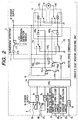
- FIG. 2 there is shown a detail configuration of a driver seat window operation unit of the power window apparatus shown in FIG. 1.
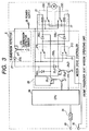
- FIG. 3 there is shown a detail configuration of a front passenger seat window operation unit of the power window apparatus shown in FIG. 1.
- the power window apparatus of this embodiment comprises a driver seat window operation unit 1, a front passenger seat window operation unit 2, a rear right seat window operation unit 3, a rear left seat window operation unit 4, a bus line 5, and three transmission lines 6 1 , 6 2 , an 6 3 .
- the driver seat window operation unit 1 comprises a driver seat window open switch 7D of 1-circuit 2-contact type, a driver seat window close switch 7U of 1-circuit 2-contact type, a front passenger seat window open/close switch 8, a rear right seat window open/close switch 9, a rear left seat window open/close switch 10, an auto switch 11, a window open/close motor 12, a motor rotational direction switching relay 13, a controller (CPU) 14, a motor drive controller 15, an interface (I/F) 16, a submersion detector 17, a power supply terminal 18, a bus line connector terminal 19, and three connection line terminals 20 1 , 20 2 , and 20 3 .
- a driver seat window open switch 7D of 1-circuit 2-contact type the driver seat window close switch 7U of 1-circuit 2-contact type
- a front passenger seat window open/close switch 8 a rear right seat window open/close switch 9, a rear left seat window open/close switch 10
- an auto switch 11 a window open/close motor 12
- a motor rotational direction switching relay 13 a controller (
- the front passenger seat window open/close switch 8 comprises a front passenger seat window close switch 8U of 1-circuit 2-contact type, a front passenger seat window open switch 8D of 1-circuit 2-contact type, and two interfaces (I/f) 8 1 and 8 2 .
- the rear right seat window open/close switch 9 and the rear left seat window open/close switch 10 have each the same configuration, although not shown in FIG. 2, as the front passenger seat window open/close switch.
- the motor rotational direction switching relay 13 comprises a window close relay 13U of 1-circuit 2-contact type and a window open relay 13D of 1-circuit 2-contact type.
- the motor drive controller 15 comprises transistors 15 1 U, 15 2 U for driving the window close relay 13U, transistors 15 1 D and 15 2 D for driving the window open relay 13D, and four buffer diodes 15D 1 , 15D 2 , 15D 3 , and 15D 4 .
- the submersion detector 17 comprises a submersion detector sensor 17S, a submersion detector transistor 17T, and one buffer diode 17D.
- the components 7D, 7U, 8 through 19, and 20 1 through 20 3 of the driver seat window operation unit are interconnected as shown in FIGS. 1 and 2.
- the front passenger seat window operation unit 2 comprises a front passenger seat window close switch 21U of 1-circuit 2-contact type, a front passenger seat window open switch 21D of 1-circuit 2-contact type, a window open/close motor 22, a motor rotational direction switching relay 23, a controller (CPU) 24, a motor drive controller 25, an interface (I/F) 26, a submersion detector 27, a power supply terminal 28, a bus line connector terminal 29, and a connection line terminal 30.
- the motor rotational direction switching relay 23 comprises a window close relay 23U of 1-circuit and 2-contact type and a window open relay 23D of 1-circuit 2-contact type.
- the motor drive controller 25 comprises transistors 25 1 U and 25 2 U for driving the window close relay 23U, transistors 25 1 D and 25 2 D for driving the window open relay 23D, and two buffer diodes 25D 1 and 25D 2 .
- the submersion detector 27 comprises a submersion detector sensor 27S, a submersion detector transistor 27T, and one buffer diode 27D.
- the components 21D, 21U, 22 through 30 of the front passenger seat window operation unit are interconnected as shown in FIG. 1 and 3.
- the rear right seat window operation unit 3 and the rear left seat window operation unit 4 have each the same circuit configuration as that of the front passenger seat window operation unit shown in FIG. 3.
- the bus line 5, as shown in FIG. 1 is connected between the bus line connection terminal 19 of the driver seat window operation unit 1, the bus line connection terminal 29 of the front passenger seat window operation unit 2, the bus line connection terminal (not shown) of the rear right seat window operation unit 3, and the bus line connection terminal (not shown) of the rear left seat window operation unit 4.
- the connection line 6 1 is connected between the connection line terminal 20 1 of the driver seat window operation unit 1 and the connection line terminal 30 of the front passenger seat window operation unit 2.
- the connection line 6 2 is connected between the connection line terminal 20 2 of the driver seat window operation unit 1 and the connection line terminal (not shown) of the rear right seat window operation unit 3.
- the connection line 6 3 is connected between the connection line terminal 20 3 of the driver seat window operation unit 1 and the connection line terminal (not shown) of the rear left seat window operation unit 4.
- the power window apparatus of this embodiment having the above-mentioned configuration operates as follows.
- the contacts of the driver seat window close switch 7U are switched from a state represented by solid line to a state represented by dashed line as shown in FIG. 2.
- a positive voltage supplied to the power supply terminal 18 is supplied to the window close relay 13U of the motor rotational direction switching relay 13 through the switched driver seat window close switch 7U and the buffer diode 15D 3 , thereby switching the contacts of the window close relay 13U from a state represented by solid line to a state represented by dashed line.
- the positive voltage at the power supply terminal 18 is supplied to the window open/close motor 12 through the contacts of the switched window close relay 13U, upon which the window open/close motor 12 rotates in the direction of closing the driver seat window connected to the motor 12.
- the contacts of the driver seat window open switch 7D are switched from a state represented by solid line to a state represented by dashed line to supply the positive voltage from the power supply terminal 18 to the window open relay 13D of the motor rotational direction switching relay 13 through the switched driver seat window open switch 7D and the buffer diode 15D 4 , thereby switching the contacts of the window open relay 13D from a state represented by solid line to a state represented by dashed line as shown in FIG. 2.
- the positive voltage at the power supply terminal 18 is supplied to the window open/close motor 12 through the switched contacts of the window open relay 13D to rotate the window open/close motor 12 in the direction of opening the driver seat window.
- the controller 14 senses this contact switching through the interface 8 1 , thereby generating a first control information signal for closing the front passenger side window.
- the first control information signal is transmitted from the controller 14 to the front passenger seat window operation unit 2 through the interface 16, the bus line connection terminal 19, and the bus line 5.
- Receiving the first control information signal at the bus line connection terminal 29, the front passenger seat window operation unit 2 supplies the received signal to the controller 24 through the interface 26.
- the controller 24 supplies a drive signal to the transistor 25 2 U to make the same conduct, which in turn makes the transistor 25 1 U conduct.
- the positive voltage at the power supply voltage 28 is supplied to the window close relay 23U of the motor rotational direction switching relay 23 through the conducting transistor 25 1 U, thereby switching the contacts of the window close relay 23U from a state represented by solid line to a state represented by dashed line as shown in FIG. 3.
- the positive voltage at the power supply terminal 28 is supplied to the window open/close motor 22 through the switched contacts of the window close relay 23U, thereby rotating the window open/close motor 22 in one direction to close the front passenger seat window.
- the driver manually operates the front passenger seat window open switch 8D of the front passenger seat window open/close switch 8 located on the driver seat window operation unit 1 to switch the contacts of the switch 8D from a state represented by solid line to a state represented by dashed line as shown in FIG. 2, the positive voltage at the power supply terminal 18 is applied to the normally close contacts of the front passenger seat window open switch 21D through the switched passenger seat window open switch 8D, the bus line connection terminal 20 1 , the connection line 6 1 , and the bus line connection terminal 30 of the front passenger seat window operation unit 2, driving the window open relay 23D through the buffer diode 25D 2 .
- the controller 14 senses this contact switching of the passenger seat window open switch 8D through the interface 8 2 , generating a second control information signal.
- the second control information signal is transmitted from the controller 14 to the front passenger seat window operation unit 2 through the interface 16, the bus line connection terminal 19, and the bus line 5.
- Receiving the second control information signal at the bus line connection terminal 29, the front passenger seat window operation unit 2 supplies this signal to the controller 24 through the interface 26.
- the controller 24 senses the operation of the front passenger seat window open switch 8D of the driver seat window operation unit 1, thereby assuming that the front passenger seat window has opened.
- the controller 14 when the driver manually operates the rear right seat window close switch (not shown) of the rear right seat window open/close switch 9 located on the driver seat window operation unit 1 to switch the contacts of the window close switch, the controller 14 generates a third control information signal for closing the rear right seat window.
- the third control information signal is supplied to the rear right passenger side window operation unit 3 through the bus line 5.
- the rear right seat window operation unit 3 operates to close the rear right seat window in generally the same sequence as when the front passenger seat window is closed by operating the front passenger seat window operation unit 2.
- the driver manually operates the rear right seat window open switch (not shown) of the rear right seat window open/close switch 9 located on the driver seat window operation unit 1 to switch the contacts of this window open switch
- the positive voltage at the power supply terminal 18 is applied to the normally close contacts (not shown) of the rear right seat window open switch of the rear right seat window operation unit 3 through the switched rear right seat window open switch, the bus line connection terminal 20 2 , the connection line 6 2 , and the bus line connection terminal (not shown) of the rear right seat window operation unit 3, thereby opening the rear right seat window in generally the same sequence as when the front passenger seat window is opened by operating the front passenger seat window operation unit 2.
- the rear left seat window open/close switch 10 located on the driver seat window operation unit 1
- the rear left seat window is opened or closed in generally the same sequence as when the rear right seat window open/close switch 9 is operated.
- the contacts of the front passenger seat window close switch 21U are switched from a state represented by solid line to a state represented by dashed line as shown in FIG. 3.
- the positive voltage at the power supply terminal 27 is supplied to the window close relay 23U of the motor rotational direction switching relay 23 through the switched front passenger seat window close switch 21U and the buffer diode 25D 1 , thereby switching the contacts of the window close relay 23U from a state represented by solid line to a state represented by dashed line as shown in FIG. 3.
- the positive voltage at the power supply terminal 28 is supplied to the window open/close motor 22 through the switched contacts of the window close relay 21U, upon which the window open/close motor 22 rotates in one direction to close the front passenger seat window.
- the contacts of the front passenger seat window open switch 21D are switched from a state represented by solid line to a state represented by dashed line as shown in FIG. 3.
- the positive voltage at the power supply terminal 28 is supplied to the window open relay 23D of the motor rotational direction switching relay 23 through the switched front passenger seat window open switch 21D and the buffer diode 25D 2 , thereby switching the contacts of the window open relay 23D from a state represented by solid line to a state represented by dashed line as shown in FIG. 3.
- the positive voltage at the power supply terminal 28 is supplied to the window open/close motor 22 through the switched window open relay 21D, upon which the window open/close motor rotates in the direction of opening the front passenger seat window.
- the rear right side window or the rear left side window is closed in generally the same sequence as when the front passenger operates the front passenger seat window close switch 21U located on the front passenger seat window operation unit 2.
- the rear right seat window or the rear left seat window is opened in generally the same sequence as when the front passenger manually operates the front passenger seat window open switch 21D located on the front passenger seat window operation unit 2.
- the submersion detector sensor 17S of the submersion detector 17 of the driver seat window operation unit 1 does not detect submersion and a terminal-to-terminal resistance of the submersion detector sensor 17S is large enough to put the submersion detection transistor 17T in a nonconducting state. Therefore, no submersion detection signal is outputted from the submersion detector 17.
- the following describes the operation of the power window apparatus of the present embodiment to be executed when the automobile has been submerged for some reason and the automobile is flooded inside.
- the driver seat door pocket, the front passenger seat door pocket, the rear right seat door pocket, and the rear left seat door pocket are also flooded to put the driver seat window operation unit 1, the front passenger seat window operation unit 2, the rear right seat window operation unit 3, and the rear left seat window operation unit 4 into the flooded state.
- the submersion detector 17 When the submersion detector sensor 17S exposed from the submersion detector 17 of the driver seat window operation unit 1 detects flooding soon after the flooding inside the automobile, the submersion detector 17 outputs a submersion detection signal.
- the resistance between these conductors lowers to make lower the base circuit in a direct current manner of the submersion detection transistor 17T, thereby making the same conduct, upon which a submersion detection signal based on a direct-current voltage value approximate to the supply voltage at the power supply terminal 18 is outputted from the submersion detector 17. Then, the outputted submersion detection signal is supplied to the motor drive controller 15 of the driver seat window operation unit 1.
- the submersion detection signal supplied to the motor drive controller 15 is then supplied to the window open relay 13D and the window close relay 13U of the motor rotational direction switching relay 13 through the buffer diodes 15D 1 and 15D 2 , thereby switching the contacts of the window open relay 13D from a state represented by solid line to a state represented by dashed line as shown in FIG. 2 and contacts of the window close relay 13U from a state represented by solid line to a state represented by dashed line as shown in FIG. 2.
- the supply voltage is applied from the power supply terminal 18 between both the ends of the window open/close motor 12, so that the window open/close motor 5 does not rotate in either direction. Consequently, the driver seat window is neither opened nor closed.
- the contacts of the switch 7D are switched from a state represented by solid line to a state represented by dashed line as shown in FIG. 2, supplying the positive voltage from the power supply terminal 18 to both ends of the window close relay 13U.
- the operation of the window close relay 13U is stopped, the contact thereof being restored from the state represented by dashed line to the state represented by solid line, upon which the contact-side terminal of the window close relay 13U of the window open/close motor 12 is grounded.
- the contacts of the switch 8D are switched from the state represented by dashed line to the state represented by solid line as shown in FIG. 2 to output a front passenger seat window open signal based on the voltage supplied from the power supply terminal 18 to the connection line 6 1 of the connection line terminal 20 1 , the signal being transmitted to the front passenger seat window operation unit 2 through the connection line 6 1 .
- the front passenger seat window operation unit 2 supplies this signal to the normally close contacts of the front passenger seat window open switch 21D.
- the front passenger seat window open signal is supplied to the window open relay 23D through the contacts switched to the state represented by solid line as shown in FIG. 3, thereby switching these contacts from the state represented by solid line to the state represented by dashed line as shown in FIG. 3.
- This supplies the supply voltage from the power supply terminal 27 to both ends of the window open/close motor 22 through the contacts of the window open relay 23D, thereby rotating the window open/close motor 22 in the direction of opening the front passenger seat window. This allows the front passenger to escape from the submerged automobile through the opened front passenger seat window.
- the submersion detector 27 senses the flooding and outputs a submersion detection signal to the motor drive controller 25, thereby providing anti-submersion measures on the front passenger seat window operation unit 2.
- the application of water between the pair of submersion detection conductors of the submersion detector sensor 27S exposed from the submersion detector 27 reduces the resistance between the pair of submersion detection conductors, which in turn linearly reduces the resistance of the base circuit of the submersion detection transistor 27T to make the same conduct, thereby outputting from the submersion detector 27 a submersion detection signal generally equal to the supply voltage at the power supply terminal 28 to the motor drive controller 25.
- the submersion detection signal supplied to the motor drive controller 25 is supplied to the window open relay 23D and the window close relay 23U of the motor rotational direction switching relay 23 through the buffer diodes 25D 1 and 25D 2 , simultaneously switching the contacts of the window open relay 23D and the contacts of the window close relay 23U from the state represented by solid line to the state represented by dashed line as shown in FIG. 2.
- This arrangement also provides anti-submersion measures for the front passenger seat window operation unit 2.
- a front passenger seat window open signal is supplied to the front passenger seat window operation unit 2 through the connection line 6 1 .
- This signal is then supplied to the normally close contacts of the front passenger seat window open switch 21D and then to the normally close contacts of the window close relay 23U and the window open relay 23D. Consequently, the supply voltage is applied to both ends of the window close relay 23U to stop the operation of the window close relay 23U while the operation of the window open relay 23D continues operating, thereby rotating the window open/close motor in the direction of opening the front passenger seat window.
- a rear right seat window open signal based on the supply voltage from the power supply terminal 18 is outputted to the connection line terminal 20 2 , the signal being further transmitted to the rear right seat window operation unit 3 through the connection line 6 2 .
- the operation to be executed in the rear right seat window operation unit 3 is generally the same as that in the front passenger seat window operation unit 2 and therefore the description will be skipped.
- a rear left seat window open signal based on the supply voltage from the power supply terminal 18 is outputted to the connection line terminal 203, the signal being further transmitted to the rear left seat window operation unit 4 through the connection line 6 3 .
- the operation to be executed in the rear right seat window operation unit 4 is generally the same as that in the front passenger seat window operation unit 2 and therefore the description will be skipped.
- the submersion detector sensor 17S of the submersion detector 17 in the driver seat window operation unit 1 senses the flooding and the submersion detector 17 outputs a submersion detection signal, this signal is supplied to the motor drive controller 15 in the driver seat window operation unit 1.
- the driver manually operates the driver seat window open switch 7D, the driver seat window can be opened.
- the window open switch 8D of the front passenger seat window open/close switch 8 the window open switch of the rear right seat window open/close switch 9, and the window open switch of the rear left seat window open/close switch 10 located on the driver seat window operation unit 1
- the front passenger seat window, the rear right seat window, and the rear left seat window can be opened. Passengers can then escape from the submerged automobile through the opened windows respectively.
- the front passenger seat window open signal, the rear right seat window open signal, and rear left seat window open signal are supplied in the form of direct current electrical signals from the driver seat window operation unit 1 to the front passenger seat window operation unit 2, the rear right seat window operation unit 3, and the rear left seat window operation unit 4 through the connection lines 6 1 , 6 2 , and 6 3 respectively.
- This arrangement simplifies the configuration of the apparatus and enhances its operational reliability.
- the description of the above-mentioned embodiment has been made by use of an example in which the submersion detectors 17 and 27 are located on the driver seat window operation unit 1 and the front passenger seat window operation unit 2. It will be apparent to those skilled in the art that the submersion detectors according to the invention may also be provided in one or more of the passenger seat window operation units other than the driver seat window operation unit 1 as required.
- the submersion detector located on the driver seat window operation unit senses the flooding and supplies a submersion detection signal to the drive controller located on the driver seat window operation unit.
- the driver manually operates one or more window open switches located on the driver seat window operation unit, one or more corresponding windows are immediately opened, through which the driver and/or one or more passengers can escape from the submerged automobile.
- the window open signals based on a direct current voltage are transmitted from the driver seat window operation unit to the passenger seat window operation units through connection lines, thereby simplifying the configuration of the power window apparatus and enhances its operational reliability.
Landscapes
- Engineering & Computer Science (AREA)
- Mechanical Engineering (AREA)
- Power-Operated Mechanisms For Wings (AREA)
- Window Of Vehicle (AREA)
Applications Claiming Priority (2)
| Application Number | Priority Date | Filing Date | Title |
|---|---|---|---|
| JP5268999A JP3597072B2 (ja) | 1999-03-01 | 1999-03-01 | パワーウインド装置 |
| JP5268999 | 1999-03-01 |
Publications (3)
| Publication Number | Publication Date |
|---|---|
| EP1033464A2 true EP1033464A2 (de) | 2000-09-06 |
| EP1033464A3 EP1033464A3 (de) | 2005-08-10 |
| EP1033464B1 EP1033464B1 (de) | 2013-07-17 |
Family
ID=12921869
Family Applications (1)
| Application Number | Title | Priority Date | Filing Date |
|---|---|---|---|
| EP00104159.9A Expired - Lifetime EP1033464B1 (de) | 1999-03-01 | 2000-02-29 | Motorisch angetriebener Fensterheber mit Fähigkeit zum Offnen beliebiger Fenster durch Betätigen der korrespondierenden Taste von Fahrersitz-Fensterbetätigungseinheit bei Erkennung einer Uberflutung im Fahrzeuginnenraum |
Country Status (4)
| Country | Link |
|---|---|
| US (1) | US6278250B1 (de) |
| EP (1) | EP1033464B1 (de) |
| JP (1) | JP3597072B2 (de) |
| KR (1) | KR100365821B1 (de) |
Cited By (4)
| Publication number | Priority date | Publication date | Assignee | Title |
|---|---|---|---|---|
| DE10236106A1 (de) * | 2002-08-07 | 2004-02-19 | Brose Fahrzeugteile Gmbh & Co. Kommanditgesellschaft, Coburg | Verfahren und Sicherungssystem für eine Verstelleinrichtung eines Kraftfahrzeugs |
| DE102004007328A1 (de) * | 2004-02-14 | 2005-09-01 | Leopold Kostal Gmbh & Co Kg | Elektrische Schaltungsanordnung |
| CN102452299A (zh) * | 2010-10-14 | 2012-05-16 | 欧姆龙汽车电子株式会社 | 车辆用窗户开闭控制装置 |
| CN104908558A (zh) * | 2014-03-14 | 2015-09-16 | 欧姆龙汽车电子株式会社 | 窗开闭控制系统以及窗开闭控制装置 |
Families Citing this family (12)
| Publication number | Priority date | Publication date | Assignee | Title |
|---|---|---|---|---|
| JP3756718B2 (ja) * | 2000-01-17 | 2006-03-15 | アルプス電気株式会社 | 耐水性パワーウインド装置 |
| JP3760792B2 (ja) * | 2001-05-11 | 2006-03-29 | 株式会社デンソー | 水没センサ付きパワーウインドウ装置 |
| US6483267B1 (en) * | 2001-09-27 | 2002-11-19 | John K. Jurney | Auxiliary vehicular window recessing system |
| JP3896292B2 (ja) * | 2002-02-14 | 2007-03-22 | アルプス電気株式会社 | 水没対応開閉体駆動回路 |
| TW530788U (en) * | 2002-05-30 | 2003-05-01 | Sin Etke Technology Co Ltd | Vehicular alarming device for outside water level |
| US20060006701A1 (en) * | 2004-07-06 | 2006-01-12 | Jason Wells | System and method for rain detection and automatic operation of power roof and power windows |
| KR100680837B1 (ko) * | 2005-11-11 | 2007-02-08 | 기아자동차주식회사 | 자동차용 파워 윈도우의 안전 개폐 시스템 |
| US7861460B1 (en) * | 2007-12-12 | 2011-01-04 | Anthony Costello | Emergency window opening system |
| JP4513864B2 (ja) * | 2008-01-23 | 2010-07-28 | 株式会社デンソー | 電子制御装置 |
| JP5936269B2 (ja) * | 2012-09-12 | 2016-06-22 | オムロンオートモーティブエレクトロニクス株式会社 | 車両の窓開閉制御装置 |
| JP6012569B2 (ja) * | 2013-09-11 | 2016-10-25 | オムロンオートモーティブエレクトロニクス株式会社 | 車両用パワーウインドウ装置 |
| JP6066342B2 (ja) * | 2014-07-03 | 2017-01-25 | オムロンオートモーティブエレクトロニクス株式会社 | 窓開閉制御システム及び窓開閉制御装置 |
Citations (1)
| Publication number | Priority date | Publication date | Assignee | Title |
|---|---|---|---|---|
| JPH10309938A (ja) | 1997-05-08 | 1998-11-24 | Jidosha Denki Kogyo Co Ltd | 車両用窓開閉装置 |
Family Cites Families (11)
| Publication number | Priority date | Publication date | Assignee | Title |
|---|---|---|---|---|
| JP2674838B2 (ja) * | 1989-08-23 | 1997-11-12 | アスモ株式会社 | ウインドガラス昇降装置及びウインド駆動用モータ |
| JPH07230736A (ja) | 1994-02-18 | 1995-08-29 | Shigetoshi Matsuzuka | 加圧導電自動スイッチ |
| JPH08203399A (ja) | 1994-02-28 | 1996-08-09 | Shigetoshi Matsuzuka | 圧力差スイッチ |
| KR19990002949A (ko) * | 1997-06-24 | 1999-01-15 | 유기범 | Atm 교환기에 있어서 제어계 구성방법 |
| JP3269991B2 (ja) * | 1997-07-22 | 2002-04-02 | 本田技研工業株式会社 | パワーウインドウの駆動回路 |
| JP3759293B2 (ja) * | 1997-08-08 | 2006-03-22 | 本田技研工業株式会社 | パワーウインドウの駆動回路 |
| JP3427205B2 (ja) * | 1997-08-18 | 2003-07-14 | 東洋電装株式会社 | パワーウインド装置 |
| DE69822412T2 (de) * | 1997-12-05 | 2005-03-03 | Alps Electric Co., Ltd. | Wasserdichte elektrische Fensterhebevorrichtung |
| DE69906402T2 (de) * | 1998-01-23 | 2003-10-30 | Alps Electric Co., Ltd. | Fensterheberantriebsvorrichtung und Steuervorrichtung dafür |
| JP3479737B2 (ja) * | 1998-04-09 | 2003-12-15 | 東洋電装株式会社 | パワーウインド装置 |
| JP2000154682A (ja) * | 1998-11-20 | 2000-06-06 | Fuji Heavy Ind Ltd | パワーウインド装置 |
-
1999
- 1999-03-01 JP JP5268999A patent/JP3597072B2/ja not_active Expired - Fee Related
-
2000
- 2000-02-28 US US09/514,690 patent/US6278250B1/en not_active Expired - Lifetime
- 2000-02-29 EP EP00104159.9A patent/EP1033464B1/de not_active Expired - Lifetime
- 2000-02-29 KR KR1020000009996A patent/KR100365821B1/ko not_active Expired - Fee Related
Patent Citations (1)
| Publication number | Priority date | Publication date | Assignee | Title |
|---|---|---|---|---|
| JPH10309938A (ja) | 1997-05-08 | 1998-11-24 | Jidosha Denki Kogyo Co Ltd | 車両用窓開閉装置 |
Cited By (9)
| Publication number | Priority date | Publication date | Assignee | Title |
|---|---|---|---|---|
| DE10236106A1 (de) * | 2002-08-07 | 2004-02-19 | Brose Fahrzeugteile Gmbh & Co. Kommanditgesellschaft, Coburg | Verfahren und Sicherungssystem für eine Verstelleinrichtung eines Kraftfahrzeugs |
| US7550867B2 (en) | 2002-08-07 | 2009-06-23 | Brose Fahrzeugteile Gmbh & Co Kg | Method and safety system for a displacement device of a motor vehicle |
| DE102004007328A1 (de) * | 2004-02-14 | 2005-09-01 | Leopold Kostal Gmbh & Co Kg | Elektrische Schaltungsanordnung |
| US7282817B2 (en) | 2004-02-14 | 2007-10-16 | Leopold Kostal Gmbh & Co. Kg | Electrical circuit arrangement for controlling an electromotor in a motor vehicle |
| CN102452299A (zh) * | 2010-10-14 | 2012-05-16 | 欧姆龙汽车电子株式会社 | 车辆用窗户开闭控制装置 |
| US8710773B2 (en) | 2010-10-14 | 2014-04-29 | Omron Automotive Electronics Co., Ltd. | Vehicle window opening and closing control device |
| CN102452299B (zh) * | 2010-10-14 | 2015-04-22 | 欧姆龙汽车电子株式会社 | 车辆用窗户开闭控制装置 |
| CN104908558A (zh) * | 2014-03-14 | 2015-09-16 | 欧姆龙汽车电子株式会社 | 窗开闭控制系统以及窗开闭控制装置 |
| CN104908558B (zh) * | 2014-03-14 | 2017-05-31 | 欧姆龙汽车电子株式会社 | 窗开闭控制系统以及窗开闭控制装置 |
Also Published As
| Publication number | Publication date |
|---|---|
| EP1033464B1 (de) | 2013-07-17 |
| EP1033464A3 (de) | 2005-08-10 |
| JP2000248832A (ja) | 2000-09-12 |
| US6278250B1 (en) | 2001-08-21 |
| JP3597072B2 (ja) | 2004-12-02 |
| KR20000062668A (ko) | 2000-10-25 |
| KR100365821B1 (ko) | 2002-12-26 |
Similar Documents
| Publication | Publication Date | Title |
|---|---|---|
| US6278250B1 (en) | Power window apparatus capable of opening windows at operation side by manually operating driver seat window open switch or passenger seat window open switch located on driver seat window operation unit upon detection of flooding inside automobile | |
| US6281647B1 (en) | Power window apparatus | |
| US6690096B2 (en) | Submergence-detecting power-window apparatus | |
| JP3684328B2 (ja) | パワーウインド装置 | |
| US6031296A (en) | Power window apparatus | |
| JP3756718B2 (ja) | 耐水性パワーウインド装置 | |
| JP2711248B2 (ja) | 自動車の1以上の電気負荷用の回路装置 | |
| JP2022127157A (ja) | パワーウィンドウ装置 | |
| US6975084B2 (en) | Power window controller | |
| US6009362A (en) | Anomalous condition detecting apparatus for cooling motor fan | |
| US6111326A (en) | Control circuit for opening/closing device in a vehicle | |
| JP3602978B2 (ja) | 水没検知パワーウインド装置 | |
| EP0451825A1 (de) | Vielfach-Übertragungsverfahren und System für ein Fahrzeug | |
| US6965207B2 (en) | Power window apparatus | |
| KR100370686B1 (ko) | 파워윈도우장치 | |
| JP2950159B2 (ja) | スライドドア用給電システム | |
| JP3555340B2 (ja) | 挟み込み検知装置及びパワーウインドウ装置 | |
| JP4041981B2 (ja) | 駆動装置 | |
| JPS61226678A (ja) | 閉成部材の開閉装置の安全装置 | |
| JPH07156726A (ja) | スライドドア用給電システム | |
| JPH11280335A5 (de) | ||
| JP2010159012A (ja) | パワーウインドウ制御ユニット及びパワーウインドウ制御システム | |
| JP2002136166A (ja) | パワーウインドウ装置 | |
| JP2002106228A (ja) | 車両用電動機器のコントローラシステム | |
| JPH10119565A (ja) | 動力付窓開閉装置 |
Legal Events
| Date | Code | Title | Description |
|---|---|---|---|
| PUAI | Public reference made under article 153(3) epc to a published international application that has entered the european phase |
Free format text: ORIGINAL CODE: 0009012 |
|
| AK | Designated contracting states |
Kind code of ref document: A2 Designated state(s): AT BE CH CY DE DK ES FI FR GB GR IE IT LI LU MC NL PT SE |
|
| AX | Request for extension of the european patent |
Free format text: AL;LT;LV;MK;RO;SI |
|
| RIN1 | Information on inventor provided before grant (corrected) |
Inventor name: SASAKI, AKIRA |
|
| PUAL | Search report despatched |
Free format text: ORIGINAL CODE: 0009013 |
|
| AK | Designated contracting states |
Kind code of ref document: A3 Designated state(s): AT BE CH CY DE DK ES FI FR GB GR IE IT LI LU MC NL PT SE |
|
| AX | Request for extension of the european patent |
Extension state: AL LT LV MK RO SI |
|
| RIC1 | Information provided on ipc code assigned before grant |
Ipc: 7E 05F 15/00 B Ipc: 7E 05F 15/16 A Ipc: 7B 60J 1/17 B |
|
| 17P | Request for examination filed |
Effective date: 20050901 |
|
| AKX | Designation fees paid |
Designated state(s): DE FR GB NL |
|
| 17Q | First examination report despatched |
Effective date: 20071227 |
|
| GRAP | Despatch of communication of intention to grant a patent |
Free format text: ORIGINAL CODE: EPIDOSNIGR1 |
|
| GRAS | Grant fee paid |
Free format text: ORIGINAL CODE: EPIDOSNIGR3 |
|
| GRAA | (expected) grant |
Free format text: ORIGINAL CODE: 0009210 |
|
| AK | Designated contracting states |
Kind code of ref document: B1 Designated state(s): DE FR GB NL |
|
| REG | Reference to a national code |
Ref country code: GB Ref legal event code: FG4D |
|
| REG | Reference to a national code |
Ref country code: DE Ref legal event code: R096 Ref document number: 60048127 Country of ref document: DE Effective date: 20130912 |
|
| REG | Reference to a national code |
Ref country code: NL Ref legal event code: VDEP Effective date: 20130717 |
|
| PG25 | Lapsed in a contracting state [announced via postgrant information from national office to epo] |
Ref country code: NL Free format text: LAPSE BECAUSE OF FAILURE TO SUBMIT A TRANSLATION OF THE DESCRIPTION OR TO PAY THE FEE WITHIN THE PRESCRIBED TIME-LIMIT Effective date: 20130717 |
|
| PLBE | No opposition filed within time limit |
Free format text: ORIGINAL CODE: 0009261 |
|
| STAA | Information on the status of an ep patent application or granted ep patent |
Free format text: STATUS: NO OPPOSITION FILED WITHIN TIME LIMIT |
|
| 26N | No opposition filed |
Effective date: 20140422 |
|
| REG | Reference to a national code |
Ref country code: DE Ref legal event code: R097 Ref document number: 60048127 Country of ref document: DE Effective date: 20140422 |
|
| GBPC | Gb: european patent ceased through non-payment of renewal fee |
Effective date: 20140228 |
|
| REG | Reference to a national code |
Ref country code: FR Ref legal event code: ST Effective date: 20141031 |
|
| PG25 | Lapsed in a contracting state [announced via postgrant information from national office to epo] |
Ref country code: FR Free format text: LAPSE BECAUSE OF NON-PAYMENT OF DUE FEES Effective date: 20140228 Ref country code: GB Free format text: LAPSE BECAUSE OF NON-PAYMENT OF DUE FEES Effective date: 20140228 |
|
| PGFP | Annual fee paid to national office [announced via postgrant information from national office to epo] |
Ref country code: DE Payment date: 20150227 Year of fee payment: 16 |
|
| REG | Reference to a national code |
Ref country code: DE Ref legal event code: R119 Ref document number: 60048127 Country of ref document: DE |
|
| PG25 | Lapsed in a contracting state [announced via postgrant information from national office to epo] |
Ref country code: DE Free format text: LAPSE BECAUSE OF NON-PAYMENT OF DUE FEES Effective date: 20160901 |