EP1032128A1 - Méthode de traitement de données de transmetteur et de programme dans un récepteur FM RDS - Google Patents
Méthode de traitement de données de transmetteur et de programme dans un récepteur FM RDS Download PDFInfo
- Publication number
- EP1032128A1 EP1032128A1 EP99200527A EP99200527A EP1032128A1 EP 1032128 A1 EP1032128 A1 EP 1032128A1 EP 99200527 A EP99200527 A EP 99200527A EP 99200527 A EP99200527 A EP 99200527A EP 1032128 A1 EP1032128 A1 EP 1032128A1
- Authority
- EP
- European Patent Office
- Prior art keywords
- rds
- transmitter
- data
- memory bank
- tuning
- Prior art date
- Legal status (The legal status is an assumption and is not a legal conclusion. Google has not performed a legal analysis and makes no representation as to the accuracy of the status listed.)
- Withdrawn
Links
Images


Classifications
-
- H—ELECTRICITY
- H03—ELECTRONIC CIRCUITRY
- H03J—TUNING RESONANT CIRCUITS; SELECTING RESONANT CIRCUITS
- H03J1/00—Details of adjusting, driving, indicating, or mechanical control arrangements for resonant circuits in general
- H03J1/0008—Details of adjusting, driving, indicating, or mechanical control arrangements for resonant circuits in general using a central processing unit, e.g. a microprocessor
- H03J1/0058—Details of adjusting, driving, indicating, or mechanical control arrangements for resonant circuits in general using a central processing unit, e.g. a microprocessor provided with channel identification means
- H03J1/0083—Details of adjusting, driving, indicating, or mechanical control arrangements for resonant circuits in general using a central processing unit, e.g. a microprocessor provided with channel identification means using two or more tuners
-
- H—ELECTRICITY
- H04—ELECTRIC COMMUNICATION TECHNIQUE
- H04H—BROADCAST COMMUNICATION
- H04H2201/00—Aspects of broadcast communication
- H04H2201/10—Aspects of broadcast communication characterised by the type of broadcast system
- H04H2201/13—Aspects of broadcast communication characterised by the type of broadcast system radio data system/radio broadcast data system [RDS/RBDS]
Definitions
- the invention relates to a method for processing transmitter and program related data in an FM RDS receiver and to a receiver executing the method.
- the FM RDS broadcasting standard is defined in Specification of the Radio Data System FM RDS for VHF-FM Sound Broadcasting' by the European Broadcasting Union (EBU), EBU document Tech 3244-E, March 1984 and updated in subsequent revisions thereof. Reference is made to this document for a correct understanding of the meaning and definition of the various terms and abbreviations used hereinafter in connection with the FM RDS standard.
- EBU European Broadcasting Union
- An FM RDS receiver executing the above method is on itself known e.g. from European Patent 0 333 194.
- the known FM receiver is a dual tuner FM RDS receiver having a first or main tuner and a second or auxiliary tuner.
- the main tuner is used to tune the receiver to a broadcast transmitter station with a wanted audio program and to process the audio program signals for sound reproduction. If the transmitter transmits RDS data as well, then the main tuner will also extract the RDS data carried by the received RDS transmitter signal, in particular a list of alternative frequencies (AFs). Such list provide tuning data of transmitter frequencies carrying the same program as the one the receiver is actually tuned to.
- the auxiliary tuner is used to monitor the reception quality of the transmitter signals at each of those AFs.
- the auxiliary tuner is sequentially switched to each AF in the AF list to measure the reception quality of the transmitter signals at the respective AFs.
- This reception quality information is stored in a memory and continuously updated in sequential scan cycles.
- the main tuner is automatically switched over in its tuning to the AF stored in the memory having highest reception quality.
- a method for processing transmitter and program related data in an FM RDS receiver is therefore characterized by a band scanning search for detecting FM RDS transmitters exceeding a predetermined reception quality level, by storing in a first memory bank transmitter related data per each such transmitter, including the tuning data and a quality factor indicating the quality in reception thereof, by storing in a second memory bank program related FM RDS data per each received program identification code and by allocating to the transmitter data of each FM RDS transmitter stored in the first memorybank a linkage code defining the storage address within the second memory bank containing the program data carried by the relevant FM RDS transmitter.
- the second tuner is used to scan sequentially through the frequency band to search for any broadcasting transmitter station received with adequate RF signal reception quality, including FM RDS broadcast stations. Upon detection of such FM broadcasting transmitter station, the scanning is stopped to read the above transmitter related data into the first memory bank and in case of an FM RDS signal to read the FM RDS data into the second memory bank as well.
- the splitting in the storage of the transmitter related data and the program related data allows to make efficient use of storage capacity while preserving any tuning selection option for the user as will hereinafter be explained in more detail.
- the storage of RDS program data allows e.g. to provide AF switching without making use of the AF lists included in the RDS data and/or to extend the definition of alternative programs from strictly identical audio programs to non-identical programs within a certain RDS program category, such as PTY.
- An FM RDS receiver executing the method according to the invention comprising first and second tuner circuits for receiving and processing respectively audio signals and FM RDS data, comprising tuning control means to vary the tuning frequency of the second tuner circuit over a frequency band to detect FM RDS transmitters received with a reception quality exceeding a predetermined quality threshold level, the first tuner circuit automatically switching over in its tuning from an actually received first FM RDS transmitter to a second FM RDS transmitter detected by the second tuner circuit when the reception quality of the first FM RDS transmitter decreases below a predetermined level characterized by a processing unit storing in a first memory bank per each selected FM RDS transmitter, transmitter related data including the tuning data and a quality factor indicating the reception quality thereof and in a second memory bank program related FM RDS data per each received program identification code and by allocating to the transmitter data of each FM RDS transmitter stored in the first memory bank a linkage code defining the storage address within the second memory bank containing the program data carried by the relevant FM RDS transmitter.
- the method is characterized in that the band scanning search is being repeated in subsequent scan cycles, the transmitter related data being updated with regard to its quality factor and being deleted from the first memory bank when the quality factor decreases below a predetermined quality threshold level.
- An FM RDS receiver executing said preferred method is characterized in that the tuning control means controls the tuning of the second tuning circuit to repeat the band scanning search in subsequent scan cycles to update the quality factor of each detected transmitter, the storage locations in the first memory bank relating to transmitters decreasing in quality factor below a predetermined quality threshold level, being deleted.
- This measure further improves the efficiency in the use of memory capacity without losing the information which transmitter frequency should be chosen in case the actually received transmitter signal decreases below said predetermined threshold level.
- a further preferred method is characterized by an automatic tuning switch over from a first FM RDS transmitter to a second FM RDS transmitter, when the first FM RDS transmitter signal decreases below a predetermined threshold fieldstrength level, the second FM RDS transmitter being selected from the FM RDS transmitters in the first memory bank having the same linkage code as the first FM RDS transmitter.
- a embodiment of an FM RDS receiver executing the lastmentioned further preferred method is characterized in that in selecting the second transmitter the processing unit is limited to FM RDS transmitters having the same linkage code as the first FM RDS transmitter signal.
- the alternative frequencies i.e. the transmitter frequencies carrying the same audio program as the one the first tuner circuit is actually tuned to, are not derived from the AF list included in the FM RDS data, but from those transmitter having the same linkage code attached thereto.
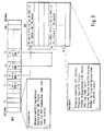
- FIG. 1 shows the FM RDS baseband coding structure in the data format of the FM RDS Group type OA as more specifically defined in the abovementioned EBU document.
- the OA Group type is to provide basic tuning and switching information and like other Group types consists of four blocks B1-B4, each containing a 16 bit information carrying part and a 10 bits checkword and offset part, respectively C1-C4.
- the checkword and offset parts C1-C4 provide error protection and block and group synchronization information.
- the information carrying parts of blocks B1-B4 respectively comprise:
- the FM RDS standard provides for a Group type OB, which differs from the Group type OA in that in block 3 the PI code is repeated.
- FIG. 2 shows a blockdiagram of an FM RDS receiver according to the invention, which coupled to an antenna 1 comprises first and second tuner circuits 2 and 3 for processing respectively audio signals and FM RDS data.
- the tuning frequency of both first and second tuner circuits 2 and 3 are controlled through tuning control means 10, 11, 25 including a central processing unit (CPU) 25 and an I/O control module 11 of a microprocessor 12 and a control bus 10.
- tuning control means 10, 11, 25 including a central processing unit (CPU) 25 and an I/O control module 11 of a microprocessor 12 and a control bus 10.
- the tuning frequency of the first tuner circuit 2 can be set through a user interface I/O module 20 to the transmitter frequency ft of a wanted FM broadcast station.
- Key 21 is to activate an autostore functionality
- key 22 is to activate an up/down search
- key 23 is to switch on/off the reception of traffic messages
- key 24 is to activate a search for programs within the same PTY category as the one actually received.
- These functionalities require the use of a program memory 26 for the storage of program software and a timer module 28 and are on themselves already known from the prior art FM RDS receiver cited hereinafter.
- the first tuner circuit 2 provides for the selection and demodulation of a wanted RF FM broadcast signal into baseband and comprises means (not shown) to measure the reception quality of the received FM RF signal.
- a quality factor reflecting said reception quality is supplied via a quality level line 14 to an AD converter module 15 of the microprocessor 12 to be further processed as described hereinafter.
- the baseband signal may comprise an RDS signal and/or a mono or stereomultiplex signal.
- the baseband signal is supplied via a signal line 5 from an output of the first tuner circuit 2 to a digital signal processor 6.
- the digital signal processor 6 comprises audio signal processing means (not shown) to process mono audio signals and eventually to demultiplex stereomultiplex signals into stereo left and right audio signals and is coupled to an audio amplifier 8 and loudspeaker set 9 for reproduction of the so derived audiosignals.
- the digital signal processor 6 is coupled to an RDS decoder 7 to decode RDS data contained in the received FM broadcast signal.
- the decoded RDS data is supplied via an RDS data line 18 to an RDS data I/O module 19 of the microprocessor 12.
- RDS data processing occurs under control of the CPU 25 of the microprocessor 12.
- the second tuner circuit 3 is used to select and demodulate RDS signals from an RF FM broadcast signal and is therefore also indicated as data tuner.
- An RDS decoder 4 following the output of the second tuner circuit 3 derives RDS data from the demodulated RDS signal.
- the RDS data is supplied via an RDS data line 16 to an RDS data I/O module 17 of the microprocessor 12.
- the second tuner 3 also comprises means (not shown) to measure the reception quality of the received RF FM broadcast signal.
- a quality factor reflecting said reception quality is supplied via a quality level line 13 to the AD converter module 15 of the microprocessor 12 for an adequate processing and storage thereof.
- the tuning frequency of the second tuner circuit 3 is automatically varied to scan over the RF FM broadcast reception band ranging from 87.5 MHz to 108 MHz.
- the scanning is stopped to make measurement and storage operations under control of the CPU 25, as described in the following with reference to Figure 3:
- the data stored in the first memory bank M1 are typically transmitter related and together form a list in a transmitter structure, hereinafter also indicated as transmitter list.
- the data stored in the second memory bank M2 are typically program or network related and together form a list in a PI-structure, hereinafter also indicated as program data or network list.
- Parameters for the quality factor may include fieldstrength, but also (lack of) multipath and other environmental sources of pollution and the above predetermined threshold level is chosen such, that RF FM broadcast signals exceeding this level can be processed properly without giving rise to receiver malfunctioning and/or noticeable signal distortions.
- the quality factor is derived from the fieldstrength of the RF reception signal, for fx being indicated with sx.
- the storage of transmitter related data in the first memory bank M1 separated from the storage of program or network related data in the second memory bank M2 allows for an efficient use of memory capacity, because transmitters carrying the same PI code share the same storage address in M2.
- all related other RDS codes such as e.g. PTY-, TA-, TMC-codes, are stored only once.
- said separation in storage also allows for efficient data processing, in particular for the purpose of an AF search, i.e. finding an alternative frequency carrying the same RDS program as the one the first tuner circuit 2 is actually tuned to.
- the second memory bank M2 can be excluded from the AF search operation.
- the AF functionality requires that the AF having highest reception quality (fh) should be known any time in order to be able to automatically switch over the tuning of the first tuner circuit 2 from an RDS transmitter ft, the first tuner circuit 2 is actually tuned, to said fh, when the reception quality of ft decreases below the above predetermined threshold quality level st.
- the use of linkage codes in searching AFs in accordance with the invention removes the necessity to decode and store the AF data transmitted in block 3 of the above RDS Group type OA.
- the tuning selection options based on reception quality are all preserved. For instance, by activating the 'autostore' option with key 21, the quality factors of the various transmitters stored in the first memory bank M1 may be compared with a certain threshold level, chosen such that it is exceeded by e.g. 6 transmitters, which can be RDS- or non-RDS transmitters.
- the tuning data of these transmitters are to be stored under the autostore feature and called upon by operating the key 21.
- the quality factor s may be used. This is also applies to the determination of a threshold level for use in the up/down search of transmitters, which can be activated with key 22.
- the tuning selection options based on these RDS data are all preserved too. For instance, the availability of PTY-codes allows to make a conventional search for PTY transmitters, which can be activated with key 24.
- the receiver can also be set to reproduce traffic messages by an operation of key 23.
- the transmitter received strongest i.e. with highest fieldstrength is in practise nearest to the receiver location and the traffic messages of that transmitter are therewith most relevant to the user.
- FIG. 4 shows a flowchart of an algorithm implementing a method for tuning the reception of radio broadcast signals to an FM RDS transmitter using program related data and transmitter related data in accordance with the invention, in which references are made to Figure 3. Steps al-a30 of this flowchart have the following meaning:
- the method applied in the above algorithm uses the RDS flag NW to keep the storage of RDS data in the second memory bank M2 carried by a detected RDS transmitter on hold, until storage capacity in M2 becomes available.
- the RDS flag NW can be dispensed with, if M2 provides sufficient storage capacity to store all receivable PI codes.
- the tuning control means providing repetitions of search scan cycles, the measurement of the reception quality and the derivation of a quality factor therefrom, the selection/detection of adequately receivable transmitters, the extraction of various categories RDS data from the received RDS signals, the storage of the transmitter and program related data in M1 and M2, the switching in the tuning of the first tuner circuit 2 to an alternative frequency, etc., etc..
- the FM RDS radio receiver type VDO RC 959 RDS for further details in this respect, reference is made to the FM RDS radio receiver type VDO RC 959 RDS.
- the invention may well be applied while excluding any historical influence from the determination of the quality factor e.g. by using the momentary value of the reception quality as a basis for the quality factor.
- the invention requires the first and second memory banks M1 and M2 to be organized to function as separate storage means, allowing M1 and M2 to be physically comprised in one memory or spread over several storage devices, dependent on the programming of the CPU 25.
Priority Applications (6)
| Application Number | Priority Date | Filing Date | Title |
|---|---|---|---|
| EP99200527A EP1032128A1 (fr) | 1999-02-23 | 1999-02-23 | Méthode de traitement de données de transmetteur et de programme dans un récepteur FM RDS |
| DE60019502T DE60019502T2 (de) | 1999-02-23 | 2000-02-11 | Verfahren zur verarbeitung von auf sender und program bezogenen daten in einem fm rds-empfänger |
| EP00905054A EP1072090B1 (fr) | 1999-02-23 | 2000-02-11 | Procede de traitement de donnees emetteur et donnees programme dans un recepteur fm rds |
| US09/673,904 US6711390B1 (en) | 1999-02-23 | 2000-02-11 | Program related data in an FM RDS receiver |
| JP2000601736A JP2002538651A (ja) | 1999-02-23 | 2000-02-11 | Fmrds受信機内の送信局および番組に関連するデータを処理する方法 |
| PCT/EP2000/001120 WO2000051235A1 (fr) | 1999-02-23 | 2000-02-11 | Procede de traitement de donnees emetteur et donnees programme dans un recepteur fm rds |
Applications Claiming Priority (1)
| Application Number | Priority Date | Filing Date | Title |
|---|---|---|---|
| EP99200527A EP1032128A1 (fr) | 1999-02-23 | 1999-02-23 | Méthode de traitement de données de transmetteur et de programme dans un récepteur FM RDS |
Publications (1)
| Publication Number | Publication Date |
|---|---|
| EP1032128A1 true EP1032128A1 (fr) | 2000-08-30 |
Family
ID=8239917
Family Applications (2)
| Application Number | Title | Priority Date | Filing Date |
|---|---|---|---|
| EP99200527A Withdrawn EP1032128A1 (fr) | 1999-02-23 | 1999-02-23 | Méthode de traitement de données de transmetteur et de programme dans un récepteur FM RDS |
| EP00905054A Expired - Lifetime EP1072090B1 (fr) | 1999-02-23 | 2000-02-11 | Procede de traitement de donnees emetteur et donnees programme dans un recepteur fm rds |
Family Applications After (1)
| Application Number | Title | Priority Date | Filing Date |
|---|---|---|---|
| EP00905054A Expired - Lifetime EP1072090B1 (fr) | 1999-02-23 | 2000-02-11 | Procede de traitement de donnees emetteur et donnees programme dans un recepteur fm rds |
Country Status (5)
| Country | Link |
|---|---|
| US (1) | US6711390B1 (fr) |
| EP (2) | EP1032128A1 (fr) |
| JP (1) | JP2002538651A (fr) |
| DE (1) | DE60019502T2 (fr) |
| WO (1) | WO2000051235A1 (fr) |
Cited By (1)
| Publication number | Priority date | Publication date | Assignee | Title |
|---|---|---|---|---|
| WO2009115432A2 (fr) * | 2008-03-17 | 2009-09-24 | Continental Automotive Gmbh | Procédé de fonctionnement d'un système radio et système radio |
Families Citing this family (19)
| Publication number | Priority date | Publication date | Assignee | Title |
|---|---|---|---|---|
| KR100856343B1 (ko) * | 2000-09-25 | 2008-09-04 | 톰슨 라이센싱 에스.에이. | 메모리에 저장된 정보에 기초하여 rf 신호들의 레벨을최적화하는 장치 및 방법 |
| DE10133481A1 (de) * | 2001-07-10 | 2003-01-30 | Harman Becker Automotive Sys | Funksignalempfänger |
| EP1432156A1 (fr) * | 2002-12-20 | 2004-06-23 | Sony International (Europe) GmbH | Procédé de surveillance de signaux de radiodiffusion à fréquences alternatives et dispositif de commande de gain |
| EP1447928A1 (fr) * | 2003-02-13 | 2004-08-18 | Harman/Becker Automotive Systems (Becker Division) GmbH | Récepteur pour des programmes télévision et/ou radio et procédé pour surveiller des programmes télévision et/ou radio |
| US20040235442A1 (en) * | 2003-05-19 | 2004-11-25 | Toporski Todd A. | Method to block audio and data in a digital radio receiver |
| GB2409360A (en) * | 2003-12-19 | 2005-06-22 | Nokia Corp | Selection of stations from a set of stations received by a br oadcast receiver |
| US8099067B2 (en) * | 2005-08-03 | 2012-01-17 | Freescale Semiconductor, Inc. | Data signal system |
| KR100750144B1 (ko) * | 2005-12-12 | 2007-08-17 | 삼성전자주식회사 | 방송 채널 정보를 제공하는 방송 수신 장치 및 방송 채널정보 제공 방법 |
| US7970342B1 (en) | 2006-02-06 | 2011-06-28 | Griffin Technology Inc. | Digital music player accessory with digital communication capability |
| US20080070522A1 (en) * | 2006-09-14 | 2008-03-20 | Viaradio Corporation | Messaging System and Techniques Using RDS/RBDS |
| US8060066B2 (en) * | 2007-09-06 | 2011-11-15 | Silicon Laboratories Inc. | System and method for transmitting RDS/RBDS data |
| KR101405804B1 (ko) * | 2007-11-27 | 2014-06-13 | 삼성전자주식회사 | 디지털 멀티미디어 방송 수신 이동통신단말기의 방송채널자동 변경 장치 및 방법 |
| US8571501B2 (en) * | 2008-04-21 | 2013-10-29 | Qualcomm Incorporated | Cellular handheld device with FM Radio Data System receiver |
| US8577315B2 (en) * | 2009-06-01 | 2013-11-05 | Apple Inc. | Radio receiver |
| KR101763749B1 (ko) * | 2011-03-28 | 2017-08-14 | 삼성전자 주식회사 | 라디오 데이터 시스템의 주파수 전환 방법 및 이를 이용한 장치 |
| US8811906B2 (en) * | 2011-05-13 | 2014-08-19 | Sierra Wireless, Inc. | Apparatus and method for multi-signal interference-avoiding data transmission |
| JP5838768B2 (ja) * | 2011-11-30 | 2016-01-06 | ソニー株式会社 | 検知装置、受電装置、非接触電力伝送システム及び検知方法 |
| JP2015162696A (ja) * | 2014-02-26 | 2015-09-07 | 京セラ株式会社 | 通信機器及び制御方法 |
| DE102014226139B4 (de) * | 2014-12-16 | 2017-01-19 | Continental Automotive Gmbh | Verfahren zum Empfang von Rundfunksignalen mit einem Rundfunkempfänger und Rundfunkempfänger |
Citations (3)
| Publication number | Priority date | Publication date | Assignee | Title |
|---|---|---|---|---|
| EP0333194A2 (fr) * | 1988-03-17 | 1989-09-20 | Sanyo Electric Co., Ltd. | Récepteur pour système RDS |
| EP0459360A2 (fr) * | 1990-06-01 | 1991-12-04 | GRUNDIG E.M.V. Elektro-Mechanische Versuchsanstalt Max Grundig GmbH & Co. KG | Récepteur radio avec RDS muni d'un dispositif pour la recherche de fréquences alternatives recevables en temps réel |
| US5345602A (en) * | 1991-09-07 | 1994-09-06 | Blaupunkt Werke Gmbh | Receiver with multiple antennas |
Family Cites Families (13)
| Publication number | Priority date | Publication date | Assignee | Title |
|---|---|---|---|---|
| DE4024366C2 (de) * | 1990-08-01 | 1993-12-09 | Blaupunkt Werke Gmbh | Autoradio mit einem Radiodatensignaldecoder |
| JP2658538B2 (ja) * | 1990-09-14 | 1997-09-30 | 三菱電機株式会社 | Rds受信機 |
| JP2669136B2 (ja) * | 1990-10-05 | 1997-10-27 | 三菱電機株式会社 | Rds受信機の自動選局制御装置 |
| DE4106852A1 (de) * | 1991-03-04 | 1992-09-10 | Becker Autoradio | Verfahren zur abstimmung eines mikrocomputergesteuerten rundfunkempfaengers |
| US5584051A (en) * | 1991-11-01 | 1996-12-10 | Thomson Consumer Electronics Sales Gmbh | Radio broadcast transmission system and receiver for incompatible signal formats, and method therefor |
| EP0602438B1 (fr) * | 1992-12-14 | 1998-03-11 | CLARION Co., Ltd. | Récepteur pour radiodiffusion RDS |
| JP3049164B2 (ja) * | 1992-12-25 | 2000-06-05 | 株式会社ケンウッド | データ多重放送用チューナ |
| JPH07297735A (ja) * | 1994-04-27 | 1995-11-10 | Pioneer Electron Corp | 多重放送受信方法及び受信機 |
| JPH07312563A (ja) * | 1994-05-19 | 1995-11-28 | Pioneer Electron Corp | Rdsデータ受信表示方法及び装置 |
| JP2928146B2 (ja) * | 1995-11-29 | 1999-08-03 | 日本電気アイシーマイコンシステム株式会社 | 文字多重データメモリ管理方法 |
| US6240280B1 (en) * | 1997-08-26 | 2001-05-29 | Thomson Consumer Electronics Sales Gmbh | Selection of traffic capable station by RDS radio while listening to other media |
| US6141536A (en) * | 1998-06-23 | 2000-10-31 | Visteon Global Technologies, Inc. | Diversity radio system with RDS |
| US6282412B1 (en) * | 1998-07-22 | 2001-08-28 | Lucent Technologies Inc. | Geographically adaptive portable broadcast receiver |
-
1999
- 1999-02-23 EP EP99200527A patent/EP1032128A1/fr not_active Withdrawn
-
2000
- 2000-02-11 EP EP00905054A patent/EP1072090B1/fr not_active Expired - Lifetime
- 2000-02-11 DE DE60019502T patent/DE60019502T2/de not_active Expired - Lifetime
- 2000-02-11 JP JP2000601736A patent/JP2002538651A/ja active Pending
- 2000-02-11 US US09/673,904 patent/US6711390B1/en not_active Expired - Fee Related
- 2000-02-11 WO PCT/EP2000/001120 patent/WO2000051235A1/fr active IP Right Grant
Patent Citations (3)
| Publication number | Priority date | Publication date | Assignee | Title |
|---|---|---|---|---|
| EP0333194A2 (fr) * | 1988-03-17 | 1989-09-20 | Sanyo Electric Co., Ltd. | Récepteur pour système RDS |
| EP0459360A2 (fr) * | 1990-06-01 | 1991-12-04 | GRUNDIG E.M.V. Elektro-Mechanische Versuchsanstalt Max Grundig GmbH & Co. KG | Récepteur radio avec RDS muni d'un dispositif pour la recherche de fréquences alternatives recevables en temps réel |
| US5345602A (en) * | 1991-09-07 | 1994-09-06 | Blaupunkt Werke Gmbh | Receiver with multiple antennas |
Cited By (2)
| Publication number | Priority date | Publication date | Assignee | Title |
|---|---|---|---|---|
| WO2009115432A2 (fr) * | 2008-03-17 | 2009-09-24 | Continental Automotive Gmbh | Procédé de fonctionnement d'un système radio et système radio |
| WO2009115432A3 (fr) * | 2008-03-17 | 2010-03-11 | Continental Automotive Gmbh | Procédé de fonctionnement d'un système radio et système radio |
Also Published As
| Publication number | Publication date |
|---|---|
| JP2002538651A (ja) | 2002-11-12 |
| WO2000051235A1 (fr) | 2000-08-31 |
| US6711390B1 (en) | 2004-03-23 |
| EP1072090B1 (fr) | 2005-04-20 |
| DE60019502T2 (de) | 2006-05-04 |
| EP1072090A1 (fr) | 2001-01-31 |
| DE60019502D1 (de) | 2005-05-25 |
Similar Documents
| Publication | Publication Date | Title |
|---|---|---|
| EP1072090B1 (fr) | Procede de traitement de donnees emetteur et donnees programme dans un recepteur fm rds | |
| US5548828A (en) | RDS audio receiver having interrupt mode | |
| EP1181775B1 (fr) | Procede de selection d'une frequence de mise au point de recepteur | |
| EP0910167A1 (fr) | Récepteur de radiodiffusion à multiplexage de données à plusieurs tuners | |
| WO1998044663A1 (fr) | Procede de stockage de donnees de frequences alternatives destine a un recepteur rds et appareil conçu a cet effet | |
| JPH02213229A (ja) | Rdsの自動追従方法 | |
| JP3148047B2 (ja) | 多重放送受信機 | |
| EP0552442B1 (fr) | Récepteur pour système RDS | |
| US7376402B2 (en) | Multiband RDS radio receiver | |
| JP3135763B2 (ja) | 多重放送受信機 | |
| JP3782636B2 (ja) | ラジオ受信機 | |
| JP3354417B2 (ja) | Rds受信機のオートプリセット方法 | |
| JP2745825B2 (ja) | Rds受信機 | |
| KR100291104B1 (ko) | 알디에스 수신기의 프로그램타입 서치 제어방법 | |
| JP3115203B2 (ja) | 車載用ラジオ受信機 | |
| MXPA00010357A (en) | Method for processing transmitter and program related data in an fm rds receiver | |
| JP4214914B2 (ja) | 緊急警報放送受信機 | |
| JP2865017B2 (ja) | ラジオ受信機 | |
| JP3148059B2 (ja) | 多重放送受信機 | |
| KR100314963B1 (ko) | 방송수신기의방송수신방법 | |
| JP5398829B2 (ja) | Hdラジオ受信機およびオートストア制御方法 | |
| JPH0669765A (ja) | Rdsラジオ受信機 | |
| JPH0563515A (ja) | 受信機 | |
| JP2007201700A (ja) | 受信装置 | |
| JPH1155080A (ja) | ラジオデータ受信機 |
Legal Events
| Date | Code | Title | Description |
|---|---|---|---|
| PUAI | Public reference made under article 153(3) epc to a published international application that has entered the european phase |
Free format text: ORIGINAL CODE: 0009012 |
|
| AK | Designated contracting states |
Kind code of ref document: A1 Designated state(s): AT BE CH CY DE DK ES FI FR GB GR IE IT LI LU MC NL PT SE |
|
| AX | Request for extension of the european patent |
Free format text: AL;LT;LV;MK;RO;SI |
|
| 17P | Request for examination filed |
Effective date: 20010306 |
|
| AKX | Designation fees paid |
Free format text: AT BE CH CY DE DK ES FI FR GB GR IE IT LI LU MC NL PT SE |
|
| STAA | Information on the status of an ep patent application or granted ep patent |
Free format text: STATUS: THE APPLICATION IS DEEMED TO BE WITHDRAWN |
|
| 18D | Application deemed to be withdrawn |
Effective date: 20020903 |