EP1022857A2 - Boucle à verrouillage de phase et procédé produisant un cadencement redondant de secours - Google Patents
Boucle à verrouillage de phase et procédé produisant un cadencement redondant de secours Download PDFInfo
- Publication number
- EP1022857A2 EP1022857A2 EP00300462A EP00300462A EP1022857A2 EP 1022857 A2 EP1022857 A2 EP 1022857A2 EP 00300462 A EP00300462 A EP 00300462A EP 00300462 A EP00300462 A EP 00300462A EP 1022857 A2 EP1022857 A2 EP 1022857A2
- Authority
- EP
- European Patent Office
- Prior art keywords
- signal
- pll
- input clock
- pulse
- phase
- Prior art date
- Legal status (The legal status is an assumption and is not a legal conclusion. Google has not performed a legal analysis and makes no representation as to the accuracy of the status listed.)
- Granted
Links
- 238000000034 method Methods 0.000 title claims abstract description 24
- 238000012937 correction Methods 0.000 claims abstract description 70
- 230000000153 supplemental effect Effects 0.000 claims abstract description 41
- 230000010355 oscillation Effects 0.000 claims description 12
- 238000012544 monitoring process Methods 0.000 claims 3
- 230000000694 effects Effects 0.000 abstract description 6
- 230000000630 rising effect Effects 0.000 description 18
- 238000010586 diagram Methods 0.000 description 12
- 238000012986 modification Methods 0.000 description 4
- 230000004048 modification Effects 0.000 description 4
- 229920000729 poly(L-lysine) polymer Polymers 0.000 description 4
- 230000001419 dependent effect Effects 0.000 description 2
- 230000010354 integration Effects 0.000 description 2
- 230000001360 synchronised effect Effects 0.000 description 2
- 101100219315 Arabidopsis thaliana CYP83A1 gene Proteins 0.000 description 1
- 101000806846 Homo sapiens DNA-(apurinic or apyrimidinic site) endonuclease Proteins 0.000 description 1
- 101000835083 Homo sapiens Tissue factor pathway inhibitor 2 Proteins 0.000 description 1
- 101100269674 Mus musculus Alyref2 gene Proteins 0.000 description 1
- 230000018199 S phase Effects 0.000 description 1
- 101100140580 Saccharomyces cerevisiae (strain ATCC 204508 / S288c) REF2 gene Proteins 0.000 description 1
- 102100026134 Tissue factor pathway inhibitor 2 Human genes 0.000 description 1
- 230000015572 biosynthetic process Effects 0.000 description 1
- 230000001413 cellular effect Effects 0.000 description 1
- 239000004020 conductor Substances 0.000 description 1
- 238000012886 linear function Methods 0.000 description 1
- 230000000644 propagated effect Effects 0.000 description 1
- 238000011084 recovery Methods 0.000 description 1
- 238000003786 synthesis reaction Methods 0.000 description 1
- -1 that is Substances 0.000 description 1
- 238000012546 transfer Methods 0.000 description 1
Images


Classifications
-
- H—ELECTRICITY
- H03—ELECTRONIC CIRCUITRY
- H03L—AUTOMATIC CONTROL, STARTING, SYNCHRONISATION, OR STABILISATION OF GENERATORS OF ELECTRONIC OSCILLATIONS OR PULSES
- H03L7/00—Automatic control of frequency or phase; Synchronisation
- H03L7/06—Automatic control of frequency or phase; Synchronisation using a reference signal applied to a frequency- or phase-locked loop
- H03L7/08—Details of the phase-locked loop
- H03L7/14—Details of the phase-locked loop for assuring constant frequency when supply or correction voltages fail or are interrupted
- H03L7/143—Details of the phase-locked loop for assuring constant frequency when supply or correction voltages fail or are interrupted by switching the reference signal of the phase-locked loop
-
- H—ELECTRICITY
- H03—ELECTRONIC CIRCUITRY
- H03L—AUTOMATIC CONTROL, STARTING, SYNCHRONISATION, OR STABILISATION OF GENERATORS OF ELECTRONIC OSCILLATIONS OR PULSES
- H03L7/00—Automatic control of frequency or phase; Synchronisation
- H03L7/06—Automatic control of frequency or phase; Synchronisation using a reference signal applied to a frequency- or phase-locked loop
- H03L7/08—Details of the phase-locked loop
- H03L7/085—Details of the phase-locked loop concerning mainly the frequency- or phase-detection arrangement including the filtering or amplification of its output signal
- H03L7/089—Details of the phase-locked loop concerning mainly the frequency- or phase-detection arrangement including the filtering or amplification of its output signal the phase or frequency detector generating up-down pulses
Definitions
- This invention relates to phase-locked loop (PLL) circuits, and, more particularly, to a PLL that is configured to fail-over from one input clock signal to another input clock signal without losing lock.
- PLL phase-locked loop
- phase synchronization This implies either that local signal is typically either in phase with the external reference signal or is offset from the reference signal by some phase constant.
- Phase-locked loops are feedback control loops, whose controlled parameter is the phase of a locally generated replica of an incoming reference signal.
- Phase-locked loops have three basic components: a phase detector, a loop filter, and a voltage-controlled oscillator.
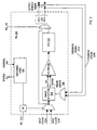
- PLL 100 is configured to generate an output signal 120 in response to an input signal 112.
- PLL 100 includes a phase detector 114, a loop filter 116, and a voltage-controlled oscillator (VCO) 118.
- Phase detector 114 is coupled to receive input clock signal 112 and to produce output clock signal 120.
- Phase detector 114 measures the phase difference between signals 112 and 120, and generates a phase error signal 115, which may be a voltage indicative of this phase difference. In some instances, phase detector 114 may also generate a signal even when there is no difference between signals 112 and 120.
- signal 115 becomes a time-varying signal into loop filter 116.
- the feedback signal 121 is an internal part of the PLL 100. It is noted, as is shown below, that the feedback signal 121 may be a signal external to the PLL 100.
- Loop filter 116 governs the response of PLL 100 to the error detected between signals 112 and 120.
- a well-designed loop filter 116 should be able to track changes in the incoming signal's phase but should not be overly responsive to signal noise.
- Loop filter 116 generates an error correction signal 117, which is the input to VCO 118.
- a zero voltage on signal 117 causes the output of VCO 118, output signal 120, to oscillate at a predefined frequency, ⁇ 0 , which is the "center" frequency of the oscillator.
- a positive voltage on error correction signal 117 causes output signal 120 to oscillate at a frequency which is greater than ⁇ 0 .
- a negative voltage on error correction signal 117 causes output signal 120 to oscillate at a frequency less than ⁇ 0 .
- either a positive voltage or a negative voltage on error correction signal 117 is generated.
- an error correction signal 117 is output.
- the error correction signal 117 is scaled such that although the error correction signal 117 is always of one sign, such as always positive, the error correction signal 117 corrects for oscillation either above or below the predefined frequency.
- the output frequency of VCO 118 is a linear function of its input voltage over some range of input and output. "Phase lock" is achieved by feeding the output of VCO 118 back to phase detector 114 so that continual error correction may be performed. It is noted that PLL 100 may not achieve phase lock if reference signal 112 is outside of some predetermined range.
- loop filter 116 is simply a conductor, that is, phase error signal 115 is equal to error correction signal 117.
- phase error signal 115 is equal to error correction signal 117.
- Such a filter 116 allows PLL 100 to generate an output signal 120 which matches reference signal 112 in frequency and phase only if reference signal 112 is equal to the center frequency of VCO 118. If reference signal 112 oscillates at a different frequency from the center frequency of VCO 118, output signal 120 may match reference signal 112 in frequency but not phase.
- This "wire filter” is an example of a first-order PLL, which means that the denominator of the loop filter transfer function has no exponent value greater than one.
- loop filter 116 includes an amplifier.
- Second-order PLLs such as shown in Fig. 2, are more commonly used than first-order PLLs 100.
- the second-order PLL 200 also incorporates a mechanism for switching input clock signals between a first clock source 222A and a second clock source 222B. It is noted that the first clock source 222A and the second clock source 222B are preferably synchronized in frequency and in phase.
- the selection of the input clock signal from the first clock source 222A or the second clock source 222B may be made by a SEL_CLK input or by the switching logic 230.
- Switching logic 230 receives CONTROL inputs and outputs STATUS information.
- the input clock signal is provided to a phase detector 214.
- the phase detector outputs a phase error signal 215 as a combination of UP and/or DOWN pulses.
- UP and DOWN pulses are typically digital signals indicative of the phase difference between the input clock signal and the feedback signal 221.
- the UP pulse is indicative of a phase difference between the feedback signal 221 and the input clock signal when an edge of the feedback signal 221occurs after a corresponding edge of the input clock signal.
- the DOWN pulse is indicative of a phase difference between the feedback signal 221 and the input clock signal when an edge of the feedback signal 221 occurs before a corresponding edge of the input clock signal.
- the second-order PLL has an integrating loop filter 216.
- a second order loop filter 216 performs an integration function, such as that typically found in a low-pass filter. This functionality allows the second-order PLL 200 to generate an output signal 220 which matches reference signal 212 in phase and frequency when reference signal 222 is not identical to the center frequency of VCO 218. This is possible since the second-order loop filter is configured to generate a non-zero error correction signal even when signals 222 and 220 match in phase. This non-zero error correction signal allows VCO 218 to oscillate at above or below its center frequency while remaining in phase with reference input clock signal 222.
- third-order (and possibly higher-order) PLLs exist and are commonly used in circuits such as those used in cellular and satellite communications.
- Third-order PLLs include third-order loop filters configured to perform double integration, which allows frequency and phase synchronization to occur even with a Doppler shift between the reference clock signal end output signal.
- multipliers and/or dividers are also used to generate an output signal, which is different, such as in frequency or phase, than the reference input signal.
- An important feature of the PLL 200 of Fig. 2 is the ability to switch between an input clock signal 222A from a first clock source and the input clock signal 222B from a second clock source.
- the switching logic 230 is configured to detect a failure of the input clock signal 222A from the first clock source and to cause the input clock signal 222B from the second clock source to be provided to phase detector 214 in the place of the input clock signal 222A.
- the switching logic 230 responds fairly quickly to the failure of the clock source, by the time the new clock source is switched in, the effects of the "bad" clock (or loss of clock) has propagated through the PLL 200 and has modified the feedback signal 221 such that the PLL 200 can no longer maintain the phase synchronization between the input clock signal and the feedback signal (i.e. the PLL 200 loses phase lock).
- What is needed is a PLL system and method of operation thereof that switches between the input clock signals from a first clock source and a second clock source without losing lock.
- a phase locked loop (PLL) and controller that provide fail-over redundant clocking.
- the PLL switches between input clock signals from different clock sources without losing lock by providing a supplemental correction signal to the loop filter in a PLL circuit.
- the phase detector includes a supplemental correction pulse generator configured to offset, at least partially, the effects of losing the input clock signal from a first clock source failure.
- the phase detector is coupled to receive an input clock signal from a first clock source and a feedback signal.
- the phase detector outputs a phase error signal indicative of a comparison between the input clock signal and the feedback signal.
- the loop filter is coupled to receive the phase error signal and to output an error correction signal.
- a voltage controlled oscillator is coupled to receive the error correction signal and to generate the output signal of the PLL.
- the feedback signal is indicative of the output signal of the PLL.
- Switching logic is coupled to monitor the input clock signal from the first clock source for a failure. In response to detecting the failure of the first clock source, the switching logic is configured to cause the input clock signal from a second clock source to be provided to the phase detector. Also in response to detecting the failure of the first clock source, the supplemental error correction signal is injected. This configuration may advantageously maintain lock in the PLL circuit while switching between clock sources for the input clock signal.
- the phase detector further includes a pulse width limiting circuit.
- the pulse width limiting circuit is configured to shorten each phase error output signal by a predetermined amount.
- the phase error signals are digital signals comprising an UP signal and a DOWN signal.
- the pulse widths of the UP and the DOWN signal are each shortened by the pulse width limiting circuit.
- failure of the clock source is defined as an absence of three or more clock edges of the input clock signal.
- the failure results in a maximum length DOWN pulse.
- the supplemental correction signal comprises a maximum length UP pulse.
- the shortened phase error output signal may advantageously result in slower PLL output drift upon the failure of the input clock signal.
- a method is likewise contemplated for operating a PLL circuit.
- the method comprises, in one embodiment, detecting a phase difference between an input clock signal from a first clock source and a feedback signal.
- the method further outputs a phase error signal indicative of the phase difference.
- the phase error signal is converted into an error correction signal.
- the method produces oscillations in response to the error correction signal, with the feedback signal indicative of the oscillations.
- the method further monitors the input clock signal from the first clock source for a failure. In response to the failure, the method provides the input clock signal from a second clock source in place of the input clock signal from the first clock source.
- the method further outputs a supplemental correction signal in response to the failure.
- the method may advantageously maintain lock in the PLL circuit while switching between clock sources for the input clock signal.
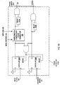
- PLL 300 Preferably implemented as a monolithic integrated circuit, PLL 300 includes a first multiplexer coupled to receive a first input clock signal 322A from a first clock source and a second input clock signal 322B from a second clock source.
- the multiplexer is controlled by a signal from an OR block coupled to receive a select clock input SEL_CLK and the output of switching logic 330.
- the select clock input sets the identity of the primary clock input Switching logic 330 receives CONTROL inputs 332 and outputs STATUS outputs 331.
- the output of the input multiplexer is the input clock signal provided to the phase detector 314 and to an output multiplexer.
- the phase detector 314 receives the input clock signal 322 from the input multiplexer and a feedback signal 321 from a feedback multiplexer.
- the phase detector is configured to produce a phase error signal 315 indicative of the difference between the input clock signal and the feedback signal 321.
- the phase error signal 315 comprises an UP pulse and a DOWN pulse, each preferably being digital signals.
- the UP pulse is indicative of a phase difference between the feedback signal 321 and the input clock signal 322 when an edge of the feedback signal 321occurs after a corresponding edge of the input clock signal 322.
- the DOWN pulse is indicative of a phase difference between the feedback signal 321 and the input clock signal 322 when an edge of the feedback signal 321 occurs before a corresponding edge of the input clock signal 322.
- a loop filter 316 is coupled to receive the phase error signal and to output an error correction signal to a voltage controller oscillator (VCO) 318.
- the loop filter comprises an active low-pass filter configured as an integrator.
- the VCO 318 is coupled to receive the an error correction signal from the loop filter 316 and to produce oscillations indicative of the error correction signal.
- the oscillating signal is presented as a second input to the output multiplexer.
- a PLL enable signal PLL_EN is provided to either select the output of the VCO or the input clock signal 322 to output.
- the output of the output multiplexer is divided in a divider circuit 319, either by 2 or 4 as shown, to produce one or more PLL output signals 320 A/B.
- the feedback signals 321A and 321B are shown coupled to the output signals of the PLL 320A/B.
- the input clock signals 322A and 322B are provided to the switching logic 330. Also provided are CONTROL signals 332, including an alarm reset ALARM_RESET 402 and a manual override MAN_OVERRIDE 404.
- the switching logic 330 outputs STATUS signals 331, including an indication of which input clock signal is selected CLK_SELECTED 408, and an indication if either input clock has failed INP0_BAD 406A and INP1_BAD 406B.
- the PLL 300 will use the second input clock 322B upon the failure of the first input clock 322A until the alarm reset signal 402 is received.
- the manual override operates to disable the switching logic 330.
- the switching logic 330 may also be configured to monitor the phase error signal 315 or other signals, as desired, in order to detect a failure of the input clock signal 322 or the feedback signal 321.
- additional CONTROL signals 332 and STATUS signals 331 are also contemplated.
- Figs. 5A and 5B embodiments of the phase detector 314 are illustrated.
- the phase comparison logic 520 provides a signal indicative of the phase difference between the input clock signal 322 and the feedback signal 321 to output logic 530.
- the output logic 530 further receives the manual override signal MAN_OVERRIDE 404 and the failure notification signal INP#_BAD 406.
- the output logic 530 includes a supplemental correction pulse generator 535 and a pulse width limiting circuit 537.
- the output logic 530 provides the phase error signal 315 to the loop filter 316. It is noted that in the embodiment illustrated in Fig. 5A, the phase error signal 315 comprises a digital UP signal and a digital DOWN signal.
- phase detector 314B one specific embodiment of phase detector 314B is shown. It is noted that a variety of circuits and components may be substituted for those shown, as suggested in Fig. 5A.
- the input clock signal 322 and the feedback signal 321 are provided to the clock inputs of a pair of flip-flops 524A and 524B, respectively, which has the data input lines held HIGH.
- the flip-flops 524A and 524B each output a logical "1". The output is maintained at logical "1" until both output lines are high.
- the output lines of the flip-flops 524A and 524B are combined by a logical AND, with the result provided to the RESET inputs of both flip-flops 524A and 524B.
- the flip-flops 524A and 524B reset when both flip-flops 524A and 524B output a logical "1".
- the outputs of the flip-flops 524A and 524B are provided to logical ANDs on the output of the phase detector 314B, both directly and through delay elements 512A and 512B, respectively.
- the supplemental correction pulse generator 535 coupled in series on the UP side of the phase detector 314B is configured to output a maximum UP pulse upon receiving notification of a failure of the input clock signal 322 from the present source. As shown, the supplemental correction pulse generator 535 also receives the manual override MAN_OVERRIDE signal 404 and the clock source failure notification signal(s) INP#_BAD 406. In one embodiment, the supplemental correction pulse generator 535 includes a resettable one-shot. Other circuits capable of providing a pulse are also contemplated.
- the output of the phase detector 314B includes the phase error signal 315 comprising in this embodiment, a digital UP pulse and a digital DOWN pulse.
- the UP pulse results from the clock edge of the input clock signal 322 being provided to the phase detector 314B ahead of the corresponding clock edge of the feedback signal 321.
- flip-flop 524A outputs a logical "1" before flip-flop 524B outputs a logical "1".
- the length of the UP pulse is limited by the pulse limitation of the delay 512A.
- the minimum and maximum pulse width of the UP pulse may be predetermined by the length of time of the delay provided by delay element 512A and by the reset time of the flip-flop 524A, relative to the clock period of the input clock signal 322.
- the DOWN pulse results from the clock edge of the input clock signal 322 being provided to the phase detector 314B after the corresponding clock edge of the feedback signal 321.
- flip-flop 524B outputs a logical "1" before flip-flop 524A outputs a logical "1".
- the length of the DOWN pulse is limited by the pulse limitation of the delay 512B.
- the minimum and maximum pulse width of the DOWN pulse may be predetermined by the length of time of the delay provided by delay element 512B and by the reset time of the flip-flop 524B, relative to the clock period of the input clock signal 322.
- phase detector 314B at least a minimum UP pulse and a minimum DOWN pulse are generated for each rising edge of the input clock signal 322.
- the supplemental correction pulse generator 535 may also be located in series with the DOWN pulse or in series with both the UP pulse and the DOWN pulse. For example, in an embodiment with the supplemental correction pulse generator 535 in series with the DOWN pulse, a runaway input clock signal 322 is determined to have failed. The supplemental correction pulse generator 535 is notified of the failure and generates a maximum pulse width DOWN pulse.
- Fig. 6A illustrates the PLL 300 speeding up to match the input clock signal
- Fig. 6B 6A illustrates the PLL 300 slowing down to match the input clock signal.
- the input clock signal 322, used as a timing reference, and feedback signal 321 are compared to detect a phase difference.
- the phase difference is output as a pair of digital pulses UP 315A and DOWN 315B that are indicative of the phase difference.
- the phase difference signals UP 315A and DOWN 315B are converted into an error correction signal used to produce oscillations.
- the feedback signal 321 is indicative of the oscillations.
- time period 620 the rising edge of the input clock signal 322 is detected ahead of the corresponding rising edge of the feedback signal 321.
- a relatively wide UP pulse 315A and a minimum DOWN pulse 315B are generated in response to the phase difference between the input clock signal 322 and the feedback signal 321.
- the relatively wide UP pulse 315A of time period 620 shortens the period of the feedback signal 321 such that the next rising edge of the feedback signal 321 is detected during time period 621 a shorter time after the corresponding rising edge of the input clock signal 322.
- a narrower UP pulse 315A (relative to the UP pulse 315A of time period 620) and a minimum DOWN pulse 315B are generated in response to the phase difference between the input clock signal 322 and the feedback signal 321.
- the narrower UP pulse 315A is wider than the minimum DOWN pulse 315B.
- the narrower UP pulse 315A of time period 621 shortens the period of the feedback signal 321 such that the next rising edge of the feedback signal 321 is detected during time period 622 only a short period of time after the corresponding rising edge of the input clock signal 322.
- an even narrower UP pulse 315A (relative to the UP pulse 315A of time period 621) and a minimum DOWN pulse 315B are generated in response to the phase difference between the input clock signal 322 and the feedback signal 321.
- the even narrower UP pulse 315A is only slightly wider than the minimum DOWN pulse 315B.
- the effect of the even narrower UP pulse 315A of time period 622 just shortens the period of the feedback signal 321 such that the next rising edge of the feedback signal 321 is detected during time period 623 substantially concurrently with the corresponding rising edge of the input clock signal 322.
- a minimum UP pulse 315A and a minimum DOWN pulse 315B are generated in response to the phase difference between the input clock signal 322 and the feedback signal 321.
- the minimum UP pulse 315A is substantially the same width as the minimum DOWN pulse 315B in a preferred embodiment. Other pulse width minimums are, however, contemplated.
- the input clock signal 322 is again used as a timing reference and is compared to feedback signal 321 to detect a phase difference.
- the phase difference is output as a pair of digital pulses UP 315A and DOWN 315B that are indicative of the phase difference.
- the phase difference signals UP 315A and DOWN 315B are convened into an error correction signal used to produce oscillations.
- the feedback signal 321 is indicative of the oscillations.
- time period 670 the rising edge of the input clock signal 322 is detected a substantial period of time after the corresponding rising edge of the feedback signal 321.
- a relatively wide DOWN pulse 315B and a minimum UP pulse 315A are generated in response to the phase difference between the input clock signal 322 and the feedback signal 321.
- the relatively wide DOWN pulse 315B of time period 670 lengthens the period of the feedback signal 321 such that the next rising edge of the feedback signal 321 is detected during time period 671 only a short time before the corresponding rising edge of the input clock signal 322.
- a relatively narrow DOWN pulse 315B (relative to the DOWN pulse 315B of time period 670) and a minimum UP pulse 315A are generated in response to the phase difference between the input clock signal 322 and the feedback signal 321.
- the relatively narrow DOWN pulse 315B is wider than the minimum UP pulse 315A.
- the relatively narrow DOWN pulse 315B of time period 671 shortens the period of the feedback signal 321 such that the next rising edge of the feedback signal 321 is detected during time period 672 slightly after the corresponding rising edge of the input clock signal 322.
- a relatively narrow UP pulse 315A and a minimum DOWN pulse 315B are generated in response to the phase difference between the input clock signal 322 and the feedback signal 321.
- the relatively narrow UP pulse 315A is only slightly wider than the minimum DOWN pulse 315B.
- the effect of the relatively narrow UP pulse 315A of time period 672 just shortens the period of the feedback signal 321 such that the next rising edge of the feedback signal 321 is detected during time period 672 substantially concurrently with the corresponding rising edge of the input clock signal 322.
- a minimum UP pulse 315A and a minimum DOWN pulse 315B are generated in response to the phase difference between the input clock signal 322 and the feedback signal 321.
- the minimum UP pulse 315A is substantially the same width as the minimum DOWN pulse 315B in a preferred embodiment Other pulse width minimums are, however, contemplated.
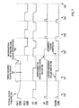
- a timing diagram of several advanced operations of the PLL of Fig. 3, including switchover to a backup clock source, limited width phase error signal pulses, and a supplemental error correction pulse are illustrated.
- the first reference clock signal REF1 is shown as input clock signal 322A from a first clock source.
- the second reference clock signal REF2 is shown as input clock signal 322B from a second clock source.
- the feedback signal 321 and the input clock signal 322 are compared, as in Figs. 6A and 6B, to produce a phase error signal.
- An UP pulse 315A and a DOWN pulse 315B are shown as comprising the phase error signal.
- time period 720 the first input clock signal 322A and the feedback signal 321 are in phase.
- a minimum width UP pulse 315A and a minimum width DOWN pulse 315B are shown. Note that the first input clock signal 322A fails 780 during time period 780.
- the first input clock signal 322A is monitored for a failure. However, as shown, the failure may not be recognized until time period 721, when three clock edges are missed 781.
- the feedback signal 321 shows a longer period in response to the lack of an UP pulse 315A and the extremely width DOWN pulse 315B.
- the pulse width of the DOWN pulse 315B is limited to a predetermined maximum width 790. The unlimited pulse width is shown as 791.
- the input clock source failure is recognized and the input clock is switched over to a second input clock source 322B in response.
- the supplemental error correction pulse 792 is injected as a maximum length UP pulse.
- the backup input clock signal 322B is now the reference clock signal.
- the supplemental error correction pulse 792 results in the feedback signal 321 having a shorter period than in clock period 721, closer to the correct phase alignment with the reference clock signal that would occur without the supplemental error correction pulse 792. Note that the missing UP pulse 315A from clock period 721 may occur in clock period 722. It is not seen in clock period 722 due to the supplemental error correction pulse 792.
- the supplemental error correction pulse 792 is in addition to the UP pulse 315A. In another embodiment, the supplemental error correction pulse 792 replaces the UP pulse 315A.
- the PLL circuit aligns the reference clock signal 322B and the feedback signal 321 in a manner similar to that shown in Figs. 6A and 6B. Note that in clock period 725, the input clock signal 322B and the feedback signal 321 are in phase. It is noted that a failure of a clock source may be defined as the loss of as few as one clock edge, either rising or falling.
Applications Claiming Priority (2)
| Application Number | Priority Date | Filing Date | Title |
|---|---|---|---|
| US09/236,865 US6359945B1 (en) | 1999-01-25 | 1999-01-25 | Phase locked loop and method that provide fail-over redundant clocking |
| US236865 | 1999-01-25 |
Publications (3)
| Publication Number | Publication Date |
|---|---|
| EP1022857A2 true EP1022857A2 (fr) | 2000-07-26 |
| EP1022857A3 EP1022857A3 (fr) | 2003-08-27 |
| EP1022857B1 EP1022857B1 (fr) | 2006-03-15 |
Family
ID=22891315
Family Applications (1)
| Application Number | Title | Priority Date | Filing Date |
|---|---|---|---|
| EP00300462A Expired - Lifetime EP1022857B1 (fr) | 1999-01-25 | 2000-01-21 | Boucle à verrouillage de phase et procédé produisant un cadencement redondant de secours |
Country Status (5)
| Country | Link |
|---|---|
| US (2) | US6359945B1 (fr) |
| EP (1) | EP1022857B1 (fr) |
| JP (1) | JP2000224036A (fr) |
| AT (1) | ATE320676T1 (fr) |
| DE (1) | DE60026656D1 (fr) |
Cited By (1)
| Publication number | Priority date | Publication date | Assignee | Title |
|---|---|---|---|---|
| WO2014000434A1 (fr) * | 2012-06-29 | 2014-01-03 | 华为技术有限公司 | Procédé et système pour exécuter une synchronisation temporelle |
Families Citing this family (38)
| Publication number | Priority date | Publication date | Assignee | Title |
|---|---|---|---|---|
| US6590949B1 (en) * | 1999-02-11 | 2003-07-08 | Motorola, Inc. | Circuit and method for compensating a phase detector |
| US6470060B1 (en) * | 1999-03-01 | 2002-10-22 | Micron Technology, Inc. | Method and apparatus for generating a phase dependent control signal |
| EP1269706B1 (fr) * | 2000-04-04 | 2006-11-02 | Broadcom Corporation | Procede de compensation d'erreurs de phase de signaux multiporteurs |
| US7042970B1 (en) * | 2001-06-15 | 2006-05-09 | Analog Devices, Inc. | Phase frequency detector with adjustable offset |
| US20030115503A1 (en) * | 2001-12-14 | 2003-06-19 | Koninklijke Philips Electronics N.V. | System for enhancing fault tolerance and security of a computing system |
| EP1476800B1 (fr) * | 2002-02-14 | 2010-11-17 | TELEFONAKTIEBOLAGET LM ERICSSON (publ) | Signaux d'horloge continus |
| US6806751B2 (en) | 2002-09-12 | 2004-10-19 | Foundry Networks, Inc. | Loop filter for a phase-locked loop and method for switching |
| US7089442B2 (en) * | 2003-02-07 | 2006-08-08 | Rambus Inc. | Fault-tolerant clock generator |
| US6970045B1 (en) | 2003-06-25 | 2005-11-29 | Nel Frequency Controls, Inc. | Redundant clock module |
| US7295644B1 (en) * | 2003-07-14 | 2007-11-13 | Marvell International Ltd. | Apparatus for clock data recovery |
| TWI226754B (en) * | 2003-09-12 | 2005-01-11 | Mediatek Inc | Device and method for detecting phase difference and PLL using the same |
| US7130722B2 (en) * | 2005-02-22 | 2006-10-31 | Distribution Control Systems, Inc. | Smart disconnect switch interbase |
| US20060193417A1 (en) * | 2005-02-25 | 2006-08-31 | Tellabs Operations, Inc. | Systems and methods for switching between redundant clock signals |
| US7508274B2 (en) * | 2005-05-25 | 2009-03-24 | Radioframe Networks, Inc. | PLL with phase clipping and resynchronization |
| US7724100B2 (en) * | 2007-01-31 | 2010-05-25 | Infineon Technologies Austria Ag | Oscillator structure |
| US20080218276A1 (en) * | 2007-03-05 | 2008-09-11 | Exar Corporation | Means to control pll phase slew rate |
| US20080218278A1 (en) * | 2007-03-05 | 2008-09-11 | Exar Corporation | Means to control pll phase slew rate |
| KR100822307B1 (ko) * | 2007-09-20 | 2008-04-16 | 주식회사 아나패스 | 데이터 구동 회로 및 지연 고정 루프 |
| US7551039B2 (en) * | 2007-10-19 | 2009-06-23 | Hewlett-Packard Development Company, L.P. | Phase adjustment in phase-locked loops using multiple oscillator signals |
| US7864912B1 (en) | 2007-10-19 | 2011-01-04 | Marvell International Ltd. | Circuits, architectures, a system and methods for improved clock data recovery |
| US7554466B1 (en) * | 2007-12-05 | 2009-06-30 | Broadcom Corporation | Multi-speed burst mode serializer/de-serializer |
| US8526559B2 (en) * | 2008-05-30 | 2013-09-03 | Mediatek Inc. | Communication systems and clock generation circuits thereof with reference source switching |
| US8201069B2 (en) * | 2008-07-01 | 2012-06-12 | International Business Machines Corporation | Cyclical redundancy code for use in a high-speed serial link |
| US8139430B2 (en) * | 2008-07-01 | 2012-03-20 | International Business Machines Corporation | Power-on initialization and test for a cascade interconnect memory system |
| US7895374B2 (en) * | 2008-07-01 | 2011-02-22 | International Business Machines Corporation | Dynamic segment sparing and repair in a memory system |
| US8082474B2 (en) * | 2008-07-01 | 2011-12-20 | International Business Machines Corporation | Bit shadowing in a memory system |
| US8234540B2 (en) * | 2008-07-01 | 2012-07-31 | International Business Machines Corporation | Error correcting code protected quasi-static bit communication on a high-speed bus |
| US8082475B2 (en) * | 2008-07-01 | 2011-12-20 | International Business Machines Corporation | Enhanced microprocessor interconnect with bit shadowing |
| US20100005335A1 (en) * | 2008-07-01 | 2010-01-07 | International Business Machines Corporation | Microprocessor interface with dynamic segment sparing and repair |
| US8245105B2 (en) * | 2008-07-01 | 2012-08-14 | International Business Machines Corporation | Cascade interconnect memory system with enhanced reliability |
| US7979759B2 (en) * | 2009-01-08 | 2011-07-12 | International Business Machines Corporation | Test and bring-up of an enhanced cascade interconnect memory system |
| US20100180154A1 (en) * | 2009-01-13 | 2010-07-15 | International Business Machines Corporation | Built In Self-Test of Memory Stressor |
| US20110248755A1 (en) * | 2010-04-08 | 2011-10-13 | Hasenplaugh William C | Cross-feedback phase-locked loop for distributed clocking systems |
| JP5598161B2 (ja) * | 2010-08-26 | 2014-10-01 | ヤマハ株式会社 | クロック発生回路 |
| KR101238440B1 (ko) | 2011-12-30 | 2013-02-28 | 주식회사 더즈텍 | 위상 손실 검출기 |
| WO2018189288A1 (fr) * | 2017-04-12 | 2018-10-18 | Telefonaktiebolaget Lm Ericsson (Publ) | Suppression d'impulsions courtes d'un détecteur de phase/fréquence |
| CN107872414B (zh) * | 2017-12-01 | 2020-07-14 | 珠海亿智电子科技有限公司 | 一种用于bpsk信号解调的新型鉴相器 |
| CN114679173B (zh) * | 2021-10-06 | 2022-08-30 | 绍兴圆方半导体有限公司 | 锁相环和时钟同步系统 |
Citations (5)
| Publication number | Priority date | Publication date | Assignee | Title |
|---|---|---|---|---|
| JPS63287210A (ja) * | 1987-05-20 | 1988-11-24 | Sumitomo Electric Ind Ltd | ディジタル位相同期ル−プ |
| US4914404A (en) * | 1988-08-02 | 1990-04-03 | Siemens Aktiengesellschaft | Method for synchronization of a signal frequency to interference-prone reference signal frequencies |
| EP0515074A2 (fr) * | 1991-05-21 | 1992-11-25 | National Semiconductor Corporation | Oscillateur contrôlé en fréquence pour une boucle à verrouillage de phase haute fréquence |
| JPH11331067A (ja) * | 1998-05-20 | 1999-11-30 | Oki Electric Ind Co Ltd | ディジタル・フェーズロックド・ループ発振器 |
| US20020006178A1 (en) * | 2000-06-30 | 2002-01-17 | Konica Corporation | Digital PLL pulse generating apparatus |
Family Cites Families (9)
| Publication number | Priority date | Publication date | Assignee | Title |
|---|---|---|---|---|
| US4025874A (en) | 1976-04-30 | 1977-05-24 | Rockwell International Corporation | Master/slave clock arrangement for providing reliable clock signal |
| US4282493A (en) | 1979-07-02 | 1981-08-04 | Motorola, Inc. | Redundant clock signal generating circuitry |
| US4972442A (en) * | 1989-04-27 | 1990-11-20 | Northern Telecom Limited | Phase-locked loop clock |
| US5699387A (en) * | 1993-06-23 | 1997-12-16 | Ati Technologies Inc. | Phase offset cancellation technique for reducing low frequency jitters |
| US5638410A (en) * | 1993-10-14 | 1997-06-10 | Alcatel Network Systems, Inc. | Method and system for aligning the phase of high speed clocks in telecommunications systems |
| GB2293062B (en) | 1994-09-09 | 1996-12-04 | Toshiba Kk | Master-slave multiplex communication system and PLL circuit applied to the system |
| US5592113A (en) * | 1995-03-28 | 1997-01-07 | National Semiconductor Corp. | Gradual frequency changing circuit |
| JPH10124167A (ja) | 1996-10-17 | 1998-05-15 | Miyagi Oki Denki Kk | システムクロック切り換え装置 |
| US6084479A (en) * | 1998-05-28 | 2000-07-04 | Cypress Semiconductor Corp. | Circuit, architecture and method(s) of controlling a periodic signal generating circuit or device |
-
1999
- 1999-01-25 US US09/236,865 patent/US6359945B1/en not_active Expired - Lifetime
-
2000
- 2000-01-21 EP EP00300462A patent/EP1022857B1/fr not_active Expired - Lifetime
- 2000-01-21 AT AT00300462T patent/ATE320676T1/de not_active IP Right Cessation
- 2000-01-21 DE DE60026656T patent/DE60026656D1/de not_active Expired - Lifetime
- 2000-01-25 JP JP2000015468A patent/JP2000224036A/ja not_active Withdrawn
-
2001
- 2001-11-26 US US09/994,344 patent/US6731709B2/en not_active Expired - Lifetime
Patent Citations (5)
| Publication number | Priority date | Publication date | Assignee | Title |
|---|---|---|---|---|
| JPS63287210A (ja) * | 1987-05-20 | 1988-11-24 | Sumitomo Electric Ind Ltd | ディジタル位相同期ル−プ |
| US4914404A (en) * | 1988-08-02 | 1990-04-03 | Siemens Aktiengesellschaft | Method for synchronization of a signal frequency to interference-prone reference signal frequencies |
| EP0515074A2 (fr) * | 1991-05-21 | 1992-11-25 | National Semiconductor Corporation | Oscillateur contrôlé en fréquence pour une boucle à verrouillage de phase haute fréquence |
| JPH11331067A (ja) * | 1998-05-20 | 1999-11-30 | Oki Electric Ind Co Ltd | ディジタル・フェーズロックド・ループ発振器 |
| US20020006178A1 (en) * | 2000-06-30 | 2002-01-17 | Konica Corporation | Digital PLL pulse generating apparatus |
Non-Patent Citations (2)
| Title |
|---|
| PATENT ABSTRACTS OF JAPAN vol. 013, no. 117 (E-731), 22 March 1989 (1989-03-22) -& JP 63 287210 A (SUMITOMO ELECTRIC IND LTD), 24 November 1988 (1988-11-24) * |
| PATENT ABSTRACTS OF JAPAN vol. 2000, no. 02, 29 February 2000 (2000-02-29) -& JP 11 331067 A (OKI ELECTRIC IND CO LTD), 30 November 1999 (1999-11-30) * |
Cited By (1)
| Publication number | Priority date | Publication date | Assignee | Title |
|---|---|---|---|---|
| WO2014000434A1 (fr) * | 2012-06-29 | 2014-01-03 | 华为技术有限公司 | Procédé et système pour exécuter une synchronisation temporelle |
Also Published As
| Publication number | Publication date |
|---|---|
| ATE320676T1 (de) | 2006-04-15 |
| US6731709B2 (en) | 2004-05-04 |
| DE60026656D1 (de) | 2006-05-11 |
| EP1022857B1 (fr) | 2006-03-15 |
| US20020075982A1 (en) | 2002-06-20 |
| US6359945B1 (en) | 2002-03-19 |
| JP2000224036A (ja) | 2000-08-11 |
| EP1022857A3 (fr) | 2003-08-27 |
Similar Documents
| Publication | Publication Date | Title |
|---|---|---|
| EP1022857B1 (fr) | Boucle à verrouillage de phase et procédé produisant un cadencement redondant de secours | |
| US6295327B1 (en) | Method and apparatus for fast clock recovery phase-locked loop with training capability | |
| JP3255418B2 (ja) | ディジタル制御の水晶発振器 | |
| US5978425A (en) | Hybrid phase-locked loop employing analog and digital loop filters | |
| US20100085086A1 (en) | Digital Frequency Detector | |
| JPH07193497A (ja) | ホールドオーバモードを持つ位相ロックループ回路のための方法及び装置 | |
| US6222420B1 (en) | Minimizing recovery time | |
| US20070273410A1 (en) | Clock switching circuit | |
| JP2007135208A (ja) | 電子回路及び電子回路を動作するための方法 | |
| US6538518B1 (en) | Multi-loop phase lock loop for controlling jitter in a high frequency redundant system | |
| CN113839668A (zh) | 双模锁相环电路、振荡电路及振荡电路的控制方法 | |
| US6526374B1 (en) | Fractional PLL employing a phase-selection feedback counter | |
| EP0479237B1 (fr) | Système à circuit oscillant verrouillé en phase comportant un moyen contre l'interruption de l'horloge d'entrée | |
| CN112994687A (zh) | 一种参考时钟信号注入锁相环电路及消除失调方法 | |
| US6218907B1 (en) | Frequency comparator and PLL circuit using the same | |
| JPH11317729A (ja) | クロックデータリカバリ回路 | |
| EP3457572B1 (fr) | Circuit générateur d'horloge et procédé de génération de signal d'horloge | |
| WO1999013582A1 (fr) | Boucle a phase asservie numerique peu sensible aux perturbations employant un detecteur de phase-frequence | |
| KR102205037B1 (ko) | 글리치를 제거하기 위한 멀티 모듈러스 분주기 및 이를 포함하는 전자 장치 | |
| JPH07273643A (ja) | 位相同期回路 | |
| JPH05315950A (ja) | Pll回路 | |
| KR200242921Y1 (ko) | 시스템클럭이중화장치 | |
| JP2795008B2 (ja) | 位相同期発振回路の耐入力クロック断回路方式 | |
| JPH04290307A (ja) | 位相同期発振回路 | |
| JPH1127247A (ja) | 系切替方式 |
Legal Events
| Date | Code | Title | Description |
|---|---|---|---|
| PUAI | Public reference made under article 153(3) epc to a published international application that has entered the european phase |
Free format text: ORIGINAL CODE: 0009012 |
|
| AK | Designated contracting states |
Kind code of ref document: A2 Designated state(s): AT BE CH CY DE DK ES FI FR GB GR IE IT LI LU MC NL PT SE |
|
| AX | Request for extension of the european patent |
Free format text: AL;LT;LV;MK;RO;SI |
|
| RAP1 | Party data changed (applicant data changed or rights of an application transferred) |
Owner name: SUN MICROSYSTEMS, INC. |
|
| PUAL | Search report despatched |
Free format text: ORIGINAL CODE: 0009013 |
|
| AK | Designated contracting states |
Designated state(s): AT BE CH CY DE DK ES FI FR GB GR IE IT LI LU MC NL PT SE |
|
| AX | Request for extension of the european patent |
Extension state: AL LT LV MK RO SI |
|
| RIC1 | Information provided on ipc code assigned before grant |
Ipc: 7H 03L 7/089 B Ipc: 7H 03L 7/14 A |
|
| 17P | Request for examination filed |
Effective date: 20040211 |
|
| AKX | Designation fees paid |
Designated state(s): AT BE CH CY DE DK ES FI FR GB GR IE IT LI LU MC NL PT SE |
|
| 17Q | First examination report despatched |
Effective date: 20050415 |
|
| GRAP | Despatch of communication of intention to grant a patent |
Free format text: ORIGINAL CODE: EPIDOSNIGR1 |
|
| GRAS | Grant fee paid |
Free format text: ORIGINAL CODE: EPIDOSNIGR3 |
|
| GRAA | (expected) grant |
Free format text: ORIGINAL CODE: 0009210 |
|
| AK | Designated contracting states |
Kind code of ref document: B1 Designated state(s): AT BE CH CY DE DK ES FI FR GB GR IE IT LI LU MC NL PT SE |
|
| PG25 | Lapsed in a contracting state [announced via postgrant information from national office to epo] |
Ref country code: IT Free format text: LAPSE BECAUSE OF FAILURE TO SUBMIT A TRANSLATION OF THE DESCRIPTION OR TO PAY THE FEE WITHIN THE PRESCRIBED TIME-LIMIT;WARNING: LAPSES OF ITALIAN PATENTS WITH EFFECTIVE DATE BEFORE 2007 MAY HAVE OCCURRED AT ANY TIME BEFORE 2007. THE CORRECT EFFECTIVE DATE MAY BE DIFFERENT FROM THE ONE RECORDED. Effective date: 20060315 Ref country code: NL Free format text: LAPSE BECAUSE OF FAILURE TO SUBMIT A TRANSLATION OF THE DESCRIPTION OR TO PAY THE FEE WITHIN THE PRESCRIBED TIME-LIMIT Effective date: 20060315 Ref country code: FI Free format text: LAPSE BECAUSE OF FAILURE TO SUBMIT A TRANSLATION OF THE DESCRIPTION OR TO PAY THE FEE WITHIN THE PRESCRIBED TIME-LIMIT Effective date: 20060315 Ref country code: AT Free format text: LAPSE BECAUSE OF FAILURE TO SUBMIT A TRANSLATION OF THE DESCRIPTION OR TO PAY THE FEE WITHIN THE PRESCRIBED TIME-LIMIT Effective date: 20060315 Ref country code: LI Free format text: LAPSE BECAUSE OF FAILURE TO SUBMIT A TRANSLATION OF THE DESCRIPTION OR TO PAY THE FEE WITHIN THE PRESCRIBED TIME-LIMIT Effective date: 20060315 Ref country code: CH Free format text: LAPSE BECAUSE OF FAILURE TO SUBMIT A TRANSLATION OF THE DESCRIPTION OR TO PAY THE FEE WITHIN THE PRESCRIBED TIME-LIMIT Effective date: 20060315 Ref country code: BE Free format text: LAPSE BECAUSE OF FAILURE TO SUBMIT A TRANSLATION OF THE DESCRIPTION OR TO PAY THE FEE WITHIN THE PRESCRIBED TIME-LIMIT Effective date: 20060315 |
|
| REG | Reference to a national code |
Ref country code: CH Ref legal event code: EP Ref country code: GB Ref legal event code: FG4D |
|
| REG | Reference to a national code |
Ref country code: IE Ref legal event code: FG4D |
|
| REF | Corresponds to: |
Ref document number: 60026656 Country of ref document: DE Date of ref document: 20060511 Kind code of ref document: P |
|
| PG25 | Lapsed in a contracting state [announced via postgrant information from national office to epo] |
Ref country code: DK Free format text: LAPSE BECAUSE OF FAILURE TO SUBMIT A TRANSLATION OF THE DESCRIPTION OR TO PAY THE FEE WITHIN THE PRESCRIBED TIME-LIMIT Effective date: 20060615 Ref country code: SE Free format text: LAPSE BECAUSE OF FAILURE TO SUBMIT A TRANSLATION OF THE DESCRIPTION OR TO PAY THE FEE WITHIN THE PRESCRIBED TIME-LIMIT Effective date: 20060615 |
|
| PG25 | Lapsed in a contracting state [announced via postgrant information from national office to epo] |
Ref country code: DE Free format text: LAPSE BECAUSE OF FAILURE TO SUBMIT A TRANSLATION OF THE DESCRIPTION OR TO PAY THE FEE WITHIN THE PRESCRIBED TIME-LIMIT Effective date: 20060617 |
|
| PG25 | Lapsed in a contracting state [announced via postgrant information from national office to epo] |
Ref country code: ES Free format text: LAPSE BECAUSE OF FAILURE TO SUBMIT A TRANSLATION OF THE DESCRIPTION OR TO PAY THE FEE WITHIN THE PRESCRIBED TIME-LIMIT Effective date: 20060626 |
|
| PG25 | Lapsed in a contracting state [announced via postgrant information from national office to epo] |
Ref country code: PT Free format text: LAPSE BECAUSE OF FAILURE TO SUBMIT A TRANSLATION OF THE DESCRIPTION OR TO PAY THE FEE WITHIN THE PRESCRIBED TIME-LIMIT Effective date: 20060816 |
|
| NLV1 | Nl: lapsed or annulled due to failure to fulfill the requirements of art. 29p and 29m of the patents act | ||
| REG | Reference to a national code |
Ref country code: CH Ref legal event code: PL |
|
| PLBE | No opposition filed within time limit |
Free format text: ORIGINAL CODE: 0009261 |
|
| STAA | Information on the status of an ep patent application or granted ep patent |
Free format text: STATUS: NO OPPOSITION FILED WITHIN TIME LIMIT |
|
| PG25 | Lapsed in a contracting state [announced via postgrant information from national office to epo] |
Ref country code: IE Free format text: LAPSE BECAUSE OF NON-PAYMENT OF DUE FEES Effective date: 20070122 |
|
| PG25 | Lapsed in a contracting state [announced via postgrant information from national office to epo] |
Ref country code: MC Free format text: LAPSE BECAUSE OF NON-PAYMENT OF DUE FEES Effective date: 20070131 |
|
| 26N | No opposition filed |
Effective date: 20061218 |
|
| EN | Fr: translation not filed | ||
| PG25 | Lapsed in a contracting state [announced via postgrant information from national office to epo] |
Ref country code: FR Free format text: LAPSE BECAUSE OF FAILURE TO SUBMIT A TRANSLATION OF THE DESCRIPTION OR TO PAY THE FEE WITHIN THE PRESCRIBED TIME-LIMIT Effective date: 20070309 Ref country code: GR Free format text: LAPSE BECAUSE OF FAILURE TO SUBMIT A TRANSLATION OF THE DESCRIPTION OR TO PAY THE FEE WITHIN THE PRESCRIBED TIME-LIMIT Effective date: 20060616 |
|
| PG25 | Lapsed in a contracting state [announced via postgrant information from national office to epo] |
Ref country code: FR Free format text: LAPSE BECAUSE OF FAILURE TO SUBMIT A TRANSLATION OF THE DESCRIPTION OR TO PAY THE FEE WITHIN THE PRESCRIBED TIME-LIMIT Effective date: 20060315 |
|
| PG25 | Lapsed in a contracting state [announced via postgrant information from national office to epo] |
Ref country code: LU Free format text: LAPSE BECAUSE OF NON-PAYMENT OF DUE FEES Effective date: 20070121 Ref country code: CY Free format text: LAPSE BECAUSE OF FAILURE TO SUBMIT A TRANSLATION OF THE DESCRIPTION OR TO PAY THE FEE WITHIN THE PRESCRIBED TIME-LIMIT Effective date: 20060315 |
|
| PGFP | Annual fee paid to national office [announced via postgrant information from national office to epo] |
Ref country code: GB Payment date: 20190116 Year of fee payment: 20 |
|
| REG | Reference to a national code |
Ref country code: GB Ref legal event code: PE20 Expiry date: 20200120 |
|
| PG25 | Lapsed in a contracting state [announced via postgrant information from national office to epo] |
Ref country code: GB Free format text: LAPSE BECAUSE OF EXPIRATION OF PROTECTION Effective date: 20200120 |