EP1020554B2 - Dispositif de conception d'articles à mailles produits dans des machines à tricoter - Google Patents
Dispositif de conception d'articles à mailles produits dans des machines à tricoter Download PDFInfo
- Publication number
- EP1020554B2 EP1020554B2 EP00100529A EP00100529A EP1020554B2 EP 1020554 B2 EP1020554 B2 EP 1020554B2 EP 00100529 A EP00100529 A EP 00100529A EP 00100529 A EP00100529 A EP 00100529A EP 1020554 B2 EP1020554 B2 EP 1020554B2
- Authority
- EP
- European Patent Office
- Prior art keywords
- display
- knitting
- knitted
- modules
- yarn
- Prior art date
- Legal status (The legal status is an assumption and is not a legal conclusion. Google has not performed a legal analysis and makes no representation as to the accuracy of the status listed.)
- Expired - Lifetime
Links
- 238000009940 knitting Methods 0.000 title claims abstract description 127
- 238000013461 design Methods 0.000 claims abstract description 53
- 238000006243 chemical reaction Methods 0.000 claims abstract description 6
- 230000002452 interceptive effect Effects 0.000 claims abstract description 6
- 238000000034 method Methods 0.000 claims description 13
- 238000004519 manufacturing process Methods 0.000 claims description 5
- 238000003780 insertion Methods 0.000 claims description 2
- 230000037431 insertion Effects 0.000 claims description 2
- 238000009943 combination knitting Methods 0.000 claims 1
- 239000004744 fabric Substances 0.000 abstract description 22
- 230000008859 change Effects 0.000 abstract description 7
- 238000000059 patterning Methods 0.000 abstract description 5
- 238000012546 transfer Methods 0.000 abstract description 5
- 238000012937 correction Methods 0.000 abstract description 2
- 238000005266 casting Methods 0.000 abstract 1
- 230000008569 process Effects 0.000 description 7
- 229920002334 Spandex Polymers 0.000 description 4
- 239000004759 spandex Substances 0.000 description 4
- 239000003086 colorant Substances 0.000 description 3
- 238000005070 sampling Methods 0.000 description 3
- 238000010586 diagram Methods 0.000 description 2
- 230000000694 effects Effects 0.000 description 2
- 230000010354 integration Effects 0.000 description 2
- 238000012986 modification Methods 0.000 description 2
- 230000004048 modification Effects 0.000 description 2
- 230000000007 visual effect Effects 0.000 description 2
- 206010003830 Automatism Diseases 0.000 description 1
- 230000015572 biosynthetic process Effects 0.000 description 1
- 239000002131 composite material Substances 0.000 description 1
- 238000001514 detection method Methods 0.000 description 1
- 238000009963 fulling Methods 0.000 description 1
- 238000010348 incorporation Methods 0.000 description 1
- 238000013507 mapping Methods 0.000 description 1
- 230000002093 peripheral effect Effects 0.000 description 1
- 238000012545 processing Methods 0.000 description 1
- 230000007704 transition Effects 0.000 description 1
- 238000013519 translation Methods 0.000 description 1
- 230000016776 visual perception Effects 0.000 description 1
Images


Classifications
-
- D—TEXTILES; PAPER
- D04—BRAIDING; LACE-MAKING; KNITTING; TRIMMINGS; NON-WOVEN FABRICS
- D04B—KNITTING
- D04B37/00—Auxiliary apparatus or devices for use with knitting machines
- D04B37/02—Auxiliary apparatus or devices for use with knitting machines with weft knitting machines
-
- D—TEXTILES; PAPER
- D04—BRAIDING; LACE-MAKING; KNITTING; TRIMMINGS; NON-WOVEN FABRICS
- D04B—KNITTING
- D04B7/00—Flat-bed knitting machines with independently-movable needles
- D04B7/24—Flat-bed knitting machines with independently-movable needles for producing patterned fabrics
- D04B7/26—Flat-bed knitting machines with independently-movable needles for producing patterned fabrics with colour patterns
-
- D—TEXTILES; PAPER
- D04—BRAIDING; LACE-MAKING; KNITTING; TRIMMINGS; NON-WOVEN FABRICS
- D04B—KNITTING
- D04B7/00—Flat-bed knitting machines with independently-movable needles
- D04B7/24—Flat-bed knitting machines with independently-movable needles for producing patterned fabrics
- D04B7/28—Flat-bed knitting machines with independently-movable needles for producing patterned fabrics with stitch patterns
Definitions
- the invention relates to a device for designing knitted products produced on a knitting or knitting machine with at least one storage device for receiving the necessary for the production of the knitted product on the knitting or knitting machine data, at least one display device for displaying design images of the knitted product and at least one input device to change the design images.
- Such patterning devices are for example from the EP 0 640 707 A1 , of the DE 44 31 898 A1 as well as the WO 94/11794 known. With these patterning systems, it is possible to fully exploit the knitting possibilities of electronically controlled, fully automatic knitting or knitting machines. It can be used to design and produce knitted fabrics with intricate weaves, highly complex color patterns and elaborate contours.
- the parameters of the knitted product to be produced are input in different input groups, which can or must be edited separately. These input groups mainly contain form information, color information, structure information, jacquard information and mesh size information. In addition, yarn properties and machine parameters must be entered. From these data, computer-controlled processing sequences form data with which a knitting or knitting machine can produce the desired knitted product.
- the knitted product is usually printed on the display device of the patterning machine in the form of a threadline (eg in the case of the yarn guide) WO 94/11794 ), which illustrates the knitting process - knitting series for knitting series - by symbols.
- the knitted product is also input and then converted by a conversion program into the control data for the knitting machine.
- the known from the above documents sampling systems have conversion programs that can convert the yarn path representation in a mesh display and display. However, a direct conversion of the mesh image representation in a yarn guide is not possible.
- the present invention has for its object to enable the generation of control data for the production of a knitted product for a knitting or knitting machine users without knowledge of the thread running line symbolism.
- the design device it is now possible to use both the yarn path representation and the mesh image representation for input and correction of the elements of a mesh product, wherein simultaneously the data of the other representations are mitver St.
- the device is thus suitable as a design tool for both pure fashion designers and for more technically oriented users.
- the mesh image representations and the associated yarn guide representations can be displayed simultaneously on the display device.
- machine closer representations of the mesh product can be additionally displayed by the design device, if desired.
- the mesh image representation may preferably contain a realistic, three-dimensional representation of all elements of a mesh product such as mesh, catch, float, wherein individual elements can be incorporated by offset and Um yogaoperationen in a different direction than the wales of the basic knit.
- the type, the shape and the size of the mesh in the mesh image representation can be specified and changed.
- the design means may comprise means for calculating and mapping the mesh shape depending on the type, size and shape of the adjacent stitches and depending on the properties of the knitting yarns used. This results in a particularly realistic image of the mesh product to be produced.
- Structural patterns such as braid, aran, etc. have sections in which stitches from the vertically extending wales are laterally transferred to the mesh of another wale. This creates forces in the knitted fabric which influence the orientation of the stitches.
- the user can be offered various types of representation. Once the Grundmaschen claimed in unchanged arrangement and only the stitches, which are laterally and / or vertically suspended, be shown as elongated as the distance from their Monschenchenstäbchen to the suspended position. However, the mesh can also be represented as it looks in accordance with the forces acting in the mesh forces in reality, whereby the lying in the immediate vicinity of the staggered stitches stitches of the Grundmaschen saides be somewhat elongated or shortened. The user can also be given the opportunity to change individual elements such as mesh, catch or float in their position according to his visual perception of the overall mesh.
- the threadline representation of the knitwear may include symbols for all the elements of the knitwear such as knit, catch, floats and the needles of the knitting or knitting machine and their activities such as knitting, non-knitting, transferring, taking over, dropping, etc., and preferably symbols for parameters of knitting or knitting machine such as yarn guide and carriage movements, fabric take-off, needle bed offset or the like.
- the design means comprises means for combining mesh groups of the mesh image representation and symbols of the threadline representation into modules and memory devices for storing these modules. These modules can then be reused later in the same mesh product elsewhere or even as a new mesh product as a unit.
- means may be provided for the mesh-technically correct integration of the modules when they are inserted into the stitch pattern representation and / or yarn running representation of a mesh product. The connection of the mesh between the module and the basic knit of the knitted product then corresponds to the real conditions.
- the design means may also comprise means for graphically superimposing a plurality of knitting courses of a threadline representation into a knitting course or for combining a plurality of knitting courses of a stitched picture representation on the at least one display device.
- several rows of knitting can be pushed together so that they are represented in their vertical extent as a single row of knitting.
- applications in the form of spatial structures can be represented very realistically on the display device.
- Special advantages of these facilities in jacquard patterns for example, in a three-color jacquard, the three rows of knitting necessary for producing a visual knitting line can be pushed together in a row.
- the stitches on the back of the jacquard are placed behind the stitching on the jacquard front panel, which corresponds to a realistic appearance of a jacquard knit. In other double-faced knits, too, the stitches of the second surface appear as viewed on the first surface.
- the mesh product to be produced has a tipping area, then this can be imaged horizontally according to the knitting sequence on the knitting or knitting machine knitting row for knitting row.
- the stitches, which do not knit in the spike area are stretched so long until they participate in the knitting process again. But even here, the presentation can be "pushed together" so that a more realistic representation results, in which the rows of stitches between the Spickel Hochen obliquely with respect to the courses of the basic knit run.
- jacquard patterns can be imaged in a so-called rectified representation, in which all color knitting rows for generating a line of sight of the jacquard pattern are shown one above the other in the vertical direction.
- the design device can be devices for the graphic equalization of combined knitted rows in the stitch pattern representation and / or superimposed knitted rows in the threadline representation on the at least have a display device.
- Knitting modules can be formed in two ways: either as a cutout of a knitted fabric in stitch pattern or thread running or as a separate knit, which is created in stitch pattern or threadline representation.
- a knitting module produced in the threadline representation can be used at any time in a mesh image representation of a knitted product and is then also there to be seen in mesh image representation. It is also possible that knitting modules form the edge of a knit.
- the modules When inserted into the design image of a mesh product, the modules can be joined together horizontally or vertically, added offset to one another, or even placed at a defined distance from one another. You can also specify an area to be filled by a specific module. If the modules are not included in this area, the remaining area will be filled with corresponding sub-modules.
- attributes For each knitting module additional attributes can be stored, which indicate their possibility of use. These attributes may include, for example, the mirroring capability of the module to the left and right or up and down or the integrity of the module, i. H. the requirement that the module can only be used as a whole in the mesh product. With the help of attributes, it can also be stated that the module must be knitted for itself when it is formed in the mesh product. The machine fineness in which the module must be formed or the maximum possible offset of the module can also be specified as attributes.
- meshes of the module in its part replace a mesh of basic knitted fabric. If, on the other hand, stitches are formed in the row of basic knits and stitches are transferred in the module knitting row, then a transfer row is inserted in the basic knit. If stitches are transferred in the knitting course of the basic knit and stitches are formed in the module knit line, then the stitches of the module in its area replace the stitches of the next knitting course of the basic knit. If stitches are transferred both in the basic knit and in the module in the same knitting row, the offset and transfer movements take place according to a predeterminable ranking.
- a kick-off row is inserted in the basic knit, if a row of throw-off rows does not already exist in the same knitting row of the basic knit.
- height repeats can be marked in which the knitting sequence must not be changed by the module integration routines.
- the same module can be inserted into basic knits with a variety of weave types.
- the user can specify how the process automatism should react to the different types of knitting in the border area of the module.
- Such specifications can be defined individually for each needle, which lies directly inside or outside the module contour. In this way it can be determined with which assignment type - stitch, catch, no stitch - a needle in the border area has to be modified.
- separate boundary modules are defined. Such a boundary module can be inserted directly at the boundary between knitting module and basic knit or in a knitting technology-related distance to it.
- the design means may also include a jacquard generator for designing the jacquard visible side tie structure with the jacquard back of a stitched and / or stitched knit fabric.
- the colors of the visible side can be specified in the stitch pattern or threadline representation or as a meshed color image. All jacquard connection structures between the visible side and the back, which represent the prior art in the knitting technique, may already be contained in a memory of the device and are offered to the user in menu presentation for use. If the user has selected a connection structure of the menu, the desired connection structure is automatically formed by the jacquard generator depending on the jacquard viewing side. However, the user can also use the jacquard generator to define a connection structure and save it.
- the design means may therefore conveniently comprise an interactive means for influencing the translation of the design images of the knitted product into control data for the knitting or knitting machine via the at least one input device. This makes it possible, by hand, one of several implementation options of the design images into the control data. Storage means may also be provided for storing frequently required implementation algorithms specified by the interactive device between design images of the knit product and control data for the knitting machine. This gives the user the option of selecting an existing algorithm for a given conversion problem, so that it does not have to be reentered.
- the interactive device may also be adjustable so that the user can determine, for all detected implementation problems, whether his interactively made inputs should automatically be considered for the entire mesh product or, in general, for all knitted products to be manufactured.
- the invention also relates to a method for the design of knitted products produced on a knitting machine, which is characterized in that the knitted product is displayed on a display device at least in stitched representation and yarn guide representation and the other representations are changed simultaneously when one of the representations is changed.
- the mesh image representation and the threadline representation can each be converted into design data for the mesh product and stored in a common memory unit. For both types of representation of the mesh product thus a common data set is generated, whereby the simultaneous implementation of the change of a representation is facilitated to the other representation.
- the invention also relates to a knitting machine having a design device according to the invention.
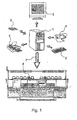
- Fig. 1 shows a possible configuration of a knitted product design device according to the invention with a computer 1, a monitor 3 as a display device and a keyboard 2 and a graphics tablet 4 as input devices.
- a computer 1 a monitor 3 as a display device and a keyboard 2 and a graphics tablet 4 as input devices.
- an external mass storage 6 and a printer 5 are connected to the computer 1 as a further display device.
- the control data generated by the design device are forwarded in the example shown to a flat knitting machine 8, as indicated by an arrow 7.
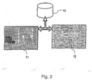
- Fig. 2 illustrates the two different design images that can be displayed on the display device 3 of the design system. It is a mesh image representation 11 and a yarn guide 12 of the mesh product. Both representations 11 and 12 are generated from data of a common memory 10, which is symbolically indicated here. Even when editing and changing one of the two representations 11 or 12, the same data record on the memory 10 is changed in each case. This makes it possible to mitzuver Sn the other representation simultaneously when changing one of the representations 11 or 12.
- Fig. 3 is the monitor 3 off Fig. 1 shown enlarged.
- a plurality of windows 20, 21, 22, 23 are displayed, wherein the windows 20, 21 mesh images and the windows 22, 23 contain thread representations.
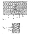
- Fig. 4 shows a section of a mesh image representation, from which the realism of this representation becomes clear.
- Various elements are shown, such as a legal mesh 30, a legal mesh 31 pulled up over two mesh heights, a right-hand stitch 32, which is looped over to the left, and a stitch 33, which is looped over to the right.
- the mesh 34 is a legal mesh that is pulled up over three mesh heights. All stitches are shown in three dimensions and can of course also be colored, the color suitably corresponds to the color of the knitting thread used.
- Fig. 5 shows the mesh image representation of a peripheral region of a mesh product. Two right-stitches 35 and 36 are connected by a connection loop 37. This corresponds to the representation in Fig. 5 exactly the actual thread course of the associated knitted piece.
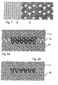
- FIG. 6 Figure 12 shows the stitched image representation of a mesh product having a mesh overcross in two different display modes.
- Fig. 6 a Only the actually intersecting stitches are drawn obliquely to the vertical, while all other stitches, in particular those immediately below the intersecting stitches 40 and 41 are located completely unchanged.
- Fig. 6b the circumstances displayed more realistically.
- the actually intersecting stitches run obliquely to the vertical, but also the adjacent stitches, such as the stitches 40 'and 41', as is the case in the real knitted piece due to the forces acting on it through the mesh intersection.
- Fig. 7 the mesh image representation of a knit fabric is shown with meshes of different sizes and yarn counts. Again, the transition between the small, made with fine yarn right meshes 45 and the large, made with coarser yarn stitches 46 is carried out close to reality.
- Fig. 8 relates to a mesh image representation of a knitted fabric with a dark-drawn wave application 51.
- the two knitting rows of the wave application 51 are shown in normal size and the stitches 52 formed before and after the application 51 are shown drawn in the length.
- Fig. 8 a) is thus a rather theoretical representation, but shows the application 51 itself very well.
- Fig. 8b) however, a more realistic representation has been chosen.
- the two courses of the wave application 51 ' are pushed together here and the remaining stitches 50' shown in their original size and unstretched.
- the design device includes means for graphically equalizing and superposing meshes and courses.
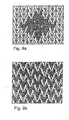
- Fig. 9 a shows the front of a two-color jacquard knitted mesh and Fig. 9b) the back of the associated knit. It is possible to display both representations together on the screen of the monitor 3.
- Fig. 10 Two different ways of displaying a tipping area with mesh symbols are shown.
- the region 60 is the knit region immediately before the first spandrel region 61, while the region 64 is the spandex region subsequent to the second spandex region 63.
- the two Spickel Stude 61 and 63 are separated by a region 62 full knit width.
- the stitches 65 and 66 in the tucking regions 61 and 63 which in the manufacture of the tipping region depend on needles which temporarily do not take part in the knitting process of the knitting and knitting machine during the tying operation, are shown drawn out.
- the elongation extends over as many knitting rows as the associated needle of the respective stitch does not participate in the knitting process.
- the stitches in the intermediate region 62 ' run obliquely, while all stitches in the spatter regions 61' and 63 'are shown in undistorted size.
- Fig. 11 shows a first threadline representation of a 2x3 braid knit.
- the rows 1, 2, 4 and 8 contain knitting information for stitch formation in the front and rear needle bed V, H of a flat knitting machine.
- Rows 3 and 5 details of transfers of stitches of the needles 9, 10 and 11 or of 6, 7 and 8 from the front needle bed V to the rear needle bed H are shown.
- Rows 6 and 7 include needle bed offset and tag details.
- the stitches of the needles 6, 7 and 8 are offset from the rear needle bed H by three stitches to the right and transferred to the front needle bed V.
- row 7 the transfer of the stitches of the needles 9, 10 and 11 from the back needle bed H is shown offset by three stitches to the left on the front needle bed V.
- the yarn guide is no longer realistic, but is generated by symbols.
- the threadline representation corresponds more to the operations that the knitting or knitting machine for making the mesh product must perform.
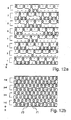
- FIG. 12 Two different possibilities of the threadline representations of a two-color jacquard knit are shown.
- Fig. 12 a) shows for each color of the two-color jacquard knit a separate knitting row, wherein the rows 1, 3, 5 and 7 of the first color and the rows 2, 4, 6 and 8 of the second color are assigned.
- Fig. 12b) in each case two of the knitting rows are made Fig. 12 a) superimposed and thus form a visual knitting series, ie a row of knitting, as it subsequently appears on the finished product.
- the stitches 70 are stitches formed in the first color and the stitches 71 are stitches formed in the second color.
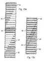
- Fig. 13 shows two ways of yarn path representation of Spickel Studen a knitted piece.
- a first spandex area 81 follows, in which fewer and fewer needles are involved in the knitting process. This is followed by a knit area 82 in full knit width, followed by another spandex area 83, in which increasingly more knitting needles participate in the knitting process until the full knit width is reached again in area 84.
- the representation in Fig. 13b) is closer to reality.
- the stitches of the intermediate region 82 ' run obliquely to the knitting direction, as they subsequently appear in the finished fabric.
- the remaining areas 80 ', 81', 83 'and 84' remain opposite in their representation Fig. 13 a) unchanged.
- Fig. 14 a illustrates the insertion of a knitting module 110 bordered by a thick black line into a basic knit 100.
- the border stitches of the knitting module 110 to the basic knit 100 are designated by 111, while the boundary stitches of the basic knit 100 to the knitting module 110 are designated by 101.
- changes in these limit stitches 101 and / or 111 may be necessary beforehand, so that the knitting module 110 can be correctly integrated into the basic knit 100.
- a stylized template 200 is indicated for any boundary mesh 101 or 111.
- the symbol 201 indicates the operation of the needle on the front needle bed V, while the icon 203 is the operation of the needle on the back needle bed H.
- the slash 202 serves as a pure separator between the symbols 201 and 203 for front and rear needle bed V, H. Fig. 14b) However, not only contains the information for a border mesh 200, but in an AND operation also knitting information for adjacent border needles 200 'and 200''.
- the knitting module 110 has now been inserted into the basic knit 100.
- the limit needle 5/5 of the basic knit 100 here requires an entire limit module 300, which modifies the basic knit to be able to correctly integrate the knit module 110 into the basic knit 100.
- the module 300 extends over the three needles 5/5, 4/5 and 3/5.
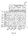
- Fig. 16 shows an input mask of a jacquard generator with which a three-color jacquard knit can be designed.
- the columns 410, 420 and 430 of the mask 400 are associated with the three colors.
- the pattern of each color selected here extends across two needles in width, for which reason the columns 410, 420 and 430 are again divided into two subcolumns 411, 412; 421, 422; 431, 432 are divided.
- Lines 440 and 450 are the two rows of the jacquard pattern. These two rows repeat over the height of the knitted piece over and over again.
- Each of the lines 440, 450 is again divided into three sub-lines 441 to 443 and 451 to 453 corresponding to the three colors of the knitting threads used.
- a knitting module 510 is shown, which is composed of several components, namely a middle field 500, edge fields 505, 506, 507 and 508 and corner fields 501, 502, 503 and 504.
- the knitting module 510 is particularly suitable for expansion, ie enlargement in a knitted piece, as in FIG Fig. 17b) is shown.
- the center panel 500 is multiplied according to the desired size of the entire area and the edge areas 505, 506, 507 and 508 extended accordingly.
- the corner pieces 501, 502, 503 and 504 remain unchanged, but are mitverschoben.
- the illustrated design and presentation possibilities of the knitting product design device according to the invention are merely exemplary. It can be entered into the system and other relevant for the design of a mesh product of any shape and pattern specifications and processed. In addition, the design device is not only suitable for designing garments, but also technical garments.
Landscapes
- Engineering & Computer Science (AREA)
- Textile Engineering (AREA)
- Knitting Machines (AREA)
- Knitting Of Fabric (AREA)
- Filtering Materials (AREA)
- Treatment Of Fiber Materials (AREA)
Claims (22)
- Dispositif pour concevoir des articles de bonneterie fabriqués sur une machine à tricoter ou sur un métier rectiligne, comportant au moins un dispositif de sauvegarde (6, 10) destiné à enregistrer les données nécessaires pour fabriquer l'article de bonneterie sur la machine à tricoter ou sur le métier rectiligne (8), au moins un dispositif d'affichage (3, 5) destiné à représenter des aspects de conception de l'article de bonneterie et au moins un dispositif de saisie (2, 4) destiné à modifier les aspects de conception, caractérisé en ce que l'on peut représenter sous forme d'aspects de conception au moins une représentation de l'aspect des mailles (11, 20, 21) et une représentation du parcours du fil (12, 22, 23) de l'article de bonneterie et qu'on peut les modifier par le dispositif de saisie (2, 4) au moins au nombre d'un, le dispositif de conception modifiant en même temps les autres représentations (11, 20, 21 ; 12, 22, 23) de façon correspondante lorsqu'on modifie une des représentations (11, 20, 21 ; 12, 22, 23) et l'on peut représenter en même temps sur le dispositif d'affichage (3, 5) au moins au nombre d'un la représentation de l'aspect des mailles (11, 20, 21) et la représentation du parcours du fil (12, 22, 23).
- Dispositif selon la revendication 1, caractérisé en ce que l'on peut représenter en même temps sur le dispositif d'affichage (3, 5) au moins au nombre d'un plusieurs sections de l'article de bonneterie en représentation de l'aspect des mailles (11, 20, 21) et/ou en représentation du parcours du fil (12, 22, 23).
- Dispositif selon l'une des revendications 1 à 2, caractérisé en ce que l'on peut représenter sur le dispositif d'affichage (3, 5) au moins au nombre d'un l'avant et l'arrière de l'article de bonneterie en représentation de l'aspect des mailles (11, 20, 21) et/ou en représentation du parcours du fil (12, 22, 23).
- Dispositif selon l'une des revendications 1 à 3, caractérisé en ce que la représentation de l'aspect des mailles (11, 20, 21) contient une représentation en trois dimensions proche de la réalité de tous les éléments d'un article de bonneterie, comme des mailles (30 à 36, 40, 41, 40', 41', 45, 46, 52), une retenue ou un flottage.
- Dispositif selon l'une des revendications 1 à 4, caractérisé en ce que, pour chaque position d'aiguille de l'article de bonneterie, l'on peut indiquer et modifier le type, la forme et la taille de la maille (30 à 36, 40, 41, 40', 41', 45, 46, 52) dans la représentation de l'aspect des mailles (11, 20, 21) à l'aide du dispositif de saisie (2, 4) au moins au nombre d'un.
- Dispositif selon l'une des revendications 1 à 5, caractérisé en ce qu'il présente des dispositifs destinés à calculer et à reproduire la forme des mailles en fonction du type, de la forme et de la taille des mailles voisines et en fonction des propriétés des fils à tricoter utilisés.
- Dispositif selon l'une des revendications 1 à 6, caractérisé en ce que la représentation du parcours du fil (12, 22, 32) présente des symboles pour tous les éléments de l'article de bonneterie, comme des mailles (462, 463), une retenue ou un flottage, ainsi que pour les aiguilles de la machine à tricoter ou du métier rectiligne (8) et leurs fonctionnalités, comme le fait de tricoter, de ne pas tricoter, de transférer, de reprendre et de rabattre etc., et de préférence des symboles pour des paramètres de la machine à tricoter ou du métier rectiligne (8), comme des mouvements du guide-fil, du chariot, l'enroulement du tissu, le décalage des fontures, etc.
- Dispositif selon l'une des revendications 1 à 7, caractérisé en ce qu'il présente des dispositifs destinés à combiner des groupes de symboles d'une représentation du parcours du fil (12, 22, 23) d'un article de bonneterie pour obtenir des modules et des dispositifs destinés à combiner des groupes de mailles d'une représentation de l'aspect des mailles (11, 20, 21) d'un article de bonneterie pour obtenir des modules (110, 510) et des dispositifs de sauvegarde (6, 10) destinés à enregistrer ces modules.
- Dispositif selon la revendication 8, caractérisé en ce qu'il présente des dispositifs destinés à relier des modules (110, 510) correctement selon la technique de maillage, lorsqu'on les utilise dans la représentation de l'aspect des mailles (11, 20, 21) et/ou dans la représentation du parcours du fil (12, 22, 23) d'un article de bonneterie.
- Dispositif selon la revendication 8 ou 9, caractérisé en ce qu'il présente des dispositifs destinés à relier des modules (110, 510) quelconques dans la représentation de l'aspect des mailles et/ou dans la représentation du parcours du fil (11, 20, 21 ; 12, 22, 23) d'un article de bonneterie selon un type de liaison quelconque.
- Dispositif selon l'une des revendications 8 à 10, caractérisé en ce qu'il présente des dispositifs destinés à définir des modules d'interface entre la représentation de l'aspect des mailles ou la représentation du parcours du fil d'un module de tricot et la représentation de l'aspect des mailles ou la représentation du parcours du fil d'un article de bonneterie.
- Dispositif selon l'une des revendications 1 à 11, caractérisé en ce qu'il présente des dispositifs destinés à superposer plusieurs rangées de tricot d'une représentation du parcours du fil (12, 22, 23) et/ou à rassembler plusieurs rangées de tricot d'une représentation de l'aspect des mailles (11, 20, 21) pour obtenir une rangée de tricot.
- Dispositif selon l'une des revendications 1 à 12, caractérisé en ce qu'il présente des dispositifs destinés à corriger graphiquement des rangées de tricot rassemblées dans la représentation de l'aspect des mailles (11, 20, 21) ou des rangées de tricot superposées dans la représentation du parcours du fil (12, 22, 23) sur le dispositif d'affichage (3, 5) au moins au nombre d'un.
- Dispositif selon l'une des revendications 8 à 13, caractérisé en ce qu'il présente des dispositifs destinés à démultiplier et/ou à inverser des modules (110, 510) sur le dispositif d'affichage (3, 5) au moins au nombre d'un.
- Dispositif selon l'une des revendications 8 à 14, caractérisé en ce qu'il présente des dispositifs destinés à agrandir des modules (110, 510) sur le dispositif d'affichage (3, 5) au moins au nombre d'un.
- Dispositif selon l'une des revendications 1 à 15, caractérisé en ce qu'il présente des zones de sauvegarde (6, 10) comportant des données pour des structures de liaison Jacquard prédéterminées dans la représentation de l'aspect des mailles et la représentation du parcours du fil (11, 20, 21 ; 12, 22, 23).
- Dispositif selon l'une des revendications 1 à 16, caractérisé en ce qu'il présente un générateur Jacquard destiné à concevoir la structure de liaison de la face Jacquard visible à la face Jacquard arrière d'un article de bonneterie dans la représentation de l'aspect des mailles et/ou la représentation du parcours du fil (11, 20, 21 ; 12, 22, 23).
- Dispositif selon l'une des revendications 1 à 17, caractérisé en ce qu'il présente un dispositif interactif pour agir sur la conversion des aspects de conception de l'article de bonneterie en données de commande pour la machine à tricoter ou le métier rectiligne (8) par l'intermédiaire du dispositif de saisie (2, 4) au moins au nombre d'un.
- Dispositif selon la revendication 18, caractérisé en ce qu'il présente des dispositifs de sauvegarde (6, 10) destinés à enregistrer les algorithmes de conversion, fréquemment utilisés et indiqués par le dispositif interactif, entre des aspects de conception de l'article de bonneterie et des données de commande pour la machine à tricoter ou le métier rectiligne (8).
- Machine à tricoter ou métier rectiligne comportant un dispositif de conception selon l'une des revendications 1 à 8.
- Procédé pour concevoir des articles de bonneterie fabriqués sur une machine à tricoter ou sur un métier rectiligne, caractérisé en ce que l'article de bonneterie est au moins représenté en représentation de l'aspect des mailles (11. 20, 21) et en représentation du parcours du fil (12, 22, 23), sur un dispositif d'affichage (3, 5) et les autres représentations (11, 20, 21; 12, 22, 23) sont en même temps modifiées par un dispositif de saisie (2, 4) lorsqu'on modifie chacune des représentations (11, 20, 21; 12, 22, 23).
- Procédé selon la revendication 22, caractérisé en ce que la représentation de l'aspect des mailles (11, 20, 21) et la représentation du parcours du fil (12, 22, 23) sont chacune transformées en données de conception pour l'article de bonneterie et sont sauvegardées dans une unité (10) commune de sauvegarde.
Applications Claiming Priority (2)
| Application Number | Priority Date | Filing Date | Title |
|---|---|---|---|
| DE19901542 | 1999-01-16 | ||
| DE19901542A DE19901542C2 (de) | 1999-01-16 | 1999-01-16 | Einrichtung zum Entwurf von auf einer Strick- oder Wirkmaschine hergestellten Maschenerzeugnissen |
Publications (4)
| Publication Number | Publication Date |
|---|---|
| EP1020554A2 EP1020554A2 (fr) | 2000-07-19 |
| EP1020554A3 EP1020554A3 (fr) | 2001-01-10 |
| EP1020554B1 EP1020554B1 (fr) | 2004-07-21 |
| EP1020554B2 true EP1020554B2 (fr) | 2009-07-22 |
Family
ID=7894466
Family Applications (1)
| Application Number | Title | Priority Date | Filing Date |
|---|---|---|---|
| EP00100529A Expired - Lifetime EP1020554B2 (fr) | 1999-01-16 | 2000-01-12 | Dispositif de conception d'articles à mailles produits dans des machines à tricoter |
Country Status (7)
| Country | Link |
|---|---|
| US (1) | US6611730B1 (fr) |
| EP (1) | EP1020554B2 (fr) |
| CN (1) | CN1238582C (fr) |
| AT (1) | ATE271620T1 (fr) |
| DE (2) | DE19901542C2 (fr) |
| ES (1) | ES2223319T3 (fr) |
| PT (1) | PT1020554E (fr) |
Families Citing this family (38)
| Publication number | Priority date | Publication date | Assignee | Title |
|---|---|---|---|---|
| US20020057289A1 (en) * | 2000-11-16 | 2002-05-16 | Jerry Crawford | User station providing localized manufacturing for personalized products |
| DE10131045A1 (de) * | 2001-06-29 | 2003-01-09 | Achim Fricker | Konfektioniervorrichtung |
| DE60238634D1 (de) * | 2001-10-05 | 2011-01-27 | Shima Seiki Mfg | Strickentwurfsverfahren und einheit |
| EP1445714A4 (fr) * | 2001-10-05 | 2008-08-13 | Shima Seiki Mfg | Procede et dispositif de dessin de tricot |
| EP1300498B1 (fr) * | 2001-10-06 | 2008-04-16 | H. Stoll GmbH & Co. | Procédé et dispositif pour la conception de tricots tubulaires tricotés sur un métier rectiligne |
| GB2399095A (en) * | 2003-03-07 | 2004-09-08 | Lee Sara Corp | Electronic patterning on a knitting machine |
| JP4237753B2 (ja) * | 2003-04-15 | 2009-03-11 | 株式会社島精機製作所 | ニットデザイン方法とその装置、及びプログラム |
| JP4237601B2 (ja) * | 2003-10-15 | 2009-03-11 | 株式会社島精機製作所 | ループシミュレーション装置とその方法並びにそのプログラム |
| JP4597586B2 (ja) * | 2004-06-07 | 2010-12-15 | 株式会社島精機製作所 | メランジ糸の糸画像作成装置と糸画像作成方法及びそのプログラム |
| JP4366321B2 (ja) * | 2005-02-18 | 2009-11-18 | 株式会社島精機製作所 | ニット製品のデザイン装置とデザイン方法、およびそのプログラム |
| US8135489B2 (en) * | 2005-05-27 | 2012-03-13 | Shima Seiki Manufacturing, Ltd. | Knit simulation device, knit simulation method, and program thereof |
| DE102005050058A1 (de) * | 2005-10-19 | 2007-04-26 | Saurer Gmbh & Co. Kg | Verfahren zur bidirektionalen Übermittlung von Daten zwischen einer oder mehreren Textilmaschinen |
| JP5032995B2 (ja) * | 2005-11-17 | 2012-09-26 | 株式会社島精機製作所 | ニットデザイン装置とニットデザイン方法及びそのプログラム |
| BE1016943A6 (nl) * | 2006-01-13 | 2007-10-02 | Wiele Michel Van De Nv | Werkwijze voor het vermijden van mengcontouren in poolweefsels. |
| JP5089912B2 (ja) * | 2006-04-25 | 2012-12-05 | 豊田通商株式会社 | 編構造モデル生成プログラム、編構造モデル生成装置、及び編構造モデル生成方法 |
| EP2009161B1 (fr) * | 2007-06-29 | 2013-07-17 | H. Stoll GmbH & Co. KG | Dispositif de réalisation destiné à la conception d'articles à mailles |
| JP5330252B2 (ja) * | 2007-09-10 | 2013-10-30 | 株式会社島精機製作所 | ニットデザインでのデバッグ装置とデバッグ方法、デバッグプログラム |
| US7460927B1 (en) * | 2007-12-21 | 2008-12-02 | Freeman Industrial Co., Ltd. | Method of manufacturing knitted fabrics |
| JP5161297B2 (ja) * | 2008-03-12 | 2013-03-13 | 株式会社島精機製作所 | 編地のデザインシステム |
| DE102010053862A1 (de) * | 2010-12-08 | 2012-06-14 | H. Stoll Gmbh & Co. Kg | Simultane Gestricksimulation während der Mustererstellung anhand einer komprimirten Symboldarstellung |
| DE102010053863B4 (de) * | 2010-12-08 | 2012-10-18 | H. Stoll Gmbh & Co. Kg | Entwurfseinrichtung zum Entwurf von auf einer Flachstrickmaschine strickzeitoptimiert hergestellten Gestricken |
| US8726701B2 (en) * | 2011-03-17 | 2014-05-20 | The Moret Group | Method of making a knit apparel with a tie dyed appearance and an apparel made by the method |
| US20140277663A1 (en) * | 2013-03-15 | 2014-09-18 | Neil Rohin Gupta | System and Method for Creating Custom-Fit Apparel Designs |
| ITBS20130068A1 (it) * | 2013-05-16 | 2014-11-17 | Signal S R L | Metodo di programmazione di una macchina tessile |
| US11131045B2 (en) | 2014-09-15 | 2021-09-28 | Nimbly, Inc. | Systems, methods, and software for manufacturing a knitted article |
| US10351982B2 (en) | 2014-09-15 | 2019-07-16 | Appalatch Outdoor Apparel Company | Systems, methods, and software for manufacturing a custom-knitted article |
| US11478033B2 (en) | 2016-11-06 | 2022-10-25 | Global Apparel Partners Inc. | Knitted textile methods |
| US10995433B1 (en) * | 2017-08-31 | 2021-05-04 | Apple Inc. | Custom fabric cases for electronic devices |
| CN112513859A (zh) * | 2018-05-30 | 2021-03-16 | 耐克创新有限合伙公司 | 服装生产系统和方法 |
| US10787756B2 (en) * | 2018-07-24 | 2020-09-29 | Bolt Threads Inc. | Custom sizing system and methods for a knitted garment having radial symmetry |
| JP7152302B2 (ja) * | 2018-12-27 | 2022-10-12 | 株式会社島精機製作所 | 編地のデザインシステム |
| TWI701621B (zh) * | 2019-10-15 | 2020-08-11 | 薩摩亞商紘織國際有限公司 | 結合動態生產及編織機工作管理的系統 |
| CA3196164A1 (fr) * | 2020-10-01 | 2022-04-07 | Delta Galil Industries Ltd. | Systeme et procede de tricotage automatise |
| CN113239418B (zh) * | 2021-05-31 | 2023-08-29 | 福建睿能科技股份有限公司 | 花样制版方法、计算机设备及可读存储介质 |
| CN113378248B (zh) * | 2021-05-31 | 2023-08-15 | 福建睿能科技股份有限公司 | 针织物的制版成型方法、计算机设备及可读存储介质 |
| CN116497514B (zh) * | 2023-03-21 | 2025-04-18 | 佛山市睿宝智能科技有限公司 | 针织机封针方法、装置、设备及存储介质 |
| US12361644B1 (en) * | 2024-10-29 | 2025-07-15 | Global Apparel Partners Inc. | Methods for updating knitting instructions based on physical measurement of knitted article |
| CN120217464B (zh) * | 2025-03-07 | 2025-11-04 | 东莞东兴商标织绣有限公司 | 一种大提花重纬设计自动处理方法及系统 |
Citations (7)
| Publication number | Priority date | Publication date | Assignee | Title |
|---|---|---|---|---|
| JPS59187606A (ja) † | 1983-04-06 | 1984-10-24 | 保利 有薫 | 服地の裁断方法 |
| JPH0844785A (ja) † | 1994-07-28 | 1996-02-16 | Toyobo Co Ltd | 衣服の立体形状形成方法 |
| US5557527A (en) † | 1993-08-31 | 1996-09-17 | Shima Seiki Manufacturing Ltd. | Knit design system and a method for designing knit fabrics |
| JPH08325821A (ja) † | 1995-05-22 | 1996-12-10 | Toyobo Co Ltd | 衣服の製造方法及び着装シミュレーション装置 |
| US5754431A (en) † | 1995-09-18 | 1998-05-19 | Shima Seiki Manufacturing, Ltd. | Method and apparatus for designing a tubular knitted fabric using a flat knitting machine |
| DE19739239C1 (de) † | 1997-09-09 | 1998-10-29 | Stoll & Co H | Verfahren zur Herstellung eines Gestricks, insbesondere auf einer Flachstrickmaschine |
| EP0882825A2 (fr) † | 1997-06-03 | 1998-12-09 | General Motors Corporation | Housse tricotée |
Family Cites Families (7)
| Publication number | Priority date | Publication date | Assignee | Title |
|---|---|---|---|---|
| JPS6071748A (ja) * | 1983-09-27 | 1985-04-23 | 株式会社島アイデア・センタ− | 柄情報の記録装置 |
| DE3630828A1 (de) * | 1986-09-10 | 1988-03-24 | Stoll & Co H | Einrichtung zum darstellen und aufbereiten von mittels einer flachstrickmaschine herzustellenden strickmustern |
| DE4329875A1 (de) * | 1992-11-16 | 1994-05-19 | Schieber Universal Maschf | Einrichtung zur Entwicklung eines Steuerprogramms für eine Strick- oder Wirkmaschine |
| ATE157786T1 (de) * | 1992-11-16 | 1997-09-15 | Schieber Universal Maschf | Einrichtung zur entwicklung eines steuerprogramms für eine strick- oder wirkmaschine |
| DE4401742A1 (de) * | 1993-09-03 | 1995-07-27 | Schieber Universal Maschf | Einrichtung zur Entwicklung eines Steuerprogramms für eine Strick- oder Wirkmaschine |
| DE4431898A1 (de) * | 1994-09-07 | 1996-03-14 | Scheller Gmbh | Einrichtung zur Entwicklung eines Steuerprogramms für eine Strick- oder Wirkmaschine |
| JP3325168B2 (ja) * | 1995-10-16 | 2002-09-17 | 株式会社島精機製作所 | ニットデザイン方法とニットデザイン装置 |
-
1999
- 1999-01-16 DE DE19901542A patent/DE19901542C2/de not_active Expired - Fee Related
-
2000
- 2000-01-12 EP EP00100529A patent/EP1020554B2/fr not_active Expired - Lifetime
- 2000-01-12 ES ES00100529T patent/ES2223319T3/es not_active Expired - Lifetime
- 2000-01-12 DE DE50007097T patent/DE50007097D1/de not_active Expired - Lifetime
- 2000-01-12 AT AT00100529T patent/ATE271620T1/de not_active IP Right Cessation
- 2000-01-12 PT PT00100529T patent/PT1020554E/pt unknown
- 2000-01-14 US US09/483,953 patent/US6611730B1/en not_active Expired - Fee Related
- 2000-01-17 CN CNB001011073A patent/CN1238582C/zh not_active Expired - Lifetime
Patent Citations (7)
| Publication number | Priority date | Publication date | Assignee | Title |
|---|---|---|---|---|
| JPS59187606A (ja) † | 1983-04-06 | 1984-10-24 | 保利 有薫 | 服地の裁断方法 |
| US5557527A (en) † | 1993-08-31 | 1996-09-17 | Shima Seiki Manufacturing Ltd. | Knit design system and a method for designing knit fabrics |
| JPH0844785A (ja) † | 1994-07-28 | 1996-02-16 | Toyobo Co Ltd | 衣服の立体形状形成方法 |
| JPH08325821A (ja) † | 1995-05-22 | 1996-12-10 | Toyobo Co Ltd | 衣服の製造方法及び着装シミュレーション装置 |
| US5754431A (en) † | 1995-09-18 | 1998-05-19 | Shima Seiki Manufacturing, Ltd. | Method and apparatus for designing a tubular knitted fabric using a flat knitting machine |
| EP0882825A2 (fr) † | 1997-06-03 | 1998-12-09 | General Motors Corporation | Housse tricotée |
| DE19739239C1 (de) † | 1997-09-09 | 1998-10-29 | Stoll & Co H | Verfahren zur Herstellung eines Gestricks, insbesondere auf einer Flachstrickmaschine |
Non-Patent Citations (1)
| Title |
|---|
| SHIMA SEIKI EUROPE LTD: "Bierrebi fully automatic cutting room concept", KNITTING INTERNATIONAL, June 1997 (1997-06-01), TONGWELL MILTON KEYNES MK15 8 HP. UK † |
Also Published As
| Publication number | Publication date |
|---|---|
| CN1261112A (zh) | 2000-07-26 |
| ATE271620T1 (de) | 2004-08-15 |
| DE19901542C2 (de) | 2002-10-10 |
| ES2223319T3 (es) | 2005-03-01 |
| US6611730B1 (en) | 2003-08-26 |
| CN1238582C (zh) | 2006-01-25 |
| HK1028431A1 (en) | 2001-02-16 |
| EP1020554B1 (fr) | 2004-07-21 |
| EP1020554A2 (fr) | 2000-07-19 |
| DE50007097D1 (de) | 2004-08-26 |
| EP1020554A3 (fr) | 2001-01-10 |
| DE19901542A1 (de) | 2000-08-17 |
| PT1020554E (pt) | 2004-11-30 |
Similar Documents
| Publication | Publication Date | Title |
|---|---|---|
| EP1020554B2 (fr) | Dispositif de conception d'articles à mailles produits dans des machines à tricoter | |
| DE69223768T2 (de) | Strickentwurfsystem und verfahren zur herstellung von strickdaten dafür | |
| EP1300498B1 (fr) | Procédé et dispositif pour la conception de tricots tubulaires tricotés sur un métier rectiligne | |
| DE69424957T2 (de) | Strickentwurfsystem zum Entwerfen von gestrickten Stoffen | |
| DE3435301C2 (de) | Vorrichtung zum Aufzeichnen von Muster- und Steuerdaten für das Stricken einer Strickware auf einer V-Zweibettflachstrickmaschine | |
| DE69608866T2 (de) | Verfahren zum Entwurf eines rundgestrickten Artikels für eine Flachstrickmaschine und Vorrichtung zur Durchführung des Verfahrens | |
| DE69618735T2 (de) | Verfahren und Vorrichtung zum Entwurf eines Gestricks | |
| DE3215686A1 (de) | Vorrichtung zum anzeigen einer bildlichen darstellung des naehstichmusters fuer eine naehmaschine | |
| DE19717415A1 (de) | Verfahren zur Herstellung von räumlichen, ein- oder mehrflächigen Gestrickstücken auf einer Flachstrickmaschine | |
| DE4228408A1 (de) | Verfahren zur Herstellung eines formgerechten, einstückigen Flachgestricks, für ein mit Ärmeln versehenes Kleidungsstück | |
| EP1148161B1 (fr) | Procédé pour la fabrication de tricot à plusieurs niveaux de tricotage | |
| DE102013019392A1 (de) | Auftrenn-Vermeidungsverfahren für ein Strickgarn | |
| EP0669015B1 (fr) | Dispositif permettant de developper un programme de commande d'une machine a tricoter ou d'un metier a mailler | |
| EP2009161B1 (fr) | Dispositif de réalisation destiné à la conception d'articles à mailles | |
| DE10142241A1 (de) | Nähmaschine | |
| DE4431898A1 (de) | Einrichtung zur Entwicklung eines Steuerprogramms für eine Strick- oder Wirkmaschine | |
| DE102018220133A1 (de) | Strickware-Strickverfahren | |
| DE102013019158A1 (de) | Verfahren zum Stricken eines Schlauchgestricks sowie Schlauchgestrick | |
| DE69109062T2 (de) | Stoff. | |
| EP2484824B1 (fr) | Simulation de textile tricoté simultanée lors de la création de modèles à l'aide d'une représentation de symbole comprimée | |
| DE3871984T2 (de) | Verfahren und vorrichtung zur herstellung von mustern und webmustern und erhaltenes gewebe. | |
| EP1914335B1 (fr) | Procédé pour obtenir un tricot avec de motifs en forme de tresse | |
| DE102010053863B4 (de) | Entwurfseinrichtung zum Entwurf von auf einer Flachstrickmaschine strickzeitoptimiert hergestellten Gestricken | |
| DE102019215586A1 (de) | Verfahren zum stricken eines schlauchgestricks und schlauchgestrick | |
| EP1111109A2 (fr) | Procédé pour la formation de mailles nouveaux dans un métier à tricoter |
Legal Events
| Date | Code | Title | Description |
|---|---|---|---|
| PUAI | Public reference made under article 153(3) epc to a published international application that has entered the european phase |
Free format text: ORIGINAL CODE: 0009012 |
|
| AK | Designated contracting states |
Kind code of ref document: A2 Designated state(s): AT BE CH CY DE DK ES FI FR GB GR IE IT LI LU MC NL PT SE |
|
| AX | Request for extension of the european patent |
Free format text: AL;LT;LV;MK;RO;SI |
|
| PUAL | Search report despatched |
Free format text: ORIGINAL CODE: 0009013 |
|
| AK | Designated contracting states |
Kind code of ref document: A3 Designated state(s): AT BE CH CY DE DK ES FI FR GB GR IE IT LI LU MC NL PT SE |
|
| AX | Request for extension of the european patent |
Free format text: AL;LT;LV;MK;RO;SI |
|
| 17P | Request for examination filed |
Effective date: 20010612 |
|
| AKX | Designation fees paid |
Free format text: AT BE CH CY DE DK ES FI FR GB GR IE IT LI LU MC NL PT SE |
|
| TPAD | Observations filed by third parties |
Free format text: ORIGINAL CODE: EPIDOS TIPA |
|
| 17Q | First examination report despatched |
Effective date: 20030620 |
|
| GRAP | Despatch of communication of intention to grant a patent |
Free format text: ORIGINAL CODE: EPIDOSNIGR1 |
|
| GRAS | Grant fee paid |
Free format text: ORIGINAL CODE: EPIDOSNIGR3 |
|
| GRAA | (expected) grant |
Free format text: ORIGINAL CODE: 0009210 |
|
| AK | Designated contracting states |
Kind code of ref document: B1 Designated state(s): AT BE CH CY DE DK ES FI FR GB GR IE IT LI LU MC NL PT SE |
|
| REG | Reference to a national code |
Ref country code: GB Ref legal event code: FG4D Free format text: NOT ENGLISH |
|
| REG | Reference to a national code |
Ref country code: CH Ref legal event code: EP |
|
| REG | Reference to a national code |
Ref country code: CH Ref legal event code: PK Free format text: DIE BENENNUNG CH/LI WURDE VOR ERTEILUNG ZURUECKGENOMMEN. |
|
| RBV | Designated contracting states (corrected) |
Designated state(s): BE DE ES FR GR IT PT |
|
| REG | Reference to a national code |
Ref country code: IE Ref legal event code: FG4D Free format text: GERMAN |
|
| REF | Corresponds to: |
Ref document number: 50007097 Country of ref document: DE Date of ref document: 20040826 Kind code of ref document: P |
|
| NLXE | Nl: other communications concerning ep-patents (part 3 heading xe) |
Free format text: PAT. BUL. 09/2004: PATENTNUMBER 1020554 SHOULD BE DELETED (SEE EUROPEAN PATENT BULLETIN 20040818/34) |
|
| REG | Reference to a national code |
Ref country code: GR Ref legal event code: EP Ref document number: 20040402909 Country of ref document: GR |
|
| REG | Reference to a national code |
Ref country code: PT Ref legal event code: SC4A Free format text: AVAILABILITY OF NATIONAL TRANSLATION Effective date: 20041015 |
|
| PGFP | Annual fee paid to national office [announced via postgrant information from national office to epo] |
Ref country code: PT Payment date: 20041214 Year of fee payment: 6 |
|
| PGFP | Annual fee paid to national office [announced via postgrant information from national office to epo] |
Ref country code: BE Payment date: 20041216 Year of fee payment: 6 |
|
| PGFP | Annual fee paid to national office [announced via postgrant information from national office to epo] |
Ref country code: FR Payment date: 20041223 Year of fee payment: 6 |
|
| PG25 | Lapsed in a contracting state [announced via postgrant information from national office to epo] |
Ref country code: IT Free format text: LAPSE BECAUSE OF NON-PAYMENT OF DUE FEES Effective date: 20050112 |
|
| PGFP | Annual fee paid to national office [announced via postgrant information from national office to epo] |
Ref country code: GR Payment date: 20050126 Year of fee payment: 6 |
|
| REG | Reference to a national code |
Ref country code: ES Ref legal event code: FG2A Ref document number: 2223319 Country of ref document: ES Kind code of ref document: T3 |
|
| PLAQ | Examination of admissibility of opposition: information related to despatch of communication + time limit deleted |
Free format text: ORIGINAL CODE: EPIDOSDOPE2 |
|
| PLBQ | Unpublished change to opponent data |
Free format text: ORIGINAL CODE: EPIDOS OPPO |
|
| PLAQ | Examination of admissibility of opposition: information related to despatch of communication + time limit deleted |
Free format text: ORIGINAL CODE: EPIDOSDOPE2 |
|
| PLAR | Examination of admissibility of opposition: information related to receipt of reply deleted |
Free format text: ORIGINAL CODE: EPIDOSDOPE4 |
|
| PLBQ | Unpublished change to opponent data |
Free format text: ORIGINAL CODE: EPIDOS OPPO |
|
| PLBI | Opposition filed |
Free format text: ORIGINAL CODE: 0009260 |
|
| ET | Fr: translation filed | ||
| PLAX | Notice of opposition and request to file observation + time limit sent |
Free format text: ORIGINAL CODE: EPIDOSNOBS2 |
|
| 26 | Opposition filed |
Opponent name: SHIMA SEIKI MFG., LTD. Effective date: 20050420 |
|
| NLR1 | Nl: opposition has been filed with the epo |
Opponent name: SHIMA SEIKI MFG., LTD. |
|
| PLBB | Reply of patent proprietor to notice(s) of opposition received |
Free format text: ORIGINAL CODE: EPIDOSNOBS3 |
|
| PG25 | Lapsed in a contracting state [announced via postgrant information from national office to epo] |
Ref country code: BE Free format text: LAPSE BECAUSE OF NON-PAYMENT OF DUE FEES Effective date: 20060131 Ref country code: FR Free format text: LAPSE BECAUSE OF NON-PAYMENT OF DUE FEES Effective date: 20060131 |
|
| PG25 | Lapsed in a contracting state [announced via postgrant information from national office to epo] |
Ref country code: PT Free format text: LAPSE BECAUSE OF NON-PAYMENT OF DUE FEES Effective date: 20060712 |
|
| REG | Reference to a national code |
Ref country code: PT Ref legal event code: MM4A Effective date: 20060712 |
|
| REG | Reference to a national code |
Ref country code: FR Ref legal event code: ST Effective date: 20060929 |
|
| PGFP | Annual fee paid to national office [announced via postgrant information from national office to epo] |
Ref country code: ES Payment date: 20061214 Year of fee payment: 8 |
|
| BERE | Be: lapsed |
Owner name: H. *STOLL G.M.B.H. & CO. Effective date: 20060131 |
|
| PG25 | Lapsed in a contracting state [announced via postgrant information from national office to epo] |
Ref country code: GR Free format text: LAPSE BECAUSE OF NON-PAYMENT OF DUE FEES Effective date: 20060802 |
|
| REG | Reference to a national code |
Ref country code: ES Ref legal event code: FD2A Effective date: 20080114 |
|
| PUAH | Patent maintained in amended form |
Free format text: ORIGINAL CODE: 0009272 |
|
| STAA | Information on the status of an ep patent application or granted ep patent |
Free format text: STATUS: PATENT MAINTAINED AS AMENDED |
|
| 27A | Patent maintained in amended form |
Effective date: 20090722 |
|
| AK | Designated contracting states |
Kind code of ref document: B2 Designated state(s): BE DE ES FR GR IT PT |
|
| PG25 | Lapsed in a contracting state [announced via postgrant information from national office to epo] |
Ref country code: ES Free format text: LAPSE BECAUSE OF NON-PAYMENT OF DUE FEES Effective date: 20080114 |
|
| PGRI | Patent reinstated in contracting state [announced from national office to epo] |
Ref country code: IT Effective date: 20091201 |
|
| PGFP | Annual fee paid to national office [announced via postgrant information from national office to epo] |
Ref country code: DE Payment date: 20130110 Year of fee payment: 14 |
|
| REG | Reference to a national code |
Ref country code: DE Ref legal event code: R119 Ref document number: 50007097 Country of ref document: DE |
|
| REG | Reference to a national code |
Ref country code: DE Ref legal event code: R119 Ref document number: 50007097 Country of ref document: DE Effective date: 20140801 |
|
| PG25 | Lapsed in a contracting state [announced via postgrant information from national office to epo] |
Ref country code: DE Free format text: LAPSE BECAUSE OF NON-PAYMENT OF DUE FEES Effective date: 20140801 |
|
| PGFP | Annual fee paid to national office [announced via postgrant information from national office to epo] |
Ref country code: IT Payment date: 20190121 Year of fee payment: 20 |