EP1017931B1 - capteur pour la determination de l'air aspire par un moteur a combustion interne - Google Patents
capteur pour la determination de l'air aspire par un moteur a combustion interne Download PDFInfo
- Publication number
- EP1017931B1 EP1017931B1 EP98948795A EP98948795A EP1017931B1 EP 1017931 B1 EP1017931 B1 EP 1017931B1 EP 98948795 A EP98948795 A EP 98948795A EP 98948795 A EP98948795 A EP 98948795A EP 1017931 B1 EP1017931 B1 EP 1017931B1
- Authority
- EP
- European Patent Office
- Prior art keywords
- sensor
- air
- air mass
- mass meter
- internal combustion
- Prior art date
- Legal status (The legal status is an assumption and is not a legal conclusion. Google has not performed a legal analysis and makes no representation as to the accuracy of the status listed.)
- Expired - Lifetime
Links
Images

Classifications
-
- F—MECHANICAL ENGINEERING; LIGHTING; HEATING; WEAPONS; BLASTING
- F02—COMBUSTION ENGINES; HOT-GAS OR COMBUSTION-PRODUCT ENGINE PLANTS
- F02D—CONTROLLING COMBUSTION ENGINES
- F02D41/00—Electrical control of supply of combustible mixture or its constituents
- F02D41/24—Electrical control of supply of combustible mixture or its constituents characterised by the use of digital means
- F02D41/26—Electrical control of supply of combustible mixture or its constituents characterised by the use of digital means using computer, e.g. microprocessor
- F02D41/28—Interface circuits
-
- F—MECHANICAL ENGINEERING; LIGHTING; HEATING; WEAPONS; BLASTING
- F02—COMBUSTION ENGINES; HOT-GAS OR COMBUSTION-PRODUCT ENGINE PLANTS
- F02D—CONTROLLING COMBUSTION ENGINES
- F02D41/00—Electrical control of supply of combustible mixture or its constituents
- F02D41/02—Circuit arrangements for generating control signals
- F02D41/18—Circuit arrangements for generating control signals by measuring intake air flow
-
- G—PHYSICS
- G01—MEASURING; TESTING
- G01F—MEASURING VOLUME, VOLUME FLOW, MASS FLOW OR LIQUID LEVEL; METERING BY VOLUME
- G01F1/00—Measuring the volume flow or mass flow of fluid or fluent solid material wherein the fluid passes through a meter in a continuous flow
- G01F1/68—Measuring the volume flow or mass flow of fluid or fluent solid material wherein the fluid passes through a meter in a continuous flow by using thermal effects
- G01F1/684—Structural arrangements; Mounting of elements, e.g. in relation to fluid flow
- G01F1/6845—Micromachined devices
-
- F—MECHANICAL ENGINEERING; LIGHTING; HEATING; WEAPONS; BLASTING
- F02—COMBUSTION ENGINES; HOT-GAS OR COMBUSTION-PRODUCT ENGINE PLANTS
- F02D—CONTROLLING COMBUSTION ENGINES
- F02D2200/00—Input parameters for engine control
- F02D2200/02—Input parameters for engine control the parameters being related to the engine
- F02D2200/04—Engine intake system parameters
- F02D2200/0418—Air humidity
Definitions
- the invention relates to a sensor for Determination of the intake by an internal combustion engine Air, the mass of air from an air mass meter is detected.
- the detected air mass is in an engine control together with others relevant to the combustion process Data such as temperature or temperature Intake manifold pressure, for calculating injection times and the like. processed.
- JP 05 346 336 A is parallel to a signal determined by a volume show sensor Control unit the signal of an air volume corrector sensor, the atmospheric pressure and humidity detected, entered.
- the object of the invention is to achieve this based, a sensor for an internal combustion engine comprising an air mass meter with a sensor element to record the intake air mass improve that in addition to the air mass Moisture and the intake manifold pressure on simple Are detectable.
- This task is performed with a sensor for an internal combustion engine comprising an air mass meter with a Sensor element for recording the intake air mass solved according to the invention in that adjacent to the Air mass meter or its sensor element is a humidity sensor and a pressure sensor and an evaluation circuit for processing the air mass meter or its sensor element, the humidity sensor and the pressure sensor data provided and provided in are arranged in a single housing.
- Such a sensor has the particularly great advantage that in addition to the air mass, its humidity and pressure not only recorded, but also processed in the sensor become. With such a sensor recorded data due to the evaluation circuit arranged in it advantageously via a few connecting lines be transmitted to a control circuit. On Such a sensor is therefore particularly suitable for Connection to a bus system that only has two data lines needed. In addition, such Sensor can be built very compact.
- the air mass meter or Sensor element and the pressure sensor micromechanical Components are. It can be provided that the Sensor element of the air mass meter and the pressure sensor on a chip or a plate-shaped ceramic component are arranged, making not just a special one small design results, but in particular also it is ensured that both the air mass and the Humidity can be recorded practically at the same location. In another advantageous embodiment provided that the air mass meter or its sensor element and the pressure sensor on two spaced apart Chips are arranged. In this case the pressure measurement then over a certain, predetermined Running distance e.g. inside the air mass measuring tube respectively.
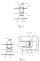
- Fig. 1 is a combination of a known Air mass meter 10 and one from, for example DE 38 29 517 A1 known moisture sensor 20, which in one Intake pipe 30 of an internal combustion engine are arranged shown.
- the air mass meter 10 and the humidity sensor 20 subject of a single housing 25 in which a hybrid space 40 is also provided in the one built in hybrid technology, for example electronic evaluation circuit is housed, which of the air mass meter 10 and the humidity sensor Evaluates 20 recorded data and over lines 42, for example, to a (not shown in FIG. 1) Control unit outputs.
- the air mass meter 10 has, as FIG. 2 shows in more detail, a temperature sensitive sensor means 14, which as Micromechanical component is formed.
- a temperature sensitive sensor means 14 which as Micromechanical component is formed.
- One with one Air flow meter equipped with such a sensor element is known to the expert from DE 44 07 209 C2, the Disclosure expressly part of the present Patent application should be.
- the moisture sensor 20 together with the air mass meter 10 and the evaluation circuit 41 be arranged in a housing 25.
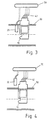
- the moisture it is also possible, in a manner not in accordance with the invention, for the moisture to be outside the actual air mass meter 10 in the Suction pipe 30 arranged to detect moisture sensor 20 whereby those of the air mass meter 10 and the humidity sensor 20 output data supplied to a control unit 70 and processed (see FIG. 3).
- the moisture sensor 20 can also outside in a manner not according to the invention of the suction pipe 30 may be arranged. In this case. he for other control purposes of the vehicle, for example for automatically switching on the windscreen wipers or the lighting or the like can be used (see FIG. 4).
- a pressure sensor 50 is arranged, as shown in FIG. 2 evident. Both the pressure sensor 50 and also the actual air mass meter 12 or Sensor element 14 designed as micromechanical components be on a common chip 13 or ceramic substrate for example in a bypass duct 15 of the air mass meter 10 are arranged. It is beyond that also possible in a manner not according to the invention that the pressure sensor 50 outside the Air mass meter 10 is arranged in the intake manifold 30, as is apparent from Fig. 5.
- the pressure sensor can also consist of a micromechanical component or to known and for example from DE 43 17 312 A1 emerging from the way.
Abstract
Claims (4)
- Capteur pour un moteur à combustion interne regroupant un dispositif de mesure de masse d'air (10) avec un élément de capteur (14) pour déterminer la masse d'air aspirée, avec à côté du dispositif de mesure de masse d'air (10), respectivement de son élément de capteur (14), un capteur d'humidité (20) et un capteur de pression (50) ainsi qu'un circuit de calcul (41) pour traiter les données fournies par le dispositif de mesure de masse d'air (10), respectivement son élément de capteur (14), le capteur d'humidité (20) et le capteur de pression (50), et ces dispositifs soient disposés dans un même boítier (25).
- Capteur selon la revendication 1,
caractérisé en ce que
l'élément de capteur (14) du dispositif de mesure de masse d'air (10) et le capteur de pression (50) sont des pièces micro-mécaniques. - Capteur selon la revendication 2,
caractérisé en ce que
l'élément de capteur (14) du dispositif de mesure de masse d'air (10) et le capteur de pression (50) sont disposés sur une puce (13). - Capteur d'après la revendication 2,
caractérisé en ce que
l'élément de capteur (14) du dispositif de mesure de masse d'air (10) et le capteur de pression (50) sont disposés sur deux puces séparées l'une de l'autre.
Applications Claiming Priority (3)
| Application Number | Priority Date | Filing Date | Title |
|---|---|---|---|
| DE19750496 | 1997-11-14 | ||
| DE19750496A DE19750496A1 (de) | 1997-11-14 | 1997-11-14 | Verfahren zur Bestimmung der von einer Brennkraftmaschine angesaugten Luft und Sensor für eine Brennkraftmaschine |
| PCT/DE1998/002354 WO1999025971A1 (fr) | 1997-11-14 | 1998-08-14 | Procede pour la determination de l'air aspire par un moteur a combustion interne et capteur destine a ce dernier |
Publications (2)
| Publication Number | Publication Date |
|---|---|
| EP1017931A1 EP1017931A1 (fr) | 2000-07-12 |
| EP1017931B1 true EP1017931B1 (fr) | 2003-12-10 |
Family
ID=7848748
Family Applications (1)
| Application Number | Title | Priority Date | Filing Date |
|---|---|---|---|
| EP98948795A Expired - Lifetime EP1017931B1 (fr) | 1997-11-14 | 1998-08-14 | capteur pour la determination de l'air aspire par un moteur a combustion interne |
Country Status (6)
| Country | Link |
|---|---|
| US (1) | US6581447B1 (fr) |
| EP (1) | EP1017931B1 (fr) |
| JP (1) | JP2001509854A (fr) |
| DE (2) | DE19750496A1 (fr) |
| RU (1) | RU2209991C2 (fr) |
| WO (1) | WO1999025971A1 (fr) |
Cited By (5)
| Publication number | Priority date | Publication date | Assignee | Title |
|---|---|---|---|---|
| DE102010043062A1 (de) | 2010-10-28 | 2012-05-03 | Robert Bosch Gmbh | Sensorvorrichtung zur Erfassung einer Strömungseigenschaft eines fluiden Mediums |
| WO2012055622A1 (fr) | 2010-10-28 | 2012-05-03 | Robert Bosch Gmbh | Dispositif capteur pour détecter une propriété d'écoulement d'un milieu fluide |
| WO2013091940A1 (fr) | 2011-12-21 | 2013-06-27 | Robert Bosch Gmbh | Dispositif de capteur pour détecter au moins l'humidité d'un milieu fluide circulant |
| DE102016221678A1 (de) * | 2016-11-04 | 2018-05-09 | Magna BDW technologies GmbH | Vorrichtung zur Herstellung von Druckgussteilen |
| US10994330B2 (en) | 2016-11-04 | 2021-05-04 | Magna BDW technologies GmbH | Device, control system and filter module for producing die-cast parts, and method therefor |
Families Citing this family (31)
| Publication number | Priority date | Publication date | Assignee | Title |
|---|---|---|---|---|
| JP3532776B2 (ja) * | 1998-10-20 | 2004-05-31 | 株式会社日立製作所 | 自動車用センサの取付け構造 |
| DE19964193B4 (de) * | 1999-08-17 | 2009-04-23 | Continental Automotive Gmbh | Luftmassenmesser zum Bestimmen des Umgebungsdruckes bei einer Brennkraftmaschine |
| DE10163751A1 (de) | 2001-12-27 | 2003-07-17 | Bosch Gmbh Robert | Verfahren zum Betreiben einer Brennkraftmaschine |
| US6918362B2 (en) * | 2003-10-02 | 2005-07-19 | Ford Global Technologies, Llc | Engine with variable cam timing and control advantageously using humidity sensor |
| US7195009B2 (en) * | 2003-10-02 | 2007-03-27 | Ford Global Technologies, Llc | Detection of a humidity sensor failure in an internal combustion engine |
| US7246604B2 (en) * | 2003-10-02 | 2007-07-24 | Ford Global Technologies, Llc | Engine control advantageously using humidity |
| US7318409B2 (en) * | 2003-10-02 | 2008-01-15 | Ford Global Technologies, Llc | Vehicle engine control system utilizing humidity sensor |
| DE102004038988B3 (de) * | 2004-08-10 | 2006-01-19 | Siemens Ag | Strömungssensor |
| JP4882732B2 (ja) * | 2006-12-22 | 2012-02-22 | 株式会社デンソー | 半導体装置 |
| JP4416012B2 (ja) * | 2007-06-06 | 2010-02-17 | 株式会社日立製作所 | 吸入空気流量測定装置 |
| EP2055918B1 (fr) * | 2007-10-31 | 2016-06-01 | Fiat Group Automobiles S.p.A. | Procédé et dispositif d'estimation du débit d'air d'entrée dans un moteur à combustion interne |
| JP5178388B2 (ja) * | 2008-08-11 | 2013-04-10 | 日立オートモティブシステムズ株式会社 | 空気流量測定装置 |
| FR2942503B1 (fr) * | 2009-02-23 | 2011-03-04 | Peugeot Citroen Automobiles Sa | Procede et estimateur d'une masse d'air frais dans une chambre de combustion, procede d'estimation de remplissage total, support d'enregistrement pour ces procedes et vehicule equipe de cet estimateur. |
| JP4929333B2 (ja) * | 2009-09-30 | 2012-05-09 | 日立オートモティブシステムズ株式会社 | センサの構造 |
| JP5406674B2 (ja) * | 2009-11-06 | 2014-02-05 | 日立オートモティブシステムズ株式会社 | 熱式流体流量センサおよびその製造方法 |
| JP5445535B2 (ja) * | 2011-08-09 | 2014-03-19 | 株式会社デンソー | 空気流量測定装置 |
| DE102011115590A1 (de) * | 2011-10-11 | 2013-04-11 | GM Global Technology Operations LLC (n. d. Gesetzen des Staates Delaware) | Adaptives Steuerungsverfahren für Scheibenwisch- und Waschanordnungen |
| US9103293B2 (en) * | 2011-12-15 | 2015-08-11 | Ford Global Technologies, Llc | Method for reducing sensitivity for engine scavenging |
| US10066564B2 (en) | 2012-06-07 | 2018-09-04 | GM Global Technology Operations LLC | Humidity determination and compensation systems and methods using an intake oxygen sensor |
| DE102013203142B4 (de) | 2012-03-06 | 2018-03-29 | GM Global Technology Operations LLC (n. d. Ges. d. Staates Delaware) | Motorsteuerverfahren mit Feuchtigkeitssensoren |
| US10202923B2 (en) * | 2012-04-16 | 2019-02-12 | Ford Global Technologies, Llc | Method for estimating intake air humidity |
| DE102012211425A1 (de) * | 2012-07-02 | 2014-01-23 | Robert Bosch Gmbh | Verfahren zur Bestimmung einer Drehzahl eines Verdichters |
| DE102012218758A1 (de) * | 2012-10-15 | 2014-04-17 | Robert Bosch Gmbh | Sensoranordnung zur Bestimmung des Feuchtegehalts eines in einer Hauptströmungsrichtung strömenden fluiden Mediums |
| US9151203B2 (en) | 2012-10-25 | 2015-10-06 | GM Global Technology Operations LLC | Humidity corrections for fuel setpoint adaptation |
| DE102014216482A1 (de) * | 2013-08-22 | 2015-02-26 | Ford Global Technologies, Llc | Verfahren und systeme zur feuchtigkeitsdetektion über einen abgassensor |
| DE102013226140A1 (de) * | 2013-12-17 | 2015-06-18 | Robert Bosch Gmbh | Luftmassenmessvorrichtung, Luftmassenmesssystem und Luftmassenmessverfahren für ein Fahrzeug |
| JP6274021B2 (ja) * | 2014-06-10 | 2018-02-07 | 株式会社デンソー | 湿度測定装置 |
| US9932922B2 (en) * | 2014-10-30 | 2018-04-03 | Ford Global Technologies, Llc | Post-catalyst cylinder imbalance monitor |
| DE102015219501A1 (de) * | 2015-10-08 | 2017-04-13 | Robert Bosch Gmbh | Sensorvorrichtung zur Erfassung mindestens einer Strömungseigenschaft eines fluiden Mediums |
| US10900426B2 (en) | 2016-01-27 | 2021-01-26 | Hitachi Automotive Systems, Ltd. | Control device |
| DE102017211442B4 (de) * | 2017-07-05 | 2020-06-10 | Ford Global Technologies, Llc | Verfahren zum Ermitteln der Umgebungsluftfeuchte eines Kraftfahrzeugs |
Citations (1)
| Publication number | Priority date | Publication date | Assignee | Title |
|---|---|---|---|---|
| EP0352861A2 (fr) * | 1988-07-29 | 1990-01-31 | Magnavox Government and Industrial Electronics Company | Calculateur de gestion d'automobile |
Family Cites Families (11)
| Publication number | Priority date | Publication date | Assignee | Title |
|---|---|---|---|---|
| FR1421273A (fr) * | 1964-01-21 | 1965-12-17 | Inst Francais Du Petrole | Nouveau procédé d'extraction d'hydrocarbures aromatiques |
| GB1543041A (en) * | 1975-02-12 | 1979-03-28 | Lucas Electrical Ltd | Corona discharge fluid flow transducers and fuel injection systems incorporating such transducers |
| DE2851716A1 (de) * | 1978-11-30 | 1980-06-19 | Bosch Gmbh Robert | Messeinrichtung fuer ansaugluft-druck und -temperatur |
| JPS58117333A (ja) * | 1981-12-28 | 1983-07-12 | Mazda Motor Corp | エンジンの制御装置 |
| JPS58155247A (ja) * | 1982-03-09 | 1983-09-14 | Mazda Motor Corp | エンジンの制御装置 |
| JPH03262923A (ja) * | 1990-03-13 | 1991-11-22 | Mitsubishi Heavy Ind Ltd | 環境センサ |
| JP2957769B2 (ja) * | 1991-08-26 | 1999-10-06 | 株式会社日立製作所 | 熱式空気流量計及びエンジン制御装置 |
| JP2908934B2 (ja) * | 1992-06-15 | 1999-06-23 | 三菱電機株式会社 | 吸入空気量値の補正方法 |
| US5267467A (en) * | 1992-07-27 | 1993-12-07 | Ford Motor Company | Mass air flow sensor two temperature production line test apparatus |
| DE4317312A1 (de) | 1993-05-25 | 1994-12-01 | Bosch Gmbh Robert | Drucksensor in einem Kunststoffgehäuse und Verfahren zur Herstellung |
| IT1268604B1 (it) * | 1994-09-30 | 1997-03-06 | Marelli Autronica | Dispositivo sensore multifunzione. |
-
1997
- 1997-11-14 DE DE19750496A patent/DE19750496A1/de not_active Withdrawn
-
1998
- 1998-08-14 EP EP98948795A patent/EP1017931B1/fr not_active Expired - Lifetime
- 1998-08-14 RU RU99117543/06A patent/RU2209991C2/ru active
- 1998-08-14 WO PCT/DE1998/002354 patent/WO1999025971A1/fr active IP Right Grant
- 1998-08-14 DE DE59810415T patent/DE59810415D1/de not_active Expired - Lifetime
- 1998-08-14 US US09/331,016 patent/US6581447B1/en not_active Expired - Lifetime
- 1998-08-14 JP JP52729499A patent/JP2001509854A/ja active Pending
Patent Citations (1)
| Publication number | Priority date | Publication date | Assignee | Title |
|---|---|---|---|---|
| EP0352861A2 (fr) * | 1988-07-29 | 1990-01-31 | Magnavox Government and Industrial Electronics Company | Calculateur de gestion d'automobile |
Cited By (10)
| Publication number | Priority date | Publication date | Assignee | Title |
|---|---|---|---|---|
| DE102010043062A1 (de) | 2010-10-28 | 2012-05-03 | Robert Bosch Gmbh | Sensorvorrichtung zur Erfassung einer Strömungseigenschaft eines fluiden Mediums |
| WO2012055622A1 (fr) | 2010-10-28 | 2012-05-03 | Robert Bosch Gmbh | Dispositif capteur pour détecter une propriété d'écoulement d'un milieu fluide |
| WO2012055621A1 (fr) | 2010-10-28 | 2012-05-03 | Robert Bosch Gmbh | Dispositif capteur pour détecter une propriété d'écoulement d'un milieu fluide |
| DE102010043083A1 (de) | 2010-10-28 | 2012-05-03 | Robert Bosch Gmbh | Sensorvorrichtung zur Erfassung einer Strömungseigenschaft eines fluiden Mediums |
| WO2013091940A1 (fr) | 2011-12-21 | 2013-06-27 | Robert Bosch Gmbh | Dispositif de capteur pour détecter au moins l'humidité d'un milieu fluide circulant |
| DE102011089480A1 (de) | 2011-12-21 | 2013-06-27 | Robert Bosch Gmbh | Sensorvorrichtung zur Erfassung mindestens einer Eigenschaft eines strömenden fluiden Mediums |
| DE102016221678A1 (de) * | 2016-11-04 | 2018-05-09 | Magna BDW technologies GmbH | Vorrichtung zur Herstellung von Druckgussteilen |
| DE102016221678B4 (de) * | 2016-11-04 | 2020-07-16 | Magna BDW technologies GmbH | Vorrichtung zur Herstellung von Druckgussteilen |
| US10994330B2 (en) | 2016-11-04 | 2021-05-04 | Magna BDW technologies GmbH | Device, control system and filter module for producing die-cast parts, and method therefor |
| US10994329B2 (en) | 2016-11-04 | 2021-05-04 | Magna BDW technologies GmbH | Device, control system and filter module for producing die-cast parts, and method therefor |
Also Published As
| Publication number | Publication date |
|---|---|
| DE19750496A1 (de) | 1999-05-20 |
| EP1017931A1 (fr) | 2000-07-12 |
| RU2209991C2 (ru) | 2003-08-10 |
| WO1999025971A1 (fr) | 1999-05-27 |
| US6581447B1 (en) | 2003-06-24 |
| DE59810415D1 (de) | 2004-01-22 |
| JP2001509854A (ja) | 2001-07-24 |
Similar Documents
| Publication | Publication Date | Title |
|---|---|---|
| EP1017931B1 (fr) | capteur pour la determination de l'air aspire par un moteur a combustion interne | |
| DE102007014761B4 (de) | Verfahren zum Betreiben eines sammelnden Partikelsensors und Vorrichtung zur Durchführung des Verfahrens | |
| EP0698408B1 (fr) | Dispositif indicateur du degré de contamination d'un filtre | |
| DE2804850C2 (de) | Vorrichtung zur Messung der Strömungsgeschwindigkeit von Gasen | |
| DE3229411A1 (de) | Elektronische vorrichtung mit selbstueberwachung fuer ein kraftfahrzeug | |
| EP1114244B1 (fr) | Dispositif pour mesurer une grandeur pulsatoire | |
| DE3328450A1 (de) | Verfahren zur ueberpruefung von messfuehlern | |
| DE2800645A1 (de) | Einrichtung zur erfassung von analogdaten fuer digitalrechner | |
| DE3829194A1 (de) | Einrichtung zur messung einer stroemenden luftmenge | |
| DE10129035A1 (de) | Verfahren und Vorrichtung zur Ermittlung einer Temperaturgröße in einer Massenstromleitung | |
| EP0563066B1 (fr) | Dispositif de diagnostic pour la detection de rates de combustion dans un moteur a combustion interne | |
| DE19964193A1 (de) | Luftmassenmesser zum Bestimmen des Umgebungsdruckes bei einer Brennkraftmaschine | |
| DE112017006964T5 (de) | Feuchtigkeitsmessvorrichtung, steuervorrichtung für einen verbrennungsmotor und anomaliedetektionsvorrichtung | |
| DE112017006044T5 (de) | Thermischer Durchflussmengenmesser | |
| DE102014211934A1 (de) | Sensorvorrichtung zur Erfassung einer Feuchte eines fluiden Mediums | |
| EP2795261B1 (fr) | Système de détection | |
| DE19544022A1 (de) | Einrichtung zur Bereitstellung einer Höheninformation in einem Kraftfahrzeug | |
| DE4420193C2 (de) | Anordnung zur Erfassung von Schadstoffen bei Kraftfahrzeugmotoren mit Selbstzündung | |
| DE112018000727T5 (de) | Absolutfeuchtigkeitssensor | |
| DE19534557C2 (de) | Verfahren und Vorrichtung zur Bestimmung des CO¶2¶-Gehaltes in Gasen | |
| DE19601077C2 (de) | Kraftsensor | |
| DE4305934B4 (de) | Anordnung von Sensoren zur Messung der Luftfeuchte | |
| DE19959678A1 (de) | Verfahren zum Abgleich von Sensoren | |
| DE3417495C2 (de) | Verfahren und Vorrichtung zum Bestimmen der von einer Brennkraftmaschine angesaugten Luftmenge | |
| DE10122487B4 (de) | Vorrichtung zur Detektion von Kohlenmonoxid in einem Gasgemisch |
Legal Events
| Date | Code | Title | Description |
|---|---|---|---|
| PUAI | Public reference made under article 153(3) epc to a published international application that has entered the european phase |
Free format text: ORIGINAL CODE: 0009012 |
|
| 17P | Request for examination filed |
Effective date: 19991129 |
|
| AK | Designated contracting states |
Kind code of ref document: A1 Designated state(s): DE FR GB |
|
| 17Q | First examination report despatched |
Effective date: 20021008 |
|
| GRAH | Despatch of communication of intention to grant a patent |
Free format text: ORIGINAL CODE: EPIDOS IGRA |
|
| RTI1 | Title (correction) |
Free format text: SENSOR FOR DETERMINING THE AIR INDUCED BY AN INTERNAL COMBUSTION ENGINE |
|
| RTI1 | Title (correction) |
Free format text: SENSOR FOR DETERMINING THE AIR INDUCED BY AN INTERNAL COMBUSTION ENGINE |
|
| GRAS | Grant fee paid |
Free format text: ORIGINAL CODE: EPIDOSNIGR3 |
|
| GRAA | (expected) grant |
Free format text: ORIGINAL CODE: 0009210 |
|
| AK | Designated contracting states |
Kind code of ref document: B1 Designated state(s): DE FR GB |
|
| REG | Reference to a national code |
Ref country code: GB Ref legal event code: FG4D Free format text: NOT ENGLISH |
|
| REF | Corresponds to: |
Ref document number: 59810415 Country of ref document: DE Date of ref document: 20040122 Kind code of ref document: P |
|
| GBT | Gb: translation of ep patent filed (gb section 77(6)(a)/1977) |
Effective date: 20040301 |
|
| ET | Fr: translation filed | ||
| PLBE | No opposition filed within time limit |
Free format text: ORIGINAL CODE: 0009261 |
|
| STAA | Information on the status of an ep patent application or granted ep patent |
Free format text: STATUS: NO OPPOSITION FILED WITHIN TIME LIMIT |
|
| 26N | No opposition filed |
Effective date: 20040913 |
|
| REG | Reference to a national code |
Ref country code: FR Ref legal event code: PLFP Year of fee payment: 19 |
|
| REG | Reference to a national code |
Ref country code: FR Ref legal event code: PLFP Year of fee payment: 20 |
|
| PGFP | Annual fee paid to national office [announced via postgrant information from national office to epo] |
Ref country code: GB Payment date: 20170824 Year of fee payment: 20 Ref country code: FR Payment date: 20170823 Year of fee payment: 20 |
|
| PGFP | Annual fee paid to national office [announced via postgrant information from national office to epo] |
Ref country code: DE Payment date: 20171026 Year of fee payment: 20 |
|
| REG | Reference to a national code |
Ref country code: DE Ref legal event code: R071 Ref document number: 59810415 Country of ref document: DE |
|
| REG | Reference to a national code |
Ref country code: GB Ref legal event code: PE20 Expiry date: 20180813 |
|
| PG25 | Lapsed in a contracting state [announced via postgrant information from national office to epo] |
Ref country code: GB Free format text: LAPSE BECAUSE OF EXPIRATION OF PROTECTION Effective date: 20180813 |