EP1017931B1 - sensor for determining the air induced by an internal combustion engine - Google Patents
sensor for determining the air induced by an internal combustion engine Download PDFInfo
- Publication number
- EP1017931B1 EP1017931B1 EP98948795A EP98948795A EP1017931B1 EP 1017931 B1 EP1017931 B1 EP 1017931B1 EP 98948795 A EP98948795 A EP 98948795A EP 98948795 A EP98948795 A EP 98948795A EP 1017931 B1 EP1017931 B1 EP 1017931B1
- Authority
- EP
- European Patent Office
- Prior art keywords
- sensor
- air
- air mass
- mass meter
- internal combustion
- Prior art date
- Legal status (The legal status is an assumption and is not a legal conclusion. Google has not performed a legal analysis and makes no representation as to the accuracy of the status listed.)
- Expired - Lifetime
Links
Images

Classifications
-
- F—MECHANICAL ENGINEERING; LIGHTING; HEATING; WEAPONS; BLASTING
- F02—COMBUSTION ENGINES; HOT-GAS OR COMBUSTION-PRODUCT ENGINE PLANTS
- F02D—CONTROLLING COMBUSTION ENGINES
- F02D41/00—Electrical control of supply of combustible mixture or its constituents
- F02D41/24—Electrical control of supply of combustible mixture or its constituents characterised by the use of digital means
- F02D41/26—Electrical control of supply of combustible mixture or its constituents characterised by the use of digital means using computer, e.g. microprocessor
- F02D41/28—Interface circuits
-
- F—MECHANICAL ENGINEERING; LIGHTING; HEATING; WEAPONS; BLASTING
- F02—COMBUSTION ENGINES; HOT-GAS OR COMBUSTION-PRODUCT ENGINE PLANTS
- F02D—CONTROLLING COMBUSTION ENGINES
- F02D41/00—Electrical control of supply of combustible mixture or its constituents
- F02D41/02—Circuit arrangements for generating control signals
- F02D41/18—Circuit arrangements for generating control signals by measuring intake air flow
-
- G—PHYSICS
- G01—MEASURING; TESTING
- G01F—MEASURING VOLUME, VOLUME FLOW, MASS FLOW OR LIQUID LEVEL; METERING BY VOLUME
- G01F1/00—Measuring the volume flow or mass flow of fluid or fluent solid material wherein the fluid passes through a meter in a continuous flow
- G01F1/68—Measuring the volume flow or mass flow of fluid or fluent solid material wherein the fluid passes through a meter in a continuous flow by using thermal effects
- G01F1/684—Structural arrangements; Mounting of elements, e.g. in relation to fluid flow
- G01F1/6845—Micromachined devices
-
- F—MECHANICAL ENGINEERING; LIGHTING; HEATING; WEAPONS; BLASTING
- F02—COMBUSTION ENGINES; HOT-GAS OR COMBUSTION-PRODUCT ENGINE PLANTS
- F02D—CONTROLLING COMBUSTION ENGINES
- F02D2200/00—Input parameters for engine control
- F02D2200/02—Input parameters for engine control the parameters being related to the engine
- F02D2200/04—Engine intake system parameters
- F02D2200/0418—Air humidity
Definitions
- the invention relates to a sensor for Determination of the intake by an internal combustion engine Air, the mass of air from an air mass meter is detected.
- the detected air mass is in an engine control together with others relevant to the combustion process Data such as temperature or temperature Intake manifold pressure, for calculating injection times and the like. processed.
- JP 05 346 336 A is parallel to a signal determined by a volume show sensor Control unit the signal of an air volume corrector sensor, the atmospheric pressure and humidity detected, entered.
- the object of the invention is to achieve this based, a sensor for an internal combustion engine comprising an air mass meter with a sensor element to record the intake air mass improve that in addition to the air mass Moisture and the intake manifold pressure on simple Are detectable.
- This task is performed with a sensor for an internal combustion engine comprising an air mass meter with a Sensor element for recording the intake air mass solved according to the invention in that adjacent to the Air mass meter or its sensor element is a humidity sensor and a pressure sensor and an evaluation circuit for processing the air mass meter or its sensor element, the humidity sensor and the pressure sensor data provided and provided in are arranged in a single housing.
- Such a sensor has the particularly great advantage that in addition to the air mass, its humidity and pressure not only recorded, but also processed in the sensor become. With such a sensor recorded data due to the evaluation circuit arranged in it advantageously via a few connecting lines be transmitted to a control circuit. On Such a sensor is therefore particularly suitable for Connection to a bus system that only has two data lines needed. In addition, such Sensor can be built very compact.
- the air mass meter or Sensor element and the pressure sensor micromechanical Components are. It can be provided that the Sensor element of the air mass meter and the pressure sensor on a chip or a plate-shaped ceramic component are arranged, making not just a special one small design results, but in particular also it is ensured that both the air mass and the Humidity can be recorded practically at the same location. In another advantageous embodiment provided that the air mass meter or its sensor element and the pressure sensor on two spaced apart Chips are arranged. In this case the pressure measurement then over a certain, predetermined Running distance e.g. inside the air mass measuring tube respectively.
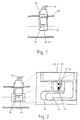
- Fig. 1 is a combination of a known Air mass meter 10 and one from, for example DE 38 29 517 A1 known moisture sensor 20, which in one Intake pipe 30 of an internal combustion engine are arranged shown.
- the air mass meter 10 and the humidity sensor 20 subject of a single housing 25 in which a hybrid space 40 is also provided in the one built in hybrid technology, for example electronic evaluation circuit is housed, which of the air mass meter 10 and the humidity sensor Evaluates 20 recorded data and over lines 42, for example, to a (not shown in FIG. 1) Control unit outputs.
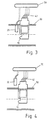
- the air mass meter 10 has, as FIG. 2 shows in more detail, a temperature sensitive sensor means 14, which as Micromechanical component is formed.
- a temperature sensitive sensor means 14 which as Micromechanical component is formed.
- One with one Air flow meter equipped with such a sensor element is known to the expert from DE 44 07 209 C2, the Disclosure expressly part of the present Patent application should be.
- the moisture sensor 20 together with the air mass meter 10 and the evaluation circuit 41 be arranged in a housing 25.
- the moisture it is also possible, in a manner not in accordance with the invention, for the moisture to be outside the actual air mass meter 10 in the Suction pipe 30 arranged to detect moisture sensor 20 whereby those of the air mass meter 10 and the humidity sensor 20 output data supplied to a control unit 70 and processed (see FIG. 3).
- the moisture sensor 20 can also outside in a manner not according to the invention of the suction pipe 30 may be arranged. In this case. he for other control purposes of the vehicle, for example for automatically switching on the windscreen wipers or the lighting or the like can be used (see FIG. 4).
- a pressure sensor 50 is arranged, as shown in FIG. 2 evident. Both the pressure sensor 50 and also the actual air mass meter 12 or Sensor element 14 designed as micromechanical components be on a common chip 13 or ceramic substrate for example in a bypass duct 15 of the air mass meter 10 are arranged. It is beyond that also possible in a manner not according to the invention that the pressure sensor 50 outside the Air mass meter 10 is arranged in the intake manifold 30, as is apparent from Fig. 5.
- the pressure sensor can also consist of a micromechanical component or to known and for example from DE 43 17 312 A1 emerging from the way.
Landscapes
- Engineering & Computer Science (AREA)
- Chemical & Material Sciences (AREA)
- Combustion & Propulsion (AREA)
- Mechanical Engineering (AREA)
- General Engineering & Computer Science (AREA)
- Computer Hardware Design (AREA)
- Microelectronics & Electronic Packaging (AREA)
- Physics & Mathematics (AREA)
- Fluid Mechanics (AREA)
- General Physics & Mathematics (AREA)
- Combined Controls Of Internal Combustion Engines (AREA)
- Measuring Volume Flow (AREA)
Abstract
Description
Die Erfindung betrifft einen Sensor zur Bestimmung der von einer Brennkraftmaschine angesaugten Luft, wobei die Luftmasse von einem Luftmassenmesser erfaßt wird.The invention relates to a sensor for Determination of the intake by an internal combustion engine Air, the mass of air from an air mass meter is detected.
Seit längerem ist es bekannt, die von einer Brennkraftmaschine eines Kraftfahrzeugs angesaugte Luftmasse mittels eines Luftmassenmessers zu erfassen.It has been known for a long time by an internal combustion engine Air mass sucked in by a motor vehicle of an air mass meter.
Die erfaßte Luftmasse wird in einer Motorsteuerung zusammen mit anderen für den Verbrennungsvorgang relevanten Daten, wie beispielsweise die Temperatur oder der Saugrohrdruck, zur Berechnung von Einspritzzeiten u.dgl. verarbeitet. The detected air mass is in an engine control together with others relevant to the combustion process Data such as temperature or temperature Intake manifold pressure, for calculating injection times and the like. processed.
Bei einer sehr feuchten Umgebungsluft wird aufgrund der Luftfeuchtigkeit der von dem Luftmassenmesser erfaßte Luftmassenstrom dadurch verfälscht, daß neben der in der Brennkraftmaschine verbrennbaren Luft gleichzeitig auch Wasserdampf erfaßt wird, der nicht verbrannt werden kann und daher zu sehr nachteiligen Änderungen der Emissionswerte führt . So ist aus der JP 05 05 26 25 A die Messung der Luftmasse und die Kompensation bei Luftfeuchte = änderungen bekannt.At a very humid ambient air is due to the humidity the air mass flow detected by the air mass meter falsified in that in addition to that in the internal combustion engine combustible air at the same time too Water vapor is detected that can not be burned and therefore too adverse changes in emissions leads . This is the measurement from JP 05 05 26 25 A. the air mass and the compensation for air humidity known changes.
Bei der Vorrichtung nach der JP 05 346 336 A wird parallel zu einem von einem volumenshownsensor ermittelten signal einem Steuergerät das signal eines Luftvolumenkorrektorsensors, der Atmosphärendruck und Feuchtigkeit erfaßt, eingegeben. In the device according to JP 05 346 336 A is parallel to a signal determined by a volume show sensor Control unit the signal of an air volume corrector sensor, the atmospheric pressure and humidity detected, entered.
Bekannt ist ebenfalls aus der EP 0 352 861 A mittels Sensoren eine Bestimmung der Luftmasse, der Luftfeuchtigkeit und des Ansaugdruckes.It is also known from EP 0 352 861 A Sensors determine the air mass, the air humidity and the suction pressure.
Der Erfindung liegt die Aufgabe zugrunde, einen Sensor für eine Brennkraftmaschine umfassend einen Luftmassenmesser mit einem Sensorelement zur Erfassung der angesaugten Luftmasse dahingehend zu verbessern, daß neben der Luftmasse auch noch die Feuchtigkeit und der Saugrohrdruck auf einfache Weise erfaßbar sind. The object of the invention is to achieve this based, a sensor for an internal combustion engine comprising an air mass meter with a sensor element to record the intake air mass improve that in addition to the air mass Moisture and the intake manifold pressure on simple Are detectable.
Diese Aufgabe wird bei einem Sensor für eine Brennkraftmaschine umfassend einen Luftmassenmesser mit einem Sensorelement zur Erfassung der angesaugten Luftmasse erfindungsgemäß dadurch gelöst, daß benachbart zu dem Luftmassenmesser bzw. dessen Sensorelement ein Feuchtesensor und ein Drucksensor sowie eine Auswerteschaltung zur Verarbeitung der von dem Luftmassenmesser bzw. dessen Sensorelement, dem Feuchtesensor und dem Drucksensor ausgegebenen Daten vorgesehen und in einem einzigen Gehäuse angeordnet sind.This task is performed with a sensor for an internal combustion engine comprising an air mass meter with a Sensor element for recording the intake air mass solved according to the invention in that adjacent to the Air mass meter or its sensor element is a humidity sensor and a pressure sensor and an evaluation circuit for processing the air mass meter or its sensor element, the humidity sensor and the pressure sensor data provided and provided in are arranged in a single housing.
Ein derartiger Sensor hat den besonders großen Vorteil, daß neben der Luftmasse auch deren Feuchtigkeit und Druck nicht nur erfaßt, sondern auch bereits im Sensor verarbeitet werden. Durch einen solchen Sensor können die erfaßten Daten aufgrund der in ihm angeordneten Auswerteschaltung vorteilhafterweise über wenige Anschlußleitungen an eine Steuerschaltung übermittelt werden. Ein derartiger Sensor eignet sich daher insbesondere auch zum Anschluß an ein Bus-System, welches nur zwei Datenleitungen benötigt. Darüber hinaus kann ein derartiger Sensor sehr kompakt aufgebaut werden.Such a sensor has the particularly great advantage that in addition to the air mass, its humidity and pressure not only recorded, but also processed in the sensor become. With such a sensor recorded data due to the evaluation circuit arranged in it advantageously via a few connecting lines be transmitted to a control circuit. On Such a sensor is therefore particularly suitable for Connection to a bus system that only has two data lines needed. In addition, such Sensor can be built very compact.
So ist beispielsweise bei einer vorteilhaften Ausführungsform vorgesehen, daß der Luftmassenmesser bzw. das Sensorelement und der Drucksensor mikromechanische Bauteile sind. Dabei kann vorgesehen sein, daß das Sensorelement des Luftmassenmessers und der Drucksensor auf einem Chip oder einem plättchenförmigen Keramikbauteil angeordnet sind, wodurch nicht nur eine besonders kleine Bauform resultiert, sondern insbesondere auch sichergestellt ist, daß sowohl die Luftmasse als auch die Luftfeuchtigkeit praktisch am selben Ort erfaßt werden. Bei einer anderen vorteilhaften Ausführungsform ist vorgesehen, daß der Luftmassenmesser bzw. dessen Sensorelement und der Drucksensor auf zwei voneinander beabstandeten Chips angeordnet sind. In diesem Falle kann die Druckmessung dann über eine bestimmte, vorgebbare Laufstrecke z.B. innerhalb des Luftmassenmeßrohrs erfolgen.This is the case, for example, in an advantageous embodiment provided that the air mass meter or Sensor element and the pressure sensor micromechanical Components are. It can be provided that the Sensor element of the air mass meter and the pressure sensor on a chip or a plate-shaped ceramic component are arranged, making not just a special one small design results, but in particular also it is ensured that both the air mass and the Humidity can be recorded practically at the same location. In another advantageous embodiment provided that the air mass meter or its sensor element and the pressure sensor on two spaced apart Chips are arranged. In this case the pressure measurement then over a certain, predetermined Running distance e.g. inside the air mass measuring tube respectively.
Weitere Merkmale und Vorteile der Erfindung sind Gegenstand der nachfolgenden Beschreibung sowie der zeichnerischen Darstellung.Other features and advantages of the invention are the subject the following description and the graphic Presentation.
In der Zeichnung zeigen:
- Fig. 1
- ein Ausführungsbeispiel eines Sensors für eine Brennkraftmaschine, der von der Erfindung Gebrauch macht;
- Fig. 2
- eine weitere Darstellung eines Sensors gemäß Figur 1 für eine Brennkraftmaschine, der von der Erfindung Gebrauch macht;
- Fig. 3 bis Fig. 5
- zeigen sensoren für erlänternde Zwecke.
- Fig. 1
- an embodiment of a sensor for an internal combustion engine, which makes use of the invention;
- Fig. 2
- a further representation of a sensor according to Figure 1 for an internal combustion engine, which makes use of the invention;
- 3 to 5
- show sensors for educational purposes.
In Fig. 1 ist eine Kombination aus einem an sich bekannten
Luftmassenmesser 10 und einem beispielsweise aus der
DE 38 29 517 A1 bekannten Feuchtesensor 20, die in einem
Saugrohr 30 einer Brennkraftmaschine angeordnet sind,
dargestellt. Bei dem in Fig. 1 dargestellten Ausführungsbeispiel
ist der Luftmassenmesser 10 und der Feuchtesensor
20 Gegenstand eines einzigen Gehäuses 25, in dem
darüber hinaus auch ein Hybridraum 40 vorgesehen ist, in
dem eine beispielsweise in Hybridtechnik aufgebaute
elektronische Auswerteschaltung untergebracht ist,
welche die von dem Luftmassenmesser 10 und dem Feuchtigkeitssensor
20 erfaßten Daten auswertet und über Leitungen
42 beispielsweise an ein (in Fig. 1 nicht dargestelltes)
Steuergerät ausgibt.In Fig. 1 is a combination of a known
Der Luftmassenmesser 10 besitzt, wie Fig. 2 näher zeigt,
ein temperaturempfindliches Sensormittel 14, das als
mikromechanisches Bauteil ausgebildet ist. Ein mit einem
derartigen Sensorelement ausgestatteter Luftmassenmesser
ist dem Fachmann aus der DE 44 07 209 C2 bekannt, deren
Offenbarung ausdrücklich Bestandteil der hier vorliegenden
Patentanmeldung sein soll. Selbstverständlich kann
der Luftmassenmesser 10 auch als sogenannter Heißfilm-Luftmassenmesser
aufgebaut sein, der als Sensorelement
ein mit temperaturabhängigen Widerstandsschichten
versehenes plättchenförmiges Keramiksubstrat aufweist,
wie es zum Beispiel aus der DE 36 38 138 A1 hervorgeht.The
Durch die simultane Erfassung der Luftfeuchtigkeit ist bei dem erfaßten Luftmassenstrom der Teil der angesaugten Luft, der von der Brennkraftmaschine verbrennbar ist, von Wasser im gasförmigen Zustand unterscheidbar. Hierdurch wird die Präzision, beispielsweise bei der Berechnung des Lastsignals wesentlich erhöht, da nur die Anteile der erfaßten Luft berücksichtigt werden können.Due to the simultaneous detection of air humidity in the case of the detected air mass flow, the part of the intake Air that is combustible by the internal combustion engine from Distinct water in the gaseous state. hereby is the precision, for example when calculating the Load signal increased significantly because only the proportions of the detected air can be taken into account.
Wie aus Fig. 1 hervorgeht, kann der Feuchtesensor 20
zusammen mit dem Luftmassenmesser 10 und der Auswerteschaltung
41 in einem Gehäuse 25 angeordnet sein.As can be seen from FIG. 1, the
Möglich ist es aber auch, in nicht erfindungsgemäßer Weise die Feuchte durch einen
außerhalb des eigentlichen Luftmassenmessers 10 in dem
Saugrohr 30 angeordneten Feuchtesensor 20 zu erfassen,
wobei die von dem Luftmassenmesser 10 und dem Feuchtesensor
20 ausgegebenen Daten einem Steuergerät 70 zugeführt
und verarbeitet werden (vgl. Fig. 3).However, it is also possible, in a manner not in accordance with the invention, for the moisture to be
outside the actual
Darüber hinaus kann der Feuchtesensor 20 in nicht erfindungsgemäßer Weise auch außerhalb
des Saugrohrs 30 angeordnet sein. In diesem Falle kann. er
für weitere Steuerzwecke des Fahrzeugs, beispielsweise
für das selbsttätige Einschalten der Scheibenwischer oder
der Beleuchtung o.dgl. verwendet werden (vgl. Fig. 4).In addition, the
Neben dem in dem Gehäuse 25 des Luftmassenmessers 10
angeordneten Feuchtesensor 20 ist darüber hinaus auch
ein Drucksensor 50 angeordnet, wie es aus Fig. 2
hervorgeht. Dabei können sowohl der Drucksensor 50 als
auch der eigentliche Luftmassenmesser 12 bzw. sein
Sensorelement 14 als mikromechanische Bauteile ausgeführt
sein, die auf einem gemeinsamen Chip 13 oder Keramiksubstrat
zum Beispiel in einem Bypasskanal 15 des Luftmassenmessers
10 angeordnet sind. Darüber hinaus ist es aber
auch in nicht erfindungsgemäßer Weise möglich, daß der Drucksensor 50 außerhalb des
Luftmassenmessers 10 in dem Saugrohr 30 angeordnet ist,
wie es aus Fig. 5 hervorgeht. Dabei kann der Drucksensor
ebenfalls aus einem mikromechanischen Bauteil bestehen
oder auf an sich bekannte und beispielsweise aus der DE
43 17 312 A1 hervorgehende Weise aufgebaut sein.In addition to that in the
Es versteht sich, daß die in Fig. 2 dargestellte Kombination
von Luftmassenmesser 10 bzw. dessen Sensorelement
14 und Drucksensor 50 auf die im Zusammenhang
mit Fig. 1 beschriebene Weise mit einem Feuchtesensor
20 kombiniert ist. Somit umfaßt der
Sensor für die Brennkraftmaschine einen Luftmassenmesser
10, einen Feuchtesensor 20 und einen Drucksensor
50, wobei dieser Sensor zusammen mit einer Auswerteschaltung
in einem gemeinsamen Gehäuse angeordnet ist.It is understood that the combination shown in Fig. 2
of
Dabei können das Sensorelement 14 des Luftmassenmessers
10, der Feuchtesensor 20 und der Drucksensor 50 auch auf
einen gemeinsamen Chip oder Keramiksubstrat aufgebracht
sein, der sich vorzugsweise im Bypasskanal 15 des
Luftmassenmessers 10 befindet.The sensor element 14 of the air mass meter can
10, the
Claims (4)
- Sensor for an internal combustion engine, comprising an air-mass meter (10) with a sensor element (14) for detecting the induced air mass, there being provided adjacently to the air-mass meter (10) or its sensor element (14) and being arranged in a single housing (25) a moisture sensor (20) and a pressure sensor (50) and also an evaluation circuit (41) for processing the data emitted by the air-mass meter (10) or its sensor element (14), by the moisture sensor (20) and by the pressure sensor (50).
- Sensor according to Claim 1, characterized in that the sensor element (14) of the air-mass meter (10) and the pressure sensor (50) are micromechanical components.
- Sensor according to Claim 2, characterized in that the sensor element (14) of the air-mass meter (10) and the pressure sensor (50) are arranged on a chip (13).
- Sensor according to Claim 2, characterized in that the sensor element (14) of the air-mass meter (10) and the pressure sensor (50) are arranged on two chips spaced apart from one another.
Applications Claiming Priority (3)
| Application Number | Priority Date | Filing Date | Title |
|---|---|---|---|
| DE19750496 | 1997-11-14 | ||
| DE19750496A DE19750496A1 (en) | 1997-11-14 | 1997-11-14 | Method of determining the air induced into an internal combustion engine |
| PCT/DE1998/002354 WO1999025971A1 (en) | 1997-11-14 | 1998-08-14 | Method for determining the air induced by an internal combustion engine and a sensor for an internal combustion engine |
Publications (2)
| Publication Number | Publication Date |
|---|---|
| EP1017931A1 EP1017931A1 (en) | 2000-07-12 |
| EP1017931B1 true EP1017931B1 (en) | 2003-12-10 |
Family
ID=7848748
Family Applications (1)
| Application Number | Title | Priority Date | Filing Date |
|---|---|---|---|
| EP98948795A Expired - Lifetime EP1017931B1 (en) | 1997-11-14 | 1998-08-14 | sensor for determining the air induced by an internal combustion engine |
Country Status (6)
| Country | Link |
|---|---|
| US (1) | US6581447B1 (en) |
| EP (1) | EP1017931B1 (en) |
| JP (1) | JP2001509854A (en) |
| DE (2) | DE19750496A1 (en) |
| RU (1) | RU2209991C2 (en) |
| WO (1) | WO1999025971A1 (en) |
Cited By (5)
| Publication number | Priority date | Publication date | Assignee | Title |
|---|---|---|---|---|
| DE102010043062A1 (en) | 2010-10-28 | 2012-05-03 | Robert Bosch Gmbh | Sensor device for detecting a flow characteristic of a fluid medium |
| WO2012055622A1 (en) | 2010-10-28 | 2012-05-03 | Robert Bosch Gmbh | Sensor device for detecting a flow property of a fluid medium |
| DE102011089480A1 (en) | 2011-12-21 | 2013-06-27 | Robert Bosch Gmbh | Sensor device for detecting at least one property of a flowing fluid medium |
| DE102016221678A1 (en) * | 2016-11-04 | 2018-05-09 | Magna BDW technologies GmbH | Apparatus for the production of die-cast parts |
| US10994330B2 (en) | 2016-11-04 | 2021-05-04 | Magna BDW technologies GmbH | Device, control system and filter module for producing die-cast parts, and method therefor |
Families Citing this family (31)
| Publication number | Priority date | Publication date | Assignee | Title |
|---|---|---|---|---|
| JP3532776B2 (en) * | 1998-10-20 | 2004-05-31 | 株式会社日立製作所 | Mounting structure for automotive sensors |
| DE19964193B4 (en) * | 1999-08-17 | 2009-04-23 | Continental Automotive Gmbh | Air mass meter for determining the ambient pressure in an internal combustion engine |
| DE10163751A1 (en) | 2001-12-27 | 2003-07-17 | Bosch Gmbh Robert | Method for operating an internal combustion engine |
| US7318409B2 (en) * | 2003-10-02 | 2008-01-15 | Ford Global Technologies, Llc | Vehicle engine control system utilizing humidity sensor |
| US7195009B2 (en) * | 2003-10-02 | 2007-03-27 | Ford Global Technologies, Llc | Detection of a humidity sensor failure in an internal combustion engine |
| US6918362B2 (en) * | 2003-10-02 | 2005-07-19 | Ford Global Technologies, Llc | Engine with variable cam timing and control advantageously using humidity sensor |
| US7246604B2 (en) * | 2003-10-02 | 2007-07-24 | Ford Global Technologies, Llc | Engine control advantageously using humidity |
| DE102004038988B3 (en) * | 2004-08-10 | 2006-01-19 | Siemens Ag | Gas mass flow measurement system for various applications has substrate with ceramic particles in organic matrix holding heating elements with temperature sensors |
| JP4882732B2 (en) * | 2006-12-22 | 2012-02-22 | 株式会社デンソー | Semiconductor device |
| JP4416012B2 (en) * | 2007-06-06 | 2010-02-17 | 株式会社日立製作所 | Intake air flow rate measuring device |
| EP2055918B1 (en) * | 2007-10-31 | 2016-06-01 | Fiat Group Automobiles S.p.A. | Method and device for estimating the intake air flow rate in an internal combustion engine |
| JP5178388B2 (en) * | 2008-08-11 | 2013-04-10 | 日立オートモティブシステムズ株式会社 | Air flow measurement device |
| FR2942503B1 (en) * | 2009-02-23 | 2011-03-04 | Peugeot Citroen Automobiles Sa | METHOD AND ESTIMATOR OF FRESH AIR MASS IN A COMBUSTION CHAMBER, TOTAL FILLING ESTIMATING METHOD, RECORDING MEDIUM FOR THESE METHODS AND VEHICLE EQUIPPED WITH SAID ESTIMATOR |
| JP4929333B2 (en) * | 2009-09-30 | 2012-05-09 | 日立オートモティブシステムズ株式会社 | Sensor structure |
| JP5406674B2 (en) * | 2009-11-06 | 2014-02-05 | 日立オートモティブシステムズ株式会社 | Thermal fluid flow sensor and manufacturing method thereof |
| JP5445535B2 (en) * | 2011-08-09 | 2014-03-19 | 株式会社デンソー | Air flow measurement device |
| DE102011115590A1 (en) * | 2011-10-11 | 2013-04-11 | GM Global Technology Operations LLC (n. d. Gesetzen des Staates Delaware) | Adaptive control device for controlling e.g. windscreen wiper arrangement of motor car, has wiper arms mounted with respect to pane, where control device controls vehicle-specific control parameter over climate module of motor car |
| US9103293B2 (en) * | 2011-12-15 | 2015-08-11 | Ford Global Technologies, Llc | Method for reducing sensitivity for engine scavenging |
| DE102013203142B4 (en) | 2012-03-06 | 2018-03-29 | GM Global Technology Operations LLC (n. d. Ges. d. Staates Delaware) | Motor control method with humidity sensors |
| US10066564B2 (en) | 2012-06-07 | 2018-09-04 | GM Global Technology Operations LLC | Humidity determination and compensation systems and methods using an intake oxygen sensor |
| US10202923B2 (en) * | 2012-04-16 | 2019-02-12 | Ford Global Technologies, Llc | Method for estimating intake air humidity |
| DE102012211425A1 (en) * | 2012-07-02 | 2014-01-23 | Robert Bosch Gmbh | Method for determining a speed of a compressor |
| DE102012218758A1 (en) * | 2012-10-15 | 2014-04-17 | Robert Bosch Gmbh | Sensor arrangement for determining the moisture content of a flowing in a main flow fluid medium |
| US9151203B2 (en) | 2012-10-25 | 2015-10-06 | GM Global Technology Operations LLC | Humidity corrections for fuel setpoint adaptation |
| DE102014216482B4 (en) * | 2013-08-22 | 2024-05-29 | Ford Global Technologies, Llc | METHODS AND SYSTEMS FOR MOISTURE DETECTION VIA AN EXHAUST GAS SENSOR |
| DE102013226140A1 (en) * | 2013-12-17 | 2015-06-18 | Robert Bosch Gmbh | Air mass measuring device, air mass measurement system and air mass measurement method for a vehicle |
| JP6274021B2 (en) * | 2014-06-10 | 2018-02-07 | 株式会社デンソー | Humidity measuring device |
| US9932922B2 (en) * | 2014-10-30 | 2018-04-03 | Ford Global Technologies, Llc | Post-catalyst cylinder imbalance monitor |
| DE102015219501A1 (en) * | 2015-10-08 | 2017-04-13 | Robert Bosch Gmbh | Sensor device for detecting at least one flow characteristic of a fluid medium |
| JP6545290B2 (en) * | 2016-01-27 | 2019-07-17 | 日立オートモティブシステムズ株式会社 | Control device |
| DE102017211442B4 (en) * | 2017-07-05 | 2020-06-10 | Ford Global Technologies, Llc | Method for determining the ambient air humidity of a motor vehicle |
Citations (1)
| Publication number | Priority date | Publication date | Assignee | Title |
|---|---|---|---|---|
| EP0352861A2 (en) * | 1988-07-29 | 1990-01-31 | Magnavox Government and Industrial Electronics Company | Vehicle management computer |
Family Cites Families (11)
| Publication number | Priority date | Publication date | Assignee | Title |
|---|---|---|---|---|
| FR1421273A (en) * | 1964-01-21 | 1965-12-17 | Inst Francais Du Petrole | New process for extracting aromatic hydrocarbons |
| GB1543041A (en) * | 1975-02-12 | 1979-03-28 | Lucas Electrical Ltd | Corona discharge fluid flow transducers and fuel injection systems incorporating such transducers |
| DE2851716C2 (en) * | 1978-11-30 | 1987-01-29 | Robert Bosch Gmbh, 7000 Stuttgart | Measuring device for intake air pressure and temperature |
| JPS58117333A (en) * | 1981-12-28 | 1983-07-12 | Mazda Motor Corp | Controller for engine |
| JPS58155247A (en) * | 1982-03-09 | 1983-09-14 | Mazda Motor Corp | Control device of engine |
| JPH03262923A (en) * | 1990-03-13 | 1991-11-22 | Mitsubishi Heavy Ind Ltd | Environment sensor |
| JP2957769B2 (en) * | 1991-08-26 | 1999-10-06 | 株式会社日立製作所 | Thermal air flow meter and engine controller |
| JP2908934B2 (en) * | 1992-06-15 | 1999-06-23 | 三菱電機株式会社 | How to correct the intake air value |
| US5267467A (en) * | 1992-07-27 | 1993-12-07 | Ford Motor Company | Mass air flow sensor two temperature production line test apparatus |
| DE4317312A1 (en) | 1993-05-25 | 1994-12-01 | Bosch Gmbh Robert | Pressure sensor in a plastics housing and method for its production |
| IT1268604B1 (en) * | 1994-09-30 | 1997-03-06 | Marelli Autronica | MULTIFUNCTION SENSOR DEVICE. |
-
1997
- 1997-11-14 DE DE19750496A patent/DE19750496A1/en not_active Withdrawn
-
1998
- 1998-08-14 JP JP52729499A patent/JP2001509854A/en active Pending
- 1998-08-14 RU RU99117543/06A patent/RU2209991C2/en active
- 1998-08-14 US US09/331,016 patent/US6581447B1/en not_active Expired - Lifetime
- 1998-08-14 WO PCT/DE1998/002354 patent/WO1999025971A1/en active IP Right Grant
- 1998-08-14 DE DE59810415T patent/DE59810415D1/en not_active Expired - Lifetime
- 1998-08-14 EP EP98948795A patent/EP1017931B1/en not_active Expired - Lifetime
Patent Citations (1)
| Publication number | Priority date | Publication date | Assignee | Title |
|---|---|---|---|---|
| EP0352861A2 (en) * | 1988-07-29 | 1990-01-31 | Magnavox Government and Industrial Electronics Company | Vehicle management computer |
Cited By (10)
| Publication number | Priority date | Publication date | Assignee | Title |
|---|---|---|---|---|
| DE102010043062A1 (en) | 2010-10-28 | 2012-05-03 | Robert Bosch Gmbh | Sensor device for detecting a flow characteristic of a fluid medium |
| WO2012055622A1 (en) | 2010-10-28 | 2012-05-03 | Robert Bosch Gmbh | Sensor device for detecting a flow property of a fluid medium |
| DE102010043083A1 (en) | 2010-10-28 | 2012-05-03 | Robert Bosch Gmbh | Sensor device for detecting a flow characteristic of a fluid medium |
| WO2012055621A1 (en) | 2010-10-28 | 2012-05-03 | Robert Bosch Gmbh | Sensor device for detecting a flow property of a fluid medium |
| DE102011089480A1 (en) | 2011-12-21 | 2013-06-27 | Robert Bosch Gmbh | Sensor device for detecting at least one property of a flowing fluid medium |
| WO2013091940A1 (en) | 2011-12-21 | 2013-06-27 | Robert Bosch Gmbh | Sensor device for detecting at least the moisture of a flowing fluid medium |
| DE102016221678A1 (en) * | 2016-11-04 | 2018-05-09 | Magna BDW technologies GmbH | Apparatus for the production of die-cast parts |
| DE102016221678B4 (en) * | 2016-11-04 | 2020-07-16 | Magna BDW technologies GmbH | Device for the production of die-cast parts |
| US10994330B2 (en) | 2016-11-04 | 2021-05-04 | Magna BDW technologies GmbH | Device, control system and filter module for producing die-cast parts, and method therefor |
| US10994329B2 (en) | 2016-11-04 | 2021-05-04 | Magna BDW technologies GmbH | Device, control system and filter module for producing die-cast parts, and method therefor |
Also Published As
| Publication number | Publication date |
|---|---|
| EP1017931A1 (en) | 2000-07-12 |
| WO1999025971A1 (en) | 1999-05-27 |
| DE19750496A1 (en) | 1999-05-20 |
| RU2209991C2 (en) | 2003-08-10 |
| US6581447B1 (en) | 2003-06-24 |
| DE59810415D1 (en) | 2004-01-22 |
| JP2001509854A (en) | 2001-07-24 |
Similar Documents
| Publication | Publication Date | Title |
|---|---|---|
| EP1017931B1 (en) | sensor for determining the air induced by an internal combustion engine | |
| DE4435754C2 (en) | Multiple pressure sensor | |
| EP0698408B1 (en) | Device for the indication of the contamination level of a filter | |
| DE102007014761B4 (en) | Method for operating a collecting particle sensor and device for carrying out the method | |
| DE2804850C2 (en) | Device for measuring the flow rate of gases | |
| DE3229411A1 (en) | Electronic device with self-monitoring for a motor vehicle | |
| DE3328450A1 (en) | METHOD FOR CHECKING PROBE | |
| DE2800645A1 (en) | DEVICE FOR ACQUISITION OF ANALOG DATA FOR DIGITAL COMPUTER | |
| DE3829194A1 (en) | DEVICE FOR MEASURING A FLOWING AIR AMOUNT | |
| DE10129035A1 (en) | Inlet temperature measurement system for car engines, estimates effect of exhaust gas addition | |
| DE4112481A1 (en) | METHOD AND DEVICE FOR CHECKING THE FUNCTIONALITY OF A TANK BLEEDING SYSTEM | |
| EP0563066B1 (en) | Diagnostic device for detecting defective combustion in an internal combustion engine | |
| DE102004033049B4 (en) | Measuring device for a flow sensor, in particular an air mass sensor for internal combustion engines and method for measuring air flows | |
| DE112017006044T5 (en) | Thermal flowmeter | |
| EP2795261B1 (en) | Sensor system | |
| DE19544022A1 (en) | Altitude information device for automobile | |
| DE4420193C2 (en) | Arrangement for the detection of pollutants in automotive engines with auto-ignition | |
| DE19633680B4 (en) | Device for correcting a measurement error | |
| DE19534557C2 (en) | Method and device for determining the CO¶2¶ content in gases | |
| DE19601077C2 (en) | Force sensor | |
| DE4305934B4 (en) | Arrangement of sensors for measuring the humidity | |
| DE102019007006A1 (en) | DEVICE FOR DIAGNOSING A CATALYST DISMANTLING AND METHOD FOR DIAGNOSING A CATALYST DISMANTLING | |
| DE3417495C2 (en) | Method and device for determining the amount of air drawn in by an internal combustion engine | |
| DE10122487B4 (en) | Device for the detection of carbon monoxide in a gas mixture | |
| DE3833295A1 (en) | FASTER, TEMPERATURE COMPENSATED SENSOR, ESPECIALLY FOR OXYGEN AND FOR CAR EXHAUST GAS |
Legal Events
| Date | Code | Title | Description |
|---|---|---|---|
| PUAI | Public reference made under article 153(3) epc to a published international application that has entered the european phase |
Free format text: ORIGINAL CODE: 0009012 |
|
| 17P | Request for examination filed |
Effective date: 19991129 |
|
| AK | Designated contracting states |
Kind code of ref document: A1 Designated state(s): DE FR GB |
|
| 17Q | First examination report despatched |
Effective date: 20021008 |
|
| GRAH | Despatch of communication of intention to grant a patent |
Free format text: ORIGINAL CODE: EPIDOS IGRA |
|
| RTI1 | Title (correction) |
Free format text: SENSOR FOR DETERMINING THE AIR INDUCED BY AN INTERNAL COMBUSTION ENGINE |
|
| RTI1 | Title (correction) |
Free format text: SENSOR FOR DETERMINING THE AIR INDUCED BY AN INTERNAL COMBUSTION ENGINE |
|
| GRAS | Grant fee paid |
Free format text: ORIGINAL CODE: EPIDOSNIGR3 |
|
| GRAA | (expected) grant |
Free format text: ORIGINAL CODE: 0009210 |
|
| AK | Designated contracting states |
Kind code of ref document: B1 Designated state(s): DE FR GB |
|
| REG | Reference to a national code |
Ref country code: GB Ref legal event code: FG4D Free format text: NOT ENGLISH |
|
| REF | Corresponds to: |
Ref document number: 59810415 Country of ref document: DE Date of ref document: 20040122 Kind code of ref document: P |
|
| GBT | Gb: translation of ep patent filed (gb section 77(6)(a)/1977) |
Effective date: 20040301 |
|
| ET | Fr: translation filed | ||
| PLBE | No opposition filed within time limit |
Free format text: ORIGINAL CODE: 0009261 |
|
| STAA | Information on the status of an ep patent application or granted ep patent |
Free format text: STATUS: NO OPPOSITION FILED WITHIN TIME LIMIT |
|
| 26N | No opposition filed |
Effective date: 20040913 |
|
| REG | Reference to a national code |
Ref country code: FR Ref legal event code: PLFP Year of fee payment: 19 |
|
| REG | Reference to a national code |
Ref country code: FR Ref legal event code: PLFP Year of fee payment: 20 |
|
| PGFP | Annual fee paid to national office [announced via postgrant information from national office to epo] |
Ref country code: GB Payment date: 20170824 Year of fee payment: 20 Ref country code: FR Payment date: 20170823 Year of fee payment: 20 |
|
| PGFP | Annual fee paid to national office [announced via postgrant information from national office to epo] |
Ref country code: DE Payment date: 20171026 Year of fee payment: 20 |
|
| REG | Reference to a national code |
Ref country code: DE Ref legal event code: R071 Ref document number: 59810415 Country of ref document: DE |
|
| REG | Reference to a national code |
Ref country code: GB Ref legal event code: PE20 Expiry date: 20180813 |
|
| PG25 | Lapsed in a contracting state [announced via postgrant information from national office to epo] |
Ref country code: GB Free format text: LAPSE BECAUSE OF EXPIRATION OF PROTECTION Effective date: 20180813 |