EP0352861A2 - Calculateur de gestion d'automobile - Google Patents
Calculateur de gestion d'automobile Download PDFInfo
- Publication number
- EP0352861A2 EP0352861A2 EP89201942A EP89201942A EP0352861A2 EP 0352861 A2 EP0352861 A2 EP 0352861A2 EP 89201942 A EP89201942 A EP 89201942A EP 89201942 A EP89201942 A EP 89201942A EP 0352861 A2 EP0352861 A2 EP 0352861A2
- Authority
- EP
- European Patent Office
- Prior art keywords
- engine
- cylinder
- valve
- operating
- vehicle
- Prior art date
- Legal status (The legal status is an assumption and is not a legal conclusion. Google has not performed a legal analysis and makes no representation as to the accuracy of the status listed.)
- Granted
Links
Images


Classifications
-
- F—MECHANICAL ENGINEERING; LIGHTING; HEATING; WEAPONS; BLASTING
- F02—COMBUSTION ENGINES; HOT-GAS OR COMBUSTION-PRODUCT ENGINE PLANTS
- F02D—CONTROLLING COMBUSTION ENGINES
- F02D41/00—Electrical control of supply of combustible mixture or its constituents
- F02D41/30—Controlling fuel injection
- F02D41/3011—Controlling fuel injection according to or using specific or several modes of combustion
- F02D41/3017—Controlling fuel injection according to or using specific or several modes of combustion characterised by the mode(s) being used
- F02D41/3058—Controlling fuel injection according to or using specific or several modes of combustion characterised by the mode(s) being used the engine working with a variable number of cycles
-
- F—MECHANICAL ENGINEERING; LIGHTING; HEATING; WEAPONS; BLASTING
- F02—COMBUSTION ENGINES; HOT-GAS OR COMBUSTION-PRODUCT ENGINE PLANTS
- F02B—INTERNAL-COMBUSTION PISTON ENGINES; COMBUSTION ENGINES IN GENERAL
- F02B69/00—Internal-combustion engines convertible into other combustion-engine type, not provided for in F02B11/00; Internal-combustion engines of different types characterised by constructions facilitating use of same main engine-parts in different types
- F02B69/06—Internal-combustion engines convertible into other combustion-engine type, not provided for in F02B11/00; Internal-combustion engines of different types characterised by constructions facilitating use of same main engine-parts in different types for different cycles, e.g. convertible from two-stroke to four stroke
-
- F—MECHANICAL ENGINEERING; LIGHTING; HEATING; WEAPONS; BLASTING
- F02—COMBUSTION ENGINES; HOT-GAS OR COMBUSTION-PRODUCT ENGINE PLANTS
- F02B—INTERNAL-COMBUSTION PISTON ENGINES; COMBUSTION ENGINES IN GENERAL
- F02B75/00—Other engines
- F02B75/02—Engines characterised by their cycles, e.g. six-stroke
-
- F—MECHANICAL ENGINEERING; LIGHTING; HEATING; WEAPONS; BLASTING
- F02—COMBUSTION ENGINES; HOT-GAS OR COMBUSTION-PRODUCT ENGINE PLANTS
- F02D—CONTROLLING COMBUSTION ENGINES
- F02D13/00—Controlling the engine output power by varying inlet or exhaust valve operating characteristics, e.g. timing
- F02D13/02—Controlling the engine output power by varying inlet or exhaust valve operating characteristics, e.g. timing during engine operation
- F02D13/0203—Variable control of intake and exhaust valves
- F02D13/0215—Variable control of intake and exhaust valves changing the valve timing only
-
- F—MECHANICAL ENGINEERING; LIGHTING; HEATING; WEAPONS; BLASTING
- F02—COMBUSTION ENGINES; HOT-GAS OR COMBUSTION-PRODUCT ENGINE PLANTS
- F02D—CONTROLLING COMBUSTION ENGINES
- F02D13/00—Controlling the engine output power by varying inlet or exhaust valve operating characteristics, e.g. timing
- F02D13/02—Controlling the engine output power by varying inlet or exhaust valve operating characteristics, e.g. timing during engine operation
- F02D13/028—Controlling the engine output power by varying inlet or exhaust valve operating characteristics, e.g. timing during engine operation for two-stroke engines
-
- F—MECHANICAL ENGINEERING; LIGHTING; HEATING; WEAPONS; BLASTING
- F02—COMBUSTION ENGINES; HOT-GAS OR COMBUSTION-PRODUCT ENGINE PLANTS
- F02D—CONTROLLING COMBUSTION ENGINES
- F02D35/00—Controlling engines, dependent on conditions exterior or interior to engines, not otherwise provided for
- F02D35/02—Controlling engines, dependent on conditions exterior or interior to engines, not otherwise provided for on interior conditions
- F02D35/023—Controlling engines, dependent on conditions exterior or interior to engines, not otherwise provided for on interior conditions by determining the cylinder pressure
-
- F—MECHANICAL ENGINEERING; LIGHTING; HEATING; WEAPONS; BLASTING
- F02—COMBUSTION ENGINES; HOT-GAS OR COMBUSTION-PRODUCT ENGINE PLANTS
- F02D—CONTROLLING COMBUSTION ENGINES
- F02D41/00—Electrical control of supply of combustible mixture or its constituents
- F02D41/24—Electrical control of supply of combustible mixture or its constituents characterised by the use of digital means
- F02D41/2406—Electrical control of supply of combustible mixture or its constituents characterised by the use of digital means using essentially read only memories
- F02D41/2409—Addressing techniques specially adapted therefor
- F02D41/2422—Selective use of one or more tables
-
- F—MECHANICAL ENGINEERING; LIGHTING; HEATING; WEAPONS; BLASTING
- F02—COMBUSTION ENGINES; HOT-GAS OR COMBUSTION-PRODUCT ENGINE PLANTS
- F02P—IGNITION, OTHER THAN COMPRESSION IGNITION, FOR INTERNAL-COMBUSTION ENGINES; TESTING OF IGNITION TIMING IN COMPRESSION-IGNITION ENGINES
- F02P5/00—Advancing or retarding ignition; Control therefor
- F02P5/04—Advancing or retarding ignition; Control therefor automatically, as a function of the working conditions of the engine or vehicle or of the atmospheric conditions
- F02P5/145—Advancing or retarding ignition; Control therefor automatically, as a function of the working conditions of the engine or vehicle or of the atmospheric conditions using electrical means
- F02P5/15—Digital data processing
- F02P5/1502—Digital data processing using one central computing unit
-
- F—MECHANICAL ENGINEERING; LIGHTING; HEATING; WEAPONS; BLASTING
- F02—COMBUSTION ENGINES; HOT-GAS OR COMBUSTION-PRODUCT ENGINE PLANTS
- F02B—INTERNAL-COMBUSTION PISTON ENGINES; COMBUSTION ENGINES IN GENERAL
- F02B75/00—Other engines
- F02B75/02—Engines characterised by their cycles, e.g. six-stroke
- F02B2075/022—Engines characterised by their cycles, e.g. six-stroke having less than six strokes per cycle
- F02B2075/025—Engines characterised by their cycles, e.g. six-stroke having less than six strokes per cycle two
-
- F—MECHANICAL ENGINEERING; LIGHTING; HEATING; WEAPONS; BLASTING
- F02—COMBUSTION ENGINES; HOT-GAS OR COMBUSTION-PRODUCT ENGINE PLANTS
- F02B—INTERNAL-COMBUSTION PISTON ENGINES; COMBUSTION ENGINES IN GENERAL
- F02B75/00—Other engines
- F02B75/02—Engines characterised by their cycles, e.g. six-stroke
- F02B2075/022—Engines characterised by their cycles, e.g. six-stroke having less than six strokes per cycle
- F02B2075/027—Engines characterised by their cycles, e.g. six-stroke having less than six strokes per cycle four
-
- F—MECHANICAL ENGINEERING; LIGHTING; HEATING; WEAPONS; BLASTING
- F02—COMBUSTION ENGINES; HOT-GAS OR COMBUSTION-PRODUCT ENGINE PLANTS
- F02B—INTERNAL-COMBUSTION PISTON ENGINES; COMBUSTION ENGINES IN GENERAL
- F02B3/00—Engines characterised by air compression and subsequent fuel addition
- F02B3/06—Engines characterised by air compression and subsequent fuel addition with compression ignition
-
- F—MECHANICAL ENGINEERING; LIGHTING; HEATING; WEAPONS; BLASTING
- F02—COMBUSTION ENGINES; HOT-GAS OR COMBUSTION-PRODUCT ENGINE PLANTS
- F02D—CONTROLLING COMBUSTION ENGINES
- F02D41/00—Electrical control of supply of combustible mixture or its constituents
- F02D41/0002—Controlling intake air
- F02D2041/001—Controlling intake air for engines with variable valve actuation
-
- F—MECHANICAL ENGINEERING; LIGHTING; HEATING; WEAPONS; BLASTING
- F02—COMBUSTION ENGINES; HOT-GAS OR COMBUSTION-PRODUCT ENGINE PLANTS
- F02D—CONTROLLING COMBUSTION ENGINES
- F02D2200/00—Input parameters for engine control
- F02D2200/02—Input parameters for engine control the parameters being related to the engine
- F02D2200/04—Engine intake system parameters
- F02D2200/0418—Air humidity
-
- F—MECHANICAL ENGINEERING; LIGHTING; HEATING; WEAPONS; BLASTING
- F02—COMBUSTION ENGINES; HOT-GAS OR COMBUSTION-PRODUCT ENGINE PLANTS
- F02D—CONTROLLING COMBUSTION ENGINES
- F02D2400/00—Control systems adapted for specific engine types; Special features of engine control systems not otherwise provided for; Power supply, connectors or cabling for engine control systems
- F02D2400/04—Two-stroke combustion engines with electronic control
-
- F—MECHANICAL ENGINEERING; LIGHTING; HEATING; WEAPONS; BLASTING
- F02—COMBUSTION ENGINES; HOT-GAS OR COMBUSTION-PRODUCT ENGINE PLANTS
- F02N—STARTING OF COMBUSTION ENGINES; STARTING AIDS FOR SUCH ENGINES, NOT OTHERWISE PROVIDED FOR
- F02N19/00—Starting aids for combustion engines, not otherwise provided for
- F02N19/004—Aiding engine start by using decompression means or variable valve actuation
-
- Y—GENERAL TAGGING OF NEW TECHNOLOGICAL DEVELOPMENTS; GENERAL TAGGING OF CROSS-SECTIONAL TECHNOLOGIES SPANNING OVER SEVERAL SECTIONS OF THE IPC; TECHNICAL SUBJECTS COVERED BY FORMER USPC CROSS-REFERENCE ART COLLECTIONS [XRACs] AND DIGESTS
- Y02—TECHNOLOGIES OR APPLICATIONS FOR MITIGATION OR ADAPTATION AGAINST CLIMATE CHANGE
- Y02T—CLIMATE CHANGE MITIGATION TECHNOLOGIES RELATED TO TRANSPORTATION
- Y02T10/00—Road transport of goods or passengers
- Y02T10/10—Internal combustion engine [ICE] based vehicles
- Y02T10/12—Improving ICE efficiencies
-
- Y—GENERAL TAGGING OF NEW TECHNOLOGICAL DEVELOPMENTS; GENERAL TAGGING OF CROSS-SECTIONAL TECHNOLOGIES SPANNING OVER SEVERAL SECTIONS OF THE IPC; TECHNICAL SUBJECTS COVERED BY FORMER USPC CROSS-REFERENCE ART COLLECTIONS [XRACs] AND DIGESTS
- Y02—TECHNOLOGIES OR APPLICATIONS FOR MITIGATION OR ADAPTATION AGAINST CLIMATE CHANGE
- Y02T—CLIMATE CHANGE MITIGATION TECHNOLOGIES RELATED TO TRANSPORTATION
- Y02T10/00—Road transport of goods or passengers
- Y02T10/10—Internal combustion engine [ICE] based vehicles
- Y02T10/40—Engine management systems
Definitions
- the present invention relates generally to computer management of the overall operation of a vehicle and more particularly to a system for controlling the operating parameters of the vehicle's spark ignited internal combustion engine and in compression ignition engines including ignition timing, fuel, air intake, and intake and exhaust valve opening and closing, all interdependently controlled to achieve optimum overall vehicle performance.
- the fixed cam engines suffer when starting due to poor volumetric efficiency, do not idle smoothly at fuel conserving low engine speeds due to the intake valve closing somewhat after bottom dead center, do not idle without enriched combustion mixtures because of the reverse flow of exhaust to the intake manifold due to intake-exhaust valve overlap, do not idle well enough to allow using less than the full complement of cylinders, and provide less torque than is possible throughout most of the engine's operation range due in a large measure to improper valve timing.
- the engines run best at the unique point where the cam gives its best volumetric efficiency using mass flow effects that are less than what is possible due to the throttling effects of slowly opening and closing valves and hence the mass flow effects are, in themselves, largely uncontrolled.
- valve gear springs operate in a region where they put the safe long life operation of the system in jeopardy due to their being in a transition between being a lumped parameter, and a distributed parameter element.
- the brake specific fuel consumption curve drops to a minimum as the air to fuel ratio goes from the best power point through stoichiometric to the best efficiency point. It then starts rising and the engine performance drops off and becomes unstable at the "lean burn limit.” This rise and instability are primarily caused by the decreased burning rate, incomplete burning, and variability, and ultimately lack of, appropriate ignition for flame propagation throughout the volume of interest.
- the present cam operated valves require valve overlap in order to attain high volumetric efficiency. This valve overlap causes exhaust gas dilution of the charge at low engine RPM. The dilution of the charge by exhaust gas transfer, in turn, reduces the lean burn limit.
- the ignition of the fuel-air charge can be effected by controlling the turbulence, temperature and pressure at the time of ignition along with an ignition source that can establish and maintain an ignition arc under these conditions.
- Highly turbulent conditions of the charge may blow out an ignition arc.
- an induction ignition source When used, it must have sufficient potential to break down the spark plug gap and sufficient energy to reestablish that breakdown potential if the arc is blown out. The arc may need to be reestablished a number of times during the ignition period.
- successful ignition of the overall charge takes place through the ignition of contiguous opportunities until there is a critical yield of combustion energy where massive propagation of the flame can be initiated.
- the high turbulent charge can greatly assist in increasing the probability of a successful, fast and more complete charge burn.
- Control of the volumetric charging, swirl, retained heat, variable compression-expansion ratio, and appropriate control of ignition timing working in conjunction with the engine RPM and controlled fuel-air mixture and the cylinder pressure versus time pattern peaking and shape can greatly extend the lean burn limit and the usefulness of lean burn.
- the fuel and ignition time are relatively well controlled; however, with all of the special advantages that the computer control of the engine valves makes possible, special improvements are needed in fuel-air and ignition management to fully realize the overall synergistic effect.
- an operator controlled vehicle drive train which is effective to maximize the operating economy of a vehicle using a spark ignited internal combustion engine, to maximize the performance and the general transient and steady state vehicle drivability, and to minimize harmful engine emissions without the use of catalytic converters and to optimally affect economy and performance; the provision of a more comprehensive computer control of vehicle operating parameters; the provision of a vehicle management system which takes full advantage of fast acting and highly controllable intake and exhaust valve mechanisms; the provision of a vehicle management computer which controls air-fuel, ignition and valving of an engine using a stored steady state table or map of engine information, currently modifies that information according to dynamic vehicle behavior, and optimizes that information on a long term basis in accordance with average long term vehicle behavior; the provision of vehicle control which allows the vehicle engine to be operated in each of several different modes; the provision of a vehicle management computer according to the previous object which may operate on an individual cylinder basis; and the provision of a vehicle control in accordance with the previous object which includes two-stroke
- a vehicle management system has an arrangement for sensing a plurality of current vehicle performance indicators, environmental conditions, and driver input, and a computing system which is responsive to the sensed input information to determine a plurality of vehicle operating parameters.
- the computing system includes a microprocessor, and a read only memory including a look-up table of optimum engine operating parameters under a wide variety of engine performance conditions. Controls are actuated by the computing system for controlling the vehicle in accordance with the determined parameters.
- an electronically controlled valve actuating mechanism and an associated intake valve on a reciprocating piston four stroke cycle internal combustion engine are controlled to operate selectively in a first mode at lower engine speeds, a second mode at higher engine speeds, and a third mode at near maximum engine speeds.
- the first mode includes increasing the portion of the cycle during which the intake valve is open as the engine speed increases
- the second mode includes decreasing the portion of the cycle during which the intake valve is open as the engine speed increases
- the third mode includes opening and closing the intake valve in synchronism with engine speed to operate the engine as a conventional throttled engine.
- the engine may also be operated in a two-stroke cycle mode under high demand conditions and a lean burn mode under low demand conditions.
- the present invention allows the conversion of at least one and perhaps all of the cylinders of the engine to a lean burn mode of operation only during periods of low engine demand.
- the lean burn mode includes the steps of closing an exhaust valve of the converted cylinder before the piston of that cylinder reaches a top dead center position to retain exhaust gas in that cylinder, and thereafter opening an intake valve of the converted cylinder to admit fuel and air to be mixed with the retained exhaust gas, and subsequently compressed and ignited to obtain a power stroke from the piston of the converted cylinder.
- the vehicle management system is seen to sense a plurality of current vehicle performance indicators and environmental conditions such as individual engine cylinder peak pressure 43, air mass flow 45 into the engine, ambient air temperature 47, ambient air pressure 49, ambient air relative humidity 51, engine intake manifold pressure 53, fuel temperature 55, vehicle speed 57, exhaust gas temperature 59, engine revolutions per minute 61, engine coolant temperature 63, and engine crank shaft angle 65.
- Auxilliary power requirements such as air conditioner demand may be included as inputs.
- the system also senses a number of driver inputs such as the degree 41 to which an accelerator pedal is depressed, the degree 67 to which a brake pedal is depressed, the octane rating of the particular fuel being used as well as its stoichiometric point or other indication of the energy content of the particular fuel 69, and a manual override 71 of the management system.
- driver inputs such as the degree 41 to which an accelerator pedal is depressed, the degree 67 to which a brake pedal is depressed, the octane rating of the particular fuel being used as well as its stoichiometric point or other indication of the energy content of the particular fuel 69, and a manual override 71 of the management system.
- a plurality of vehicle performance determining operating parameters such as engine ignition timing 37, the duration and timing of opening and closing of engine intake and exhaust valves 91, and the supply of fuel 93 and air 95 to the engine are controlled in accordance with the environmental, performance and driver inputs.
- Fuel 93 and air 95 are shown separately in Figure 1 to emphasize the fact that the present invention, while described in conjunction with a conventional spark ignited internal combustion engine, is applicable to other engines such as Diesel engines.
- the supercharger control 92 may enable an exhaust gas driven supercharger of enhanced low speed effectiveness as will be described later.
- a microprocessor, and a read only memory including a look-up table of optimum engine operating parameters under a wide variety of engine performance conditions are employed in the control process.
- the heart of the vehicle management computer is the vehicle-engine operational processor 11, itself shown in greater detail in Figure 2.
- the processor 11 receives environmental conditions, such as barometric pressure 49; vehicle performance indicators, such as vehicle velocity 57; operator inputs 13, such as accelerator pedal position 41; and engine performance indicators, such as crank shaft angle 65 as inputs and provides a number of operating parameter outputs such as ignition timing control 37 as well as a display 15 of the current status of a number of the input indicators.
- the operator inputs and some of the vehicle performance indicators determine the vehicle operational profile 17.
- the system generally operates in an open loop fashion with closed loop operation being only occasionally used during times of near steady state operation as during cruise.
- each digital input indicator has its own unique time slot as defined by a central processing unit or CPU 25.
- Bus 23 provides two way communication between the central processing unit 25, a random access memory 27, a read-only memory 29 and a test and setup port 31 for external access to the system.
- Bus 23 also provides one-way communication by way of the output port 33 for controlling the engine parameters and providing the display 15 of Figure 1.
- the function of the operational processor of Figure 2 under steady state conditions is shown in greater detail in Figure 3.
- a master clock 35 provides timing pulses to the central processing unit 25 which in turn synchronizes operation of the other components.
- Bi-directional communication between CPU 25 and steady state read only memory 103, steady state random access memory 105, operating random access memory 107, command random access memory 99, delta random access memory 101 and a calibration random access memory 87 is all by way of bus 23. It will be understood that while the several random access memories are depicted as separate, several or all may be portions of a larger memory shown generally as 27. Similarly, the steady state read only memory 103 and other read only memories to be discussed later may be separate memories or portions of a larger shared read only memory 29.
- the steady state read only memory 103 stores a table or tables of engine operating parameters.
- the table or tables are determined for a particular make and model of vehicle, i.e., are factory determined.
- a set of operating parameters is read from memory 103 and stored in steady state random access memory 105.
- the operating parameter values stored in memory 105 are modified as necessary in accordance with the information in the delta random access memory 101 and in the command random access memory 99 and the values as thus modified are stored in operating random access memory 107 for current engine control.
- Particular engine operating parameters are read from the operating memory 107 and sent to the output port 33 which may include shift registers 107 and 109 with gated outputs and a counter duration generator 111 for fuel injection and from there are used to appropriately actuate the pertaining driver such as ignition driver 75.
- the information may be thought of as several independent n-dimensional vector spaces where each dimension corresponds to a particular performance indicator, operator input, or environmental condition. and the value of a vector in a particular space as determined by the values of each of its dimensions corresponds to a particular vehicle operating parameter.
- the information may also be thought of as a single n+1 dimensional vector space or array with the n dimensions again corresponding to the input information and the additional dimension serving to identify the particular operating parameter such as ignition time or intake valve opening time.
- Cylinder to cylinder variations are one major problem in controlling emissions and maximizing economy. These are due to non-identical air and fuel ingestion, differences in compression ratio and other variations. If the approach to emission control is to run lean burn, the most lean cylinder may be operated near its lean burn limit close to misfire which would greatly increase emissions. To avoid misfire, the most lean cylinder would be run slightly more rich than its lean burn limit. Under these circumstances, depending on the variation between cylinders, the most richly operating cylinder may be too rich. Increasing the dimension of the vector space by one allows for storage of a plurality of different valve actuation time determining values and selection of the value for a particular valve best suited to the current operating traits.
- the current engine operating traits should include traits indigenous to individual ones of the engine cylinders, such as peak cylinder pressure 43.
- an offset or correction factor could be computed for each cylinder and applied to the value yielded by the table.
- the other cylinder parameters such as ignition timing may also be individually controlled.
- n be reduced, i.e., that some of the less important environmental or performance indicators be omitted.
- Memory may also be conserved by range encoding the particular inputs.
- the values of the vector dimension corresponding to engine RPM could be the integers from one to 7 with one corresponding to the range from idle to 1200 RPM, two corresponding to 1200-1600 RPM, and successive integers assigned to each interval of 400 RPM up to seven which would indicate over 3200 RPM.
- range encoding of any of the inputs is a balancing of accuracy against memory space and speed of the table look-up operation.
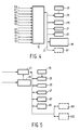
- Vehicle acceleration 113 of Figure 1 may be computed from timed repeated samplings of velocity 57 rather than directly measured. In some cases, this is dictated by the nature of the transducer used to sense the input condition. As one example, reasonably priced present day sensors for determining oxygen content in the exhaust (input line 39) are too slow acting for rapid changes in engine demand situations and therefore that input is not used in Figure 4. These sensors are, however, adequate for long term updating of the system and therefore used in the long term "tuning" of the engine as in Figure 5.
- the inputs 41 may be omitted, while for other inputs, it may be important to sense not only the input value, but also its rate of change.
- one of the n inputs 41 is accelerator pedal position, but for rapid modification of the engine operating parameters, it may be desirable to know not only that the operator has depressed the pedal, but also that it was depressed rapidly (the first derivative of pedal position) as in emergency passing of another vehicle. It may also be desirable to know that the pedal was depressed rapidly initially and then more slowly later on (the second derivative of pedal position with respect to time).
- the particular inputs used represent a trade off between ideal vehicle management and available memory space along with other economic considerations.
- Figure 4 shows the sources of corrective measures to be placed in the delta random access memory 101 to modify the fuel, ignition and valve control information found in the steady state read only memory 103 and then stored in the operating random access memory 107.
- the instructions in the read only memory 115 are for a given RPM, and effective torque produced by the engine when operating at a given engine coolant temperature; inlet air temperature, barometric pressure and relative humidity; and other engine operating traits or conditions. When these conditions change, the information read from read only memory 115 is modified accordingly and stored in delta random access memory 101 and then transferred to the current operating information random access memory 107 and used for engine control. Such modifications are generally speaking to account for changes in the environment of the vehicle.
- An indication of the indicated mean effective pressure and RPM 61 are used to control the required fuel and the derived ignition time.
- One approach is to measure air mass flow 45 directly, or to measure the barometric pressure 49, temperature 47 and intake manifold pressure 53 and then compute the indicated mean effective pressure (without combustion). In either case, corrections should be made taking the relative humidity 51 into consideration.
- the fuel temperature 55 and fuel octane 69 should be considered.
- Another approach is to measure engine shaft torque 73, and a still further approach is to set the air to fuel ratio based on the use of an oxygen sensor measuring the oxygen content 39 of the exhaust.
- FIG. 2 illustrates a number of alternative vehicle traits and other input information which may be used in the control of the engine.
- the cylinder peak pressure 43, the time 77 at which that peak pressure occurs, and the burn time 79 may all be measured using a cylinder pressure sensor.
- the actual input may be from pressure sensors in one or more of the cylinders which are periodically sampled and the information computed therefrom.
- This same principle may be applied to other inputs such as the accelerator pedal position and its several derivatives discussed above.
- An ionization (flame conduction) sensor in a cylinder can also provide a measure of burn time 79, however, this measure is sometimes difficult to obtain under all engine operating conditions.
- Engine torque 73 can also be measured directly, however, this and cylinder pressure sensors are, at the present time, relatively expensive.
- Exhaust oxygen sensors 39 are commercially available and work relatively well, but they must be up to near steady state operating temperature before valid results are obtained. They have a slow time response and are also subject to ageing causing inaccurate indications.
- Exhaust gas temperature is quite useful as an indication of engine operating efficiency, but these and some of the other sensors possess relatively long time constants and are most useful in long term adjustment of the operating characteristics of the engine. To avoid these long time constant problems, the present system operates the engine based on the information in the steady state ROM 103 as updated (see Figure 5) or calibrated in the calibration RAM 87. Immediate or short term changes in the engine operational requirements are effected primarily by the portion of the system depicted in Figure 4.
- the delta ROM 115 of Figure 4 is a factory set map of appropriate responses to operator indicated changes such as depression of the accelerator or brake pedal for given current operating conditions. It may, of course, be a portion of the general ROM 29 of Figure 2. This map or table is transferred to and updated in delta RAM 101 which may be a portion of the general RAM 27 of Figure 2 which provides the current operating information.
- the circuit of Figure 4 is controlled by RPM and perhaps other measures supplied by the steady state circuit of Figure 3 and stored in command RAM 99 and the other inputs illustrated in Figure 4.
- the several derivatives of pedal positions may be measured by periodic sampling of the inputs on lines 41 and 67.
- test and set-up port 31 is shown in Figures 2 and 3. This port allows data and command access to the main bus 23 so that operational tests may be performed and data can be entered into the EPROM 81 and in particular, the CAL EPROM 83 of Figure 5.
- the calibration computer of Figure 5 obtains sensor data such as shown in Figure 2 and, in the preferred realization, the data shown in Figures 3 and 4.
- the other data line 85 may include a variety of overall performance measures such as exhaust oxygen 39, exhaust gas temperature 59, knock sensing 89, flame rate, combustion chamber ionization measures, peak pressure time 77, or burn time 79. These measurements typically have long time constants or variations which require averaging either of which entails delay and causes difficulties in direct real time utilization of the measurements to control an engine.
- One problem has been that the desired vehicle dynamic responses are fast while the time responses of these sensors are slow and surging or oscillation has been very difficult to control.
- the approach of the present invention utilizes the calibration computer of Figure 5 to classify various dynamic states, measure the mean responses of the delta and steady state controls, and to determine from over all performance data in EPROM 83 what recalibrations are necessary. These recalibrations are created slowly, stored in calibration RAM 87 and periodically transferred to the steady state operating RAM 107 to modify the control of the engine. Thus, the system slowly converges to an individual engine's optimum ignition timing, air to fuel ratio, and valve timing. In the main, however, valve control mapping will be relatively stationary in its profile depending on engine RPM and torque for a given engine. Aircraft applications, for example, might employ a different map to accommodate engine temperature excursions and altitude variations along with different performance demands during take-off, climb and cruise. Such engine operation optimization in response to a set of requirements in conjunction with other conditions can be used to optimize operation of an engine for a variety of applications such as trucking, boating and other mobile or fixed engine environments.
- the approximately correct amount of fuel can be determined and added to the intake air of an automobile engine to generally get satisfactory drivability when the vehicle is under heavy acceleration, is operated under general driving conditions, or is operated in cruise conditions.
- the main problem is to get very good vehicle drivability or engine operation under all of the static and dynamic operating conditions and yet maximize economy and minimize emissions.
- the main root of the problem is in the long time constants in sensing the intake air mass flow rate so that the fuel can be properly adjusted.
- an unthrottled variable valve engine can be used and the air consumed can be more rapidly and accurately determined.
- Rapid valve operation will give rise to reduced pumping losses, increased volumetric efficiency, and allow for controlling the expansion ratio of the engine power stroke.
- the engine instead of controlling the engine by throttling the intake manifold thereby operating the engine in a vacuum pump or variable intake density mode, the engine, and in particular the cylinder charge, may be controlled by governing the duration of time the intake valve is open followed by an adiabatic expansion and compression, or by controlling the net time during the cycle that the intake valve is open as opposed to throttling the intake to the engine.
- Opening the intake valve at a controlled time (dependent on patterns of vehicle performance and other indicators) such as in the order of 10 to 70 degrees after top dead center and closing at the appropriate time increases volumetric efficiency and prevents mixing of exhaust and intake gases which mixing is characteristic of conventionally valved engines during the traditional valve overlap periods.
- Closing the intake valve at a precise point in the cycle will increase low engine speed torque by stopping the reverse flow of the intake mixture back into the intake manifold which occurs in conventionally valved engines at low RPM. Elimination of this exchange of gasses will have a highly desirable impact on operation of the engine such as allowing low speed operation of the engine with higher volumetric efficiency as well as greatly improving the starting and low temperature engine operation.
- the controlled sudden opening of the intake valve is advantageous in increasing and controlling turbulence and improving the mixing of fuel and air during the charging cycle. At low engine speeds, more turbulence is needed for fast burns whereas at higher engine RPM higher turbulence would only serve to increase heat losses, hence, the turbulence support should be varied.
- This turbulence concept is also applicable to Diesel engines especially during low speed, high torque operation where lack of proper burning creates smoke and particulate pollution.
- High turbulence under these conditions greatly improves engine performance. More rapid opening of the exhaust valve will reduce the heretofore necessary lead time in starting exhaust blow down in the expansion stroke. The later opening of the exhaust valve extends the power stroke, reduces carbon monoxide and hydrocarbon emissions due to lessened quenching, and reduces pumping losses as well as lowering exhaust gas temperature. The rapid opening of the exhaust valve near bottom dead center also creates mass flow effects which yield recovered energy in the crank shaft by a subatmospheric exhaust gas venting stroke. Exhaust gas driven superchargers are known, but are ineffective at lower engine speeds.
- Such an exhaust gas driven supercharger may be used in conjunction with the present invention to provide low speed, high torque operation.
- a rapid opening and/or an early opening of the exhaust valve significantly enhances supercharger response at low speed operation.
- the exhaust valve may be opened earlier at any engine speed to shorten the time required for intake air pressure boost from the exhaust gas operated supercharger.
- rapid attack, low speed manifold boost along with late opening of the intake valve is used, cylinder turbulence can be increased to enhance clean burning under high fuel injection levels.
- the more rapid opening of the exhaust valve in the internal combustion engine, with less throttling and the reduction of the peak velocity of the boundary layer of the hot gasses past the valve will reduce heat transfer from the exhaust gases to the valve allowing the valve to run cooler, improving valve life particularly under highly oxidizing lean burn, high power and high temperature conditions.
- an exhaust gas driven supercharger more exhaust gas energy can be recovered to increase supercharger output.
- the reduced exhaust gas quenching will reduce unburned hydrocarbon and carbon monoxide concentration in the exhaust.
- the exhaust gases that are normally emitted near the end of the exhaust stroke are rich in unburned hydrocarbons due to scavenging effects of the unburned boundary layers close to the cooler combustion chamber walls and the boiling of unburned hydrocarbons out of cavities such as around the head gasket and around the piston and its compression rings that were deposited there due to pressurization of the charge due to the compression stroke and burning charge pressurization. Rapid closing of the exhaust valve will retain more of these emission rich gases for reburning and the control of exhaust valve opening that controls the expansion ratio of the engine will go toward greatly reducing or eliminating the need for the catalytic converter.
- the use of controlled exhaust gas retention can also eliminate the present exhaust gas recirculating devices.
- Precise differential electronic control of the opening and closings times of the valves allows a control of the mass flow through the intake and exhaust valves in various operating modes with a resulting reduction of undesirable emissions, increase in volumetric efficiency and generally allows an optimization of engine performance.
- Differential control of ignition and fuel can allow all cylinders to be essentially identical thereby allowing a closer approach to the lean burn limit or to other critical points.
- Such precise electronic control can facilitate a number of further modifications including the fact that all cylinders may be purged with fresh air during shut down and that all valves may be closed when the engine is not in use, thereby eliminating exposure to the atmosphere and reducing corrosion within the combustion chambers due to residual gasses, condensates and oxides of nitrogen.
- Initial cranking to start the engine may be performed with appropriate valves maintained open until cranking speed is sufficiently high. This provides a "compressionless" cranking to aid cold weather starting. Cold engine starting and running during the warm-up period without consuming excessive fuel is made possible by 6-cycle operation where one additional compression and expansion are used to vaporize the fuel. This approach will greatly assist in the use of low volatility (low Reed vapor pressure) fuels that are safer and provide less evaporation to the atmosphere. This 6-cycle mode of operation is described in greater detail in the abovementioned Serial No. 153,257 PNEUMATIC ELECTRONIC VALVE ACTUATOR application.
- Control of the number of cylinders in use, as during steady state cruse on a highway, or other low demand condition allows the active cylinders to be operated more efficiently because of the superior entropy due to higher burn pressures and temperatures that are required to get the demanded power level. Leaner burns can be used on the remaining cylinders due to the higher pressures and temperatures allowing higher ignitability and higher propensity of burning of the charge.
- Engines equipped with the present electronically controllable valve arrangement may be used to aid normal or rapid deceleration by closing selected valves for operation using fewer than the full complement of cylinders or no powered cylinders allowing for vehicle slow down due to the rolling friction and aerodynamic losses under conditions where engine output is selectively less that the frictional losses, or cause the engine to absorb power in an air compressor mode.
- heat recovery When spark, fuel and valving are controlled, heat recovery by controlling air intake temperature is facilitated. For example, high heat recovery may be used when the combustion temperature is low as when operating the engine well below maximum torque. Such heat recovery may also help control combustibility under lean or high exhaust gas retention conditions. Ideally, the combustion temperature would be held to a predetermined maximum where one would have the best entropy position but yet controlled NOX production.
- Reduced hydrocarbon emission results from higher expansion ratio, less quenching at the exhaust valve, reduced exhaust gas blow-down time, lower emission at the end of the exhaust stroke as well as during deceleration, and generally less valve overlap operation as well as lean burn and programming the engine to use fewer than the full complement of cylinders when possible. These combine to greatly reduce the need for catalytic converters. General improvement in efficiency may be achieved by increased and controllable expansion of the power stroke gases resulting, in part, from the very rapid opening of the present valve arrangement.
- the conventional exhaust valve may begin to open at 45 to 80 degrees before bottom dead center (for a 0.01 inch seat clearance) and at 60 or more psi gas pressure in order to achieve the momentum of the gas mass necessary to evacuate the exhaust gases against a great deal of exhaust gas valve port throttling.
- the valve of the present invention may be opened at near bottom dead center to utilize more of the expansion during the power stroke.
- the conventional engine exhaust valve may close 45 degrees after top dead center with the corresponding intake valve opening 20 to 40 degrees before top dead center resulting in perhaps 70 degrees of overlap where charge diluting exhaust is pulled into the intake manifold and then back into the cylinder resulting in charge heterogeneity and hence lean burn ignitability and burning problems. With the present invention, there is, in general, no such overlap between the intake and exhaust valves and hence there are less problems with developing heterogeneous charges and extending the lean burn limit.
- the full control of the opening and closing of the valves of a reciprocating engine allows for a design that has a basic controllable high expansion ratio under normal operation and can effectively change that expansion ratio to allow for the same cylinder charge mass when the temperature of the charge varies.
- an engine of longer stroke for the same bore and end combustion chamber volume may be utilized, and/or complementary supercharging may be used. This makes it possible to recover heat from the exhaust making trade offs of higher efficiency due to lower entropy of the higher burn temperatures against the production of NOX due to these higher temperatures and the increased efficiency derived from higher expansion ratios.
- a fast burn, long stroke, high speed engine with reduced maximum temperatures and dwell time at those temperatures reduces NOX emission.
- Opening of the exhaust valve should usually occur when the pressure in the cylinder is nearly the same as the pressure in the exhaust port (generally atmospheric or crankcase pressure) Exhaust valve opening at other times reduces engine efficiency and increases undesirable emissions by purging unburned hydrocarbons from the cylinder. This near zero pressure differential exhaust valve opening time depends upon the current engine status.
- Valve operation in mode 1 as depicted in Figure 11 of that copending application may be used at comparatively low speeds when the duration of valve operation (the time the valve remains open or closed) is sufficiently long compared to the time required to actuate or move the valve from one position to the other At higher engine RPM, the engine may be switched over to mode 2. It will be noted that, in mode 1, the portion of the cycle during which the intake valve is open increases as engine speed increases while in mode 2, the portion of the cycle during which the intake valve is open decreases with increasing engine speed.
- mode 2 has a highly desirable feature of treating the fuel to a more turbulent experience and, hence, is superior to mode 1 in evaporating and homogenizing the fuel in the air/fuel charge for cold starting.
- Cranking of the engine may also take place with the exhaust valve kept open and the intake valve kept closed (or with the exhaust valve kept closed and the intake valve kept open) to take advantage of engine momentum to help engine starting when the valves are suddenly properly sequenced.
- Such delayed valve operation starting may be in either mode 1 or mode 2 and may use delayed input valve opening to develop high velocity and turbulent air/fuel mixture flow with its associated improved evaporation and mixing of the air/fuel charge.
- the versatile control of the present invention allows further modes of operation including opening and closing the intake valve in synchronism with engine speed to operate the engine as a conventional throttled engine, or temporary operation as a two stroke cycle engine.
- Such a two stroke cycle mode of operation is known as "harmonic induction" with the exhaust valve opening slightly prior to bottom dead center and remaining open until slightly after bottom dead center whereupon the exhaust valve closes and the intake valve opens for a short period followed by closing of the intake valve and compression for the remainder of the cycle.
- the control also provides for a method of starting and accelerating a vehicle through a range of vehicle speeds during which the vehicle internal combustion engine is operated selectively in a plurality of different operating modes.
- cranking of the engine may be accomplished in a compressionless mode preparatory to starting the engine, the engine may be run in a second mode at a relatively low speed for a warn-up interval as a six-stroke cycle engine where each engine cylinder cycle includes an essentially adiabatic compression and expansion.
- the higher volumetric efficiency with the valving opening and closing at top and bottom dead center along with the additional strokes allows cold starting with reduced vapor pressure fuels.
- the computer may effect a conversion to a third mode of operation as a four-stroke cycle engine during normal engine operation.
- This third mode may include modes 1 and 2 of the above described copending application.
- Increasing the engine speed and converting to operation in a fourth mode as a two-stroke cycle engine, or operation as a conventional throttled engine under high demand conditions is also possible.
- the six-stroke cycle mode of operation has extra compression and expansion strokes after the intake and compression of a four-cycle mode.
- the purpose of this extra revolution of the crankshaft is to evaporate and more thoroughly mix the fuel and air so that cold start and run can take place without the presently used automatic choke or special extensive fuel enrichment. This leads to better cold starting and cold running without causing the extensive unburned hydrocarbon emissions of the present day engines which now occur prior to the time the catalytic converter comes up to temperature.
- conversion may be made to any of several four-stroke cycle modes.
- the intake valve may be opened at a preferred time and the closing time controlled to thereby control the quantity of the ingested charge. This closing may take place prior to or slightly after bottom dead center (mode 1) or well after bottom dead center but prior to top dead center (mode 2).
- Controlling the closing time of the exhaust valves may also be used to control the fuel/air mixture either separately or in conjunction with controlled intake valve opening and closing as in the previous examples. If the exhaust valve closes prior to top dead center, retained exhaust gas will be placed in an adiabatic compression and subsequent adiabatic expansion prior to the time the intake valve opens. The time at which the exhaust valve closes controls the volume of retained exhaust gas and therefore also controls the volume if ingested fuel and air when the intake valve opens as well as the retained heat in the cylinder. The capability to control retained heat can aid in lean burning. Lean burns burn slowly and to get the most useful burn at a given RPM the ignition should take place at an early time during the compression stroke. Successful ignition depends on the air/fuel mix and the density and temperature of the ignition plasma.
- Retained exhaust gas gives a higher temperature and pressure for a given ignition time in the cycle with a higher probability of ignition and flame propagation through the surrounding gas. This can within certain limits greatly extend the lean burn limits and can be used to reduce emissions. Due to the earlier ignition and higher temperature of the cylinder gas before ignition, more thorough burning can take place which will reduce unburned hydrocarbon and carbon monoxide emissions. The lower energy yield of the cylinder gas reduces the maximum burn temperature which in turn reduces NOX emissions.
- mode 2 Another advantage of operating intake valves in mode 2 as compared to mode 1 is that finer control over the ingested charge is expected at all engine speeds.
- the minimum charge is controlled by the time to open plus the time to close the intake valve. When the engine is operating at a higher speed, this minimum time consumes greater crankshaft angular rotation and the minimum charge may not be as low as desired.
- the minimum charge is not controlled by the sum of these opening and closing times in mode 2 and mode 2 allows for a full range of control over all engine speeds.
- an internal combustion engine to control the turbulence of the gasses within at least one cylinder of the engine is possible by varying the time in the engine cycle at which an intake valve of the controlled cylinder is opened and, in particular, opening the intake valve earlier in the cycle at higher engine speeds and later in the cycle at lower engine speeds.
- the system can minimize particle emissions in the engine exhaust.
- valves of individual cylinders of an internal combustion engine over a range of engine speeds to optimize engine efficiency is possible by opening the exhaust valve of each cylinder during the cylinder's expansion stroke at a time when the pressure in the cylinder is near the pressure in its exhaust port.
- the valve is opened earlier in the stroke when the demand on the engine is low and later in the stroke when the demand on the engine is higher.
- the valves of individual cylinders of an internal combustion engine may be operated over a range of engine speeds to optimize engine efficiency by ensuring that the intake and exhaust valves of a common cylinder are not open at the same time while the engine is operating at lower speeds and opening the intake valve of each cylinder while the corresponding exhaust valve of that cylinder is still open at higher engine speeds. Higher and lower speeds as well as earlier and later in the stroke are relative terms with particular thresholds being design considerations for particular engines.
- each intake valve is opened when the piston of its cylinder is near top dead center and closed when that piston is near bottom dead center.
- Control over one or more of the cylinders of a multiple piston internal combustion engine is accomplished by storing a plurality of different cylinder operation time determining values, monitoring a plurality of current engine operating traits including traits indigenous to individual ones of the engine cylinders, selecting the value for a particular cylinder best suited to the current operating traits, and controlling said particular cylinder at the time determined by the selected value.
- the time of ignition, fuel supply, and intake and exhaust valve opening and closing times for each cylinder may be controlled to optimize performance while minimizing undesirable exhaust emissions.
- At least one of the vehicle internal combustion engine cylinders may be operated in a plurality of different operating modes to decelerate a vehicle through a range of vehicle speeds by removing fuel supply to the cylinder for modest deceleration, maintaining the cylinder valves closed to operate the cylinder in an adiabatic mode for medium deceleration, and opening and closing the cylinder valves to operate the cylinder in a nonadiabatic energy absorbing compressor mode for high deceleration.
- Enhanced low engine speed operation of an exhaust gas actuated supercharger equipped engine may be achieved by opening the exhaust valves of the engine when the associated cylinder pressure is significantly above exhaust port pressure thereby releasing higher pressure exhaust gas to drive the supercharger.
Applications Claiming Priority (2)
| Application Number | Priority Date | Filing Date | Title |
|---|---|---|---|
| US226418 | 1988-07-29 | ||
| US07/226,418 US4945870A (en) | 1988-07-29 | 1988-07-29 | Vehicle management computer |
Publications (3)
| Publication Number | Publication Date |
|---|---|
| EP0352861A2 true EP0352861A2 (fr) | 1990-01-31 |
| EP0352861A3 EP0352861A3 (en) | 1990-08-08 |
| EP0352861B1 EP0352861B1 (fr) | 1993-02-10 |
Family
ID=22848827
Family Applications (1)
| Application Number | Title | Priority Date | Filing Date |
|---|---|---|---|
| EP89201942A Expired - Lifetime EP0352861B1 (fr) | 1988-07-29 | 1989-07-24 | Calculateur de gestion d'automobile |
Country Status (4)
| Country | Link |
|---|---|
| US (1) | US4945870A (fr) |
| EP (1) | EP0352861B1 (fr) |
| JP (1) | JP2984688B2 (fr) |
| DE (1) | DE68904834T2 (fr) |
Cited By (12)
| Publication number | Priority date | Publication date | Assignee | Title |
|---|---|---|---|---|
| DE4136911A1 (de) * | 1991-11-09 | 1993-05-13 | Till Keesmann | Verfahren zur katalytischen nachverbrennung der abgase einer mit mehreren zylindern ausgestatteten brennkraftmaschine und vorrichtung zur ausuebung dieses verfahrens |
| WO1999009313A1 (fr) * | 1997-08-20 | 1999-02-25 | Daimlerchrysler Ab | Procede pour le demarrage d'un moteur a combustion interne |
| EP0669016B1 (fr) * | 1992-11-16 | 2000-02-02 | Harris Corporation | Procede de reduction autonome de la consommation de puissance dans un systeme informatique |
| GB2367859A (en) * | 2000-10-12 | 2002-04-17 | Lotus Car | Methods of operating i.c. engines having electrically controlled actuators for the inlet and/or exhaust valves |
| EP1136678A3 (fr) * | 2000-03-23 | 2002-08-28 | Nissan Motor Co., Ltd. | Système de réglage pour un moteur à combustion interne avec commande des soupapes variable |
| US6659082B1 (en) | 1998-02-07 | 2003-12-09 | Daimlerchrysler Ag | Method for operating a four-stroke internal combustion engine |
| EP1017931B1 (fr) * | 1997-11-14 | 2003-12-10 | Robert Bosch Gmbh | capteur pour la determination de l'air aspire par un moteur a combustion interne |
| EP1447548A1 (fr) * | 2003-02-17 | 2004-08-18 | Ford Global Technologies, Inc. | Procédé et système de commande de couple dans un véhicule |
| DE10354428A1 (de) * | 2003-11-21 | 2005-06-23 | Bayerische Motoren Werke Ag | Verfahren zum Betrieb einer Brennkraftmaschine |
| US6910449B2 (en) | 2002-12-30 | 2005-06-28 | Ford Global Technologies, Llc | Method for auto-ignition operation and computer readable storage device for use with an internal combustion engine |
| WO2008016426A2 (fr) * | 2006-07-28 | 2008-02-07 | Caterpillar Inc. | Gestion d'une source d'énergie thermique et système de réduction des émissions |
| FR2936021A1 (fr) * | 2008-09-18 | 2010-03-19 | Inst Francais Du Petrole | Procede de controle de l'admission et de l'echappement d'un moteur a combustion interne du type a fonctionnement degrade d'au moins un cylindre et moteur utilisant un tel procede |
Families Citing this family (80)
| Publication number | Priority date | Publication date | Assignee | Title |
|---|---|---|---|---|
| JP2784928B2 (ja) * | 1988-11-18 | 1998-08-13 | マツダ株式会社 | エンジンの制御装置 |
| JPH0658094B2 (ja) * | 1989-10-31 | 1994-08-03 | いすゞ自動車株式会社 | アルコールエンジンの再燃焼制御装置 |
| US5131354A (en) * | 1989-11-09 | 1992-07-21 | North American Philips Corporation | Method of operating a two-stroke-cycle engine with variable valve timing in a four-stroke-cycle mode |
| JPH03164537A (ja) * | 1989-11-21 | 1991-07-16 | Mitsubishi Electric Corp | 内燃機関のバルブタイミング制御装置 |
| DE3940752A1 (de) * | 1989-12-09 | 1991-06-13 | Bosch Gmbh Robert | Verfahren zum steuern eines ottomotors ohne drosselklappe |
| US5117790A (en) * | 1991-02-19 | 1992-06-02 | Caterpillar Inc. | Engine operation using fully flexible valve and injection events |
| US5205152A (en) * | 1991-02-19 | 1993-04-27 | Caterpillar Inc. | Engine operation and testing using fully flexible valve and injection events |
| JP2656181B2 (ja) * | 1991-10-12 | 1997-09-24 | 本田技研工業株式会社 | 二元燃料エンジン |
| DE4141481C2 (de) * | 1991-12-16 | 2002-04-11 | Oskar Schatz | Verfahren zur Regelung des Luft-Kraftstoff-Verhältnisses eines Verbrennungsmotors, insbesondere eines Verbrennungsmotors der Kolbenbauart |
| US5190013A (en) * | 1992-01-10 | 1993-03-02 | Siemens Automotive L.P. | Engine intake valve selective deactivation system and method |
| JP2697458B2 (ja) * | 1992-02-28 | 1998-01-14 | 三菱自動車工業株式会社 | エンジンの点火時期制御装置 |
| DE4208002B4 (de) * | 1992-03-13 | 2004-04-08 | Robert Bosch Gmbh | System zur Steuerung einer Brennkraftmaschine |
| US5996560A (en) * | 1992-03-23 | 1999-12-07 | Ford Motor Company | Unthrottled engine operation with a heated air cycle |
| US5201296A (en) * | 1992-03-30 | 1993-04-13 | Caterpillar Inc. | Control system for an internal combustion engine |
| US5255637A (en) * | 1992-04-30 | 1993-10-26 | Ford Motor Company | Internal combustion engine with adaptive control of compression ratio |
| US5216987A (en) * | 1992-06-01 | 1993-06-08 | Caterpillar Inc. | Method and apparatus for optimizing breathing utilizing unit valve actuation |
| US5251590A (en) * | 1992-06-01 | 1993-10-12 | Caterpillar Inc. | Method and apparatus for starting an engine utilizing unit valve actuation |
| US5255650A (en) * | 1992-06-01 | 1993-10-26 | Caterpillar Inc. | Engine braking utilizing unit valve actuation |
| US5203830A (en) * | 1992-06-01 | 1993-04-20 | Caterpillar Inc. | Method and apparatus to reduce engine combustion noise utilizing unit valve actuation |
| US5245968A (en) * | 1992-08-04 | 1993-09-21 | Ford Motor Company | System to determine cam phase and cylinder identification for a variable cam timing engine |
| US5487002A (en) * | 1992-12-31 | 1996-01-23 | Amerigon, Inc. | Energy management system for vehicles having limited energy storage |
| US5515818A (en) * | 1993-12-15 | 1996-05-14 | Machine Research Corporation Of Chicago | Electromechanical variable valve actuator |
| US5515832A (en) * | 1994-07-05 | 1996-05-14 | Ford Motor Company | Method of controlling internal combustion engine exhaust hydrocarbons |
| US5529549A (en) * | 1994-09-21 | 1996-06-25 | Moyer; David F. | Hybrid internal combustion engine |
| US5718199A (en) * | 1994-10-07 | 1998-02-17 | Diesel Engine Retarders, Inc. | Electronic controls for compression release engine brakes |
| DE19525815B4 (de) * | 1995-07-15 | 2007-05-03 | Robert Bosch Gmbh | Verfahren zur Erfassung des Lastsignals einer Brennkraftmaschine |
| DE19530274B4 (de) * | 1995-08-17 | 2005-09-08 | Fev Motorentechnik Gmbh | Verfahren zur Steuerung einer Kolbenbrennkraftmaschine |
| DE19534876B4 (de) * | 1995-09-20 | 2006-11-09 | Fev Motorentechnik Gmbh | Verfahren zur Ermittlung der Ventilsteuerzeiten für eine maximale Zylinderfüllung an einer Kolbenbrennkraftmaschine |
| DE19545221B4 (de) * | 1995-12-05 | 2005-08-25 | Robert Bosch Gmbh | Verfahren und Vorrichtung zur Steuerung einer Brennkraftmaschine |
| JP3026157U (ja) * | 1995-12-19 | 1996-07-02 | 忠正 青山 | 自動車の動力駆動制御装置 |
| US5699758A (en) * | 1996-02-15 | 1997-12-23 | Caterpillar Inc. | Method and apparatus for multiple cycle internal combustion engine operation |
| US5634447A (en) * | 1996-03-07 | 1997-06-03 | Navistar International Transportation Corp. | Electronic fuel injection augmentation of an engine compression brake |
| US8215292B2 (en) | 1996-07-17 | 2012-07-10 | Bryant Clyde C | Internal combustion engine and working cycle |
| JPH1037787A (ja) * | 1996-07-24 | 1998-02-10 | Fuji Heavy Ind Ltd | 車両用エンジンのアイドル回転数制御装置 |
| US5735245A (en) * | 1996-10-22 | 1998-04-07 | Southwest Research Institute | Method and apparatus for controlling fuel/air mixture in a lean burn engine |
| US5927075A (en) * | 1997-06-06 | 1999-07-27 | Turbodyne Systems, Inc. | Method and apparatus for exhaust gas recirculation control and power augmentation in an internal combustion engine |
| DE19733137A1 (de) * | 1997-07-31 | 1999-02-04 | Fev Motorentech Gmbh & Co Kg | Verfahren zur Steuerung von elektromagnetischen Aktuatoren zur Betätigung von Gaswechselventilen an Kolbenbrennkraftmaschinen |
| US5862790A (en) * | 1997-09-10 | 1999-01-26 | Ford Global Technologies, Inc. | Method of generating turbulence with intra-cycle cooling for spark ignition engines |
| US5878714A (en) * | 1997-09-10 | 1999-03-09 | Ford Global Technologies, Inc. | Turbulence generation with intra-cycle cooling for spark ignition engines |
| US6138649A (en) | 1997-09-22 | 2000-10-31 | Southwest Research Institute | Fast acting exhaust gas recirculation system |
| US6179096B1 (en) | 1997-11-12 | 2001-01-30 | Diesel Engine Retarders, Inc. | Exhaust brake variable bypass circuit |
| WO1999041495A1 (fr) * | 1998-02-17 | 1999-08-19 | Diesel Engine Retarders, Inc. | Dispositif de restriction de l'echappement |
| DE19819122C2 (de) * | 1998-04-29 | 2001-06-28 | Deere & Co | Steuereinrichtung für Verbrennungsmotoren |
| DE19821551C1 (de) * | 1998-05-14 | 2000-02-24 | Daimler Chrysler Ag | Verfahren zum Betrieb einer Brennkraftmaschine |
| US6436005B1 (en) | 1998-06-18 | 2002-08-20 | Cummins, Inc. | System for controlling drivetrain components to achieve fuel efficiency goals |
| US6944532B2 (en) | 1998-06-18 | 2005-09-13 | Cummins, Inc. | System for controlling an internal combustion engine in a fuel efficient manner |
| US6387011B1 (en) | 1998-06-18 | 2002-05-14 | Cummins, Inc. | System for controlling an internal combustion engine in a fuel efficient manner |
| DE19830974B4 (de) * | 1998-07-10 | 2005-11-03 | Fev Motorentechnik Gmbh | Kaltstartverfahren für eine drosselfreie Mehrzylinder-Kolbenbrennkraftmaschine |
| JP2000073800A (ja) * | 1998-08-28 | 2000-03-07 | Hitachi Ltd | 電磁駆動式吸排気バルブを備えたエンジンの制御装置 |
| US6092496A (en) * | 1998-09-04 | 2000-07-25 | Caterpillar Inc. | Cold starting method for diesel engine with variable valve timing |
| SE521741C2 (sv) * | 1999-06-24 | 2003-12-02 | Volvo Personvagnar Ab | Metod för att styra en flertaktsmotor |
| US6234143B1 (en) | 1999-07-19 | 2001-05-22 | Mack Trucks, Inc. | Engine exhaust brake having a single valve actuation |
| EP1242731A2 (fr) * | 1999-12-18 | 2002-09-25 | Robert Bosch Gmbh | Procede et dispositif pour assurer la commande de l'unite d'entrainement d'un vehicule |
| US6283091B1 (en) | 2000-01-14 | 2001-09-04 | Mack Trucks, Inc. | Method and apparatus for controlling nozzle temperature during engine braking |
| US6739293B2 (en) * | 2000-12-04 | 2004-05-25 | Sturman Industries, Inc. | Hydraulic valve actuation systems and methods |
| JP3661637B2 (ja) * | 2001-12-07 | 2005-06-15 | トヨタ自動車株式会社 | 車両用エンジンおよび変速機の統合制御装置 |
| JP3938736B2 (ja) * | 2002-09-10 | 2007-06-27 | 本田技研工業株式会社 | 内燃機関の燃料噴射装置 |
| JP4066851B2 (ja) * | 2003-03-03 | 2008-03-26 | トヨタ自動車株式会社 | 可変サイクルエンジンおよび運転モードの切り替え方法 |
| JP2004332717A (ja) * | 2003-04-16 | 2004-11-25 | Honda Motor Co Ltd | 2サイクルと4サイクルを切り替え可能な圧縮着火式内燃機関 |
| US6860253B1 (en) * | 2003-08-13 | 2005-03-01 | Caterpillar Inc | Compression release engine brake control using speed error |
| US20050076893A1 (en) * | 2003-10-09 | 2005-04-14 | Jingfeng Guan | Electronic timing system of automobile engine |
| US7559309B2 (en) | 2004-03-19 | 2009-07-14 | Ford Global Technologies, Llc | Method to start electromechanical valves on an internal combustion engine |
| US7194993B2 (en) | 2004-03-19 | 2007-03-27 | Ford Global Technologies, Llc | Starting an engine with valves that may be deactivated |
| US7072758B2 (en) | 2004-03-19 | 2006-07-04 | Ford Global Technologies, Llc | Method of torque control for an engine with valves that may be deactivated |
| US7107947B2 (en) * | 2004-03-19 | 2006-09-19 | Ford Global Technologies, Llc | Multi-stroke cylinder operation in an internal combustion engine |
| US7128043B2 (en) | 2004-03-19 | 2006-10-31 | Ford Global Technologies, Llc | Electromechanically actuated valve control based on a vehicle electrical system |
| US7128687B2 (en) * | 2004-03-19 | 2006-10-31 | Ford Global Technologies, Llc | Electromechanically actuated valve control for an internal combustion engine |
| US7021289B2 (en) | 2004-03-19 | 2006-04-04 | Ford Global Technology, Llc | Reducing engine emissions on an engine with electromechanical valves |
| US7165391B2 (en) | 2004-03-19 | 2007-01-23 | Ford Global Technologies, Llc | Method to reduce engine emissions for an engine capable of multi-stroke operation and having a catalyst |
| US7555896B2 (en) | 2004-03-19 | 2009-07-07 | Ford Global Technologies, Llc | Cylinder deactivation for an internal combustion engine |
| US7383820B2 (en) | 2004-03-19 | 2008-06-10 | Ford Global Technologies, Llc | Electromechanical valve timing during a start |
| US7080613B2 (en) * | 2004-07-12 | 2006-07-25 | General Motors Corporation | Method for auto-ignition combustion control |
| US6966309B1 (en) * | 2004-08-09 | 2005-11-22 | Southwest Research Institute | In-cylinder reburn method for emissions reduction |
| US7418928B2 (en) * | 2006-04-28 | 2008-09-02 | Caterpillar Inc. | Engine and method for operating an engine |
| KR20100096252A (ko) * | 2007-12-21 | 2010-09-01 | 그린 파트너스 테크놀로지 홀딩스 게엠베하 | 피스톤 엔진 시스템 및 방법 |
| JP2010053851A (ja) * | 2008-08-28 | 2010-03-11 | Nobuji Yamamoto | オートサイクルシステムエンジン |
| ITRE20110060A1 (it) * | 2011-08-02 | 2013-02-03 | Emak Spa | "sistema di controllo della carburazione" |
| US9410455B2 (en) * | 2012-12-18 | 2016-08-09 | Jacobs Vehicle Systems, Inc. | Rocker latch for controlling engine valve actuation |
| US9879633B2 (en) * | 2014-12-03 | 2018-01-30 | Ford Global Technologies, Llc | System and method for improving vacuum generation |
| CN109146303A (zh) * | 2018-08-30 | 2019-01-04 | 百度在线网络技术(北京)有限公司 | 车辆运营控制方法、装置及设备 |
Citations (10)
| Publication number | Priority date | Publication date | Assignee | Title |
|---|---|---|---|---|
| US4009695A (en) * | 1972-11-14 | 1977-03-01 | Ule Louis A | Programmed valve system for internal combustion engine |
| JPS5287529A (en) * | 1976-01-14 | 1977-07-21 | Nissan Motor Co Ltd | Apparatus for controlling quantity of fuel feeding cylinders |
| JPS5554633A (en) * | 1978-10-16 | 1980-04-22 | Kawasaki Heavy Ind Ltd | Supercharged diesel engine |
| JPS56146023A (en) * | 1980-04-14 | 1981-11-13 | Toyota Motor Corp | Timing controlling device for fuel injection of diesel engine |
| JPS6088810A (ja) * | 1983-10-20 | 1985-05-18 | Daihatsu Motor Co Ltd | 内燃機関 |
| JPS60233352A (ja) * | 1984-05-07 | 1985-11-20 | Toyota Motor Corp | 独立噴射式内燃機関の燃料噴射量制御装置 |
| JPS6144030A (ja) * | 1984-08-06 | 1986-03-03 | Kubota Ltd | 歩行型作業車の走行用伝動装置 |
| EP0203354A1 (fr) * | 1985-04-25 | 1986-12-03 | Audi Ag | Procédé et circuit de commande d'une soupape |
| US4736724A (en) * | 1986-12-01 | 1988-04-12 | Ford Motor Company | Adaptive lean limit air fuel control using combustion pressure sensor feedback |
| JPH0196430A (ja) * | 1987-10-07 | 1989-04-14 | Honda Motor Co Ltd | 内燃機関の燃料供給方法及び燃料供給装置 |
Family Cites Families (16)
| Publication number | Priority date | Publication date | Assignee | Title |
|---|---|---|---|---|
| FR2500063A1 (fr) * | 1981-02-18 | 1982-08-20 | Aerospatiale | Moteur thermique a quatre temps susceptible de surpuissance temporaire |
| JPS58113555A (ja) * | 1981-12-25 | 1983-07-06 | Nissan Motor Co Ltd | 内燃機関の空燃比制御装置 |
| JPS58152139A (ja) * | 1982-03-04 | 1983-09-09 | Nissan Motor Co Ltd | 内燃機関の制御装置 |
| JPS58214627A (ja) * | 1982-06-07 | 1983-12-13 | Nippon Denso Co Ltd | 燃料噴射ポンプの燃料調量装置 |
| JPS592908U (ja) * | 1982-06-30 | 1984-01-10 | 株式会社小松製作所 | 過給機付エンジン |
| DE3401362C3 (de) * | 1983-02-04 | 1998-03-26 | Fev Motorentech Gmbh | Verfahren zur Steuerung von Viertakt-Kolbenbrennkraftmaschinen |
| DE3307070C2 (de) * | 1983-03-01 | 1985-11-28 | FEV Forschungsgesellschaft für Energietechnik und Verbrennungsmotoren mbH, 5100 Aachen | Stelleinrichtung für ein zwischen zwei Endstellungen verstellbares Schaltelement |
| FR2560645B1 (fr) * | 1984-03-02 | 1988-04-08 | Alsacienne Constr Meca | Procede pour le demarrage et la marche a faible charge d'un moteur diesel et moteur diesel comportant application de ce procede |
| US4593658A (en) * | 1984-05-01 | 1986-06-10 | Moloney Paul J | Valve operating mechanism for internal combustion and like-valved engines |
| JPS6166824A (ja) * | 1984-09-10 | 1986-04-05 | Mazda Motor Corp | エンジンのバルブタイミング制御装置 |
| JPS61119433A (ja) * | 1984-11-16 | 1986-06-06 | Toyota Motor Corp | 自動変速機の変速制御装置 |
| JPS61190131A (ja) * | 1985-02-18 | 1986-08-23 | Mazda Motor Corp | エンジンの制御装置 |
| JPH0663454B2 (ja) * | 1985-03-01 | 1994-08-22 | マツダ株式会社 | エンジンの吸気装置 |
| CA1286557C (fr) * | 1985-05-24 | 1991-07-23 | Christopher Kim Schlunke | Controle des gaz d'echappement de moteurs a deux temps |
| JPH0635847B2 (ja) * | 1986-01-14 | 1994-05-11 | 日産自動車株式会社 | 内燃機関の制御装置 |
| JPS62191636A (ja) * | 1986-02-17 | 1987-08-22 | Nissan Motor Co Ltd | 内燃機関のバルブタイミング制御装置 |
-
1988
- 1988-07-29 US US07/226,418 patent/US4945870A/en not_active Expired - Lifetime
-
1989
- 1989-07-24 DE DE89201942T patent/DE68904834T2/de not_active Expired - Fee Related
- 1989-07-24 EP EP89201942A patent/EP0352861B1/fr not_active Expired - Lifetime
- 1989-07-28 JP JP1194428A patent/JP2984688B2/ja not_active Expired - Fee Related
Patent Citations (10)
| Publication number | Priority date | Publication date | Assignee | Title |
|---|---|---|---|---|
| US4009695A (en) * | 1972-11-14 | 1977-03-01 | Ule Louis A | Programmed valve system for internal combustion engine |
| JPS5287529A (en) * | 1976-01-14 | 1977-07-21 | Nissan Motor Co Ltd | Apparatus for controlling quantity of fuel feeding cylinders |
| JPS5554633A (en) * | 1978-10-16 | 1980-04-22 | Kawasaki Heavy Ind Ltd | Supercharged diesel engine |
| JPS56146023A (en) * | 1980-04-14 | 1981-11-13 | Toyota Motor Corp | Timing controlling device for fuel injection of diesel engine |
| JPS6088810A (ja) * | 1983-10-20 | 1985-05-18 | Daihatsu Motor Co Ltd | 内燃機関 |
| JPS60233352A (ja) * | 1984-05-07 | 1985-11-20 | Toyota Motor Corp | 独立噴射式内燃機関の燃料噴射量制御装置 |
| JPS6144030A (ja) * | 1984-08-06 | 1986-03-03 | Kubota Ltd | 歩行型作業車の走行用伝動装置 |
| EP0203354A1 (fr) * | 1985-04-25 | 1986-12-03 | Audi Ag | Procédé et circuit de commande d'une soupape |
| US4736724A (en) * | 1986-12-01 | 1988-04-12 | Ford Motor Company | Adaptive lean limit air fuel control using combustion pressure sensor feedback |
| JPH0196430A (ja) * | 1987-10-07 | 1989-04-14 | Honda Motor Co Ltd | 内燃機関の燃料供給方法及び燃料供給装置 |
Non-Patent Citations (7)
| Title |
|---|
| PATENT ABSTRACTS OF JAPAN, vol. 1, no. 144 (M-048), 24th November 1977; & JP-A-52 087 529 (NISSAN MOTOR CO., LTD) 21-07-1977 * |
| PATENT ABSTRACTS OF JAPAN, vol. 10, no. 200 (M-498), 12th July 1986; & JP-A-61 044 030 (KUBOTA LTD) 03-03-1986 * |
| PATENT ABSTRACTS OF JAPAN, vol. 10, no. 96 (M-469), 12th April 1982; & JP-A-60 233 352 (TOYOTA JIDOSHA K.K.) 20-11-1985 * |
| PATENT ABSTRACTS OF JAPAN, vol. 13, no. 305 (M-849), 7th October 1987; & JP-A-1 096 430 (HONDA MOTOR CO., LTD) 14-04-1989 * |
| PATENT ABSTRACTS OF JAPAN, vol. 4, no. 96 (M-020), 11th July 1980; & JP-A-55 054 633 (KAWASAKI HEAVY IND. LTD) 22-04-1980 * |
| PATENT ABSTRACTS OF JAPAN, vol. 6, no. 29 (M-113), 20th February 1982; & JP-A-56 146 023 (TOYOTA MOTOR CORP.) 13-11-1981 * |
| PATENT ABSTRACTS OF JAPAN, vol. 9, no. 231 (M-414), 18th September 1985; & JP-A-60 088 810 (DIAHATSU KOGYO K.K.) 18-05-1985 * |
Cited By (17)
| Publication number | Priority date | Publication date | Assignee | Title |
|---|---|---|---|---|
| DE4136911A1 (de) * | 1991-11-09 | 1993-05-13 | Till Keesmann | Verfahren zur katalytischen nachverbrennung der abgase einer mit mehreren zylindern ausgestatteten brennkraftmaschine und vorrichtung zur ausuebung dieses verfahrens |
| EP0669016B1 (fr) * | 1992-11-16 | 2000-02-02 | Harris Corporation | Procede de reduction autonome de la consommation de puissance dans un systeme informatique |
| WO1999009313A1 (fr) * | 1997-08-20 | 1999-02-25 | Daimlerchrysler Ab | Procede pour le demarrage d'un moteur a combustion interne |
| EP1017931B1 (fr) * | 1997-11-14 | 2003-12-10 | Robert Bosch Gmbh | capteur pour la determination de l'air aspire par un moteur a combustion interne |
| US6659082B1 (en) | 1998-02-07 | 2003-12-09 | Daimlerchrysler Ag | Method for operating a four-stroke internal combustion engine |
| EP1136678A3 (fr) * | 2000-03-23 | 2002-08-28 | Nissan Motor Co., Ltd. | Système de réglage pour un moteur à combustion interne avec commande des soupapes variable |
| US6523504B2 (en) | 2000-03-23 | 2003-02-25 | Nissan Motor Co., Ltd. | Control system for controlling variable valve type internal combustion engine |
| GB2367859A (en) * | 2000-10-12 | 2002-04-17 | Lotus Car | Methods of operating i.c. engines having electrically controlled actuators for the inlet and/or exhaust valves |
| US7400966B2 (en) | 2002-12-30 | 2008-07-15 | Ford Global Technologies, Llc | Method for auto-ignition operation and computer readable storage device for use with an internal combustion engine |
| US7793637B2 (en) | 2002-12-30 | 2010-09-14 | Ford Global Technologies, Llc | Method for auto-ignition operation and computer readable storage device for use with an internal combustion engine |
| US6910449B2 (en) | 2002-12-30 | 2005-06-28 | Ford Global Technologies, Llc | Method for auto-ignition operation and computer readable storage device for use with an internal combustion engine |
| US7441538B2 (en) | 2002-12-30 | 2008-10-28 | Ford Global Technologies, Llc | Method for auto-ignition operation and computer storage device for use with an internal combustion engine |
| EP1447548A1 (fr) * | 2003-02-17 | 2004-08-18 | Ford Global Technologies, Inc. | Procédé et système de commande de couple dans un véhicule |
| DE10354428A1 (de) * | 2003-11-21 | 2005-06-23 | Bayerische Motoren Werke Ag | Verfahren zum Betrieb einer Brennkraftmaschine |
| WO2008016426A3 (fr) * | 2006-07-28 | 2008-03-20 | Caterpillar Inc | Gestion d'une source d'énergie thermique et système de réduction des émissions |
| WO2008016426A2 (fr) * | 2006-07-28 | 2008-02-07 | Caterpillar Inc. | Gestion d'une source d'énergie thermique et système de réduction des émissions |
| FR2936021A1 (fr) * | 2008-09-18 | 2010-03-19 | Inst Francais Du Petrole | Procede de controle de l'admission et de l'echappement d'un moteur a combustion interne du type a fonctionnement degrade d'au moins un cylindre et moteur utilisant un tel procede |
Also Published As
| Publication number | Publication date |
|---|---|
| EP0352861B1 (fr) | 1993-02-10 |
| DE68904834D1 (de) | 1993-03-25 |
| EP0352861A3 (en) | 1990-08-08 |
| JP2984688B2 (ja) | 1999-11-29 |
| US4945870A (en) | 1990-08-07 |
| JPH02104946A (ja) | 1990-04-17 |
| DE68904834T2 (de) | 1994-01-27 |
Similar Documents
| Publication | Publication Date | Title |
|---|---|---|
| US4945870A (en) | Vehicle management computer | |
| US5123397A (en) | Vehicle management computer | |
| US7059296B2 (en) | Method for auto-ignition operation and computer readable storage device | |
| US5081969A (en) | Ignition combustion pre-chamber for internal combustion engines with constant stoichiometric air-fuel mixture at ignition | |
| Ma | Effect of variable engine valve timing on fuel economy | |
| US20100077990A1 (en) | Control of spark ignited internal combustion engine | |
| JPS587816B2 (ja) | 可変圧縮比内燃機関 | |
| GB2226596A (en) | Regulating two-stroke engine intake and exhaust | |
| US7703442B2 (en) | Method for operating an internal combustion engine | |
| US5131354A (en) | Method of operating a two-stroke-cycle engine with variable valve timing in a four-stroke-cycle mode | |
| Simko et al. | Exhaust emission control by the Ford Programmed Combustion process—PROCO | |
| US5083533A (en) | Two-stroke-cycle engine with variable valve timing | |
| JP2003500592A (ja) | 圧縮点火と火花点火を交互に行う4行程往復ピストン内燃機関の運転方法 | |
| CN112912603A (zh) | 用于操作内燃机、特别是燃气发动机的方法 | |
| GB2243664A (en) | Valve timing adjusting device | |
| JP2000510545A (ja) | 希薄な燃料−空気混合気で運転されるガソリン機関の有害な排気ガス放出物の減少方法 | |
| Lenz et al. | Initial Test Results of an Electro-Hydraulic Variable-Valve Actuation System on a Firing Engine | |
| CA1317514C (fr) | Moteur a combustion interne | |
| US5189996A (en) | Two-stroke-cycle engine with variable valve timing | |
| JPH09250435A (ja) | エンジンの制御方法及びその制御装置 | |
| JPH0270917A (ja) | 2サイクルエンジン | |
| Nagesh et al. | Experimental Investigation on Extended Expansion Engine (EEE) | |
| EP1435445A1 (fr) | Moteur à combustion interne, méthode de fonctionnement en auto-allumage et support d'enregistrement lisible par ordinateur | |
| JP2519110B2 (ja) | オット―サイクルエンジン | |
| US3991725A (en) | Internal combustion engine having auxiliary combustion chambers |
Legal Events
| Date | Code | Title | Description |
|---|---|---|---|
| PUAI | Public reference made under article 153(3) epc to a published international application that has entered the european phase |
Free format text: ORIGINAL CODE: 0009012 |
|
| AK | Designated contracting states |
Kind code of ref document: A2 Designated state(s): BE DE ES FR GB IT NL SE |
|
| PUAL | Search report despatched |
Free format text: ORIGINAL CODE: 0009013 |
|
| AK | Designated contracting states |
Kind code of ref document: A3 Designated state(s): BE DE ES FR GB IT NL SE |
|
| 17P | Request for examination filed |
Effective date: 19910206 |
|
| 17Q | First examination report despatched |
Effective date: 19910416 |
|
| GRAA | (expected) grant |
Free format text: ORIGINAL CODE: 0009210 |
|
| AK | Designated contracting states |
Kind code of ref document: B1 Designated state(s): BE DE ES FR GB IT NL SE |
|
| PG25 | Lapsed in a contracting state [announced via postgrant information from national office to epo] |
Ref country code: SE Effective date: 19930210 Ref country code: NL Effective date: 19930210 Ref country code: ES Free format text: THE PATENT HAS BEEN ANNULLED BY A DECISION OF A NATIONAL AUTHORITY Effective date: 19930210 Ref country code: BE Effective date: 19930210 |
|
| REF | Corresponds to: |
Ref document number: 68904834 Country of ref document: DE Date of ref document: 19930325 |
|
| ITF | It: translation for a ep patent filed |
Owner name: ING. C. GREGORJ S.P.A. |
|
| ITPR | It: changes in ownership of a european patent |
Owner name: CAMBIO RAGIONE SOCIALE;MAGNAVOX ELECTRONIC SYSTEMS |
|
| ET | Fr: translation filed | ||
| NLV1 | Nl: lapsed or annulled due to failure to fulfill the requirements of art. 29p and 29m of the patents act | ||
| REG | Reference to a national code |
Ref country code: FR Ref legal event code: CD |
|
| PLBE | No opposition filed within time limit |
Free format text: ORIGINAL CODE: 0009261 |
|
| STAA | Information on the status of an ep patent application or granted ep patent |
Free format text: STATUS: NO OPPOSITION FILED WITHIN TIME LIMIT |
|
| 26N | No opposition filed | ||
| REG | Reference to a national code |
Ref country code: FR Ref legal event code: TP Ref country code: FR Ref legal event code: CD |
|
| REG | Reference to a national code |
Ref country code: GB Ref legal event code: 732E |
|
| REG | Reference to a national code |
Ref country code: FR Ref legal event code: TP |
|
| REG | Reference to a national code |
Ref country code: GB Ref legal event code: 732E |
|
| REG | Reference to a national code |
Ref country code: GB Ref legal event code: IF02 |
|
| PGFP | Annual fee paid to national office [announced via postgrant information from national office to epo] |
Ref country code: DE Payment date: 20020916 Year of fee payment: 14 |
|
| PGFP | Annual fee paid to national office [announced via postgrant information from national office to epo] |
Ref country code: GB Payment date: 20030710 Year of fee payment: 15 |
|
| PGFP | Annual fee paid to national office [announced via postgrant information from national office to epo] |
Ref country code: FR Payment date: 20030725 Year of fee payment: 15 |
|
| PG25 | Lapsed in a contracting state [announced via postgrant information from national office to epo] |
Ref country code: DE Free format text: LAPSE BECAUSE OF NON-PAYMENT OF DUE FEES Effective date: 20040203 |
|
| PG25 | Lapsed in a contracting state [announced via postgrant information from national office to epo] |
Ref country code: GB Free format text: LAPSE BECAUSE OF NON-PAYMENT OF DUE FEES Effective date: 20040724 |
|
| GBPC | Gb: european patent ceased through non-payment of renewal fee |
Effective date: 20040724 |
|
| PG25 | Lapsed in a contracting state [announced via postgrant information from national office to epo] |
Ref country code: FR Free format text: LAPSE BECAUSE OF NON-PAYMENT OF DUE FEES Effective date: 20050331 |
|
| REG | Reference to a national code |
Ref country code: FR Ref legal event code: ST |
|
| PG25 | Lapsed in a contracting state [announced via postgrant information from national office to epo] |
Ref country code: IT Free format text: LAPSE BECAUSE OF NON-PAYMENT OF DUE FEES;WARNING: LAPSES OF ITALIAN PATENTS WITH EFFECTIVE DATE BEFORE 2007 MAY HAVE OCCURRED AT ANY TIME BEFORE 2007. THE CORRECT EFFECTIVE DATE MAY BE DIFFERENT FROM THE ONE RECORDED. Effective date: 20050724 |