EP1016103B1 - Power transformer/inductor - Google Patents
Power transformer/inductor Download PDFInfo
- Publication number
- EP1016103B1 EP1016103B1 EP98902351A EP98902351A EP1016103B1 EP 1016103 B1 EP1016103 B1 EP 1016103B1 EP 98902351 A EP98902351 A EP 98902351A EP 98902351 A EP98902351 A EP 98902351A EP 1016103 B1 EP1016103 B1 EP 1016103B1
- Authority
- EP
- European Patent Office
- Prior art keywords
- power transformer
- inductor according
- inductor
- layers
- winding
- Prior art date
- Legal status (The legal status is an assumption and is not a legal conclusion. Google has not performed a legal analysis and makes no representation as to the accuracy of the status listed.)
- Expired - Lifetime
Links
Images


Classifications
-
- H—ELECTRICITY
- H01—ELECTRIC ELEMENTS
- H01F—MAGNETS; INDUCTANCES; TRANSFORMERS; SELECTION OF MATERIALS FOR THEIR MAGNETIC PROPERTIES
- H01F27/00—Details of transformers or inductances, in general
- H01F27/34—Special means for preventing or reducing unwanted electric or magnetic effects, e.g. no-load losses, reactive currents, harmonics, oscillations, leakage fields
-
- H—ELECTRICITY
- H01—ELECTRIC ELEMENTS
- H01F—MAGNETS; INDUCTANCES; TRANSFORMERS; SELECTION OF MATERIALS FOR THEIR MAGNETIC PROPERTIES
- H01F27/00—Details of transformers or inductances, in general
- H01F27/28—Coils; Windings; Conductive connections
- H01F27/2823—Wires
- H01F27/2828—Construction of conductive connections, of leads
-
- H—ELECTRICITY
- H01—ELECTRIC ELEMENTS
- H01F—MAGNETS; INDUCTANCES; TRANSFORMERS; SELECTION OF MATERIALS FOR THEIR MAGNETIC PROPERTIES
- H01F27/00—Details of transformers or inductances, in general
- H01F27/28—Coils; Windings; Conductive connections
- H01F27/288—Shielding
-
- Y—GENERAL TAGGING OF NEW TECHNOLOGICAL DEVELOPMENTS; GENERAL TAGGING OF CROSS-SECTIONAL TECHNOLOGIES SPANNING OVER SEVERAL SECTIONS OF THE IPC; TECHNICAL SUBJECTS COVERED BY FORMER USPC CROSS-REFERENCE ART COLLECTIONS [XRACs] AND DIGESTS
- Y10—TECHNICAL SUBJECTS COVERED BY FORMER USPC
- Y10S—TECHNICAL SUBJECTS COVERED BY FORMER USPC CROSS-REFERENCE ART COLLECTIONS [XRACs] AND DIGESTS
- Y10S174/00—Electricity: conductors and insulators
- Y10S174/13—High voltage cable, e.g. above 10kv, corona prevention
Definitions
- the present invention relates to a power transformer/inductor.
- Transformers are used for enabling exchange between two or more electric systems normally having different voltage levels.
- Transformers are available for powers from the VA region to the 1000 MVA region.
- the voltage range has a spectrum of up to the highest transmission voltages used today.
- Electromagnetic induction is used for energy transmission between electric systems.
- Inductors are also an essential component in the transmission of electric energy in for example phase compensation and filtering.
- the transformer/inductor related to the present invention belongs to the so-called power transformers/inductors having rated outputs from several hundred kVA to in excess of 1000 MVA and rated voltages of from 3-4 kV to very high transmission voltages.
- the main object of a power transformer is to enable the exchange of electric energy, between two or more electric systems of mostly differing voltages with the same frequency.
- a conventional power transformer/inductor comprises a transformer core, referred to below as core, formed of laminated commonly oriented sheet, normally of silicon iron.
- the core is composed of a number of core legs connected by yokes.
- a number of windings are provided around the core legs normally referred to as primary, secondary and regulating winding. In power transformers these windings are practically always arranged in concentric configuration and distributed along the length of the core leg.
- the above-mentioned windings constitute one or several coils connected in series, the coils of which having a number of turns connected in series.
- the turns of a single coil normally make up a geometric, continuous unit which is physically separated from the remaining coils.
- a conductor is known through US 5 036 165, in which the insulation is provided with an inner and an outer layer of semiconducting pyrolized glassfiber. It is also known to provide conductors in a dynamo-electric machine with such an insulation, as described in US 5 066 881 for instance, where a semiconducting pyrolized glassfiber layer is in contact with the two parallel rods forming the conductor, and the insulation in the stator slots is surrounded by an outer layer of semiconducting pyrolized glassfiber.
- the pyrolized glassfiber material is described as suitable since it retains its resistivity even after the impregnation treatment.
- the insulation system is normally in the form of a solid- or varnish based insulation and the insulation system on the outside is in the form of a solid cellulose insulation, fluid insulation , and possibly also an insulation in the form of gas.
- Windings with insulation and possible bulky parts represent in this way large volumes that will be subjected to high electric field strengths occurring in and around the active electric magnetic parts belonging to transformers.
- a detailed knowledge of the properties of insulation material is required in order to predetermine the dielectric field strengths which arise and to attain a dimensioning such that there is a minimal risk of electrical discharge. It is important to achieve a surrounding environment which does not change or reduce the insulation properties.
- Today's predominant outer insulation system for conventional high voltage power transformers/inductors consists of cellulose material as the solid insulation and transformer oil as the fluid insulation.
- Transformer oil is based on so-called mineral oil.
- a conventional insulation system is relatively complicated to construct and special measures need to be taken during manufacture in order to utilize good insulation properties of the insulation system.
- the system must have a low moisture content and the solid phase in the insulation system needs to be well impregnated with the surrounding oil so that there is minimal risk of gas pockets.
- a special drying process is carried out on the complete core with windings before it is lowered into the tank. After lowering the core and sealing the tank, the tank is emptied of all air by a special vacuum treatment before being filled with oil. This process is relatively time-consuming seen from the entire manufacturing process in addition to the extensive utilization of resources in the workshop.
- the tank surrounding the transformer must be constructed in such a way that it is able to withstand full vacuum since the process requires that all the gas be pumped out to almost absolute vacuum which involves extra material consumption and manufacturing time.
- the power transformer/ inductor comprises at least one winding in most cases arranged around a magnetizable core which may be of different geometries.
- the term "windings" will be referred to below in order to simplify the following specification.
- the windings are composed of a high voltage cable with solid insulation.
- the cables have at least one centrally situated electric conductor.
- the semiconducting outer layer must be directly earthed at or in the vicinity of both ends of the cable so that the electric stress which arises, both during normal operating voltage and during transient progress, will primarily load only the solid insulation of the cable.
- the semi-conducting layer and these direct earthings form together a closed circuit in which a current is induced during operation.
- the resistivity of the layer must be large enough so that resistive losses arising in the layer are negligible.
- a capacitive current is to flow into the layer through both directly earthed ends of the cable. If the resistivity of the layer is too high, the capacitive current will become so limited that the potential in parts of the layer, during a period of alternating stress, may differ to such an extent from earth potential that regions of the power transformer/inductor other than the solid insulation of the windings will be subjected to electric stress.
- the whole outer layer By directly earthing several points of the semiconducting layer, preferably one point per turn of the winding, the whole outer layer will remain at earth potential and the elimination of the above-mentioned problems is ensured if the conductivity of the layer is high enough.
- This one point earthing per turn of the outer screen is performed in such a way that the earth points rest on a generatrix to a winding and that points along the axial length of the winding are electrically directly connected to a conducting earth track which is connected thereafter to the common earth potential.
- the windings may be subjected to such rapid transient overvoltage that parts of the outer semiconducting layer carry such a potential that areas of the power transformer other than the insulation of the cable are subjected to undesirable electric stress.
- a number of non-linear elements e.g. spark gaps, phanotrons, Zener-diodes or varistors are connected in between the outer semiconducting layer and earth per turn of the winding.Also by connecting a capacitor in between the outer semiconducting layer and earth a non-desirable electric stress may be prevented from arising. A capacitor reduces the voltage even at 50 Hz. This earthing principle will be referred to below as "indirect earthing".
- the second semiconducting layer is directly earthed at both ends of each winding and is indirectly earthed at at least one point between both the ends.
- the individually earthed earthing tracks are connected to earth via either,
- the windings are preferably composed of cables having solid, extruded insulation, of a type now used for power distribution, such as XLPE-cables or cables with EPR-insulation.
- Such cables are flexible, which is an important property in this context since the technology for the device according to the invention is based primarily on winding systems in which the winding is formed from cable which is bent during assembly.
- the flexibility of a XLPE-cable normally corresponds to a radius of curvature of approximately 20 cm for a cable 30 mm in diameter, and a radius of curvature of approximately 65 cm for a cable 80 mm in diameter.
- the term "flexible" is used to indicate that the winding is flexible down to a radius of curvature in the order of four times the cable diameter, preferably eight to twelve times the cable diameter.
- Windings in the present invention are constructed to retain their properties even when they are bent and when they are subjected to thermal stress during operation. It is vital that the layers of the cable retain their adhesion to each other in this context.
- the material properties of the layers are decisive here, particularly their elasticity and relative coefficients of thermal expansion.
- the insulating layer consists of cross-linked, low-density polyethylene
- the semiconducting layers consist of polyethylene with soot and metal particles mixed in.
- the insulating layer may consist, for example, of a solid thermoplastic material such as low-density polyethylene (LDPE), high-density polyethylene (HDPE), polypropylene (PP), polybutylene (PB), polymethyl pentene (PMP), cross-linked materials such as cross-linked polyethylene (XLPE), or rubber such as ethylene propylene rubber (EPR) or silicon rubber.
- LDPE low-density polyethylene
- HDPE high-density polyethylene
- PP polypropylene
- PB polybutylene
- PMP polymethyl pentene
- XLPE cross-linked polyethylene
- EPR ethylene propylene rubber
- the inner and outer semiconducting layers may be of the same basic material but with particles of conducting material such as soot or metal powder mixed in.
- the mechanical properties of these materials are affected relatively little by whether soot or metal powder is mixed in or not - at least in the proportions required to achieve the conductivity necessary according to the invention.
- the insulating layer and the semiconducting layers thus have substantially the same coefficients of thermal expansion.
- Ethylene-vinyl-acetate copolymers/nitrile rubber, butyl graft polyethylene, ethylene-butyl-acrylate-copolymers and ethylene-ethyl-acrylate copolymers may also constitute suitable polymers for the semiconducting layers.
- the materials listed above have relatively good elasticity, with an E-modulus of E ⁇ 500 MPa, preferably ⁇ 200 MPa.
- the elasticity is sufficient for any minor differences between the coefficients of thermal expansion for the materials in the layers to be absorbed in the radial direction of the elasticity so that no cracks or other damage appear and so that the layers are not released from each other.
- the material in the layers is elastic, and the adhesion between the layers is at least of the same magnitude as the weakest of the materials.
- the conductivity of the two semiconducting layers is sufficient to substantially equalize the potential along each layer.
- the conductivity of the outer semiconducting layer is sufficiently large to contain the electrical field in the cable, but sufficiently small not to give rise to significant losses due to currents induced in the longitudinal direction of the layer.
- each of the two semiconducting layers essentially constitutes one equipotential surface, and these layers will substantially enclose the electrical field between them.
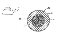
- FIG. 1 shows a cross-sectional view of a high voltage cable 10 which is used traditionally for the transmission of electric energy.
- the shown high voltage cable may for example be a standard XLPE cable 145 kV but without mantle and screen.
- the high voltage cable 10 comprises an electric conductor, which may comprise one or several strands 12 with circular cross-section of for example copper (Cu). These strands 12 are arranged in the center of the high voltage cable 10.
- a first semiconducting layer 14 Around the strands 12 there is arranged a first semiconducting layer 14.
- a first insulating layer 16 for example XLPE insulation.
- Around the first insulating 16 there is arranged a second semiconducting layer 18.
- the high voltage cable 10, shown in Figure 1 is manufactured with a conductor area of between 80 and 3000 mm 2 and with an outer cable diameter of between 20 and 250 mm.
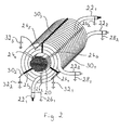
- Figure 2 shows a perspective view of windings with three indirect earthing points per winding turn according to a first embodiment of the present invention.
- Figure 2 shows a core leg designated by the numeral 20 within a power transformer or inductor.
- Two windings 22 1 and 22 2 are arranged around the core leg 20 which are formed from the high-voltage cable (10) shown in Figure 1.
- With the aim of fixing windings 22 1 and 22 2 there are, in this case six radially arranged spacer members 24 1 , 24 2 , 24 3 , 24 4 , 24 5 , 24 6 , per winding turn.
- the outer semiconducting layer is earthed at both ends 26 1 , 26 2 ; 28 1 , 28 2 of each winding 22 1 , 22 2 .
- Spacer members 24 1 , 24 3 , 24 5 which are emphasised in black, are utilised to achieve, in this case, three indirect earthing points per winding turn.
- the spacer member 24 1 is directly connected to a first earthing element 30 1
- spacer member 24 3 is directly connected to a second earthing element 30 2
- spacer member 24 5 is directly connected to a third earthing element 30 3 at the periphery of the winding 22 2 and along the axial length of the winding 22 2 .
- Earthing elements 30 1 , 30 2 , 30 3 may for example be in the form of earthing tracks 30 1 - 30 3 . As shown in Figure 2 the earthing points rest on a generatrix to a winding.
- Each and every one of the earthing elements 30 1 - 30 3 is directly earthed in that they are connected to earth via their own capacitor 32 1 , 32 2 , 32 3 . By earthing indirectly in this way any non-desirable electric stress may be prevented from arising.
- Figure 3 shows a perspective view of windings with one direct earthing point and two indirect earthing points per winding turn according to a second embodiment of the present invention.
- the same parts are designated by the same numerals in order to make the Figures more clear.
- the two windings 22 1 and 22 2 formed from the high-voltage cable 10 shown in Figure 1, are arranged around the core leg 20. Windings 22 1 , 22 2 are fixed by means of six spacer members 24 1 , 24 2 , 24 3 , 24 4 , 24 5 , 24 6 per winding turn.
- the second semiconducting layer (compare with Figure 1) is earthed in accordance with Figure 2.
- Spacer members 24 1 , 24 3 , 24 5 which are marked in black , are used in order to achieve in this case one direct and two indirect earthing points per winding turn.
- spacer member 24 1 is directly connected to a first earthing element 30 1
- spacer member 24 3 is directly connected to a second earthing element 30 2
- spacer member 24 5 is directly connected to a third earthing element 30 3 .
- earthing element 30 1 is directly connected to earth 36, while earthing elements 30 2 , 30 3 are indirectly earthed.
- Earthing element 30 3 is indirectly earthed in that it is connected in series to earth via a capacitor 32.
- Earthing element 30 2 is indirectly earthed in that it is connected in series to earth via a spark gap 34.
- the spark gap is an example of a non-linear element , i.e. an element with a non-linear voltage current characteristic.
- Figure 4 shows a perspective view of windings with one direct earthing point and two indirect earthing points per winding turn according to a third embodiment of the present invention.
- Figures 2 - 4 the same parts are designated by the same numerals in order to make the Figures more clear.
- Figure 4 shows windings 22 1 , 22 2 , a core leg 20, spacer members 24 1 , 24 2 , 24 3 , 24 4 , 24 5 , 24 6 and earthing elements 30 1 , 30 2 , 30 3 arranged in the same way as shown in Figure 3 and will therefore not be described in further detail here.
- Earthing element 30 1 is directly connected to earth, while earthing elements 30 2 , 30 3 are indirectly earthed.
- Earthing elements 30 2 , 30 3 are indirectly earthed in that they are connected in series via their own capacitor.
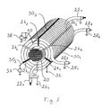
- Figure 5 shows a perspective view of windings with one direct earthing point and two indirect earthing points per winding turn according to a fourth embodiment of the present invention.
- Figures 2 - 5 the same parts are designated the same numerals in order to make the Figures more clear.
- Figure 5 shows windings 22 1 , 22 2 , a core leg 20, spacer members 24 1 , 24 2 , 24 3 , 24 4 , 24 5 , 26 6 , end earthing points 26 1 , 26 2 ; 26 1 , 28 2 and earthing elements 30 1 , 30 2 , 30 3 arranged in the same way as shown in Figures 3 and 4 and will therefore not be described in further detail here.
- Earthing element 30 1 is directly connected to earth 36, while earthing elements 30 2 , 30 3 are indirectly earthed.
- the earthing element 30 2 is indirectly earthed in that it is connected in series to earth via a discharge gap.
- Earthing element 30 3 is indirectly earthed in that it is connected in series to earth via a circuit, comprising a spark gap 38 connected parallel to a capacitor 40.
- the power transformer/inductor in the above shown Figures comprises a magnetizable core. It should however be understood that a power transformer / inductor may be built without a magnetizable core.
Landscapes
- Engineering & Computer Science (AREA)
- Power Engineering (AREA)
- Coils Of Transformers For General Uses (AREA)
- Coils Or Transformers For Communication (AREA)
- General Induction Heating (AREA)
- Housings And Mounting Of Transformers (AREA)
- Discharge Heating (AREA)
Abstract
Description
Claims (12)
- A power transformer/inductor comprising at least one winding composed of a high-voltage cable (10), the cable comprising an electric conductor, a first semiconducting layer (14) arranged around the conductor, an insulating layer (16) arranged around the first semiconducting layer (14) and a second semiconducting layer (18) arranged around the insulating layer (16), whereby the second semiconducting layer (18) is directly earthed at both ends of each winding (221, 222) and at least one point between both the ends is indirectly earthed via either an element (34) with non-linear voltage-current characteristic, an element (34) with non-linear voltage-current characteristic in parallel to a capacitor (32; 321-323), a capacitor (32; 321-323), or a combination of all three alternatives.
- A power transformer/inductor according to claim 1, characterized in that the high-voltage cable (10) is manufactured with a conductor area of between 80 and 3000 mm2 and with an outer cable diameter of between 20 and 250 mm.
- A power transformer/inductor according to any one of claims 1 - 2, characterized in that the direct earthing (36) is performed by means of galvanic connection to earth.
- A power transformer/inductor according to any one of claims 1 - 3, characterized in that the element with non-linear voltage-current characteristic constitutes a spark gap (36), a gas-filled diode, a Zener-diode or a varistor.
- A power transformer/inductor according to any one of claims 1 - 4, characterized in that the power transformer / inductor comprises a magnetizable core.
- A power transformer/inductor according to any one of claims 1 - 4, characterized in that the power transformer / inductor is built without a magnetizable core.
- A power transformer/inductor according to claim 1, characterized in that the winding / windings are flexible (a) and in that said layers adhere to each other.
- A power transformer/inductor according to claim 7, characterized in that said layers are of a material with such an elasticity and with such a relation between the coefficients of thermal expansion of the material that during operation changes in volume, due to temperature variations, are able to be absorbed by the elasticity of the material such that the layers retain their adherence to each other during the temperature variations that appear during operation.
- A power transformer/inductor according to claim 8, characterized in that the materials in the said layers have a high elasticity, preferably with an E-module less than 500 MPa and most preferably less than 200 MPa.
- A power transformer/inductor according to claim 8, characterized in that the coefficients of thermal expansion in the materials of the said layers are substantially equal.
- A power transformer/inductor according to claim 8, characterized in that the adherence between layers is at least of the same rating as in the weakest of the materials.
- A power transformer/inductor according to claim 7, or 8, characterized in that each semiconducting layer constitutes substantially an equipotential surface.
Applications Claiming Priority (5)
| Application Number | Priority Date | Filing Date | Title |
|---|---|---|---|
| SE9700337 | 1997-02-03 | ||
| SE9700337A SE508768C2 (en) | 1997-02-03 | 1997-02-03 | Power transformer-inductor winding |
| SE9704413 | 1997-11-28 | ||
| SE9704413A SE9704413D0 (en) | 1997-02-03 | 1997-11-28 | A power transformer / reactor |
| PCT/SE1998/000154 WO1998034246A1 (en) | 1997-02-03 | 1998-02-02 | Power transformer/inductor |
Publications (2)
| Publication Number | Publication Date |
|---|---|
| EP1016103A1 EP1016103A1 (en) | 2000-07-05 |
| EP1016103B1 true EP1016103B1 (en) | 2003-07-02 |
Family
ID=26662863
Family Applications (1)
| Application Number | Title | Priority Date | Filing Date |
|---|---|---|---|
| EP98902351A Expired - Lifetime EP1016103B1 (en) | 1997-02-03 | 1998-02-02 | Power transformer/inductor |
Country Status (18)
| Country | Link |
|---|---|
| US (1) | US7046492B2 (en) |
| EP (1) | EP1016103B1 (en) |
| JP (1) | JP4372845B2 (en) |
| KR (1) | KR20010049159A (en) |
| CN (1) | CN1193386C (en) |
| AT (1) | ATE244449T1 (en) |
| AU (1) | AU730195B2 (en) |
| BR (1) | BR9807143A (en) |
| CA (1) | CA2276402A1 (en) |
| DE (1) | DE69816101T2 (en) |
| EA (1) | EA001634B1 (en) |
| NO (1) | NO993672L (en) |
| NZ (1) | NZ337095A (en) |
| PL (1) | PL334616A1 (en) |
| SE (1) | SE9704413D0 (en) |
| TR (1) | TR199901580T2 (en) |
| UA (1) | UA54485C2 (en) |
| WO (1) | WO1998034246A1 (en) |
Families Citing this family (38)
| Publication number | Priority date | Publication date | Assignee | Title |
|---|---|---|---|---|
| CZ385898A3 (en) | 1996-05-29 | 1999-05-12 | Abb Ab | Electric High Voltage AC Machine |
| DE69728972T2 (en) | 1996-05-29 | 2005-05-04 | Abb Ab | TRANSFORMER / REACTOR |
| SE9602079D0 (en) | 1996-05-29 | 1996-05-29 | Asea Brown Boveri | Rotating electric machines with magnetic circuit for high voltage and a method for manufacturing the same |
| AU3052997A (en) | 1996-05-29 | 1998-01-05 | Asea Brown Boveri Ab | Rotating electrical machine comprising high-voltage stator winding and elongated support devices supporting the winding and method for manufacturing such machine |
| SE510452C2 (en) | 1997-02-03 | 1999-05-25 | Asea Brown Boveri | Transformer with voltage regulator |
| SE9704413D0 (en) | 1997-02-03 | 1997-11-28 | Asea Brown Boveri | A power transformer / reactor |
| SE9704412D0 (en) | 1997-02-03 | 1997-11-28 | Asea Brown Boveri | A power transformer / reactor |
| SE513083C2 (en) | 1997-09-30 | 2000-07-03 | Abb Ab | Synchronous compensator system and the use of such and phase compensation method in a high voltage field |
| SE513555C2 (en) | 1997-11-27 | 2000-10-02 | Abb Ab | Method of applying a pipe means in a space of a rotating electric machine and rotating electric machine according to the method |
| GB2331858A (en) | 1997-11-28 | 1999-06-02 | Asea Brown Boveri | A wind power plant |
| GB2331853A (en) | 1997-11-28 | 1999-06-02 | Asea Brown Boveri | Transformer |
| SE516002C2 (en) | 2000-03-01 | 2001-11-05 | Abb Ab | Rotary electric machine and method of making a stator winding |
| US6885273B2 (en) | 2000-03-30 | 2005-04-26 | Abb Ab | Induction devices with distributed air gaps |
| SE516442C2 (en) | 2000-04-28 | 2002-01-15 | Abb Ab | Stationary induction machine and cable therefore |
| US6359365B1 (en) * | 2000-08-04 | 2002-03-19 | American Superconductor Corporation | Superconducting synchronous machine field winding protection |
| EP1280259A1 (en) | 2001-07-23 | 2003-01-29 | ALSTOM (Switzerland) Ltd | High-voltage Generator |
| US8350659B2 (en) * | 2009-10-16 | 2013-01-08 | Crane Electronics, Inc. | Transformer with concentric windings and method of manufacture of same |
| US20110090038A1 (en) * | 2009-10-16 | 2011-04-21 | Interpoint Corporation | Transformer having interleaved windings and method of manufacture of same |
| US8901790B2 (en) | 2012-01-03 | 2014-12-02 | General Electric Company | Cooling of stator core flange |
| US10840005B2 (en) | 2013-01-25 | 2020-11-17 | Vishay Dale Electronics, Llc | Low profile high current composite transformer |
| US9640315B2 (en) * | 2013-05-13 | 2017-05-02 | General Electric Company | Low stray-loss transformers and methods of assembling the same |
| US9831768B2 (en) | 2014-07-17 | 2017-11-28 | Crane Electronics, Inc. | Dynamic maneuvering configuration for multiple control modes in a unified servo system |
| CN107004470A (en) | 2014-08-07 | 2017-08-01 | 汉高股份有限及两合公司 | Electroceramic coatings for wires in bundled power transmission cables |
| US9230726B1 (en) | 2015-02-20 | 2016-01-05 | Crane Electronics, Inc. | Transformer-based power converters with 3D printed microchannel heat sink |
| US10998124B2 (en) | 2016-05-06 | 2021-05-04 | Vishay Dale Electronics, Llc | Nested flat wound coils forming windings for transformers and inductors |
| US9780635B1 (en) | 2016-06-10 | 2017-10-03 | Crane Electronics, Inc. | Dynamic sharing average current mode control for active-reset and self-driven synchronous rectification for power converters |
| KR102571361B1 (en) | 2016-08-31 | 2023-08-25 | 비쉐이 데일 일렉트로닉스, 엘엘씨 | Inductor having high current coil with low direct current resistance |
| US9735566B1 (en) | 2016-12-12 | 2017-08-15 | Crane Electronics, Inc. | Proactively operational over-voltage protection circuit |
| US9742183B1 (en) | 2016-12-09 | 2017-08-22 | Crane Electronics, Inc. | Proactively operational over-voltage protection circuit |
| CN108987038B (en) * | 2017-05-31 | 2021-11-26 | 台达电子工业股份有限公司 | Magnetic assembly |
| TWI651910B (en) * | 2017-07-27 | 2019-02-21 | 胡龍江 | Safe high voltage transmission system and equivalent current transmission cable |
| US9979285B1 (en) | 2017-10-17 | 2018-05-22 | Crane Electronics, Inc. | Radiation tolerant, analog latch peak current mode control for power converters |
| US10425080B1 (en) | 2018-11-06 | 2019-09-24 | Crane Electronics, Inc. | Magnetic peak current mode control for radiation tolerant active driven synchronous power converters |
| GB201904528D0 (en) * | 2019-04-01 | 2019-05-15 | Tokamak Energy Ltd | Partial insulation with diagnostic pickup coils |
| US12567533B2 (en) | 2020-03-03 | 2026-03-03 | Vishay Dale Electronics, Llc | Inductor with preformed termination and method and assembly for making the same |
| EP3965126A1 (en) * | 2020-09-03 | 2022-03-09 | SolarEdge Technologies Ltd. | Transformer apparatus |
| USD1034462S1 (en) | 2021-03-01 | 2024-07-09 | Vishay Dale Electronics, Llc | Inductor package |
| US11948724B2 (en) | 2021-06-18 | 2024-04-02 | Vishay Dale Electronics, Llc | Method for making a multi-thickness electro-magnetic device |
Family Cites Families (684)
| Publication number | Priority date | Publication date | Assignee | Title |
|---|---|---|---|---|
| US1304451A (en) | 1919-05-20 | Locke h | ||
| DE386561C (en) | 1923-12-13 | Bergmann Elek Citaets Werke Ak | Machine for the conversion or for the simultaneous generation of alternating currents of different frequencies | |
| DE523047C (en) | 1931-04-18 | Brown Boveir & Cie Ag | Process for the production of slot wedges with iron sheets layered transversely to the longitudinal direction of the wedge for electrical machines | |
| DE406371C (en) | 1924-11-21 | Bergmann Elek Citaets Werke Ak | Machine for the conversion or for the simultaneous generation of alternating currents of different frequencies with fields of different number of poles, which are expediently combined on an inductor, and induced windings assigned to these fields, possibly combined into a common winding | |
| DE336418C (en) | 1921-05-02 | Stanislaus Berger | Support for electrical lines to be led on walls | |
| DE572030C (en) | 1933-03-09 | Bbc Brown Boveri & Cie | Cooling device for the winding heads of high-voltage machines | |
| DE568508C (en) | 1933-01-20 | Bbc Brown Boveri & Cie | AC high-voltage generator with at least two electrically separate windings | |
| DE425551C (en) | 1926-02-20 | Bbc Brown Boveri & Cie | Device for the magnetic closure of open slots in electrical machines | |
| DE435608C (en) | 1926-10-18 | Bbc Brown Boveri & Cie | Divided conductor for electrical machines | |
| DE426793C (en) | 1926-03-18 | Bbc Brown Boveri & Cie | Device for the magnetic closure of open slots in electrical machines | |
| US681800A (en) | 1901-06-18 | 1901-09-03 | Oskar Lasche | Stationary armature and inductor. |
| US847008A (en) * | 1904-06-10 | 1907-03-12 | Isidor Kitsee | Converter. |
| DE277012C (en) | 1912-03-19 | 1914-07-25 | Bbc Brown Boveri & Cie | Conductor for electrical machines, which consists of two or more groups of conductors. |
| DE372390C (en) | 1915-12-09 | 1923-03-27 | Bergmann Elek Citaets Werke Ak | Machine for the conversion or for the simultaneous generation of alternating currents of different frequencies with the same or different number of phases |
| GB123906A (en) | 1918-05-31 | 1919-03-13 | Brush Electrical Eng | Improvements in or pertaining to Windings in Electrical Apparatus. |
| US1418856A (en) | 1919-05-02 | 1922-06-06 | Allischalmers Mfg Company | Dynamo-electric machine |
| DE443011C (en) | 1919-07-19 | 1927-04-13 | Bbc Brown Boveri & Cie | Installation on high-voltage windings in electrical machines |
| US1481585A (en) | 1919-09-16 | 1924-01-22 | Electrical Improvements Ltd | Electric reactive winding |
| DE387973C (en) | 1921-06-04 | 1924-01-09 | Hellmuth Beyer | Arrangement of the coils to reduce the leakage in transformers with a disc-like winding structure |
| DE482506C (en) | 1921-07-09 | 1929-09-14 | Bbc Brown Boveri & Cie | Device for short-circuit-proof fastening of involute-shaped stator winding heads of air-cooled electrical machines |
| DE460124C (en) | 1922-10-10 | 1928-05-22 | Bbc Brown Boveri & Cie | Laminated magnetic wedge to close the winding grooves of electrical machines |
| US1756672A (en) | 1922-10-12 | 1930-04-29 | Allis Louis Co | Dynamo-electric machine |
| DE433749C (en) | 1923-11-25 | 1926-09-07 | Bbc Brown Boveri & Cie | Coil winding of alternating current machines, which carry very strong currents, with ring-shaped connecting conductors |
| US1508456A (en) * | 1924-01-04 | 1924-09-16 | Perfection Mfg Co | Ground clamp |
| DE432169C (en) | 1924-01-15 | 1926-07-26 | Bbc Brown Boveri & Cie | Device for the magnetic closure of open slots in electrical machines |
| DE441717C (en) | 1924-03-02 | 1927-03-11 | Bbc Brown Boveri & Cie | Divided conductor for electrical machines |
| DE435609C (en) | 1924-03-02 | 1926-10-18 | Bbc Brown Boveri & Cie | Divided conductor for electrical machines |
| GB268271A (en) | 1926-06-12 | 1927-03-31 | Pirelli & C | Improvements in or relating to joints for high tension electric cables |
| DE468827C (en) | 1926-08-07 | 1928-11-23 | Friedrich Pfaffenberger | Inhaler |
| DE501181C (en) | 1927-02-19 | 1930-07-03 | Felten & Guilleaume Carlswerk | Process for the manufacture of cables for electrical overhead lines |
| GB292999A (en) | 1927-06-29 | 1929-04-11 | Siemens Ag | Arrangement of core segments in the casings of dynamo electric machines, rotary transformers and the like |
| GB293861A (en) | 1927-07-15 | 1928-11-08 | Westinghouse Electric & Mfg Co | Improvements in or relating to radio coupling devices and conductors therefor |
| US1728915A (en) | 1928-05-05 | 1929-09-24 | Earl P Blankenship | Line saver and restrainer for drilling cables |
| US1781308A (en) | 1928-05-30 | 1930-11-11 | Ericsson Telefon Ab L M | High-frequency differential transformer |
| US1762775A (en) | 1928-09-19 | 1930-06-10 | Bell Telephone Labor Inc | Inductance device |
| GB319313A (en) | 1928-09-20 | 1929-07-18 | Siemens Ag | The regulation of the electric potential of long lines |
| DE629301C (en) | 1929-02-28 | 1936-04-27 | Hartstoff Metall Akt Ges Hamet | Iron core for electrical machines |
| US1747507A (en) | 1929-05-10 | 1930-02-18 | Westinghouse Electric & Mfg Co | Reactor structure |
| US1742985A (en) | 1929-05-20 | 1930-01-07 | Gen Electric | Transformer |
| DE584639C (en) | 1929-12-28 | 1933-09-27 | Aeg | Corona protection for windings in electrical machines |
| US1861182A (en) | 1930-01-31 | 1932-05-31 | Okonite Co | Electric conductor |
| US1904885A (en) * | 1930-06-13 | 1933-04-18 | Western Electric Co | Capstan |
| US1974406A (en) | 1930-12-13 | 1934-09-25 | Herbert F Apple | Dynamo electric machine core slot lining |
| DE604972C (en) | 1931-02-27 | 1934-10-12 | Otis Aufzugswerke Ges M B H | Door drive for elevators |
| DE586121C (en) | 1932-05-01 | 1933-10-18 | Felix Kleiss Dipl Ing | Process for the implementation of wires and tapes through baths |
| US2006170A (en) | 1933-05-11 | 1935-06-25 | Gen Electric | Winding for the stationary members of alternating current dynamo-electric machines |
| DE719009C (en) | 1935-05-30 | 1942-03-26 | Aeg | Equipment for the operation of electrical rail feeders |
| FR805544A (en) | 1936-04-29 | 1936-11-21 | Travail Electr Des Metaux Soc | Method and device for adjusting voltages in a static transformer |
| DE673545C (en) | 1936-07-30 | 1939-03-24 | Siemens Schuckertwerke Akt Ges | Multiphase scatter transformer made up of single-phase transformers |
| NL54036C (en) | 1937-09-15 | |||
| FR847899A (en) | 1937-12-23 | 1939-10-18 | Lignes Telegraph Telephon | Transformer |
| FR841351A (en) | 1938-01-19 | 1939-05-17 | Manufacturing process of laminated or divided magnetic circuits | |
| US2217430A (en) | 1938-02-26 | 1940-10-08 | Westinghouse Electric & Mfg Co | Water-cooled stator for dynamoelectric machines |
| US2206856A (en) | 1938-05-31 | 1940-07-02 | William E Shearer | Transformer |
| US2305153A (en) | 1938-11-26 | 1942-12-15 | Fries Eduard | Adjustable transformer with high reactance |
| FR864380A (en) | 1939-12-01 | 1941-04-25 | Entpr Chemin | Improvements to steam winches for piling piling and the like |
| GB540456A (en) | 1940-04-17 | 1941-10-17 | Austin Walters & Son Ltd | Improvements in or relating to self-regulating electric transformers |
| US2241832A (en) | 1940-05-07 | 1941-05-13 | Hugo W Wahlquist | Method and apparatus for reducing harmonics in power systems |
| US2256897A (en) | 1940-07-24 | 1941-09-23 | Cons Edison Co New York Inc | Insulating joint for electric cable sheaths and method of making same |
| US2295415A (en) | 1940-08-02 | 1942-09-08 | Westinghouse Electric & Mfg Co | Air-cooled, air-insulated transformer |
| US2251291A (en) | 1940-08-10 | 1941-08-05 | Western Electric Co | Strand handling apparatus |
| GB589071A (en) | 1942-03-27 | 1947-06-11 | Gen Electric Co Ltd | Improvements in protective shields in high-voltage apparatus |
| US2415652A (en) | 1942-06-03 | 1947-02-11 | Kerite Company | High-voltage cable |
| US2462651A (en) | 1944-06-12 | 1949-02-22 | Gen Electric | Electric induction apparatus |
| DE975999C (en) | 1944-09-16 | 1963-01-10 | Siemens Ag | Method and device for the operation of single-phase railway contact lines that are fed from at least two feed points |
| US2424443A (en) | 1944-12-06 | 1947-07-22 | Gen Electric | Dynamoelectric machine |
| US2459322A (en) | 1945-03-16 | 1949-01-18 | Allis Chalmers Mfg Co | Stationary induction apparatus |
| US2409893A (en) * | 1945-04-30 | 1946-10-22 | Westinghouse Electric Corp | Semiconducting composition |
| US2436306A (en) | 1945-06-16 | 1948-02-17 | Westinghouse Electric Corp | Corona elimination in generator end windings |
| FR916959A (en) | 1945-07-03 | 1946-12-20 | Improvements to transformers for electrical welding and similar applications | |
| US2446999A (en) | 1945-11-07 | 1948-08-17 | Gen Electric | Magnetic core |
| US2498238A (en) | 1947-04-30 | 1950-02-21 | Westinghouse Electric Corp | Resistance compositions and products thereof |
| NL143510B (en) | 1947-12-04 | Wiese Hans Holger | BUCKET TRANSPORTER. | |
| US2650350A (en) * | 1948-11-04 | 1953-08-25 | Gen Electric | Angular modulating system |
| DE875227C (en) | 1948-12-31 | 1953-04-30 | Siemens Ag | Rotary field machine with concentrated windings and pronounced poles with pole pieces |
| DE846583C (en) | 1949-02-18 | 1952-08-14 | Siemens Ag | Iron core for electrical devices, especially transformers, chokes or the like. |
| US2721905A (en) | 1949-03-04 | 1955-10-25 | Webster Electric Co Inc | Transducer |
| FR1011924A (en) | 1949-04-23 | 1952-07-01 | Improvements to rotating electrical machines | |
| GB685416A (en) | 1950-04-08 | 1953-01-07 | Westinghouse Electric Int Co | Improvements in or relating to stationary electrical induction apparatus |
| CA524830A (en) | 1951-08-31 | 1956-05-08 | R. Meador Jack | Overvoltage protected induction apparatus |
| DE1638176U (en) | 1952-02-12 | 1952-05-15 | Bosch & Speidel | CUFF FOR BLOOD PRESSURE MEASUREMENT. |
| GB702892A (en) | 1952-02-14 | 1954-01-27 | Asea Ab | Electric railway system |
| GB715226A (en) | 1952-04-07 | 1954-09-08 | Dowty Equipment Ltd | Improvements relating to electro-magnetic coils |
| US2749456A (en) * | 1952-06-23 | 1956-06-05 | Us Electrical Motors Inc | Waterproof stator construction for submersible dynamo-electric machine |
| GB723457A (en) | 1952-07-07 | 1955-02-09 | Standard Telephones Cables Ltd | Joint for an electric cable |
| GB739962A (en) | 1953-03-23 | 1955-11-02 | Standard Telephones Cables Ltd | Improvements in coaxial conductor electric cables |
| BE534972A (en) | 1953-03-23 | |||
| US2780771A (en) | 1953-04-21 | 1957-02-05 | Vickers Inc | Magnetic amplifier |
| NL99252C (en) | 1954-03-11 | |||
| GB827600A (en) | 1954-12-13 | 1960-02-10 | Shiro Sasaki | Electric transformers and the like |
| US2962679A (en) | 1955-07-25 | 1960-11-29 | Gen Electric | Coaxial core inductive structures |
| GB805721A (en) | 1955-10-29 | 1958-12-10 | Comp Generale Electricite | Improvements in or relating to three-phase magnetic circuits |
| US2846599A (en) | 1956-01-23 | 1958-08-05 | Wetomore Hodges | Electric motor components and the like and method for making the same |
| US2947957A (en) | 1957-04-22 | 1960-08-02 | Zenith Radio Corp | Transformers |
| US2885581A (en) | 1957-04-29 | 1959-05-05 | Gen Electric | Arrangement for preventing displacement of stator end turns |
| CA635218A (en) | 1958-01-02 | 1962-01-23 | W. Smith John | Reinforced end turns in dynamoelectric machines |
| US2943242A (en) | 1958-02-05 | 1960-06-28 | Pure Oil Co | Anti-static grounding device |
| US2975309A (en) | 1958-07-18 | 1961-03-14 | Komplex Nagyberendezesek Expor | Oil-cooled stators for turboalternators |
| GB854728A (en) | 1958-09-29 | 1960-11-23 | British Thomson Houston Co Ltd | Improvements relating to electrical transformers |
| GB870583A (en) | 1958-12-01 | 1961-06-14 | Okonite Co | Method of making electric cables |
| FR1238795A (en) | 1959-07-06 | 1960-08-19 | Fournitures Pour L Electrolyse | Improvements to electrical transformers |
| DE1807391U (en) | 1959-08-29 | 1960-03-03 | Heinrich Ungruhe | BASE RING FOR FITING STRAP. |
| CH395369A (en) | 1959-09-18 | 1965-07-15 | Asea Ab | Corona shield on an induction coil provided with insulation in a vacuum furnace and method for producing a corona shield |
| US3014139A (en) * | 1959-10-27 | 1961-12-19 | Gen Electric | Direct-cooled cable winding for electro magnetic device |
| US3157806A (en) | 1959-11-05 | 1964-11-17 | Bbc Brown Boveri & Cie | Synchronous machine with salient poles |
| US3158770A (en) | 1960-12-14 | 1964-11-24 | Gen Electric | Armature bar vibration damping arrangement |
| US3098893A (en) | 1961-03-30 | 1963-07-23 | Gen Electric | Low electrical resistance composition and cable made therefrom |
| US3130335A (en) | 1961-04-17 | 1964-04-21 | Epoxylite Corp | Dynamo-electric machine |
| US3197723A (en) * | 1961-04-26 | 1965-07-27 | Ite Circuit Breaker Ltd | Cascaded coaxial cable transformer |
| GB992249A (en) | 1961-08-23 | 1965-05-19 | Urho Leander Wertanen | Electrical impedance devices |
| GB1024583A (en) | 1961-10-26 | 1966-03-30 | Ass Elect Ind | Improvements in and relating to electric transformers |
| US3143269A (en) | 1961-11-29 | 1964-08-04 | Crompton & Knowles Corp | Tractor-type stock feed |
| CH391071A (en) | 1962-03-01 | 1965-04-30 | Bbc Brown Boveri & Cie | Laminated stator bodies for electrical machines, in particular turbo generators |
| GB965741A (en) | 1962-03-02 | 1964-08-06 | Core Mfg Company | Transformer core |
| SE305899B (en) | 1962-06-15 | 1968-11-11 | O Andersson | |
| NL297703A (en) | 1962-09-25 | |||
| DE1465719A1 (en) | 1963-03-15 | 1969-05-22 | Ibm | Transformer cables with multiple coaxial conductors and their method of manufacture |
| US3268766A (en) | 1964-02-04 | 1966-08-23 | Du Pont | Apparatus for removal of electric charges from dielectric film surfaces |
| US3372283A (en) | 1965-02-15 | 1968-03-05 | Ampex | Attenuation control device |
| SE318939B (en) | 1965-03-17 | 1969-12-22 | Asea Ab | |
| US3304599A (en) | 1965-03-30 | 1967-02-21 | Teletype Corp | Method of manufacturing an electromagnet having a u-shaped core |
| US3333044A (en) | 1965-04-23 | 1967-07-25 | William A Toto | Passageway structure for liquid coolant at gun and transformer ends of welding cable having novel internal surface bearing for alternate polarity strands |
| DE1488353A1 (en) * | 1965-07-15 | 1969-06-26 | Siemens Ag | Permanent magnet excited electrical machine |
| CA812934A (en) | 1965-07-19 | 1969-05-13 | Cuny Robert | Rotary transformer for coupling multi-phase systems having a small frequency difference |
| GB1135242A (en) | 1965-09-13 | 1968-12-04 | Ass Elect Ind | Improvements in or relating to packing means for conductors in stator slots of dynamo-electric machines |
| US3365657A (en) | 1966-03-04 | 1968-01-23 | Nasa Usa | Power supply |
| GB1117433A (en) | 1966-06-07 | 1968-06-19 | English Electric Co Ltd | Improvements in alternating current generators |
| GB1103098A (en) | 1966-06-24 | 1968-02-14 | Phelps Dodge Copper Prod | Improvements in or relating to shielded electric cable |
| GB1103099A (en) | 1966-06-24 | 1968-02-14 | Phelps Dodge Copper Prod | Improvements in or relating to shielded electric cable |
| US3444407A (en) | 1966-07-20 | 1969-05-13 | Gen Electric | Rigid conductor bars in dynamoelectric machine slots |
| US3484690A (en) | 1966-08-23 | 1969-12-16 | Herman Wald | Three current winding single stator network meter for 3-wire 120/208 volt service |
| US3418530A (en) | 1966-09-07 | 1968-12-24 | Army Usa | Electronic crowbar |
| US3354331A (en) | 1966-09-26 | 1967-11-21 | Gen Electric | High voltage grading for dynamoelectric machine |
| GB1147049A (en) | 1966-09-28 | 1969-04-02 | Parsons C A & Co Ltd | Improvements in and relating to transformer windings |
| US3392779A (en) * | 1966-10-03 | 1968-07-16 | Certain Teed Prod Corp | Glass fiber cooling means |
| US3437858A (en) | 1966-11-17 | 1969-04-08 | Glastic Corp | Slot wedge for electric motors or generators |
| AT272436B (en) | 1967-04-10 | 1969-07-10 | Peter Dipl Ing Dr Techn Klaudy | Method of overload protection using superconductors |
| GB1174659A (en) | 1967-04-21 | 1969-12-17 | Elektromat Veb | Mechanism for Inserting Coils into Grooves of the Stators of Electric Machines |
| SU469196A1 (en) * | 1967-10-30 | 1975-04-30 | Engine-generator installation for power supply of passenger cars | |
| FR1555807A (en) * | 1967-12-11 | 1969-01-31 | ||
| GB1226451A (en) | 1968-03-15 | 1971-03-31 | ||
| CH479975A (en) | 1968-08-19 | 1969-10-15 | Oerlikon Maschf | Head bandage for an electrical machine |
| GB1268770A (en) | 1968-11-21 | 1972-03-29 | Kenneth Grundy | Electrical connector |
| US3651402A (en) | 1969-01-27 | 1972-03-21 | Honeywell Inc | Supervisory apparatus |
| US3813764A (en) * | 1969-06-09 | 1974-06-04 | Res Inst Iron Steel | Method of producing laminated pancake type superconductive magnets |
| US3651244A (en) * | 1969-10-15 | 1972-03-21 | Gen Cable Corp | Power cable with corrugated or smooth longitudinally folded metallic shielding tape |
| SE326758B (en) | 1969-10-29 | 1970-08-03 | Asea Ab | |
| US3614692A (en) | 1970-06-02 | 1971-10-19 | Magnetech Ind Inc | Variable induction device |
| US3666876A (en) * | 1970-07-17 | 1972-05-30 | Exxon Research Engineering Co | Novel compositions with controlled electrical properties |
| FR2108171A1 (en) | 1970-09-29 | 1972-05-19 | Sumitomo Electric Industries | Insulated electric cable - incorporating an insulating layer and an easily strippable semiconductor layer |
| DE2050312A1 (en) | 1970-10-13 | 1972-04-20 | Siemens Ag | Multiple choke with damping of symmetrical interference currents |
| US3631519A (en) | 1970-12-21 | 1971-12-28 | Gen Electric | Stress graded cable termination |
| US3675056A (en) | 1971-01-04 | 1972-07-04 | Gen Electric | Hermetically sealed dynamoelectric machine |
| US3644662A (en) | 1971-01-11 | 1972-02-22 | Gen Electric | Stress cascade-graded cable termination |
| US3660721A (en) * | 1971-02-01 | 1972-05-02 | Gen Electric | Protective equipment for an alternating current power distribution system |
| GB1395152A (en) | 1971-02-01 | 1975-05-21 | Int Research & Dev Co Ltd | Altering current dynamo-electric machine windings |
| DE2111086A1 (en) | 1971-03-09 | 1972-09-14 | Siemens Ag | Stand sheet metal cutting of electrical machines |
| GB1340983A (en) | 1971-03-10 | 1973-12-19 | Siemens Ag | Superconductor cables |
| US3684906A (en) * | 1971-03-26 | 1972-08-15 | Gen Electric | Castable rotor having radially venting laminations |
| US3684821A (en) | 1971-03-30 | 1972-08-15 | Sumitomo Electric Industries | High voltage insulated electric cable having outer semiconductive layer |
| US3716719A (en) | 1971-06-07 | 1973-02-13 | Aerco Corp | Modulated output transformers |
| JPS4831403A (en) | 1971-08-27 | 1973-04-25 | ||
| US3746954A (en) | 1971-09-17 | 1973-07-17 | Sqare D Co | Adjustable voltage thyristor-controlled hoist control for a dc motor |
| US3727085A (en) | 1971-09-30 | 1973-04-10 | Gen Dynamics Corp | Electric motor with facility for liquid cooling |
| DE2155371C2 (en) | 1971-11-08 | 1982-06-24 | Appt, geb. Kirschmann, Emma, 7000 Stuttgart | Device for shaping the winding heads of electrical machines |
| US3740600A (en) | 1971-12-12 | 1973-06-19 | Gen Electric | Self-supporting coil brace |
| US3743867A (en) * | 1971-12-20 | 1973-07-03 | Massachusetts Inst Technology | High voltage oil insulated and cooled armature windings |
| DE2164078A1 (en) | 1971-12-23 | 1973-06-28 | Siemens Ag | DRIVE ARRANGEMENT WITH A LINEAR MOTOR DESIGNED IN THE TYPE OF A SYNCHRONOUS MACHINE |
| BE793731A (en) | 1972-01-05 | 1973-05-02 | English Electric Co Ltd | ELECTROGENERATORS |
| US3699238A (en) * | 1972-02-29 | 1972-10-17 | Anaconda Wire & Cable Co | Flexible power cable |
| SU425268A1 (en) | 1972-02-29 | 1974-04-25 | желого электромашиностроени при Лысьвенском турбогенераторном | ELECTRIC MACHINE STATOR |
| FR2175579B1 (en) | 1972-03-14 | 1974-08-02 | Thomson Brandt | |
| US3758699A (en) | 1972-03-15 | 1973-09-11 | G & W Electric Speciality Co | Apparatus and method for dynamically cooling a cable termination |
| US3716652A (en) | 1972-04-18 | 1973-02-13 | G & W Electric Speciality Co | System for dynamically cooling a high voltage cable termination |
| US3748555A (en) | 1972-05-01 | 1973-07-24 | Westinghouse Electric Corp | Protective circuit for brushless synchronous motors |
| US3787607A (en) * | 1972-05-31 | 1974-01-22 | Teleprompter Corp | Coaxial cable splice |
| JPS5213612B2 (en) | 1972-06-07 | 1977-04-15 | ||
| US3968388A (en) | 1972-06-14 | 1976-07-06 | Kraftwerk Union Aktiengesellschaft | Electric machines, particularly turbogenerators, having liquid cooled rotors |
| US3801843A (en) | 1972-06-16 | 1974-04-02 | Gen Electric | Rotating electrical machine having rotor and stator cooled by means of heat pipes |
| CH547028A (en) | 1972-06-16 | 1974-03-15 | Bbc Brown Boveri & Cie | GLIME PROTECTION FILM, THE PROCESS FOR ITS MANUFACTURING AND THEIR USE IN HIGH VOLTAGE WINDINGS. |
| US3792399A (en) | 1972-08-28 | 1974-02-12 | Nasa | Banded transformer cores |
| US3778891A (en) | 1972-10-30 | 1973-12-18 | Westinghouse Electric Corp | Method of securing dynamoelectric machine coils by slot wedge and filler locking means |
| US3932791A (en) | 1973-01-22 | 1976-01-13 | Oswald Joseph V | Multi-range, high-speed A.C. over-current protection means including a static switch |
| US3995785A (en) | 1973-02-12 | 1976-12-07 | Essex International, Inc. | Apparatus and method for forming dynamoelectric machine field windings by pushing |
| CA1028440A (en) | 1973-02-26 | 1978-03-21 | Uop Inc. | Polymer compositions with treated filler |
| FR2222738B1 (en) | 1973-03-20 | 1976-05-21 | Unelec | |
| SE371348B (en) | 1973-03-22 | 1974-11-11 | Asea Ab | |
| US3781739A (en) | 1973-03-28 | 1973-12-25 | Westinghouse Electric Corp | Interleaved winding for electrical inductive apparatus |
| CH549467A (en) | 1973-03-29 | 1974-05-31 | Micafil Ag | PROCESS FOR MANUFACTURING A COMPRESSED LAYERING MATERIAL. |
| US3881647A (en) | 1973-04-30 | 1975-05-06 | Lebus International Inc | Anti-slack line handling device |
| CH560448A5 (en) | 1973-07-06 | 1975-03-27 | Bbc Brown Boveri & Cie | |
| US4084307A (en) | 1973-07-11 | 1978-04-18 | Allmanna Svenska Elektriska Aktiebolaget | Method of joining two cables with an insulation of cross-linked polyethylene or another cross linked linear polymer |
| US3828115A (en) * | 1973-07-27 | 1974-08-06 | Kerite Co | High voltage cable having high sic insulation layer between low sic insulation layers and terminal construction thereof |
| DE2351340A1 (en) | 1973-10-12 | 1975-04-24 | Siemens Ag | TAPE REEL FOR TRANSFORMERS |
| GB1433158A (en) | 1973-11-19 | 1976-04-22 | Pirelli General Cable Works | Electric cable installations |
| US3947278A (en) | 1973-12-19 | 1976-03-30 | Universal Oil Products Company | Duplex resistor inks |
| US3912957A (en) * | 1973-12-27 | 1975-10-14 | Gen Electric | Dynamoelectric machine stator assembly with multi-barrel connection insulator |
| DE2400698A1 (en) | 1974-01-08 | 1975-07-10 | Krim Samhalov Izmail | Self-excited machine with two separate stator windings - windings star-connected with second capacitively closed for excitation |
| SE384420B (en) | 1974-01-31 | 1976-05-03 | Ericsson Telefon Ab L M | ELECTRICAL CABLE WITH SYNTHETIC INSULATION AND AN OUTER SEMICONDUCTIVE LAYER |
| US4109098A (en) * | 1974-01-31 | 1978-08-22 | Telefonaktiebolaget L M Ericsson | High voltage cable |
| CA1016586A (en) | 1974-02-18 | 1977-08-30 | Canadian General Electric Company Limited | Grounding of outer winding insulation to cores in dynamoelectric machines |
| US4039740A (en) | 1974-06-19 | 1977-08-02 | The Furukawa Electric Co., Ltd. | Cryogenic power cable |
| DE2430792C3 (en) * | 1974-06-24 | 1980-04-10 | Siemens Ag, 1000 Berlin Und 8000 Muenchen | Power cable with plastic insulation and outer conductive layer |
| FR2285693A1 (en) | 1974-09-19 | 1976-04-16 | Matsushita Electric Industrial Co Ltd | ENCAPSULATED ELECTROMAGNETIC COIL WITH SYNTHETIC RESIN |
| GB1479904A (en) | 1974-10-15 | 1977-07-13 | Ass Elect Ind | Alternating current power transmission systems |
| US3902000A (en) | 1974-11-12 | 1975-08-26 | Us Energy | Termination for superconducting power transmission systems |
| US3943392A (en) | 1974-11-27 | 1976-03-09 | Allis-Chalmers Corporation | Combination slot liner and retainer for dynamoelectric machine conductor bars |
| CH579844A5 (en) | 1974-12-04 | 1976-09-15 | Bbc Brown Boveri & Cie | |
| US3965408A (en) | 1974-12-16 | 1976-06-22 | International Business Machines Corporation | Controlled ferroresonant transformer regulated power supply |
| DE2600206C2 (en) | 1975-01-06 | 1986-01-09 | The Reluxtrol Co., Seattle, Wash. | Device for non-destructive material testing using the eddy current method |
| US4091138A (en) | 1975-02-12 | 1978-05-23 | Sumitomo Bakelite Company Limited | Insulating film, sheet, or plate material with metallic coating and method for manufacturing same |
| AT338915B (en) | 1975-02-18 | 1977-09-26 | Dukshtau Alexandr Antonovich | STAND FOR ELECTRIC MACHINERY |
| JPS51113110A (en) | 1975-03-28 | 1976-10-06 | Mitsubishi Electric Corp | Drive system for inductor type synchronous motor |
| US4008409A (en) | 1975-04-09 | 1977-02-15 | General Electric Company | Dynamoelectric machine core and coil assembly |
| US3971543A (en) | 1975-04-17 | 1976-07-27 | Shanahan William F | Tool and kit for electrical fishing |
| US4132914A (en) * | 1975-04-22 | 1979-01-02 | Khutoretsky Garri M | Six-phase winding of electric machine stator |
| DE2520511C3 (en) | 1975-05-07 | 1978-11-30 | Siemens Ag, 1000 Berlin Und 8000 Muenchen | Device for supporting the rotor winding of a salient pole rotor of a four-pole or higher-pole electrical machine |
| ZA753046B (en) | 1975-05-12 | 1976-09-29 | Gec South Africa Pty | Transformer cooling |
| SE7605754L (en) | 1975-05-22 | 1976-11-23 | Reynolds Metals Co | ELECTRICAL CABLE |
| US4031310A (en) | 1975-06-13 | 1977-06-21 | General Cable Corporation | Shrinkable electrical cable core for cryogenic cable |
| US3993860A (en) * | 1975-08-18 | 1976-11-23 | Samuel Moore And Company | Electrical cable adapted for use on a tractor trailer |
| US4091139A (en) | 1975-09-17 | 1978-05-23 | Westinghouse Electric Corp. | Semiconductor binding tape and an electrical member wrapped therewith |
| JPS5246393A (en) | 1975-10-13 | 1977-04-13 | Sumitomo Chem Co Ltd | Method for production of gypsum with high thermal stabbility |
| US4258280A (en) | 1975-11-07 | 1981-03-24 | Bbc Brown Boveri & Company Limited | Supporting structure for slow speed large diameter electrical machines |
| US4085347A (en) | 1976-01-16 | 1978-04-18 | White-Westinghouse Corporation | Laminated stator core |
| AT340523B (en) | 1976-04-27 | 1977-12-27 | Hitzinger & Co Dipl Ing | BRUSHLESS SYNC GENERATOR |
| HU175494B (en) | 1976-04-29 | 1980-08-28 | Magyar Kabel Muevek | Shielded power-current cable |
| US4047138A (en) | 1976-05-19 | 1977-09-06 | General Electric Company | Power inductor and transformer with low acoustic noise air gap |
| DE2622309C3 (en) | 1976-05-19 | 1979-05-03 | Siemens Ag, 1000 Berlin Und 8000 Muenchen | Protective device for a brushless synchronous machine |
| JPS5325886A (en) | 1976-08-21 | 1978-03-10 | Sumitomo Electric Ind Ltd | Brid ged polyolefine insulating hightension cable having outer semiconductor layers which can be treated off easily |
| US4064419A (en) | 1976-10-08 | 1977-12-20 | Westinghouse Electric Corporation | Synchronous motor KVAR regulation system |
| US4103075A (en) | 1976-10-28 | 1978-07-25 | Airco, Inc. | Composite monolithic low-loss superconductor for power transmission line |
| US4041431A (en) | 1976-11-22 | 1977-08-09 | Ralph Ogden | Input line voltage compensating transformer power regulator |
| SU625290A1 (en) | 1976-11-30 | 1978-09-25 | Специальное Конструкторское Бюро "Энергохиммаш" | Electric motor |
| US4099227A (en) | 1976-12-01 | 1978-07-04 | Square D Company | Sensor circuit |
| DE2656389C3 (en) | 1976-12-13 | 1979-11-29 | Siemens Ag, 1000 Berlin Und 8000 Muenchen | Synchronous linear motor |
| FR2376542A1 (en) | 1976-12-30 | 1978-07-28 | Aroshidze Jury | Spring mounted stator core of electrical machine - is attached to stator frame at points of maximum stiffness to form rigid structure |
| US4200817A (en) | 1977-01-20 | 1980-04-29 | Bbc Brown Boveri & Company Limited | Δ-Connected, two-layer, three-phase winding for an electrical machine |
| IT1113513B (en) | 1977-03-16 | 1986-01-20 | Pirelli | IMPROVEMENT CONCERNING THE CABLES FOR ENERGY |
| JPS53120117A (en) | 1977-03-30 | 1978-10-20 | Hitachi Ltd | Excitation control system for generator |
| US4149101A (en) | 1977-05-12 | 1979-04-10 | Lesokhin Albert Z | Arrangement for locking slot wedges retaining electric windings |
| DE2721905C2 (en) | 1977-05-14 | 1986-02-20 | Thyssen Industrie Ag, 4300 Essen | Method of manufacturing a three-phase alternating current winding for a linear motor |
| US4134036A (en) | 1977-06-03 | 1979-01-09 | Cooper Industries, Inc. | Motor mounting device |
| US4152615A (en) | 1977-06-14 | 1979-05-01 | Westinghouse Electric Corp. | End iron axial flux damper system |
| DE2729067A1 (en) | 1977-06-28 | 1979-01-11 | Kabel Metallwerke Ghh | MEDIUM OR HIGH VOLTAGE ELECTRIC CABLE |
| US4177418A (en) | 1977-08-04 | 1979-12-04 | International Business Machines Corporation | Flux controlled shunt regulated transformer |
| US4164672A (en) | 1977-08-18 | 1979-08-14 | Electric Power Research Institute, Inc. | Cooling and insulating system for extra high voltage electrical machine with a spiral winding |
| US4184186A (en) | 1977-09-06 | 1980-01-15 | General Electric Company | Current limiting device for an electric power system |
| US4160193A (en) | 1977-11-17 | 1979-07-03 | Richmond Abraham W | Metal vapor electric discharge lamp system |
| CA1113161A (en) | 1977-11-18 | 1981-11-24 | General Electric Company | High voltage winding for dry type transformer |
| PL123224B1 (en) | 1977-11-30 | 1982-09-30 | Inst Spawalnictwa | Welding transformer of dropping external characteristic |
| US4134146A (en) | 1978-02-09 | 1979-01-09 | General Electric Company | Surge arrester gap assembly |
| US4177397A (en) | 1978-03-17 | 1979-12-04 | Amp Incorporated | Electrical connections for windings of motor stators |
| SU792302A1 (en) | 1978-04-04 | 1980-12-30 | Предприятие П/Я В-8833 | Transformer |
| US4164772A (en) | 1978-04-17 | 1979-08-14 | Electric Power Research Institute, Inc. | AC fault current limiting circuit |
| US4198613A (en) | 1978-05-17 | 1980-04-15 | Bunker Ramo Corporation | Filter contact |
| DE2824951A1 (en) | 1978-06-07 | 1979-12-20 | Kabel Metallwerke Ghh | METHOD OF MANUFACTURING A STATOR FOR A LINEAR MOTOR |
| CH629344A5 (en) | 1978-06-08 | 1982-04-15 | Bbc Brown Boveri & Cie | DEVICE FOR SUPPORTING THE FIELD DEVELOPMENT OF A POLE WHEEL WITH EXCELLENT POLES. |
| US4321426A (en) * | 1978-06-09 | 1982-03-23 | General Electric Company | Bonded transposed transformer winding cable strands having improved short circuit withstand |
| SU694939A1 (en) | 1978-06-22 | 1982-01-07 | Научно-Исследовательский Сектор Всесоюзного Ордена Ленина Проектно-Изыскательского И Научно-Исследовательского Института "Гидропроект" Им.С.Я.Жука | Generator stator |
| US4208597A (en) | 1978-06-22 | 1980-06-17 | Westinghouse Electric Corp. | Stator core cooling for dynamoelectric machines |
| DE2925934A1 (en) | 1978-07-06 | 1980-01-24 | Vilanova Luis Montplet | MAGNETIC DEVICE, IN PARTICULAR FOR DETECTING FAULTS OF UNDERGROUND ELECTRIC CABLES |
| US4200818A (en) | 1978-08-01 | 1980-04-29 | Westinghouse Electric Corp. | Resin impregnated aromatic polyamide covered glass based slot wedge for large dynamoelectric machines |
| DE2835386A1 (en) | 1978-08-12 | 1980-02-21 | Kabel Metallwerke Ghh | Three=phase AC winding for linear motor - is made by preforming cables which are wound on drum, fastened on supports and then placed in slots |
| DE2836229C2 (en) | 1978-08-17 | 1983-12-15 | Siemens AG, 1000 Berlin und 8000 München | Stator winding of an electrical machine |
| CA1095601A (en) | 1978-08-28 | 1981-02-10 | Alfred M. Hase | Regulating transformer with magnetic shunt |
| DE2839517C2 (en) | 1978-09-11 | 1986-05-07 | Thyssen Industrie Ag, 4300 Essen | Process for the production of a prefabricated winding for linear motors |
| JPS6028226B2 (en) | 1978-09-20 | 1985-07-03 | 株式会社日立製作所 | salient pole rotor |
| JPS6044764B2 (en) * | 1978-11-09 | 1985-10-05 | 株式会社フジクラ | Cable conductor manufacturing method |
| US4207482A (en) | 1978-11-14 | 1980-06-10 | Westinghouse Electric Corp. | Multilayered high voltage grading system for electrical conductors |
| US4238339A (en) | 1978-11-27 | 1980-12-09 | Fridman Vladimir M | Arrangement for supporting stator end windings of an electric machine |
| JPS5579676A (en) | 1978-12-13 | 1980-06-16 | Toshiba Corp | Harmonic filter for electric power |
| DE2854520A1 (en) | 1978-12-16 | 1980-06-26 | Bbc Brown Boveri & Cie | ELECTRIC COIL |
| CH651975A5 (en) | 1979-01-10 | 1985-10-15 | Bbc Brown Boveri & Cie | PROTECTIVE DEVICE ON A TURBO GROUP AGAINST SUBSYNCHRONOUS RESONANCES. |
| US4317001A (en) | 1979-02-23 | 1982-02-23 | Pirelli Cable Corp. | Irradiation cross-linked polymeric insulated electric cable |
| US4281264A (en) | 1979-02-26 | 1981-07-28 | General Electric Company | Mounting of armature conductors in air-gap armatures |
| US4262209A (en) | 1979-02-26 | 1981-04-14 | Berner Charles A | Supplemental electrical power generating system |
| SE416693B (en) | 1979-03-08 | 1981-01-26 | Elmekano I Lulea Ab | DEVICE FOR PHASE COMPENSATION AND MAGNETIZATION OF AN ASYNCHRONIC MACHINE FOR OPERATING AS GENERATOR |
| SU873370A1 (en) | 1979-03-11 | 1981-10-15 | Предприятие П/Я М-5113 | Synchronous machine excitation system |
| FR2452167A1 (en) | 1979-03-20 | 1980-10-17 | Aerospatiale | PROCESS FOR THE PRODUCTION OF A MAGNETIC FRAME WITH DIVIDED STRUCTURE AND REINFORCEMENT THUS OBTAINED |
| CH641599A5 (en) | 1979-03-27 | 1984-02-29 | Streiff Mathias Ag | METHOD AND DEVICE FOR LAYING AND FASTENING HEAVY ELECTRIC CABLES IN A CABLE CHANNEL. |
| DE2913697C2 (en) | 1979-04-05 | 1986-05-22 | kabelmetal electro GmbH, 3000 Hannover | Prefabricated winding for a linear motor |
| DE2917717A1 (en) | 1979-05-02 | 1980-11-27 | Kraftwerk Union Ag | Turbogenerator stator cooling segments - have parallel channels extending from to distributor to zone of stator teeth |
| DE2920477A1 (en) * | 1979-05-21 | 1980-12-04 | Kabel Metallwerke Ghh | Prefabricated three-phase alternating current winding for a linear motor |
| DE2920478C2 (en) | 1979-05-21 | 1986-06-26 | kabelmetal electro GmbH, 3000 Hannover | Prefabricated three-phase alternating current winding for a linear motor |
| DE2921114A1 (en) | 1979-05-25 | 1980-12-04 | Bosch Gmbh Robert | WINDING PROCESS FOR AN ELECTRIC GENERATOR AND THREE-PHASE GENERATOR PRODUCED AFTER THIS |
| US4357542A (en) | 1979-07-12 | 1982-11-02 | Westinghouse Electric Corp. | Wind turbine generator system |
| US4255684A (en) | 1979-08-03 | 1981-03-10 | Mischler William R | Laminated motor stator structure with molded composite pole pieces |
| US4292558A (en) | 1979-08-15 | 1981-09-29 | Westinghouse Electric Corp. | Support structure for dynamoelectric machine stators spiral pancake winding |
| DE2939004A1 (en) | 1979-09-26 | 1981-04-09 | Siemens AG, 1000 Berlin und 8000 München | Synchronous linear motor for rail vehicle drive - has field winding divided into switched sections with inter-looped current lines |
| FR2467502A1 (en) | 1979-10-11 | 1981-04-17 | Ducellier & Cie | Electric starter motor rotor winding for vehicle - has minimal depth slots with offset conductors to minimise flux distortion |
| US4320645A (en) | 1979-10-11 | 1982-03-23 | Card-O-Matic Pty. Limited | Apparatus for fabricating electrical equipment |
| JPS5675411U (en) | 1979-11-15 | 1981-06-19 | ||
| SU961048A1 (en) | 1979-12-06 | 1982-09-23 | Научно-Исследовательский Сектор Всесоюзного Ордена Ленина Проектно-Изыскательского И Научно-Исследовательского Института "Гидропроект" Им.С.Я.Жука | Generator stator |
| EP0030338B1 (en) | 1979-12-11 | 1985-04-03 | Asea Ab | Insulated electric conductor for windings of transformers and reactive coils |
| DE3002945A1 (en) | 1980-01-29 | 1981-07-30 | Anton Piller Kg, 3360 Osterode | TRANSFORMER SYSTEM |
| CS258107B2 (en) * | 1980-02-11 | 1988-07-15 | Siemens Ag | Turbo-set with hydraulic propeller turbine |
| DE3006382C2 (en) | 1980-02-21 | 1985-10-31 | Thyssen Industrie Ag, 4300 Essen | Three-phase alternating current winding for a linear motor |
| DE3008212C2 (en) | 1980-03-04 | 1985-06-27 | Robert Bosch Gmbh, 7000 Stuttgart | Process for the production of stator windings for three-phase alternators |
| DE3008818A1 (en) | 1980-03-05 | 1981-09-10 | Siemens AG, 1000 Berlin und 8000 München | Jointing sleeve for HT cables - with plastic cylinder over metal tube and insulating tape wraps |
| US4411710A (en) | 1980-04-03 | 1983-10-25 | The Fujikawa Cable Works, Limited | Method for manufacturing a stranded conductor constituted of insulated strands |
| FR2481531A1 (en) | 1980-04-23 | 1981-10-30 | Cables De Lyon Geoffroy Delore | SPLICING METHOD AND SPLICE FOR COAXIAL CABLE WITH MASSIVE INSULATION |
| DE3016990A1 (en) | 1980-05-02 | 1981-11-12 | Kraftwerk Union AG, 4330 Mülheim | DEVICE FOR FIXING WINDING RODS IN SLOTS OF ELECTRICAL MACHINES, IN PARTICULAR TURBOGENERATORS |
| CA1140198A (en) * | 1980-05-23 | 1983-01-25 | National Research Council Of Canada | Laser triggered high voltage rail gap switch |
| US4594630A (en) | 1980-06-02 | 1986-06-10 | Electric Power Research Institute, Inc. | Emission controlled current limiter for use in electric power transmission and distribution |
| US4353612A (en) | 1980-06-06 | 1982-10-12 | The National Telephone Supply Company | Shield connector |
| DE3031866A1 (en) | 1980-08-23 | 1982-04-01 | Brown, Boveri & Cie Ag, 6800 Mannheim | LADDER BAR FOR ELECTRICAL MACHINE |
| US4384944A (en) * | 1980-09-18 | 1983-05-24 | Pirelli Cable Corporation | Carbon filled irradiation cross-linked polymeric insulation for electric cable |
| ZA816401B (en) | 1980-09-25 | 1982-09-29 | Bicc Ltd | Electric cables |
| US4330726A (en) | 1980-12-04 | 1982-05-18 | General Electric Company | Air-gap winding stator construction for dynamoelectric machine |
| US4477690A (en) | 1980-12-18 | 1984-10-16 | Nikitin Pavel Z | Coupling unit of two multilayer cables of high-voltage generator stator winding |
| US4404486A (en) | 1980-12-24 | 1983-09-13 | General Electric Company | Star connected air gap polyphase armature having limited voltage gradients at phase boundaries |
| DE3101217C2 (en) | 1981-01-16 | 1984-08-23 | Smit Transformatoren B.V., Nijmegen | Winding for a dry-type transformer with spacer arrangement |
| JPS57126117A (en) | 1981-01-28 | 1982-08-05 | Shuichiro Kawamata | Zero-phase current transformer |
| WO1982002617A1 (en) | 1981-01-28 | 1982-08-05 | Oshkin Anatoly Ivanovich | Shoe of double-pole water cooled cable |
| AT378287B (en) | 1981-01-30 | 1985-07-10 | Elin Union Ag | HIGH VOLTAGE WINDING FOR ELECTRICAL MACHINES |
| US4361723A (en) * | 1981-03-16 | 1982-11-30 | Harvey Hubbell Incorporated | Insulated high voltage cables |
| SU955369A1 (en) | 1981-03-26 | 1982-08-30 | Научно-Исследовательский Сектор Всесоюзного Ордена Ленина Проектно-Изыскательского И Научно-Исследовательского Института "Гидропроект" Им.С.Я.Жука | Electric machine stator |
| US4368418A (en) | 1981-04-21 | 1983-01-11 | Power Technologies, Inc. | Apparatus for controlling high voltage by absorption of capacitive vars |
| US4401920A (en) * | 1981-05-11 | 1983-08-30 | Canadian Patents & Development Limited | Laser triggered high voltage rail gap switch |
| GB2099635B (en) | 1981-05-29 | 1985-07-03 | Harmer & Simmons Ltd | Ransformers for battery charging systems |
| US4367425A (en) | 1981-06-01 | 1983-01-04 | Westinghouse Electric Corp. | Impregnated high voltage spacers for use with resin filled hose bracing systems |
| US4365178A (en) * | 1981-06-08 | 1982-12-21 | General Electric Co. | Laminated rotor for a dynamoelectric machine with coolant passageways therein |
| SE426895B (en) * | 1981-07-06 | 1983-02-14 | Asea Ab | PROTECTOR FOR A SERIES CONDENSOR IN A HIGH VOLTAGE NETWORK |
| US4449768A (en) | 1981-07-23 | 1984-05-22 | Preformed Line Products Company | Shield connector |
| AU557924B2 (en) | 1981-07-28 | 1987-01-15 | Pirelli General Plc | Heat shielding electric cables |
| DE3129928A1 (en) | 1981-07-29 | 1983-02-24 | Anton Piller GmbH & Co KG, 3360 Osterode | ROTATING TRANSFORMER |
| US4470884A (en) | 1981-08-07 | 1984-09-11 | National Ano-Wire, Inc. | High speed aluminum wire anodizing machine and process |
| US4368399A (en) | 1981-08-17 | 1983-01-11 | Westinghouse Electric Corp. | Rotor end turn winding and support structure |
| CA1164851A (en) | 1981-08-17 | 1984-04-03 | Ali Pan | Reeling of cable |
| US4387316A (en) | 1981-09-30 | 1983-06-07 | General Electric Company | Dynamoelectric machine stator wedges and method |
| DE3142269A1 (en) | 1981-10-24 | 1983-05-05 | Thyssen Industrie Ag, 4300 Essen | ACTUATOR |
| US4475075A (en) | 1981-10-14 | 1984-10-02 | Munn Robert B | Electric power generator and system |
| DK474682A (en) * | 1981-10-27 | 1983-04-28 | Raychem Sa Nv | STUFF CUFF AND ITS APPLICATION |
| US4426771A (en) | 1981-10-27 | 1984-01-24 | Emerson Electric Co. | Method of fabricating a stator for a multiple-pole dynamoelectric machine |
| US4520287A (en) * | 1981-10-27 | 1985-05-28 | Emerson Electric Co. | Stator for a multiple-pole dynamoelectric machine and method of fabricating same |
| US4431960A (en) | 1981-11-06 | 1984-02-14 | Fdx Patents Holding Company, N.V. | Current amplifying apparatus |
| US4437464A (en) * | 1981-11-09 | 1984-03-20 | C.R. Bard, Inc. | Electrosurgical generator safety apparatus |
| US4390919A (en) | 1981-11-27 | 1983-06-28 | Gte Products Corporation | Electronic surge arrestor |
| US4469267A (en) | 1982-01-15 | 1984-09-04 | Western Gear Corporation | Draw-off and hold-back cable tension machine |
| SU1019553A1 (en) | 1982-02-23 | 1983-05-23 | Харьковский Ордена Ленина Авиационный Институт Им.Н.Е.Жуковского | Electric machine stator |
| CA1222788A (en) * | 1982-05-14 | 1987-06-09 | Roderick S. Taylor | Uv radiation triggered rail-gap switch |
| US4425521A (en) | 1982-06-03 | 1984-01-10 | General Electric Company | Magnetic slot wedge with low average permeability and high mechanical strength |
| US4546210A (en) | 1982-06-07 | 1985-10-08 | Hitachi, Ltd. | Litz wire |
| US4443725A (en) | 1982-06-14 | 1984-04-17 | General Electric Company | Dynamoelectric machine stator wedge |
| JPS5928852A (en) | 1982-08-06 | 1984-02-15 | Hitachi Ltd | Salient-pole type rotary electric machine |
| DE3229480A1 (en) | 1982-08-06 | 1984-02-09 | Transformatoren Union Ag, 7000 Stuttgart | DRY TRANSFORMER WITH WINDINGS POOLED IN CAST RESIN |
| US4481438A (en) | 1982-09-13 | 1984-11-06 | Electric Power Research Institute, Inc. | High voltage electrical generator and windings for use therein |
| JPS5956825A (en) | 1982-09-21 | 1984-04-02 | 三菱電機株式会社 | Ac current limiting device |
| US4473765A (en) | 1982-09-30 | 1984-09-25 | General Electric Company | Electrostatic grading layer for the surface of an electrical insulation exposed to high electrical stress |
| US4508251A (en) * | 1982-10-26 | 1985-04-02 | Nippon Telegraph And Telephone Public Corp. | Cable pulling/feeding apparatus |
| JPS5986110A (en) | 1982-11-09 | 1984-05-18 | 住友電気工業株式会社 | Crosslinked polyethylene insulated cable |
| JPS5976156U (en) | 1982-11-13 | 1984-05-23 | 村上 広行 | soft handset |
| DE3243595C2 (en) | 1982-11-25 | 1985-10-17 | Smit Transformatoren B.V., Nijmegen | Winding arrangement for a gas-cooled transformer |
| GB2140195B (en) | 1982-12-03 | 1986-04-30 | Electric Power Res Inst | Cryogenic cable and method of making same |
| CH659910A5 (en) | 1983-01-27 | 1987-02-27 | Bbc Brown Boveri & Cie | AIR THROTTLE COIL AND METHOD FOR THEIR PRODUCTION. |
| DE3305225A1 (en) | 1983-02-16 | 1984-08-16 | BBC Aktiengesellschaft Brown, Boveri & Cie., Baden, Aargau | High-voltage DC-transmission power station in a block circuit |
| GB2136214B (en) | 1983-03-11 | 1986-05-29 | British Aerospace | Pulse transformer |
| DE3309051C2 (en) | 1983-03-14 | 1986-10-02 | Thyssen Industrie Ag, 4300 Essen | Three-phase alternating current winding for a linear motor |
| EP0120154A1 (en) | 1983-03-25 | 1984-10-03 | TRENCH ELECTRIC, a Division of Guthrie Canadian Investments Limited | Continuously transposed conductor |
| JPS59159642U (en) | 1983-04-12 | 1984-10-26 | 日立造船株式会社 | Loader for loading slurry |
| US4619040A (en) | 1983-05-23 | 1986-10-28 | Emerson Electric Co. | Method of fabricating stator for a multiple pole dynamoelectric machine |
| US4510476A (en) | 1983-06-21 | 1985-04-09 | The United States Of America As Represented By The Administrator Of The National Aeronautics And Space Administration | High voltage isolation transformer |
| DE3323696A1 (en) | 1983-07-01 | 1985-01-10 | Thyssen Industrie Ag, 4300 Essen | METHOD AND DEVICE FOR LAYING A PRE-MANUFACTURED WINDING OF A LINEAR MOTOR |
| US4590416A (en) | 1983-08-08 | 1986-05-20 | Rig Efficiency, Inc. | Closed loop power factor control for power supply systems |
| US4565929A (en) | 1983-09-29 | 1986-01-21 | The Boeing Company | Wind powered system for generating electricity |
| US4510077A (en) | 1983-11-03 | 1985-04-09 | General Electric Company | Semiconductive glass fibers and method |
| US4517479A (en) | 1983-11-07 | 1985-05-14 | Sundstrand Corporation | Generator armature cooling and air gap sealing system |
| US4503284A (en) | 1983-11-09 | 1985-03-05 | Essex Group, Inc. | RF Suppressing magnet wire |
| IT1195482B (en) | 1983-11-18 | 1988-10-19 | Meccanica Di Precisione Spa | PROGRAMMABLE ROBOT ABLE TO MANAGE THE FEEDING AND UNLOADING OF EMPTY SPOOLS AND FULL SPOOLS INTO AND FROM MACHINES USED FOR WINDING METAL WIRES EOD OTHER MATERIAL AT TWENTY OPERATING CHARACTERISTICS U GUALES OR DIFFERENT THAN ONE LONG THE SAME ROBOT YOU ARE LOOKING AT |
| US4622116A (en) * | 1983-11-25 | 1986-11-11 | General Electric Company | Process for electrodepositing mica on coil or bar connections and resulting products |
| US4724345A (en) * | 1983-11-25 | 1988-02-09 | General Electric Company | Electrodepositing mica on coil connections |
| US4723083A (en) * | 1983-11-25 | 1988-02-02 | General Electric Company | Electrodeposited mica on coil bar connections and resulting products |
| GB2150153B (en) | 1983-11-25 | 1986-09-10 | Gen Electric | Electrodeposition of mica on coil or bar connections |
| FR2556146B1 (en) | 1983-12-05 | 1988-01-15 | Paris & Du Rhone | DEVICE FOR MOUNTING AND INSULATING CONDUCTORS ON ROTORS OF ELECTRIC ROTATING MACHINES |
| SE452823B (en) * | 1984-03-07 | 1987-12-14 | Asea Ab | Series capacitor EQUIPMENT |
| DE3444189A1 (en) | 1984-03-21 | 1985-09-26 | Kraftwerk Union AG, 4330 Mülheim | DEVICE FOR INDIRECT GAS COOLING OF THE STATE DEVELOPMENT AND / OR FOR DIRECT GAS COOLING OF THE STATE SHEET PACKAGE OF DYNAMOELECTRICAL MACHINES, PREFERRED FOR GAS COOLED TURBOGENERATORS |
| JPS60206121A (en) | 1984-03-30 | 1985-10-17 | Toshiba Electric Equip Corp | Electromagnetic device |
| US4488079A (en) | 1984-03-30 | 1984-12-11 | Westinghouse Electric Corp. | Dynamoelectric machine with stator coil end turn support system |
| US4575691A (en) | 1984-06-20 | 1986-03-11 | Zenith Electronics Corporation | Cable isolator with overvoltage protection |
| US4650924A (en) | 1984-07-24 | 1987-03-17 | Phelps Dodge Industries, Inc. | Ribbon cable, method and apparatus, and electromagnetic device |
| US5067046A (en) | 1984-08-23 | 1991-11-19 | General Electric Company | Electric charge bleed-off structure using pyrolyzed glass fiber |
| US4853565A (en) | 1984-08-23 | 1989-08-01 | General Electric Company | Semi-conducting layer for insulated electrical conductors |
| US5066881A (en) | 1984-08-23 | 1991-11-19 | General Electric Company | Semi-conducting layer for insulated electrical conductors |
| US5036165A (en) * | 1984-08-23 | 1991-07-30 | General Electric Co. | Semi-conducting layer for insulated electrical conductors |
| AU575681B2 (en) | 1984-09-13 | 1988-08-04 | Utdc Inc. | Linear induction motor |
| US4560896A (en) | 1984-10-01 | 1985-12-24 | General Electric Company | Composite slot insulation for dynamoelectric machine |
| DE3438747A1 (en) | 1984-10-23 | 1986-04-24 | Standard Elektrik Lorenz Ag, 7000 Stuttgart | ELECTRONICALLY COMMUTED, COLLECTORLESS DC MOTOR |
| JPH0123900Y2 (en) | 1984-11-08 | 1989-07-20 | ||
| DE3441311A1 (en) | 1984-11-12 | 1986-05-15 | Siemens AG, 1000 Berlin und 8000 München | SPLICE PROTECTOR INSERT FOR CABLE SLEEVES MADE OF SHRINKABLE MATERIAL |
| JPS61121729A (en) | 1984-11-14 | 1986-06-09 | Fanuc Ltd | Liquid cooled motor |
| US4607183A (en) | 1984-11-14 | 1986-08-19 | General Electric Company | Dynamoelectric machine slot wedges with abrasion resistant layer |
| EP0246377A1 (en) | 1986-05-23 | 1987-11-25 | Royal Melbourne Institute Of Technology Limited | Electrically-variable inductor |
| EP0185788B1 (en) | 1984-12-21 | 1988-08-24 | Audi Ag | Wire-feeding device for an insulated wire cutting and stripping apparatus |
| US4761602A (en) * | 1985-01-22 | 1988-08-02 | Gregory Leibovich | Compound short-circuit induction machine and method of its control |
| US4588916A (en) | 1985-01-28 | 1986-05-13 | General Motors Corporation | End turn insulation for a dynamoelectric machine |
| US4868970A (en) | 1985-03-08 | 1989-09-26 | Kolimorgen Corporation | Method of making an electric motor |
| DE3669008D1 (en) | 1985-04-04 | 1990-03-15 | Philips Nv | COMPOSITE WIRE FOR RF APPLICATIONS, SPOOL COILED WITH SUCH A WIRE, AND DIVERSION UNIT CONTAINING SUCH A COIL. |
| US4618795A (en) | 1985-04-10 | 1986-10-21 | Westinghouse Electric Corp. | Turbine generator stator end winding support assembly with decoupling from the core |
| US4723104A (en) | 1985-10-02 | 1988-02-02 | Frederick Rohatyn | Energy saving system for larger three phase induction motors |
| FR2589017B1 (en) | 1985-10-17 | 1990-07-27 | Alsthom | SYNCHRONOUS MACHINE WITH SUPERCONDUCTING WINDINGS |
| DE3543106A1 (en) | 1985-12-06 | 1987-06-11 | Kabelmetal Electro Gmbh | ELECTRIC CABLE FOR USE AS WINDING STRING FOR LINEAR MOTORS |
| US4656379A (en) | 1985-12-18 | 1987-04-07 | The Garrett Corporation | Hybrid excited generator with flux control of consequent-pole rotor |
| FR2594271A1 (en) | 1986-02-13 | 1987-08-14 | Paris & Du Rhone | Rotor for electric rotating machine, with slots housing two overlying conductors |
| IT1190077B (en) | 1986-02-28 | 1988-02-10 | Pirelli Cavi Spa | ELECTRIC CABLE WITH IMPROVED SCREEN AND PROCEDURE FOR THE CONSTRUCTION OF THIS SCREEN |
| US5403120A (en) | 1986-03-31 | 1995-04-04 | Nupipe, Inc. | Method of installing a substantially rigid thermoplastic pipe in existing main and lateral conduits |
| US5244624B1 (en) | 1986-03-31 | 1997-11-18 | Nu Pipe Inc | Method of installing a new pipe inside an existing conduit by progressive rounding |
| DE3612112A1 (en) | 1986-04-10 | 1987-10-15 | Siemens Ag | Bracing for the teeth of the stator of a turbogenerator |
| US4687882A (en) | 1986-04-28 | 1987-08-18 | Stone Gregory C | Surge attenuating cable |
| US4963695A (en) | 1986-05-16 | 1990-10-16 | Pirelli Cable Corporation | Power cable with metallic shielding tape and water swellable powder |
| GB8617004D0 (en) | 1986-07-11 | 1986-08-20 | Bp Chem Int Ltd | Polymer composition |
| JPS63110939A (en) | 1986-10-25 | 1988-05-16 | Hitachi Ltd | induction motor rotor |
| JPH0687642B2 (en) | 1986-12-15 | 1994-11-02 | 株式会社日立製作所 | Rotor winding abnormality diagnosis device for rotating electric machine |
| US4924342A (en) | 1987-01-27 | 1990-05-08 | Teledyne Inet | Low voltage transient current limiting circuit |
| EP0280759B1 (en) | 1987-03-06 | 1993-10-13 | Heinrich Dr. Groh | Arrangement for electric energy cables for protection against explosions of gas and/or dust/air mixtures, especially for underground working |
| JPH07108074B2 (en) | 1987-03-10 | 1995-11-15 | 株式会社三ツ葉電機製作所 | Slot structure of rotor core in rotating electric machine |
| CA1258881A (en) | 1987-04-15 | 1989-08-29 | Leonard Bolduc | Self-regulated transformer with gaps |
| US4771168A (en) * | 1987-05-04 | 1988-09-13 | The University Of Southern California | Light initiated high power electronic switch |
| SU1511810A1 (en) | 1987-05-26 | 1989-09-30 | Ленинградское Электромашиностроительное Объединение "Электросила" Им.С.М.Кирова | Method of repairing laminated stator core of high-power electric machine |
| US4890040A (en) * | 1987-06-01 | 1989-12-26 | Gundersen Martin A | Optically triggered back-lighted thyratron network |
| US5012125A (en) | 1987-06-03 | 1991-04-30 | Norand Corporation | Shielded electrical wire construction, and transformer utilizing the same for reduction of capacitive coupling |
| SE457792B (en) | 1987-06-12 | 1989-01-30 | Kabmatik Ab | CABLE EXCHANGE DEVICE FOR APPLICATION FROM EXCHANGE FROM A FIRST ROTARY DRUM TO ANOTHER ROTARY DRUM |
| US4845308A (en) | 1987-07-20 | 1989-07-04 | The Babcock & Wilcox Company | Superconducting electrical conductor |
| DE3726346A1 (en) | 1987-08-07 | 1989-02-16 | Vacuumschmelze Gmbh | Annular core (ring core) for current sensors |
| US4800314A (en) | 1987-08-24 | 1989-01-24 | Westinghouse Electric Corp. | Deep beam support arrangement for dynamoelectric machine stator coil end portions |
| US4823095A (en) | 1987-10-30 | 1989-04-18 | International Business Machines Corporation | Remote connection of termination network |
| US4801832A (en) | 1987-11-04 | 1989-01-31 | General Electric Company | Stator and rotor lamination construction for a dynamo-electric machine |
| DE3737719A1 (en) | 1987-11-06 | 1989-05-24 | Thyssen Industrie | METHOD AND DEVICE FOR INSERTING A WINDING IN THE INDUCTOR OF A LINEAR MOTOR |
| US4810919A (en) | 1987-11-16 | 1989-03-07 | Westinghouse Electric Corp. | Low-torque nuts for stator core through-bolts |
| CA1318948C (en) | 1987-11-18 | 1993-06-08 | Takayuki Nimiya | Cable closure |
| US4859989A (en) * | 1987-12-01 | 1989-08-22 | W. L. Gore & Associates, Inc. | Security system and signal carrying member thereof |
| US4994952A (en) | 1988-02-10 | 1991-02-19 | Electronics Research Group, Inc. | Low-noise switching power supply having variable reluctance transformer |
| NL8800832A (en) | 1988-03-31 | 1989-10-16 | Lovink Terborg Bv | METHOD FOR PROTECTING PROTECTION AGAINST MOISTURE-ENCLOSED ELEMENTS AND FILLING MASS USED IN THAT METHOD |
| US4914386A (en) | 1988-04-28 | 1990-04-03 | Abb Power Distribution Inc. | Method and apparatus for providing thermal protection for large motors based on accurate calculations of slip dependent rotor resistance |
| US4864266A (en) | 1988-04-29 | 1989-09-05 | Electric Power Research Institute, Inc. | High-voltage winding for core-form power transformers |
| DE3816652A1 (en) | 1988-05-16 | 1989-11-30 | Magnet Motor Gmbh | ELECTRIC MACHINE WITH LIQUID COOLING |
| JPH0721078Y2 (en) | 1988-07-21 | 1995-05-15 | 多摩川精機株式会社 | Electric motor |
| CH677549A5 (en) | 1988-08-02 | 1991-05-31 | Asea Brown Boveri | |
| US4847747A (en) | 1988-09-26 | 1989-07-11 | Westinghouse Electric Corp. | Commutation circuit for load-commutated inverter induction motor drives |
| US5083360A (en) | 1988-09-28 | 1992-01-28 | Abb Power T&D Company, Inc. | Method of making a repairable amorphous metal transformer joint |
| US4926079A (en) | 1988-10-17 | 1990-05-15 | Ryobi Motor Products Corp. | Motor field winding with intermediate tap |
| GB2223877B (en) | 1988-10-17 | 1993-05-19 | Pirelli General Plc | Extra-high-voltage power cable |
| US5168662A (en) | 1988-12-28 | 1992-12-08 | Fanuc Ltd. | Process of structuring stator of built-in motor |
| JPH02179246A (en) | 1988-12-28 | 1990-07-12 | Fanuc Ltd | Stator construction of built-in motor |
| US4982147A (en) * | 1989-01-30 | 1991-01-01 | State Of Oregon Acting By And Through The State Board Of Higher Education On Behalf Of Oregon State University | Power factor motor control system |
| US5091609A (en) * | 1989-02-14 | 1992-02-25 | Sumitomo Electric Industries, Ltd. | Insulated wire |
| US5136459A (en) | 1989-03-13 | 1992-08-04 | Electric Power Research Institute, Inc. | High speed current limiting system responsive to symmetrical & asymmetrical currents |
| WO1990011389A1 (en) | 1989-03-27 | 1990-10-04 | Masashi Morioka | Method and apparatus for plating wire rod |
| WO1990012409A1 (en) | 1989-03-31 | 1990-10-18 | Sumitomo Electric Industries, Ltd. | Method of handling oxide superconductor wire and article produced therefrom |
| US4942326A (en) | 1989-04-19 | 1990-07-17 | Westinghouse Electric Corp. | Biased securement system for end winding conductor |
| US5124607A (en) | 1989-05-19 | 1992-06-23 | General Electric Company | Dynamoelectric machines including metal filled glass cloth slot closure wedges, and methods of making the same |
| EP0481984B1 (en) | 1989-07-10 | 1994-01-19 | Siemens Aktiengesellschaft | Conductor-winding assembly for a large electrical machine |
| JPH0351968A (en) | 1989-07-19 | 1991-03-06 | Toshiba Corp | Linearization decision system |
| WO1991001585A1 (en) | 1989-07-20 | 1991-02-07 | Allied-Signal Inc. | Toothless stator construction for electrical machines |
| US4949001A (en) | 1989-07-21 | 1990-08-14 | Campbell Steven R | Partial discharge detection method and apparatus |
| DE3925337A1 (en) | 1989-07-31 | 1991-02-07 | Loher Ag | Electric motor with housing accommodating stator surrounding rotor - has cooling ducts running axially so gaseous cooling medium under high pressure is fed in closed cooling circuit |
| EP0489882B1 (en) | 1989-09-28 | 1994-09-14 | ISOVOLTAÖsterreichische IsolierstoffwerkeAktiengesellschaft | Process for producing the electric insulation of electric machine windings |
| SE465343B (en) | 1989-11-20 | 1991-08-26 | Olof Magnus Lalander | DEVICE FOR TRANSFORMATION OF HIGH ELECTRIC EFFECTS FROM A LICENSIVE LEVEL TO ANOTHER LICENSIVE LEVEL |
| US5355046A (en) | 1989-12-15 | 1994-10-11 | Klaus Weigelt | Stator end-winding system and a retrofitting set for same |
| WO1991009442A1 (en) | 1989-12-20 | 1991-06-27 | Benford Susan M | Magnetic flux return path for an electrical device |
| SE465240B (en) * | 1989-12-22 | 1991-08-12 | Asea Brown Boveri | OVERVOLTAGE PROTECTION FOR SERIAL CONDENSER EQUIPMENT |
| US5097241A (en) | 1989-12-29 | 1992-03-17 | Sundstrand Corporation | Cooling apparatus for windings |
| YU48139B (en) | 1990-01-25 | 1997-05-28 | Branimir Jakovljević | LAMINATED MAGNETIC core |
| EP0440865A1 (en) | 1990-02-09 | 1991-08-14 | Asea Brown Boveri Ab | Electrical insulation |
| SE465745B (en) | 1990-02-05 | 1991-10-21 | Asea Brown Boveri | STATIC TRANSFORMER EQUIPMENT FOR TRANSFER OF POWER BETWEEN ONE THREE PHASE AND ONE PHASE |
| US5030813A (en) * | 1990-02-06 | 1991-07-09 | Pulsair Anstalt Corporation | Welding apparatus and transformer therefor |
| CA2010670C (en) | 1990-02-22 | 1997-04-01 | James H. Dymond | Salient pole rotor for a dynamoelectric machine |
| TW215446B (en) | 1990-02-23 | 1993-11-01 | Furukawa Electric Co Ltd | |
| US5171941A (en) * | 1990-03-30 | 1992-12-15 | The Furukawa Electric Co., Ltd. | Superconducting strand for alternating current |
| ES2063345T3 (en) | 1990-04-09 | 1995-01-01 | Siemens Ag | PROCEDURE AND DEVICE FOR THE DETERMINATION OF THE ELECTRICAL CONDUCTIVITY OF A TEST OF SUPERCONDUCTOR MATERIAL. |
| JP2814687B2 (en) * | 1990-04-24 | 1998-10-27 | 日立電線株式会社 | Watertight rubber / plastic insulated cable |
| JP2593101B2 (en) | 1990-06-08 | 1997-03-26 | サンケン電気株式会社 | Coil device |
| DE4022476A1 (en) | 1990-07-14 | 1992-01-16 | Thyssen Industrie | Electric cable for three=phase AC winding of linear motor - covers one phase by inner conducting layer surrounded by insulation and outer conducting layer |
| DE4023903C1 (en) | 1990-07-27 | 1991-11-07 | Micafil Ag, Zuerich, Ch | Planar insulator for electrical machine or appts. - is laminated construction withstanding high mechanical loading and with curved edges for fitting into grooves |
| DK193590D0 (en) | 1990-08-15 | 1990-08-15 | Thrige Titan Electric A S | ELECTROM MOTOR WITH LAMELED STATOR AND PROCEDURE FOR MANUFACTURING A SUCH STATOR |
| US5218507A (en) | 1990-09-06 | 1993-06-08 | Ashley James R | Overhead three-phase power line eliminating fringing electric and magnetic fields |
| NL9002005A (en) * | 1990-09-12 | 1992-04-01 | Philips Nv | TRANSFORMER. |
| DE4030236C2 (en) | 1990-09-25 | 1999-01-07 | Thyssen Industrie | Device for removing the winding of a linear motor |
| US5111095A (en) | 1990-11-28 | 1992-05-05 | Magna Physics Corporation | Polyphase switched reluctance motor |
| US5175396A (en) | 1990-12-14 | 1992-12-29 | Westinghouse Electric Corp. | Low-electric stress insulating wall for high voltage coils having roebeled strands |
| DE4100135C1 (en) | 1991-01-04 | 1992-05-14 | Loher Ag, 8399 Ruhstorf, De | |
| US5187428A (en) | 1991-02-26 | 1993-02-16 | Miller Electric Mfg. Co. | Shunt coil controlled transformer |
| ES2025518A6 (en) | 1991-03-08 | 1992-03-16 | Huarte Frances Domingo | Rotary electromechanical arrangements. |
| US5153460A (en) | 1991-03-25 | 1992-10-06 | The United States Of America As Represented By The Secretary Of The Army | Triggering technique for multi-electrode spark gap switch |
| DE4112161C2 (en) * | 1991-04-13 | 1994-11-24 | Fraunhofer Ges Forschung | Gas discharge device |
| FR2677802B1 (en) | 1991-06-14 | 1994-09-09 | Alsthom Gec | ELECTRIC WINDING AND ITS WINDING METHOD. |
| US5246783A (en) | 1991-08-15 | 1993-09-21 | Exxon Chemical Patents Inc. | Electrical devices comprising polymeric insulating or semiconducting members |
| SE469361B (en) | 1991-11-04 | 1993-06-21 | Asea Brown Boveri | PROCEDURE AND DEVICE FOR REDUCTION OF DIFFICULTIES IN THE POWER |
| US5499178A (en) * | 1991-12-16 | 1996-03-12 | Regents Of The University Of Minnesota | System for reducing harmonics by harmonic current injection |
| US5264778A (en) | 1991-12-31 | 1993-11-23 | Westinghouse Electric Corp. | Apparatus protecting a synchronous machine from under excitation |
| CA2086897A1 (en) | 1992-01-13 | 1993-07-14 | Howard H. Bobry | Toroidal transformer and method for making |
| US5343139A (en) | 1992-01-31 | 1994-08-30 | Westinghouse Electric Corporation | Generalized fast, power flow controller |
| US5235488A (en) | 1992-02-05 | 1993-08-10 | Brett Products, Inc. | Wire wound core |
| US5327637A (en) | 1992-02-07 | 1994-07-12 | Kabelmetal Electro Gmbh | Process for repairing the winding of an electrical linear drive |
| JP3135338B2 (en) | 1992-02-21 | 2001-02-13 | 株式会社日立製作所 | Commutation type DC circuit breaker |
| DE59206629D1 (en) | 1992-03-05 | 1996-07-25 | Siemens Ag | COIL FOR A HIGH VOLTAGE TRANSFORMER |
| JP3245748B2 (en) | 1992-03-09 | 2002-01-15 | 久光製薬株式会社 | P-menthane derivative and cooling sensate containing the same |
| JPH05300684A (en) | 1992-04-21 | 1993-11-12 | Fanuc Ltd | Stator of motor |
| JPH05328681A (en) | 1992-05-18 | 1993-12-10 | Mitsuba Electric Mfg Co Ltd | Coating material for armature core in motor of electrical equipment |
| DE4218969A1 (en) | 1992-06-10 | 1993-12-16 | Asea Brown Boveri | Process for fixing winding heads of electrical machines and means for carrying out the process |
| FR2692693A1 (en) * | 1992-06-23 | 1993-12-24 | Smh Management Services Ag | Control device of an asynchronous motor |
| GB2268337B (en) | 1992-07-01 | 1996-06-05 | Gec Alsthom Ltd | Electrical machine slot wedging system |
| US5304883A (en) | 1992-09-03 | 1994-04-19 | Alliedsignal Inc | Ring wound stator having variable cross section conductors |
| AT399790B (en) | 1992-09-10 | 1995-07-25 | Elin Energieversorgung | HIGH VOLTAGE WINDING |
| DE4233558C2 (en) | 1992-09-30 | 1995-07-20 | Siemens Ag | Electrical machine |
| ATE150204T1 (en) | 1992-11-05 | 1997-03-15 | Gec Alsthom T & D Sa | SUPERCONDUCTIVE WINDING, ESPECIALLY FOR CURRENT LIMITERS AND CURRENT LIMITERS WITH SUCH A WINDING |
| US5325008A (en) | 1992-12-09 | 1994-06-28 | General Electric Company | Constrained ripple spring assembly with debondable adhesive and methods of installation |
| GB9226925D0 (en) | 1992-12-24 | 1993-02-17 | Anglia Electronic Tech Ltd | Transformer winding |
| US5449861A (en) * | 1993-02-24 | 1995-09-12 | Vazaki Corporation | Wire for press-connecting terminal and method of producing the conductive wire |
| EP0620630A1 (en) | 1993-03-26 | 1994-10-19 | Ngk Insulators, Ltd. | Superconducting fault current limiter |
| EP0620570B1 (en) | 1993-03-26 | 1997-02-12 | Ngk Insulators, Ltd. | Superconducting fault current limiter |
| US5399941A (en) * | 1993-05-03 | 1995-03-21 | The United States Of America As Represented By The Secretary Of The Navy | Optical pseudospark switch |
| US5341281A (en) | 1993-05-14 | 1994-08-23 | Allen-Bradley Company, Inc. | Harmonic compensator using low leakage reactance transformer |
| US5365132A (en) | 1993-05-27 | 1994-11-15 | General Electric Company | Lamination for a dynamoelectric machine with improved cooling capacity |
| JP3355700B2 (en) | 1993-06-14 | 2002-12-09 | 松下電器産業株式会社 | Rotating electric machine stator |
| FR2707448B1 (en) * | 1993-07-06 | 1995-09-15 | Cableco Sa | Power generator for an arc lamp. |
| US5321308A (en) | 1993-07-14 | 1994-06-14 | Tri-Sen Systems Inc. | Control method and apparatus for a turbine generator |
| US5545853A (en) | 1993-07-19 | 1996-08-13 | Champlain Cable Corporation | Surge-protected cable |
| FR2708157B1 (en) | 1993-07-22 | 1995-09-08 | Valeo Equip Electr Moteur | Element of a rotating machine and motor vehicle starter comprising such an element. |
| DE4329382A1 (en) | 1993-09-01 | 1995-03-02 | Abb Management Ag | Method and device for detecting earth faults on the conductors of an electrical machine |
| GB2283133B (en) | 1993-10-20 | 1998-04-15 | Gen Electric | Dynamoelectric machine and method for manufacturing same |
| SE502417C2 (en) | 1993-12-29 | 1995-10-16 | Skaltek Ab | Control device for unrolling or unrolling a string, eg a cable on or from a drum |
| DE4402184C2 (en) | 1994-01-26 | 1995-11-23 | Friedrich Prof Dr Ing Klinger | Multi-pole synchronous generator for gearless horizontal-axis wind turbines with nominal powers of up to several megawatts |
| IT1273747B (en) | 1994-02-09 | 1997-07-10 | Sirten | ELECTRIC WINDINGS FOR INDUCTORS AND TRANSFORMERS WITH WATER COOLED TUBULAR ELEMENTS AND HELICAL COATING IN PLATES |
| JP3468817B2 (en) | 1994-02-25 | 2003-11-17 | 株式会社東芝 | Field ground fault detector |
| AU2090695A (en) | 1994-03-02 | 1995-09-18 | Bechtel Group, Inc. | Superconducting magnetic energy storage system |
| DE4409794C1 (en) | 1994-03-22 | 1995-08-24 | Vem Elektroantriebe Gmbh | Fastening for equalising connection lines of high-power DC machines |
| US5530307A (en) | 1994-03-28 | 1996-06-25 | Emerson Electric Co. | Flux controlled permanent magnet dynamo-electric machine |
| DE4412412C2 (en) | 1994-04-11 | 1996-03-28 | Siemens Ag | Locomotive transformer and winding arrangement for this |
| DE4412761C2 (en) | 1994-04-13 | 1997-04-10 | Siemens Ag | Conductor feedthrough for an AC device with superconductivity |
| JP3623269B2 (en) | 1994-04-15 | 2005-02-23 | コールモージェン・コーポレーション | Axial air gap motor |
| US5500632A (en) | 1994-05-11 | 1996-03-19 | Halser, Iii; Joseph G. | Wide band audio transformer with multifilar winding |
| GB2289992B (en) | 1994-05-24 | 1998-05-20 | Gec Alsthom Ltd | Improvements in or relating to cooling arrangements in rotating electrical machines |
| FI942447A0 (en) | 1994-05-26 | 1994-05-26 | Abb Stroemberg Kojeet Oy | Foerfarande Foer eliminering av stoerningar i ett elkraftoeverfoeringsnaet samt koppling i ett elkraftoeverfoeringsnaet |
| DE4420322C2 (en) | 1994-06-13 | 1997-02-27 | Dresden Ev Inst Festkoerper | YBa¶2¶Cu¶3¶O¶X¶ high-temperature superconductor and method for its production |
| IT1266896B1 (en) | 1994-07-27 | 1997-01-21 | Magneti Marelli Spa | ROTOR OF AN ELECTRIC MACHINE, IN PARTICULAR OF AN ELECTRIC MOTOR FOR STARTING THE INTERNAL COMBUSTION ENGINE OF A MOTOR VEHICLE AND |
| US5550410A (en) | 1994-08-02 | 1996-08-27 | Titus; Charles H. | Gas turbine electrical power generation scheme utilizing remotely located fuel sites |
| US5612510A (en) | 1994-10-11 | 1997-03-18 | Champlain Cable Corporation | High-voltage automobile and appliance cable |
| DE4438186A1 (en) | 1994-10-26 | 1996-05-02 | Abb Management Ag | Operation of sync electrical machine mechanically coupled to gas-turbine |
| US5533658A (en) * | 1994-11-10 | 1996-07-09 | Production Tube, Inc. | Apparatus having replaceable shoes for positioning and gripping tubing |
| US5510942A (en) | 1994-12-19 | 1996-04-23 | General Electric Company | Series-capacitor compensation equipment |
| DE19501081C2 (en) | 1995-01-16 | 1996-12-12 | Siemens Ag | transformer |
| DE19501082C1 (en) | 1995-01-16 | 1996-11-14 | Siemens Ag | Multi-phase transformer |
| JP2863124B2 (en) | 1995-01-17 | 1999-03-03 | トーマス アンド ベッツ コーポレーション | Force-enclosed cable connection envelope with encapsulant outflow container |
| DE59604144D1 (en) | 1995-02-21 | 2000-02-17 | Siemens Ag | Hybrid excited electrical machine |
| SE9501129D0 (en) | 1995-03-28 | 1995-03-28 | Hoeganaes Ab | Soft magnetic anisotropic composite materials |
| GB9507391D0 (en) | 1995-04-10 | 1995-05-31 | Switched Reluctance Drives Ltd | Method and apparatus for reducing winding failures in switched reluctance machines |
| US5742515A (en) | 1995-04-21 | 1998-04-21 | General Electric Co. | Asynchronous conversion method and apparatus for use with variable speed turbine hydroelectric generation |
| CA2170686A1 (en) | 1995-04-21 | 1996-10-22 | Mark A. Runkle | Interconnection system for electrical systems having differing electrical characteristic |
| DE19515003C2 (en) | 1995-04-24 | 1997-04-17 | Asea Brown Boveri | Superconducting coil |
| US5663605A (en) | 1995-05-03 | 1997-09-02 | Ford Motor Company | Rotating electrical machine with electromagnetic and permanent magnet excitation |
| JPH08340661A (en) | 1995-06-13 | 1996-12-24 | Matsushita Electric Ind Co Ltd | Resin-molded rotating electric machine resource recovery method and molding resin |
| US5691589A (en) | 1995-06-30 | 1997-11-25 | Kaman Electromagnetics Corporation | Detachable magnet carrier for permanent magnet motor |
| WO1997010640A1 (en) | 1995-09-14 | 1997-03-20 | Hitachi, Limited | Rotary electric machine |
| US5650031A (en) | 1995-09-25 | 1997-07-22 | General Electric Company | Extruding thermoplastic insulation on stator bars |
| US5607320A (en) | 1995-09-28 | 1997-03-04 | Osram Sylvania Inc. | Cable clamp apparatus |
| DE59608715D1 (en) | 1995-10-30 | 2002-03-21 | Thyssenkrupp Transrapid Gmbh | DEVICE FOR CONNECTING THE ELECTRICALLY CONDUCTIVE SHEET OF A LINE TO AN EARTH |
| DE19547229A1 (en) | 1995-12-18 | 1997-06-19 | Asea Brown Boveri | Packing strips for large rotary electrical machine stator winding |
| GB2308490A (en) | 1995-12-18 | 1997-06-25 | Oxford Instr Ltd | Superconductor and energy storage device |
| IT1281651B1 (en) | 1995-12-21 | 1998-02-20 | Pirelli Cavi S P A Ora Pirelli | TERMINAL FOR CONNECTING A SUPERCONDUCTIVE POLYPHASE CABLE TO A ROOM TEMPERATURE ELECTRICAL SYSTEM |
| WO1997029494A1 (en) | 1996-02-06 | 1997-08-14 | Yueliang Yu | A parallel winding voltage-regulating apparatus |
| FR2745117B1 (en) * | 1996-02-21 | 2000-10-13 | Whitaker Corp | FLEXIBLE AND FLEXIBLE CABLE WITH SPACED PROPELLERS |
| DE69709432T2 (en) | 1996-03-20 | 2002-08-22 | Nkt Cables A/S, Broendby | High voltage cables |
| DE19620906C2 (en) | 1996-05-24 | 2000-02-10 | Siemens Ag | Wind farm |
| JP2000511684A (en) | 1996-05-29 | 2000-09-05 | アセア、ブラウン、ボベリ、アクチエボラーグ | High voltage winding conductor and method of manufacturing the conductor |
| DE69726852D1 (en) | 1996-05-29 | 2004-01-29 | Abb Ab Vaesteraas | ROTATING ELECTRIC MACHINE WITH HIGH VOLTAGE WINDING WITH HIGH VOLTAGE WINDING AND CASTING MATERIAL FOR HOLDING THE WINDING AND METHOD FOR PRODUCING SUCH A MACHINE |
| EA001129B1 (en) | 1996-05-29 | 2000-10-30 | Абб Аб | Rotary electric machine with radial cooling |
| EP1016191A1 (en) | 1996-05-29 | 2000-07-05 | Abb Ab | A device in the stator of a rotating electric machine |
| AU3053097A (en) | 1996-05-29 | 1998-01-05 | Asea Brown Boveri Ab | Rotating electrical machine comprising high-voltage stator winding and radially extending support devices mounted in radially extending recesses in the stator slots and method for manufacturing such machine |
| AU3052997A (en) | 1996-05-29 | 1998-01-05 | Asea Brown Boveri Ab | Rotating electrical machine comprising high-voltage stator winding and elongated support devices supporting the winding and method for manufacturing such machine |
| JP2000511338A (en) | 1996-05-29 | 2000-08-29 | アセア ブラウン ボヴェリ エービー | A rotating electric machine including a high-voltage winding conductor and a winding including the conductor |
| EP0910885A1 (en) | 1996-05-29 | 1999-04-28 | Asea Brown Boveri Ab | Rotary electric machine with axial cooling |
| DE69728972T2 (en) | 1996-05-29 | 2005-05-04 | Abb Ab | TRANSFORMER / REACTOR |
| AU718707B2 (en) | 1996-05-29 | 2000-04-20 | Abb Ab | Insulated conductor for high-voltage windings and a method of manufacturing the same |
| SE510192C2 (en) | 1996-05-29 | 1999-04-26 | Asea Brown Boveri | Procedure and switching arrangements to reduce problems with three-tier currents that may occur in alternator and motor operation of AC machines connected to three-phase distribution or transmission networks |
| WO1997045916A1 (en) | 1996-05-29 | 1997-12-04 | Asea Brown Boveri Ab | Axial cooling tubes provided with clamping means |
| AU3053397A (en) | 1996-05-29 | 1998-01-05 | Asea Brown Boveri Ab | A method and a device for reducing third harmonic phenomena in a rotating electric alternating current machine |
| US20020047440A1 (en) | 1996-05-29 | 2002-04-25 | Mats Leijon | Rotating electrical machine comprising high-voltage stator winding and spring-device supporting the winding and method for manufacturing such machine |
| SE9602079D0 (en) | 1996-05-29 | 1996-05-29 | Asea Brown Boveri | Rotating electric machines with magnetic circuit for high voltage and a method for manufacturing the same |
| US20020153800A1 (en) | 1996-05-29 | 2002-10-24 | Mats Leijon | Device in the stator of a rotating electric machine and such a machine |
| BR9709376A (en) | 1996-05-29 | 2000-01-11 | Asea Brown Boveri | Rotating electrical machine comprising high voltage coil and elastic bodies supporting coil and method for manufacturing this machine. |
| DE29780444U1 (en) | 1996-05-29 | 1999-05-20 | ASEA BROWN BOVERI AB, Västeras | Device for grounding insulated conductors in an electrical machine |
| EP0901705B1 (en) | 1996-05-29 | 2003-09-24 | Abb Ab | Insulated conductor for high-voltage windings |
| WO1997045928A1 (en) | 1996-05-29 | 1997-12-04 | Asea Brown Boveri Ab | A device in the stator of a rotating electric machine |
| EP1016190A1 (en) | 1996-05-29 | 2000-07-05 | Abb Ab | A rotating electric machine and a method of manufacturing the same |
| CZ385898A3 (en) | 1996-05-29 | 1999-05-12 | Abb Ab | Electric High Voltage AC Machine |
| US5807447A (en) | 1996-10-16 | 1998-09-15 | Hendrix Wire & Cable, Inc. | Neutral conductor grounding system |
| SE515843C2 (en) | 1996-11-04 | 2001-10-15 | Abb Ab | Axial cooling of rotor |
| SE512914C2 (en) | 1996-11-04 | 2000-06-05 | Abb Ab | Device for controlling fault currents in a rotating electric machine |
| SE507830C2 (en) | 1996-11-04 | 1998-07-20 | Asea Brown Boveri | Apparatus for mechanical attachment and potential control of winding cables in the stern section of the stator in a rotating high voltage machine |
| SE510422C2 (en) | 1996-11-04 | 1999-05-25 | Asea Brown Boveri | Magnetic sheet metal core for electric machines |
| SE512917C2 (en) | 1996-11-04 | 2000-06-05 | Abb Ab | Method, apparatus and cable guide for winding an electric machine |
| NZ335900A (en) | 1996-11-04 | 2000-12-22 | Abb Ab | A stator for a rotating electric machine and a method of manufacturing a stator |
| SE509072C2 (en) | 1996-11-04 | 1998-11-30 | Asea Brown Boveri | Anode, anodizing process, anodized wire and use of such wire in an electrical device |
| SE515671C2 (en) | 1996-12-17 | 2001-09-24 | Abb Ab | Device and method for protecting an object against fault-related overcurrent (Case 1) |
| SE515702C2 (en) | 1996-12-17 | 2001-09-24 | Abb Ab | Device and method for protecting an object against fault-related overcurrent (Case 3) |
| CA2275619A1 (en) | 1996-12-17 | 1998-07-09 | Jan Isberg | Device and method relating to protection of an object against over-currents comprising over-current reduction and current limitation |
| PL334344A1 (en) | 1996-12-17 | 2000-02-28 | Asea Brown Boveri | Apparatus and method related to protection of a facility against overcurrent including overcurrent reduction |
| SE9704433D0 (en) | 1997-02-03 | 1997-11-28 | Asea Brown Boveri | Device at the stator in a rotating electric machine |
| SE508542C2 (en) | 1997-02-03 | 1998-10-12 | Asea Brown Boveri | Dubbeltrumhaspel |
| SE9704418D0 (en) | 1997-02-03 | 1997-11-28 | Asea Brown Boveri | Electrical component |
| SE9704420D0 (en) | 1997-02-03 | 1997-11-28 | Asea Brown Boveri | Combined axial air cooling in a transformer |
| SE9704423D0 (en) | 1997-02-03 | 1997-11-28 | Asea Brown Boveri | Rotary electric machine with flushing support |
| SE9704413D0 (en) | 1997-02-03 | 1997-11-28 | Asea Brown Boveri | A power transformer / reactor |
| SE508544C2 (en) | 1997-02-03 | 1998-10-12 | Asea Brown Boveri | Method and apparatus for mounting a stator winding consisting of a cable. |
| SE9704427D0 (en) | 1997-02-03 | 1997-11-28 | Asea Brown Boveri | Fastening device for electric rotary machines |
| SE9704424D0 (en) | 1997-02-03 | 1997-11-28 | Asea Brown Boveri | Device for cable joints and rotating electric machine comprising the device |
| SE9704417D0 (en) | 1997-02-03 | 1997-11-28 | Asea Brown Boveri | Transformer / reactor and method of manufacturing transformer / reactor |
| SE9704414D0 (en) | 1997-02-03 | 1997-11-28 | Asea Brown Boveri | Axial air cooling and transformer |
| SE9704416D0 (en) | 1997-02-03 | 1997-11-28 | Asea Brown Boveri | Winding in an electric machine with fixed parts |
| SE508516C2 (en) | 1997-02-03 | 1998-10-12 | Asea Brown Boveri | Feeding device for elongated goods and cable feeder including such feeder |
| SE9704421D0 (en) | 1997-02-03 | 1997-11-28 | Asea Brown Boveri | Series compensation of electric alternator |
| SE9704430D0 (en) | 1997-02-03 | 1997-11-28 | Asea Brown Boveri | Rotary electric machine and method of manufacturing such an I |
| SE9704422D0 (en) | 1997-02-03 | 1997-11-28 | Asea Brown Boveri | End plate |
| SE512060C2 (en) | 1997-02-03 | 2000-01-17 | Abb Ab | Winding, process for making such and power transformer or reactor |
| SE508543C2 (en) | 1997-02-03 | 1998-10-12 | Asea Brown Boveri | Coiling |
| SE9704431D0 (en) | 1997-02-03 | 1997-11-28 | Asea Brown Boveri | Power control of synchronous machine |
| SE9704412D0 (en) | 1997-02-03 | 1997-11-28 | Asea Brown Boveri | A power transformer / reactor |
| SE9704429D0 (en) | 1997-02-03 | 1997-11-28 | Asea Brown Boveri | Rotating electric machine |
| SE9704419D0 (en) | 1997-02-03 | 1997-11-28 | Asea Brown Boveri | Mechanically established winding |
| SE9704426D0 (en) | 1997-02-03 | 1997-11-28 | Asea Brown Boveri | Device for a rotating electric machine and machine with such a device |
| SE9704415D0 (en) | 1997-02-03 | 1997-11-28 | Asea Brown Boveri | Horizontal air cooling in a transformer |
| SE510451C2 (en) | 1997-02-03 | 1999-05-25 | Asea Brown Boveri | Power transformer or reactor |
| SE512059C2 (en) | 1997-02-03 | 2000-01-17 | Abb Ab | Process for producing gas or liquid cooled transformer / reactor and such transformer / reactor |
| SE9704432D0 (en) | 1997-02-03 | 1997-11-28 | Asea Brown Boveri | Stator winding pickup device in a rotary electrical machine with such pickup device |
| SE510452C2 (en) | 1997-02-03 | 1999-05-25 | Asea Brown Boveri | Transformer with voltage regulator |
| SE9704428D0 (en) | 1997-02-03 | 1997-11-28 | Asea Brown Boveri | Stator, and method of manufacturing the same |
| FR2760492B1 (en) | 1997-03-10 | 2001-11-09 | Jeumont Ind | ELECTRIC POWER GENERATION SYSTEM ASSOCIATED WITH A WIND TURBINE |
| SE521290C2 (en) | 1997-03-24 | 2003-10-21 | Abb Ab | Installation for transmission of electrical power between an AC network and a DC voltage side |
| SE513385C2 (en) | 1997-09-30 | 2000-09-04 | Abb Ab | Rotary electric machine where the stator winding is a high voltage cable |
| SE9703548L (en) | 1997-09-30 | 1999-03-31 | Asea Brown Boveri | Electric power plant |
| SE521013C2 (en) | 1997-09-30 | 2003-09-23 | Abb Ab | Rotary electric machine with winding made of high voltage cable |
| SE511372C2 (en) | 1997-09-30 | 1999-09-20 | Abb Ab | Method and apparatus for controlling transformer / reactor and transformer / reactor |
| SE510590C2 (en) | 1997-09-30 | 1999-06-07 | Asea Brown Boveri | Electrical insulation for a conductor arranged for generating a magnetic field in a plurality of turns, a method for insulating the conductor and using the insulation |
| SE511361C2 (en) | 1997-09-30 | 1999-09-20 | Abb Ab | Power transformer / reactor and method for fitting a high voltage cable |
| SE513083C2 (en) | 1997-09-30 | 2000-07-03 | Abb Ab | Synchronous compensator system and the use of such and phase compensation method in a high voltage field |
| SE511136C2 (en) | 1997-09-30 | 1999-08-09 | Asea Brown Boveri | Stepless induction controlled voltage regulator, control winding for such and control method |
| SE512952C2 (en) | 1997-09-30 | 2000-06-12 | Abb Ab | Method and apparatus for grounding a rotating electric machine, as well as a rotating electric machine |
| SE512822C2 (en) | 1997-09-30 | 2000-05-22 | Abb Ab | Electric system comprising at least one rotating electric machine and use of a rotating electric machine in an electrical plant |
| SE512721C2 (en) | 1997-09-30 | 2000-05-02 | Abb Ab | Rotary electric machine, machine comprising at least one rotating electric main machine and electric power plant comprising a rotating electric machine and method for magnetizing a rotating electric machine |
| SE9703560D0 (en) | 1997-09-30 | 1997-09-30 | Asea Brown Boveri | Induction controlled voltage control |
| SE512410C2 (en) | 1997-09-30 | 2000-03-13 | Abb Ab | A power transformer / reactor |
| SE9703557D0 (en) | 1997-09-30 | 1997-09-30 | Asea Brown Boveri | Method of applying a cooling tube to a cooling tube duct |
| SE511363C2 (en) | 1997-09-30 | 1999-09-20 | Abb Ab | Dry power transformer / reactor |
| SE513057C2 (en) | 1997-09-30 | 2000-06-26 | Abb Ab | Rotary electric machine and method of heat insulating a rotating electric machine |
| SE511961C2 (en) | 1997-09-30 | 1999-12-20 | Abb Ab | Induction controlled voltage regulator, control winding and voltage control method |
| SE512915C2 (en) | 1997-10-13 | 2000-06-05 | Abb Ab | Method of manufacturing a stator as well as a stator and a rotating electric machine comprising a stator and a device and its use for biasing clamping means in a stator |
| SE512717C2 (en) | 1997-10-13 | 2000-05-02 | Abb Ab | Stator for a rotating electric machine, method of manufacturing a stator and a rotating electric machine comprising a stator |
| DE19747968A1 (en) | 1997-10-30 | 1999-05-06 | Abb Patent Gmbh | Process for repairing laminated cores of an electrical machine |
| SE510925C2 (en) | 1997-11-26 | 1999-07-12 | Asea Brown Boveri | Electromagnetic device |
| US20040012472A1 (en) | 1997-11-28 | 2004-01-22 | Christian Sasse | Flux control for high power static electromagnetic devices |
| SE9704382L (en) | 1997-11-27 | 1999-05-28 | Asea Brown Boveri | Procedure for electric machine |
| SE513465C2 (en) | 1997-11-27 | 2000-09-18 | Abb Ab | Procedure for speed control of rotary electric machine and system for carrying out the method |
| SE512419C2 (en) | 1997-11-27 | 2000-03-13 | Abb Ab | Transformer / reactor and method of manufacturing one |
| SE9704381L (en) | 1997-11-27 | 1999-05-10 | Asea Brown Boveri | Rotary electric machine with magnetic core |
| SE510947C2 (en) | 1997-11-27 | 1999-07-12 | Asea Brown Boveri | Sheath transformer / reactor and method of making one. |
| SE510858C2 (en) | 1997-11-27 | 1999-06-28 | Asea Brown Boveri | A power transformer / reactor |
| SE510946C2 (en) | 1997-11-27 | 1999-07-12 | Asea Brown Boveri | Transformer / reactor and method of manufacturing such and pre-fabricated winding module |
| GB2331861A (en) | 1997-11-28 | 1999-06-02 | Asea Brown Boveri | Traction motor winding having a conductor with semi-conductor insulation layers |
| GB2331860A (en) | 1997-11-28 | 1999-06-02 | Asea Brown Boveri | High voltage rotating electric machine |
| GB2331855A (en) | 1997-11-28 | 1999-06-02 | Asea Brown Boveri | Transformer with regulating means |
| GB2331872A (en) | 1997-11-28 | 1999-06-02 | Asea Brown Boveri | Insulated electrical conductor and contacting method |
| GB2331835A (en) | 1997-11-28 | 1999-06-02 | Asea Brown Boveri | Insulated conductor for high-voltage machine windings |
| KR20010032579A (en) | 1997-11-28 | 2001-04-25 | 에이비비 에이비 | A method and device for controlling the magnetic flux in a rotating high voltage electric alternating current machine with permanent magnet rotor |
| GB2332557A (en) | 1997-11-28 | 1999-06-23 | Asea Brown Boveri | Electrical power conducting means |
| GB2332559A (en) | 1997-11-28 | 1999-06-23 | Asea Brown Boveri | An insulated conductor |
| GB2331857A (en) | 1997-11-28 | 1999-06-02 | Asea Brown Boveri | Magnetic core assemblies |
| GB2331870A (en) | 1997-11-28 | 1999-06-02 | Asea Brown Boveri | Connection to outer semiconductor of HV cable |
| GB2331871A (en) | 1997-11-28 | 1999-06-02 | Asea Brown Boveri | Insulated electrical conductor for high voltage use |
| GB2331878A (en) | 1997-11-28 | 1999-06-02 | Asea Brown Boveri | Power flow control in AC systems using directly connected rotary power converters |
| EP1042853A2 (en) | 1997-11-28 | 2000-10-11 | Abb Ab | Method and device for controlling the magnetic flux with an auxiliary winding in a rotating high voltage electric alternating current machine |
| GB2331868A (en) | 1997-11-28 | 1999-06-02 | Asea Brown Boveri | Cooled cable joints |
| GB2331853A (en) | 1997-11-28 | 1999-06-02 | Asea Brown Boveri | Transformer |
| GB2331856B (en) | 1997-11-28 | 2002-02-27 | Asea Brown Boveri | Electricity supply system |
| GB2331858A (en) | 1997-11-28 | 1999-06-02 | Asea Brown Boveri | A wind power plant |
| GB2331854A (en) | 1997-11-28 | 1999-06-02 | Asea Brown Boveri | Transformer |
| SE9704452D0 (en) | 1997-11-28 | 1997-11-28 | Asea Brown Boveri | Procedure for repairing a winding system |
| SE520775C3 (en) | 1997-11-28 | 2003-10-01 | Abb Ab | switchgear Station |
| GB2331852A (en) | 1997-11-28 | 1999-06-02 | Asea Brown Boveri | Transformer winding arrangements |
| GB2331851A (en) | 1997-11-28 | 1999-06-02 | Asea Brown Boveri | Magnetic energy storage |
| SE512402C2 (en) | 1997-11-28 | 2000-03-13 | Abb Ab | Reactor |
| GB2331867A (en) | 1997-11-28 | 1999-06-02 | Asea Brown Boveri | Power cable termination |
| GB2331869A (en) | 1997-11-28 | 1999-06-02 | Asea Brown Boveri | Electrical contact of semi-conductive layer of HV cable |
| SE9704461L (en) | 1997-11-28 | 1999-05-29 | Asea Brown Boveri | Procedure for manufacturing stator for rotary electric machine |
-
1997
- 1997-11-28 SE SE9704413A patent/SE9704413D0/en unknown
-
1998
- 1998-02-02 CN CNB988019671A patent/CN1193386C/en not_active Expired - Fee Related
- 1998-02-02 DE DE69816101T patent/DE69816101T2/en not_active Expired - Lifetime
- 1998-02-02 NZ NZ337095A patent/NZ337095A/en unknown
- 1998-02-02 PL PL98334616A patent/PL334616A1/en unknown
- 1998-02-02 WO PCT/SE1998/000154 patent/WO1998034246A1/en not_active Ceased
- 1998-02-02 JP JP53279698A patent/JP4372845B2/en not_active Expired - Fee Related
- 1998-02-02 AT AT98902351T patent/ATE244449T1/en not_active IP Right Cessation
- 1998-02-02 AU AU58905/98A patent/AU730195B2/en not_active Ceased
- 1998-02-02 UA UA99074419A patent/UA54485C2/en unknown
- 1998-02-02 EP EP98902351A patent/EP1016103B1/en not_active Expired - Lifetime
- 1998-02-02 BR BR9807143-2A patent/BR9807143A/en not_active IP Right Cessation
- 1998-02-02 CA CA002276402A patent/CA2276402A1/en not_active Abandoned
- 1998-02-02 EA EA199900702A patent/EA001634B1/en not_active IP Right Cessation
- 1998-02-02 TR TR1999/01580T patent/TR199901580T2/en unknown
- 1998-02-02 KR KR1019997006993A patent/KR20010049159A/en not_active Withdrawn
-
1999
- 1999-07-28 NO NO993672A patent/NO993672L/en not_active Application Discontinuation
-
2004
- 2004-12-20 US US11/014,804 patent/US7046492B2/en not_active Expired - Fee Related
Also Published As
| Publication number | Publication date |
|---|---|
| PL334616A1 (en) | 2000-03-13 |
| EA001634B1 (en) | 2001-06-25 |
| CA2276402A1 (en) | 1998-08-06 |
| SE9704413D0 (en) | 1997-11-28 |
| NO993672D0 (en) | 1999-07-28 |
| ATE244449T1 (en) | 2003-07-15 |
| AU730195B2 (en) | 2001-03-01 |
| CN1244289A (en) | 2000-02-09 |
| JP4372845B2 (en) | 2009-11-25 |
| NO993672L (en) | 1999-07-28 |
| BR9807143A (en) | 2000-01-25 |
| DE69816101D1 (en) | 2003-08-07 |
| EP1016103A1 (en) | 2000-07-05 |
| NZ337095A (en) | 2001-05-25 |
| JP2001509958A (en) | 2001-07-24 |
| UA54485C2 (en) | 2003-03-17 |
| US7046492B2 (en) | 2006-05-16 |
| EA199900702A1 (en) | 2000-04-24 |
| DE69816101T2 (en) | 2004-04-15 |
| WO1998034246A1 (en) | 1998-08-06 |
| TR199901580T2 (en) | 1999-09-21 |
| US20050099258A1 (en) | 2005-05-12 |
| CN1193386C (en) | 2005-03-16 |
| AU5890598A (en) | 1998-08-25 |
| KR20010049159A (en) | 2001-06-15 |
Similar Documents
| Publication | Publication Date | Title |
|---|---|---|
| US7046492B2 (en) | Power transformer/inductor | |
| AU724971B2 (en) | Power transformer/inductor | |
| AU753474B2 (en) | Transformer | |
| AP843A (en) | A DC transformer/reactor. | |
| US20010019494A1 (en) | Dc transformer/reactor | |
| EP0901705B1 (en) | Insulated conductor for high-voltage windings | |
| WO1999017312A2 (en) | Power transformer/reactor and a method of adapting a high voltage cable | |
| EP1019922B1 (en) | Transformer/reactor | |
| WO1999028927A2 (en) | A power transformer/reactor | |
| WO1998034247A1 (en) | A cable for electrical windings, and such a winding | |
| US11145455B2 (en) | Transformer and an associated method thereof | |
| MXPA99006753A (en) | Power transformer/inductor | |
| MXPA99006752A (en) | Power transformer/inductor | |
| MXPA00005158A (en) | Transformer |
Legal Events
| Date | Code | Title | Description |
|---|---|---|---|
| PUAI | Public reference made under article 153(3) epc to a published international application that has entered the european phase |
Free format text: ORIGINAL CODE: 0009012 |
|
| 17P | Request for examination filed |
Effective date: 19990903 |
|
| AK | Designated contracting states |
Kind code of ref document: A1 Designated state(s): AT BE CH DE DK ES FI FR GB GR IE IT LI LU NL PT SE |
|
| AX | Request for extension of the european patent |
Free format text: LT PAYMENT 19990903;LV PAYMENT 19990903;RO PAYMENT 19990903;SI PAYMENT 19990903 |
|
| 17Q | First examination report despatched |
Effective date: 20020521 |
|
| GRAH | Despatch of communication of intention to grant a patent |
Free format text: ORIGINAL CODE: EPIDOS IGRA |
|
| GRAH | Despatch of communication of intention to grant a patent |
Free format text: ORIGINAL CODE: EPIDOS IGRA |
|
| GRAA | (expected) grant |
Free format text: ORIGINAL CODE: 0009210 |
|
| AK | Designated contracting states |
Designated state(s): AT BE CH DE DK ES FI FR GB GR IE IT LI LU NL PT SE |
|
| AX | Request for extension of the european patent |
Extension state: LT LV RO SI |
|
| PG25 | Lapsed in a contracting state [announced via postgrant information from national office to epo] |
Ref country code: NL Free format text: LAPSE BECAUSE OF FAILURE TO SUBMIT A TRANSLATION OF THE DESCRIPTION OR TO PAY THE FEE WITHIN THE PRESCRIBED TIME-LIMIT Effective date: 20030702 Ref country code: LI Free format text: LAPSE BECAUSE OF FAILURE TO SUBMIT A TRANSLATION OF THE DESCRIPTION OR TO PAY THE FEE WITHIN THE PRESCRIBED TIME-LIMIT Effective date: 20030702 Ref country code: IT Free format text: LAPSE BECAUSE OF FAILURE TO SUBMIT A TRANSLATION OF THE DESCRIPTION OR TO PAY THE FEE WITHIN THE PRESCRIBED TIME-LIMIT;WARNING: LAPSES OF ITALIAN PATENTS WITH EFFECTIVE DATE BEFORE 2007 MAY HAVE OCCURRED AT ANY TIME BEFORE 2007. THE CORRECT EFFECTIVE DATE MAY BE DIFFERENT FROM THE ONE RECORDED. Effective date: 20030702 Ref country code: FI Free format text: LAPSE BECAUSE OF FAILURE TO SUBMIT A TRANSLATION OF THE DESCRIPTION OR TO PAY THE FEE WITHIN THE PRESCRIBED TIME-LIMIT Effective date: 20030702 Ref country code: CH Free format text: LAPSE BECAUSE OF FAILURE TO SUBMIT A TRANSLATION OF THE DESCRIPTION OR TO PAY THE FEE WITHIN THE PRESCRIBED TIME-LIMIT Effective date: 20030702 Ref country code: BE Free format text: LAPSE BECAUSE OF FAILURE TO SUBMIT A TRANSLATION OF THE DESCRIPTION OR TO PAY THE FEE WITHIN THE PRESCRIBED TIME-LIMIT Effective date: 20030702 Ref country code: AT Free format text: LAPSE BECAUSE OF FAILURE TO SUBMIT A TRANSLATION OF THE DESCRIPTION OR TO PAY THE FEE WITHIN THE PRESCRIBED TIME-LIMIT Effective date: 20030702 |
|
| REG | Reference to a national code |
Ref country code: GB Ref legal event code: FG4D |
|
| REG | Reference to a national code |
Ref country code: CH Ref legal event code: EP |
|
| REG | Reference to a national code |
Ref country code: IE Ref legal event code: FG4D |
|
| REF | Corresponds to: |
Ref document number: 69816101 Country of ref document: DE Date of ref document: 20030807 Kind code of ref document: P |
|
| PG25 | Lapsed in a contracting state [announced via postgrant information from national office to epo] |
Ref country code: SE Free format text: LAPSE BECAUSE OF FAILURE TO SUBMIT A TRANSLATION OF THE DESCRIPTION OR TO PAY THE FEE WITHIN THE PRESCRIBED TIME-LIMIT Effective date: 20031002 Ref country code: PT Free format text: LAPSE BECAUSE OF FAILURE TO SUBMIT A TRANSLATION OF THE DESCRIPTION OR TO PAY THE FEE WITHIN THE PRESCRIBED TIME-LIMIT Effective date: 20031002 Ref country code: GR Free format text: LAPSE BECAUSE OF FAILURE TO SUBMIT A TRANSLATION OF THE DESCRIPTION OR TO PAY THE FEE WITHIN THE PRESCRIBED TIME-LIMIT Effective date: 20031002 Ref country code: DK Free format text: LAPSE BECAUSE OF FAILURE TO SUBMIT A TRANSLATION OF THE DESCRIPTION OR TO PAY THE FEE WITHIN THE PRESCRIBED TIME-LIMIT Effective date: 20031002 |
|
| PG25 | Lapsed in a contracting state [announced via postgrant information from national office to epo] |
Ref country code: ES Free format text: LAPSE BECAUSE OF FAILURE TO SUBMIT A TRANSLATION OF THE DESCRIPTION OR TO PAY THE FEE WITHIN THE PRESCRIBED TIME-LIMIT Effective date: 20031013 |
|
| NLV1 | Nl: lapsed or annulled due to failure to fulfill the requirements of art. 29p and 29m of the patents act | ||
| LTIE | Lt: invalidation of european patent or patent extension |
Effective date: 20030702 |
|
| REG | Reference to a national code |
Ref country code: CH Ref legal event code: PL |
|
| PG25 | Lapsed in a contracting state [announced via postgrant information from national office to epo] |
Ref country code: LU Free format text: LAPSE BECAUSE OF NON-PAYMENT OF DUE FEES Effective date: 20040202 Ref country code: IE Free format text: LAPSE BECAUSE OF NON-PAYMENT OF DUE FEES Effective date: 20040202 |
|
| PLBE | No opposition filed within time limit |
Free format text: ORIGINAL CODE: 0009261 |
|
| STAA | Information on the status of an ep patent application or granted ep patent |
Free format text: STATUS: NO OPPOSITION FILED WITHIN TIME LIMIT |
|
| ET | Fr: translation filed | ||
| 26N | No opposition filed |
Effective date: 20040405 |
|
| REG | Reference to a national code |
Ref country code: IE Ref legal event code: MM4A |
|
| PGFP | Annual fee paid to national office [announced via postgrant information from national office to epo] |
Ref country code: FR Payment date: 20110218 Year of fee payment: 14 Ref country code: DE Payment date: 20110126 Year of fee payment: 14 |
|
| PGFP | Annual fee paid to national office [announced via postgrant information from national office to epo] |
Ref country code: GB Payment date: 20110209 Year of fee payment: 14 |
|
| GBPC | Gb: european patent ceased through non-payment of renewal fee |
Effective date: 20120202 |
|
| REG | Reference to a national code |
Ref country code: FR Ref legal event code: ST Effective date: 20121031 |
|
| REG | Reference to a national code |
Ref country code: DE Ref legal event code: R119 Ref document number: 69816101 Country of ref document: DE Effective date: 20120901 |
|
| PG25 | Lapsed in a contracting state [announced via postgrant information from national office to epo] |
Ref country code: GB Free format text: LAPSE BECAUSE OF NON-PAYMENT OF DUE FEES Effective date: 20120202 Ref country code: FR Free format text: LAPSE BECAUSE OF NON-PAYMENT OF DUE FEES Effective date: 20120229 |
|
| PG25 | Lapsed in a contracting state [announced via postgrant information from national office to epo] |
Ref country code: DE Free format text: LAPSE BECAUSE OF NON-PAYMENT OF DUE FEES Effective date: 20120901 |