US5187428A - Shunt coil controlled transformer - Google Patents
Shunt coil controlled transformer Download PDFInfo
- Publication number
- US5187428A US5187428A US07/661,471 US66147191A US5187428A US 5187428 A US5187428 A US 5187428A US 66147191 A US66147191 A US 66147191A US 5187428 A US5187428 A US 5187428A
- Authority
- US
- United States
- Prior art keywords
- shunt
- coil
- transformer
- magnetic core
- output
- Prior art date
- Legal status (The legal status is an assumption and is not a legal conclusion. Google has not performed a legal analysis and makes no representation as to the accuracy of the status listed.)
- Expired - Fee Related
Links
- 239000000654 additive Substances 0.000 claims 1
- 230000000996 additive effect Effects 0.000 claims 1
- 230000004907 flux Effects 0.000 abstract description 26
- 230000008878 coupling Effects 0.000 abstract description 6
- 238000010168 coupling process Methods 0.000 abstract description 6
- 238000005859 coupling reaction Methods 0.000 abstract description 6
- 230000001276 controlling effect Effects 0.000 description 14
- 238000003475 lamination Methods 0.000 description 12
- 238000003466 welding Methods 0.000 description 11
- 239000003990 capacitor Substances 0.000 description 8
- 230000000694 effects Effects 0.000 description 6
- 239000000463 material Substances 0.000 description 5
- 238000010586 diagram Methods 0.000 description 4
- 230000035699 permeability Effects 0.000 description 4
- 238000000034 method Methods 0.000 description 3
- 238000010276 construction Methods 0.000 description 2
- 238000007796 conventional method Methods 0.000 description 2
- 230000001419 dependent effect Effects 0.000 description 2
- 239000000696 magnetic material Substances 0.000 description 2
- 230000000737 periodic effect Effects 0.000 description 2
- 238000004804 winding Methods 0.000 description 2
- 229910000976 Electrical steel Inorganic materials 0.000 description 1
- 230000002411 adverse Effects 0.000 description 1
- 230000001351 cycling effect Effects 0.000 description 1
- 230000003247 decreasing effect Effects 0.000 description 1
- 238000010030 laminating Methods 0.000 description 1
- 230000005381 magnetic domain Effects 0.000 description 1
- 238000012986 modification Methods 0.000 description 1
- 230000004048 modification Effects 0.000 description 1
- 230000001105 regulatory effect Effects 0.000 description 1
- 230000004044 response Effects 0.000 description 1
- 230000001960 triggered effect Effects 0.000 description 1
- 229910000859 α-Fe Inorganic materials 0.000 description 1
Images


Classifications
-
- G—PHYSICS
- G05—CONTROLLING; REGULATING
- G05F—SYSTEMS FOR REGULATING ELECTRIC OR MAGNETIC VARIABLES
- G05F1/00—Automatic systems in which deviations of an electric quantity from one or more predetermined values are detected at the output of the system and fed back to a device within the system to restore the detected quantity to its predetermined value or values, i.e. retroactive systems
- G05F1/10—Regulating voltage or current
- G05F1/12—Regulating voltage or current wherein the variable actually regulated by the final control device is AC
- G05F1/32—Regulating voltage or current wherein the variable actually regulated by the final control device is AC using magnetic devices having a controllable degree of saturation as final control devices
- G05F1/325—Regulating voltage or current wherein the variable actually regulated by the final control device is AC using magnetic devices having a controllable degree of saturation as final control devices with specific core structure, e.g. gap, aperture, slot, permanent magnet
-
- H—ELECTRICITY
- H01—ELECTRIC ELEMENTS
- H01F—MAGNETS; INDUCTANCES; TRANSFORMERS; SELECTION OF MATERIALS FOR THEIR MAGNETIC PROPERTIES
- H01F38/00—Adaptations of transformers or inductances for specific applications or functions
- H01F38/08—High-leakage transformers or inductances
- H01F38/085—Welding transformers
-
- H—ELECTRICITY
- H02—GENERATION; CONVERSION OR DISTRIBUTION OF ELECTRIC POWER
- H02M—APPARATUS FOR CONVERSION BETWEEN AC AND AC, BETWEEN AC AND DC, OR BETWEEN DC AND DC, AND FOR USE WITH MAINS OR SIMILAR POWER SUPPLY SYSTEMS; CONVERSION OF DC OR AC INPUT POWER INTO SURGE OUTPUT POWER; CONTROL OR REGULATION THEREOF
- H02M5/00—Conversion of AC power input into AC power output, e.g. for change of voltage, for change of frequency, for change of number of phases
- H02M5/02—Conversion of AC power input into AC power output, e.g. for change of voltage, for change of frequency, for change of number of phases without intermediate conversion into DC
- H02M5/04—Conversion of AC power input into AC power output, e.g. for change of voltage, for change of frequency, for change of number of phases without intermediate conversion into DC by static converters
- H02M5/10—Conversion of AC power input into AC power output, e.g. for change of voltage, for change of frequency, for change of number of phases without intermediate conversion into DC by static converters using transformers
- H02M5/12—Conversion of AC power input into AC power output, e.g. for change of voltage, for change of frequency, for change of number of phases without intermediate conversion into DC by static converters using transformers for conversion of voltage or current amplitude only
-
- H—ELECTRICITY
- H01—ELECTRIC ELEMENTS
- H01F—MAGNETS; INDUCTANCES; TRANSFORMERS; SELECTION OF MATERIALS FOR THEIR MAGNETIC PROPERTIES
- H01F29/00—Variable transformers or inductances not covered by group H01F21/00
- H01F29/14—Variable transformers or inductances not covered by group H01F21/00 with variable magnetic bias
- H01F2029/143—Variable transformers or inductances not covered by group H01F21/00 with variable magnetic bias with control winding for generating magnetic bias
-
- Y—GENERAL TAGGING OF NEW TECHNOLOGICAL DEVELOPMENTS; GENERAL TAGGING OF CROSS-SECTIONAL TECHNOLOGIES SPANNING OVER SEVERAL SECTIONS OF THE IPC; TECHNICAL SUBJECTS COVERED BY FORMER USPC CROSS-REFERENCE ART COLLECTIONS [XRACs] AND DIGESTS
- Y10—TECHNICAL SUBJECTS COVERED BY FORMER USPC
- Y10S—TECHNICAL SUBJECTS COVERED BY FORMER USPC CROSS-REFERENCE ART COLLECTIONS [XRACs] AND DIGESTS
- Y10S174/00—Electricity: conductors and insulators
- Y10S174/13—High voltage cable, e.g. above 10kv, corona prevention
- Y10S174/14—High voltage cable, e.g. above 10kv, corona prevention having a particular cable application, e.g. winding
- Y10S174/17—High voltage cable, e.g. above 10kv, corona prevention having a particular cable application, e.g. winding in an electric power conversion, regulation, or protection system
-
- Y—GENERAL TAGGING OF NEW TECHNOLOGICAL DEVELOPMENTS; GENERAL TAGGING OF CROSS-SECTIONAL TECHNOLOGIES SPANNING OVER SEVERAL SECTIONS OF THE IPC; TECHNICAL SUBJECTS COVERED BY FORMER USPC CROSS-REFERENCE ART COLLECTIONS [XRACs] AND DIGESTS
- Y10—TECHNICAL SUBJECTS COVERED BY FORMER USPC
- Y10S—TECHNICAL SUBJECTS COVERED BY FORMER USPC CROSS-REFERENCE ART COLLECTIONS [XRACs] AND DIGESTS
- Y10S174/00—Electricity: conductors and insulators
- Y10S174/13—High voltage cable, e.g. above 10kv, corona prevention
- Y10S174/14—High voltage cable, e.g. above 10kv, corona prevention having a particular cable application, e.g. winding
- Y10S174/24—High voltage cable, e.g. above 10kv, corona prevention having a particular cable application, e.g. winding in an inductive device, e.g. reactor, electromagnet
- Y10S174/25—Transformer
Definitions
- the present invention relates generally to transformers and, in particular, to electronically controlled transformers used in AC or DC arc welding power supplies or other applications where it is desirable to control the output of a transformer.
- the prior art is replete with methods and devices to control the output of a transformer.
- Some such devices include the use of switches, such as thyristors, to control the phase of either the primary or secondary current, thereby controlling the transformer output.
- switches such as thyristors
- These devices offer a large control range and typically low power consumption by the control circuit.
- the on/off nature of the control devices drastically disturbs the output waveform. This adversely affects the performance of devices such as welding machines making such devices useful only for specific applications.
- the control circuitry must be capable of handling high current levels, thereby increasing the cost of the equipment.
- Other devices utilize a magnetic core as a shunt in the magnetic circuit to decouple the primary and secondary windings and thus control the output voltage of the transformer. Devices such as these control the flux shunted through the shunt core, thereby controlling the flux through the secondary core and the output of the transformer.
- the flux shunted through the shunt core may be controlled by physically moving the shunt core in and out of the magnetic circuit.
- a mechanical control is not well suited for use with a remote control.
- the forces on a shunt core are sufficient to cause a movable shunt core to vibrate and may create undesirably loud noise.
- a shunt controlled transformer is shown in U.S. Pat. No. 4,177,418 issued to Breuckner et al Dec. 4, 1979.
- Breuckner discloses a transformer having a two-legged shunt core and a coil wrapped around each leg.
- the shunt coils are electrically connected in series, but with a reversed polarity, causing the AC current induced in the shunt coils to be in opposite directions and cancel.
- a switch in series with the shunt coils is opened and closed, selectively allowing DC current to flow through the shunt coils, thereby maintaining the output of the transformer within a predetermined range of a desired level.
- the switch in the Breuckner arrangement is part of a control circuit having an independent source of DC power.
- the shunt coils, primary coil, and secondary coil are disclosed as being disposed parallel to one another, thereby increasing the size of the transformer.
- the shunt coils are also positioned in a plane other than the plane of the primary and secondary coils, further increasing the size of transformer.
- the present invention is directed towards a transformer having a shunt magnetic path and a shunt coil inductively coupled to the shunt magnetic path.
- a switch powered by the shunt coil, is coupled to the shunt coil.
- a transformer comprises a shunt magnetic path and a shunt coil inductively coupled to the shunt magnetic path.
- a switch is provided for selectively controlling an output of the transformer by selectively controlling an AC waveform induced in the shunt coil.
- a transformer comprises a shunt magnetic core and a shunt coil inductively coupled to the shunt magnetic core.
- a switch for selectively controlling the magnitude of an output of the transformer by selectively controlling current flow through the shunt coil is provided.
- the switch comprises a magnitude sensor for sensing a magnitude difference between first and second input signals and for selectively controlling the switch. Power for the switch is derived from the magnitude sensor.
- a method for controlling a transformer comprises the step of providing a shunt magnetic path and a shunt coil inductively coupled to the shunt magnetic path. The steps of providing a timing signal and selectively controlling an output of the transformer by controlling current flow through the shunt coil in response to the timing signal are also performed.
- FIG. 1 is a perspective view of a magnetic core and the windings of a transformer constructed according to the present invention
- FIG. 2 is a top plan view of a magnetic core of a transformer constructed according to the present invention.
- FIGS. 3A and 3B are circuit diagrams of a preferred exemplary embodiment of a transformer made in accordance with the subject invention.
- FIGS. 3C and 3D are circuit diagrams of a preferred exemplary embodiment of a transformer used in a welding application made in accordance with the subject invention.
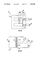
- FIG. 4 is a schematic diagram of the switch shown in FIGS. 3C and 3D.
- FIG. 5 is a circuit diagram of an alternative exemplary embodiment of a transformer made in accordance with the subject invention.
- the present invention is directed to the control of a transformer, such as one used to deliver controllable electric power to establish and maintain a welding arc.
- the illustrated transformer is constructed to provide an amplifying effect wherein changes in a relatively high output current are effected by controlling a relatively low shunt current.
- a transformer, designated generally as 100, constructed in accordance with the present invention includes a magnetic core 102, a primary coil 104, a secondary coil 106, and a shunt coil 108.
- Flux coupling with primary coil 104 follows a primary magnetic path 104A
- flux coupling with secondary coil 106 follows a secondary magnetic path 106A
- flux coupling with shunt coil 108 follows a shunt magnetic path 108A.
- Primary magnetic path 104A and secondary magnetic path 106A together form the main magnetic path of transformer 100.
- Shunt coil 108 is provided to allow the output of transformer 100 to be controlled electronically. More particularly, according to one method of the present invention the high current output of transformer 100 is used in a welding application and is controlled by controlling the induced AC current in shunt coil 108.
- the additional flux increases the output of transformer 100 because it is divided between shunt magnetic path 108A and secondary magnetic path 106A.
- the ratio of the flux in secondary magnetic path 106A to the flux in shunt magnetic path 108A, ⁇ sec / ⁇ shunt is equal to the ratio of the reluctance of shunt magnetic path 108A to the reluctance of secondary magnetic path 106A, R shunt /R sec .
- Transformer 100 is designed such that R shunt is much greater than R sec , therefore most of the additional flux follows secondary magnetic path 106A, coupling with secondary coil 106 and increasing the output of transformer 100.
- relatively small changes in ⁇ shunt effect relatively large changes in ⁇ sec and the output of transformer 100, and transformer 100 exhibits an amplifying effect with a gain of approximately ⁇ sec / ⁇ shunt .
- the magnitude of the output of transformer 100 is dependent on the amount of flux following secondary magnetic path 106A.
- the amount of flux following secondary magnetic path 106A is in turn responsive to the current flow through shunt coil 108.
- the output of transformer 100 may be controlled by controlling the current flow through shunt coil 108.
- control of the output is achieved by open-circuiting and close-circuiting shunt coil 108 for such times that the desired output is achieved. More particularly, shunt coil 108 is open-circuited at a first selected time in each AC cycle and close-circuited at a second selected time in each AC cycle. Thus, to increase the output of transformer 100 the length of time shunt coil 108 is close-circuited is increased, and to decrease the output of transformer 100 the length of time shunt coil 108 is open-circuited is increased, in either case by adjusting the time at which switching occurs.
- magnetic core 102 is comprised of a stack of magnetic "I" laminations, collectively and individually referred to as 110, and a stack of magnetic "E” laminations, collectively and individually referred to as 112, the latter having a shunt leg 114.
- Lamination stacks 110 and 112 are constructed by laminating magnetic plates together in accordance with conventional techniques and consist of any standard magnetic material. The magnetic material should be selected consistent with the concentration of magnetic flux lines and reasonable losses due to cycling of the magnetic domains within the material.
- magnetic core 102 could be comprised of a ferrite material.
- FIG. 1 The construction shown in the preferred embodiment of FIG. 1 was selected in order to have primary coil 104 and secondary coil 106 in close proximity to one another. The closeness of this proximity is a determining factor of the maximum output of the transformer. It is obvious to one skilled in the art that other arrangements are possible and more desirable for other applications.
- the number of turns and the size of the wire comprising coils 104, 106 and 108 is arrived at using conventional techniques.
- primary coil 104 is comprised of approximately 130 turns of number 8 AWG (American Wire Gauge) wire
- secondary coil 106 is comprised of approximately 30 turns of number 4 AWG wire
- shunt coil 108 is comprised of approximately 250 turns of number 10 AWG wire.
- Primary coil 104 and secondary coil 106 are wound on "I" lamination stack 110 such that they have a common axis of symmetry.
- Shunt coil 108 which is substantially coplanar with primary coil 104 and secondary coil 106, is wound about shunt leg 114 such that its axis of symmetry is perpendicular to the axis of symmetry shared by primary coil 104 and secondary coil 106.
- Shunt leg 114 is positioned such that the axis of symmetry of shunt coil 108 is about equidistant primary coil 104 and secondary coil 106.
- each "I" lamination 110 and "E” lamination stack 112 are suitably comprised of 140 24 gauge electrical steel I and E laminations, respectively, each stack having a height of about 3.5 inches.
- each "I” lamination 110 has a length of about 8.0 inches and a width of about 1.75 inches.
- Each "E” lamination 112 includes a pair of side legs 202 and 204, a base 206 and shunt leg 114. Legs 202 and 204, suitably about 5.8 inches long and about 1.75 inches wide are positioned perpendicular to and against "I" lamination stack 110.
- Base 206 is approximately 8.0 inches in length, about 1.75 inches wide, and substantially perpendicular to legs 114, 202 and 204.
- Leg 114 is about 1.2 inches wide and about 4.02 inches long, so as to form an air gap 208 between it and "I" lamination stack 110.
- air gap 208 is about 0.030 inches in length.
- air gap 208 could be formed by providing a notch in "I" lamination 110.
- air gap 208 in conjunction with the physical dimensions of magnetic core 102, determines the gain of the amplifier effect, thereby determining the minimum and maximum output current of transformer 100.
- the magnitudes of the magnetic reluctances of secondary magnetic path 106A and shunt magnetic path 108A determines the relative flux in each path and, therefore, the gain of the amplifier effect.
- the MMF, which is ⁇ * R, across two parallel branches of a magnetic circuit must be equal
- the gain of the amplifier effect, ⁇ sec / ⁇ shunt is equal to R shunt /R sec .
- the reluctances of secondary magnetic path 106A and shunt magnetic path 108A are tailored by properly selecting their respective cross sectional areas, lengths, and effective permeabilities.
- R sec the reluctance of secondary magnetic path 106A, is given by 1 sec /( ⁇ sec * A sec ), where ⁇ sec is the permeability of the material in secondary magnetic path 106A, and 1 sec and A sec are the mean length and cross sectional area of secondary magnetic path 106A, respectively.
- R shunt the reluctance of shunt magnetic path 108A, including air gap 208, is given by (1 shunt /( ⁇ shunt *A shunt ))+(1 gap /( ⁇ 0 *A eff )) where 1 shunt is the mean length of shunt magnetic path 108A less the length of air gap 208, ⁇ shunt is the permeability of the material in the shunt portion of the magnetic circuit, A shunt is the area of shunt leg 114, 1 gap is the length of air gap 208, ⁇ 0 is the permeability of air, and A eff is the effective area of air gap 208.
- a eff which may be approximated by adding the 1 gap to the dimensions defining A shunt , is approximately equal to A shunt and ⁇ 0 is a constant much less than ⁇ shunt , R shunt is predominantly determined by 1 gap .
- a desired value of R shunt may conveniently be obtained and, for a given R sec , a desired magnetic gain may also be conveniently obtained.
- air gap 208 could be filled with any material having a reluctance greater than the reluctance of magnetic core 102.
- air gap 208 and other physical characteristics of transformer 100, are chosen to provide reluctances in the secondary and shunt paths having a desirable ratio for the purpose of obtaining an output current range of 30 to 180 amps at an output voltage of up to 80 volts and having an acceptable waveform.
- the ratio of the shunt reluctance to the secondary reluctance may be tailored to suit a particular application.
- the ratio of the shunt reluctance to the secondary reluctance is approximately seven to one.
- an AC power source 302 and a load 304 are shown in addition to transformer 100 which includes, as well, a switch circuit 306 having terminals 308 and 312.
- AC power source 302 is connected to primary coil 104 and load 304 is connected to secondary coil 106 in a conventional manner.
- Switch circuit 306 controls the output current of transformer 100 by selectively open-circuiting and close-circuiting shunt coil 108. Specifically, a low resistance current path between terminal 308 and terminal 312 is closed at a first selected time in each AC cycle of the waveform induced in shunt coil 108 and opened at a second selected time in each AC cycle of the waveform induced in shunt coil 108. Preferably, the current path between 308 and 312 is an extremely low resistance path when close circuited. Regardless, the time at which the current path is opened and closed determines the current flow in shunt coil 108 and, therefore, the output of transformer 100.
- the output of transformer 100 is increased by moving the first selected time earlier or moving the second selected time later with respect to the zero crossing of AC voltage induced in the shunt coil 108. Likewise, the output of transformer 100 is decreased by moving the first selected time later or moving the second selected time earlier.
- switch circuit 306 may instead be responsive to other signals such as the waveform on primary coil 104 or an independently generated timing signal, and any timing device that provides a duty cycle may be used to trigger the switching of switch circuit 306.
- switch circuit 306 may be responsive to the magnitude of an input signal. Because of the periodic nature of the AC waveform induced on shunt coil 108, responding to the magnitude of the voltage induced on shunt coil 108 will result in switching at a given time in each AC cycle, thereby selecting the relative open and close circuited times.
- a phase control switch 306A (described in detail below with reference to FIG. 4) includes terminals 308A, 310A and 312A.
- a current path between terminals 308A and 312A is closed at a predetermined time relative to each zero crossing of the AC waveform applied to terminals 308A and 310A.
- the current path is opened at each zero crossing of the AC waveform applied to terminals 308A and 310A.
- the current induced in shunt coil 108 is circulated through load 304, thereby increasing the output power of the transformer.
- the shunt current may be added to the rectified output of the transformer by means of a unidirectional switching device, adding to the stability of the welding arc.
- phase control switch 306A provides a virtual short circuit between terminals 308A and 312A at a predetermined time relative to each zero crossing of the waveform applied to terminals 308A and 310A.
- a bi-directional thyristor 402 provided between terminals 308A and 312A, is caused to conduct at a predetermined time in each half cycle of the AC waveform applied to terminals 308A and 310A.
- Thyristor 402 will continue to conduct until it becomes reverse-biased when the polarity across terminals 308A and 310A reverses.
- the time at which thyristor 402 begins conducting relative to each zero crossing determines the relative "on” time and "off” time of current flow through shunt coil 108.
- the relative "on” time and “off” time of current flow through shunt coil 108 controls the flux through secondary magnetic path 106A and, therefore, the output of transformer 100.
- the predetermined time in each AC cycle at which thyristor 402 begins conducting is controlled by adjusting the resistance of a variable resistor 408.
- a capacitor 412 is charged by the voltage difference between terminals 308A and 310A, through variable resistor 408 and a resistor 404.
- the voltage on capacitor 412 becomes greater than the triggering threshold of a trigger 410, it sends a timing signal to a resistor 406 and thyristor 402, thereby causing thyristor 402 to conduct.
- the charging time of capacitor 412, and the time at which thyristor 402 begins conducting is dependent upon the RC time constant of resistor 404, variable resistor 408 and capacitor 412.
- the RC time constant may be adjusted, thereby controlling the length of time that thyristor 402 conducts and, therefore, the output of transformer 100.
- Phase control switch 306A is designed to eliminate the need for an independent source of power or reference voltage.
- the power to turn phase control switch 306A on and off is obtained directly from the voltage induced on shunt coil 108 and no reference voltage is needed because trigger 410 operates on the energy stored in capacitor 412.
- the present invention is suitable for welding applications which require a balanced output waveform as well as welding applications which require an unbalanced output waveform, such as TIG welding.
- a balanced output waveform is obtained by allowing thyristor 402 to conduct on both the positive and negative half-cycles of the voltage induced on shunt coil 108 and an unbalanced output waveform is provided by allowing thyristor 402 to conduct on only the positive or negative half-cycle.
- Selection between balanced and unbalanced output waveforms may be made using a selector switch 414, having terminals 416-422.
- terminal 416 When terminal 416 is connected to terminal 420, capacitor 412 is charged on both the positive and negative halves of the waveform, and thyristor 402 conducts on both positive and negative halves of the waveform.
- terminal 416 when terminal 416 is connected to terminal 422, capacitor 412 is short-circuited by a diode 426 on the negative half of the waveform and charges on only the positive half of the waveform.
- capacitor 412 is short-circuited by a diode 424 on the positive half of the waveform and charges on only the negative half of the waveform.
- Phase control switch 306A may be connected in alternative arrangements, such as that shown in FIG. 5. Referring to FIG. 5, shunt coil 108 and primary coil 104 are connected in series when phase control switch 306A is off. When phase control switch is triggered on, by the waveform on shunt coil 108, the current in primary coil 104 bypasses shunt coil 108, and the current in shunt coil 108 bypasses primary coil 104.
Landscapes
- Engineering & Computer Science (AREA)
- Power Engineering (AREA)
- Physics & Mathematics (AREA)
- Electromagnetism (AREA)
- General Physics & Mathematics (AREA)
- Radar, Positioning & Navigation (AREA)
- Automation & Control Theory (AREA)
- Arc Welding Control (AREA)
Abstract
Description
Claims (4)
Priority Applications (6)
| Application Number | Priority Date | Filing Date | Title |
|---|---|---|---|
| US07/661,471 US5187428A (en) | 1991-02-26 | 1991-02-26 | Shunt coil controlled transformer |
| EP19920907457 EP0530347A4 (en) | 1991-02-26 | 1992-02-24 | Shunt coil controlled transformer |
| CA002080461A CA2080461A1 (en) | 1991-02-26 | 1992-02-24 | Shunt coil controlled transformer |
| PCT/US1992/001464 WO1992015051A1 (en) | 1991-02-26 | 1992-02-24 | Shunt coil controlled transformer |
| US07/954,300 US5363035A (en) | 1991-02-26 | 1992-09-30 | Phase controlled transformer |
| US08/335,441 US5672963A (en) | 1991-02-26 | 1994-11-07 | Variable induction control led transformer |
Applications Claiming Priority (1)
| Application Number | Priority Date | Filing Date | Title |
|---|---|---|---|
| US07/661,471 US5187428A (en) | 1991-02-26 | 1991-02-26 | Shunt coil controlled transformer |
Related Child Applications (1)
| Application Number | Title | Priority Date | Filing Date |
|---|---|---|---|
| US07/954,300 Continuation-In-Part US5363035A (en) | 1991-02-26 | 1992-09-30 | Phase controlled transformer |
Publications (1)
| Publication Number | Publication Date |
|---|---|
| US5187428A true US5187428A (en) | 1993-02-16 |
Family
ID=24653743
Family Applications (2)
| Application Number | Title | Priority Date | Filing Date |
|---|---|---|---|
| US07/661,471 Expired - Fee Related US5187428A (en) | 1991-02-26 | 1991-02-26 | Shunt coil controlled transformer |
| US07/954,300 Expired - Lifetime US5363035A (en) | 1991-02-26 | 1992-09-30 | Phase controlled transformer |
Family Applications After (1)
| Application Number | Title | Priority Date | Filing Date |
|---|---|---|---|
| US07/954,300 Expired - Lifetime US5363035A (en) | 1991-02-26 | 1992-09-30 | Phase controlled transformer |
Country Status (4)
| Country | Link |
|---|---|
| US (2) | US5187428A (en) |
| EP (1) | EP0530347A4 (en) |
| CA (1) | CA2080461A1 (en) |
| WO (1) | WO1992015051A1 (en) |
Cited By (43)
| Publication number | Priority date | Publication date | Assignee | Title |
|---|---|---|---|---|
| EP0667205A1 (en) * | 1994-02-10 | 1995-08-16 | Miller Electric Manufacturing Company | Synchronized pulse arc starter and stabilizer for arc welding |
| WO1995024005A1 (en) * | 1994-03-04 | 1995-09-08 | Marelco Power Systems, Inc. | An electrically controllable inductor |
| US5513093A (en) * | 1994-03-11 | 1996-04-30 | Miller Electric Mfg. Co. | Reduced open circuit voltage power supply and method of producing therefor |
| US5525951A (en) * | 1992-06-22 | 1996-06-11 | Matsushita Electric Industrial Co., Ltd. | Choke coil |
| US5672963A (en) * | 1991-02-26 | 1997-09-30 | Illinois Tool Works Inc. | Variable induction control led transformer |
| US5731666A (en) * | 1996-03-08 | 1998-03-24 | Magnetek Inc. | Integrated-magnetic filter having a lossy shunt |
| US5804959A (en) * | 1997-02-18 | 1998-09-08 | Tabuchi Electric Company Of America | Shunt core transformer with a second secondary coil comprised of a ferrous material |
| US6261437B1 (en) | 1996-11-04 | 2001-07-17 | Asea Brown Boveri Ab | Anode, process for anodizing, anodized wire and electric device comprising such anodized wire |
| US6279850B1 (en) | 1996-11-04 | 2001-08-28 | Abb Ab | Cable forerunner |
| US6357688B1 (en) | 1997-02-03 | 2002-03-19 | Abb Ab | Coiling device |
| US6369470B1 (en) | 1996-11-04 | 2002-04-09 | Abb Ab | Axial cooling of a rotor |
| US6376775B1 (en) | 1996-05-29 | 2002-04-23 | Abb Ab | Conductor for high-voltage windings and a rotating electric machine comprising a winding including the conductor |
| US6396187B1 (en) | 1996-11-04 | 2002-05-28 | Asea Brown Boveri Ab | Laminated magnetic core for electric machines |
| US6417456B1 (en) | 1996-05-29 | 2002-07-09 | Abb Ab | Insulated conductor for high-voltage windings and a method of manufacturing the same |
| US6429563B1 (en) | 1997-02-03 | 2002-08-06 | Abb Ab | Mounting device for rotating electric machines |
| US6439497B1 (en) | 1997-02-03 | 2002-08-27 | Abb Ab | Method and device for mounting a winding |
| US6465979B1 (en) | 1997-02-03 | 2002-10-15 | Abb Ab | Series compensation of electric alternating current machines |
| US6525265B1 (en) | 1997-11-28 | 2003-02-25 | Asea Brown Boveri Ab | High voltage power cable termination |
| US6525504B1 (en) | 1997-11-28 | 2003-02-25 | Abb Ab | Method and device for controlling the magnetic flux in a rotating high voltage electric alternating current machine |
| US6577487B2 (en) | 1996-05-29 | 2003-06-10 | Asea Brown Boveri Ab | Reduction of harmonics in AC machines |
| US20030164245A1 (en) * | 2000-04-28 | 2003-09-04 | Claes Areskoug | Stationary induction machine and a cable therefor |
| US6646363B2 (en) | 1997-02-03 | 2003-11-11 | Abb Ab | Rotating electric machine with coil supports |
| US6801421B1 (en) * | 1998-09-29 | 2004-10-05 | Abb Ab | Switchable flux control for high power static electromagnetic devices |
| US6822363B2 (en) | 1996-05-29 | 2004-11-23 | Abb Ab | Electromagnetic device |
| US6825585B1 (en) | 1997-02-03 | 2004-11-30 | Abb Ab | End plate |
| US6828701B1 (en) | 1997-02-03 | 2004-12-07 | Asea Brown Boveri Ab | Synchronous machine with power and voltage control |
| US6831388B1 (en) | 1996-05-29 | 2004-12-14 | Abb Ab | Synchronous compensator plant |
| US6867674B1 (en) | 1997-11-28 | 2005-03-15 | Asea Brown Boveri Ab | Transformer |
| US6873080B1 (en) | 1997-09-30 | 2005-03-29 | Abb Ab | Synchronous compensator plant |
| US6885273B2 (en) | 2000-03-30 | 2005-04-26 | Abb Ab | Induction devices with distributed air gaps |
| US6891303B2 (en) | 1996-05-29 | 2005-05-10 | Abb Ab | High voltage AC machine winding with grounded neutral circuit |
| US6970063B1 (en) | 1997-02-03 | 2005-11-29 | Abb Ab | Power transformer/inductor |
| US6972505B1 (en) | 1996-05-29 | 2005-12-06 | Abb | Rotating electrical machine having high-voltage stator winding and elongated support devices supporting the winding and method for manufacturing the same |
| US6995646B1 (en) | 1997-02-03 | 2006-02-07 | Abb Ab | Transformer with voltage regulating means |
| US7019429B1 (en) | 1997-11-27 | 2006-03-28 | Asea Brown Boveri Ab | Method of applying a tube member in a stator slot in a rotating electrical machine |
| US7046492B2 (en) | 1997-02-03 | 2006-05-16 | Abb Ab | Power transformer/inductor |
| US7061133B1 (en) | 1997-11-28 | 2006-06-13 | Abb Ab | Wind power plant |
| US7141908B2 (en) | 2000-03-01 | 2006-11-28 | Abb Ab | Rotating electrical machine |
| US20100214091A1 (en) * | 2007-11-15 | 2010-08-26 | Endress + Hauser Process Solution Ag | Verfahren zum betreiben eines feldgerates, sowie kommunikationseinheit und feldgerat |
| US20110068888A1 (en) * | 2008-07-25 | 2011-03-24 | Ampower Technology Co., Ltd. | High voltage transformer employed in an inverter |
| US20120092116A1 (en) * | 2010-10-15 | 2012-04-19 | Ampower Technology Co., Ltd. | High voltage transformer |
| US20130009737A1 (en) * | 2009-12-18 | 2013-01-10 | Svend Erik Rocke | Transformer |
| CN111085767A (en) * | 2019-12-30 | 2020-05-01 | 桂林理工大学 | An electron beam cathode heating and voltage stabilization device |
Families Citing this family (10)
| Publication number | Priority date | Publication date | Assignee | Title |
|---|---|---|---|---|
| NO319424B1 (en) * | 2001-11-21 | 2005-08-08 | Magtech As | Method for Controllable Conversion of a Primary AC / Voltage to a Secondary AC / Voltage |
| US7023313B2 (en) * | 2003-07-16 | 2006-04-04 | Marvell World Trade Ltd. | Power inductor with reduced DC current saturation |
| US7307502B2 (en) * | 2003-07-16 | 2007-12-11 | Marvell World Trade Ltd. | Power inductor with reduced DC current saturation |
| US7489219B2 (en) * | 2003-07-16 | 2009-02-10 | Marvell World Trade Ltd. | Power inductor with reduced DC current saturation |
| US7760525B2 (en) * | 2003-08-21 | 2010-07-20 | Marvell World Trade Ltd. | Voltage regulator |
| US7872454B2 (en) * | 2003-08-21 | 2011-01-18 | Marvell World Trade Ltd. | Digital low dropout regulator |
| US8324872B2 (en) | 2004-03-26 | 2012-12-04 | Marvell World Trade, Ltd. | Voltage regulator with coupled inductors having high coefficient of coupling |
| US7190152B2 (en) * | 2004-07-13 | 2007-03-13 | Marvell World Trade Ltd. | Closed-loop digital control system for a DC/DC converter |
| TWI378478B (en) * | 2007-01-09 | 2012-12-01 | Mitsubishi Electric Corp | Reactor-jointed transformer |
| US10741094B2 (en) | 2016-06-30 | 2020-08-11 | Timpson Electrical & Aerial Services, LLC | High voltage training device and system and method thereof |
Citations (25)
| Publication number | Priority date | Publication date | Assignee | Title |
|---|---|---|---|---|
| AT96238B (en) * | 1922-10-23 | 1924-03-10 | Elin Ag Elek Ind Wien | Device for regulating the magnetic resistance of reactors and transformers. |
| US1902466A (en) * | 1927-05-28 | 1933-03-21 | Gen Electric | Apparatus for regulating alternating current circuits |
| US2765436A (en) * | 1950-07-28 | 1956-10-02 | Vickers Inc | Power transmission |
| US2827565A (en) * | 1954-02-17 | 1958-03-18 | Raytheon Mfg Co | Current regulators |
| US2844804A (en) * | 1955-07-06 | 1958-07-22 | Letourneau Westinghouse Compan | Control transformer |
| US2944208A (en) * | 1955-10-28 | 1960-07-05 | Raytheon Co | High reactance transformers |
| US2976478A (en) * | 1956-03-16 | 1961-03-21 | Aske Vernon Harold | Variable permeability magnetic circuit |
| US3172031A (en) * | 1961-06-01 | 1965-03-02 | Basic Products Corp | Saturable power modulator |
| US3253212A (en) * | 1961-10-24 | 1966-05-24 | Stabilac Pty Ltd | Ferro-resonant control elements and variable voltage power source incorporating same |
| US3361956A (en) * | 1963-12-16 | 1968-01-02 | Basic Products Corp | Voltage regulating transformer systems |
| US3447068A (en) * | 1966-12-20 | 1969-05-27 | Bell Telephone Labor Inc | Single core series-shunt ferroresonant voltage regulator with easily altered gap |
| US3456087A (en) * | 1965-08-10 | 1969-07-15 | Siltronics Inc | Power supply and automatic control system for high-speed electric discharge machining apparatus |
| US3553620A (en) * | 1967-09-14 | 1971-01-05 | Ibm | Combined transformer and indicator device |
| US3579088A (en) * | 1969-04-08 | 1971-05-18 | Taylor C Fletcher | Ferroresonant transformer with controllable flux |
| US3596038A (en) * | 1969-06-23 | 1971-07-27 | Everard M Williams | Power supply and automatic control system for gap discharge apparatus and the like |
| US3659191A (en) * | 1971-04-23 | 1972-04-25 | Westinghouse Electric Corp | Regulating transformer with non-saturating input and output regions |
| US3938030A (en) * | 1974-07-18 | 1976-02-10 | Cornwell Lionel B | Controllable power transferring device utilizing a short-circuited controlled reactance |
| US4032840A (en) * | 1975-07-17 | 1977-06-28 | Lebedev Vladimir Konstantinovi | Adjustable transformer |
| US4041431A (en) * | 1976-11-22 | 1977-08-09 | Ralph Ogden | Input line voltage compensating transformer power regulator |
| US4166992A (en) * | 1977-08-04 | 1979-09-04 | International Business Machines Corporation | Symmetrical structure for shunt controlled regulated transformer |
| US4177418A (en) * | 1977-08-04 | 1979-12-04 | International Business Machines Corporation | Flux controlled shunt regulated transformer |
| US4378522A (en) * | 1981-04-30 | 1983-03-29 | Suladze Robert N | Adjustable current source |
| US4737704A (en) * | 1939-12-01 | 1988-04-12 | Kalinnikov Semen A | Transformer for arc and plasma setups having broad current adjustment range |
| US4766365A (en) * | 1987-04-15 | 1988-08-23 | Hydro Quebec | Self-regulated transformer-inductor with air gaps |
| US4876638A (en) * | 1988-02-10 | 1989-10-24 | Electronic Research Group, Inc. | Low-noise switching power supply having variable reluctance transformer |
Family Cites Families (2)
| Publication number | Priority date | Publication date | Assignee | Title |
|---|---|---|---|---|
| US4414491A (en) * | 1981-08-10 | 1983-11-08 | Quietlite International, Ltd. | Current limiting power supply for electron discharge lamps |
| US4994952A (en) * | 1988-02-10 | 1991-02-19 | Electronics Research Group, Inc. | Low-noise switching power supply having variable reluctance transformer |
-
1991
- 1991-02-26 US US07/661,471 patent/US5187428A/en not_active Expired - Fee Related
-
1992
- 1992-02-24 WO PCT/US1992/001464 patent/WO1992015051A1/en not_active Application Discontinuation
- 1992-02-24 CA CA002080461A patent/CA2080461A1/en not_active Abandoned
- 1992-02-24 EP EP19920907457 patent/EP0530347A4/en not_active Withdrawn
- 1992-09-30 US US07/954,300 patent/US5363035A/en not_active Expired - Lifetime
Patent Citations (25)
| Publication number | Priority date | Publication date | Assignee | Title |
|---|---|---|---|---|
| AT96238B (en) * | 1922-10-23 | 1924-03-10 | Elin Ag Elek Ind Wien | Device for regulating the magnetic resistance of reactors and transformers. |
| US1902466A (en) * | 1927-05-28 | 1933-03-21 | Gen Electric | Apparatus for regulating alternating current circuits |
| US4737704A (en) * | 1939-12-01 | 1988-04-12 | Kalinnikov Semen A | Transformer for arc and plasma setups having broad current adjustment range |
| US2765436A (en) * | 1950-07-28 | 1956-10-02 | Vickers Inc | Power transmission |
| US2827565A (en) * | 1954-02-17 | 1958-03-18 | Raytheon Mfg Co | Current regulators |
| US2844804A (en) * | 1955-07-06 | 1958-07-22 | Letourneau Westinghouse Compan | Control transformer |
| US2944208A (en) * | 1955-10-28 | 1960-07-05 | Raytheon Co | High reactance transformers |
| US2976478A (en) * | 1956-03-16 | 1961-03-21 | Aske Vernon Harold | Variable permeability magnetic circuit |
| US3172031A (en) * | 1961-06-01 | 1965-03-02 | Basic Products Corp | Saturable power modulator |
| US3253212A (en) * | 1961-10-24 | 1966-05-24 | Stabilac Pty Ltd | Ferro-resonant control elements and variable voltage power source incorporating same |
| US3361956A (en) * | 1963-12-16 | 1968-01-02 | Basic Products Corp | Voltage regulating transformer systems |
| US3456087A (en) * | 1965-08-10 | 1969-07-15 | Siltronics Inc | Power supply and automatic control system for high-speed electric discharge machining apparatus |
| US3447068A (en) * | 1966-12-20 | 1969-05-27 | Bell Telephone Labor Inc | Single core series-shunt ferroresonant voltage regulator with easily altered gap |
| US3553620A (en) * | 1967-09-14 | 1971-01-05 | Ibm | Combined transformer and indicator device |
| US3579088A (en) * | 1969-04-08 | 1971-05-18 | Taylor C Fletcher | Ferroresonant transformer with controllable flux |
| US3596038A (en) * | 1969-06-23 | 1971-07-27 | Everard M Williams | Power supply and automatic control system for gap discharge apparatus and the like |
| US3659191A (en) * | 1971-04-23 | 1972-04-25 | Westinghouse Electric Corp | Regulating transformer with non-saturating input and output regions |
| US3938030A (en) * | 1974-07-18 | 1976-02-10 | Cornwell Lionel B | Controllable power transferring device utilizing a short-circuited controlled reactance |
| US4032840A (en) * | 1975-07-17 | 1977-06-28 | Lebedev Vladimir Konstantinovi | Adjustable transformer |
| US4041431A (en) * | 1976-11-22 | 1977-08-09 | Ralph Ogden | Input line voltage compensating transformer power regulator |
| US4166992A (en) * | 1977-08-04 | 1979-09-04 | International Business Machines Corporation | Symmetrical structure for shunt controlled regulated transformer |
| US4177418A (en) * | 1977-08-04 | 1979-12-04 | International Business Machines Corporation | Flux controlled shunt regulated transformer |
| US4378522A (en) * | 1981-04-30 | 1983-03-29 | Suladze Robert N | Adjustable current source |
| US4766365A (en) * | 1987-04-15 | 1988-08-23 | Hydro Quebec | Self-regulated transformer-inductor with air gaps |
| US4876638A (en) * | 1988-02-10 | 1989-10-24 | Electronic Research Group, Inc. | Low-noise switching power supply having variable reluctance transformer |
Cited By (51)
| Publication number | Priority date | Publication date | Assignee | Title |
|---|---|---|---|---|
| US5672963A (en) * | 1991-02-26 | 1997-09-30 | Illinois Tool Works Inc. | Variable induction control led transformer |
| US5525951A (en) * | 1992-06-22 | 1996-06-11 | Matsushita Electric Industrial Co., Ltd. | Choke coil |
| EP0667205A1 (en) * | 1994-02-10 | 1995-08-16 | Miller Electric Manufacturing Company | Synchronized pulse arc starter and stabilizer for arc welding |
| WO1995024005A1 (en) * | 1994-03-04 | 1995-09-08 | Marelco Power Systems, Inc. | An electrically controllable inductor |
| US5523673A (en) * | 1994-03-04 | 1996-06-04 | Marelco Power Systems, Inc. | Electrically controllable inductor |
| US5754034A (en) * | 1994-03-04 | 1998-05-19 | Marelco Power Systems, Inc. | Electrically controllable inductor |
| US5513093A (en) * | 1994-03-11 | 1996-04-30 | Miller Electric Mfg. Co. | Reduced open circuit voltage power supply and method of producing therefor |
| US5731666A (en) * | 1996-03-08 | 1998-03-24 | Magnetek Inc. | Integrated-magnetic filter having a lossy shunt |
| US6936947B1 (en) | 1996-05-29 | 2005-08-30 | Abb Ab | Turbo generator plant with a high voltage electric generator |
| US6940380B1 (en) | 1996-05-29 | 2005-09-06 | Abb Ab | Transformer/reactor |
| US6577487B2 (en) | 1996-05-29 | 2003-06-10 | Asea Brown Boveri Ab | Reduction of harmonics in AC machines |
| US6919664B2 (en) | 1996-05-29 | 2005-07-19 | Abb Ab | High voltage plants with electric motors |
| US6972505B1 (en) | 1996-05-29 | 2005-12-06 | Abb | Rotating electrical machine having high-voltage stator winding and elongated support devices supporting the winding and method for manufacturing the same |
| US6376775B1 (en) | 1996-05-29 | 2002-04-23 | Abb Ab | Conductor for high-voltage windings and a rotating electric machine comprising a winding including the conductor |
| US6906447B2 (en) | 1996-05-29 | 2005-06-14 | Abb Ab | Rotating asynchronous converter and a generator device |
| US6417456B1 (en) | 1996-05-29 | 2002-07-09 | Abb Ab | Insulated conductor for high-voltage windings and a method of manufacturing the same |
| US6894416B1 (en) | 1996-05-29 | 2005-05-17 | Abb Ab | Hydro-generator plant |
| US6891303B2 (en) | 1996-05-29 | 2005-05-10 | Abb Ab | High voltage AC machine winding with grounded neutral circuit |
| US6831388B1 (en) | 1996-05-29 | 2004-12-14 | Abb Ab | Synchronous compensator plant |
| US6822363B2 (en) | 1996-05-29 | 2004-11-23 | Abb Ab | Electromagnetic device |
| US6369470B1 (en) | 1996-11-04 | 2002-04-09 | Abb Ab | Axial cooling of a rotor |
| US6396187B1 (en) | 1996-11-04 | 2002-05-28 | Asea Brown Boveri Ab | Laminated magnetic core for electric machines |
| US6261437B1 (en) | 1996-11-04 | 2001-07-17 | Asea Brown Boveri Ab | Anode, process for anodizing, anodized wire and electric device comprising such anodized wire |
| US6279850B1 (en) | 1996-11-04 | 2001-08-28 | Abb Ab | Cable forerunner |
| US6357688B1 (en) | 1997-02-03 | 2002-03-19 | Abb Ab | Coiling device |
| US6970063B1 (en) | 1997-02-03 | 2005-11-29 | Abb Ab | Power transformer/inductor |
| US6825585B1 (en) | 1997-02-03 | 2004-11-30 | Abb Ab | End plate |
| US6828701B1 (en) | 1997-02-03 | 2004-12-07 | Asea Brown Boveri Ab | Synchronous machine with power and voltage control |
| US6465979B1 (en) | 1997-02-03 | 2002-10-15 | Abb Ab | Series compensation of electric alternating current machines |
| US7046492B2 (en) | 1997-02-03 | 2006-05-16 | Abb Ab | Power transformer/inductor |
| US6439497B1 (en) | 1997-02-03 | 2002-08-27 | Abb Ab | Method and device for mounting a winding |
| US6429563B1 (en) | 1997-02-03 | 2002-08-06 | Abb Ab | Mounting device for rotating electric machines |
| US6995646B1 (en) | 1997-02-03 | 2006-02-07 | Abb Ab | Transformer with voltage regulating means |
| US6646363B2 (en) | 1997-02-03 | 2003-11-11 | Abb Ab | Rotating electric machine with coil supports |
| US5804959A (en) * | 1997-02-18 | 1998-09-08 | Tabuchi Electric Company Of America | Shunt core transformer with a second secondary coil comprised of a ferrous material |
| US6873080B1 (en) | 1997-09-30 | 2005-03-29 | Abb Ab | Synchronous compensator plant |
| US7019429B1 (en) | 1997-11-27 | 2006-03-28 | Asea Brown Boveri Ab | Method of applying a tube member in a stator slot in a rotating electrical machine |
| US6867674B1 (en) | 1997-11-28 | 2005-03-15 | Asea Brown Boveri Ab | Transformer |
| US6525265B1 (en) | 1997-11-28 | 2003-02-25 | Asea Brown Boveri Ab | High voltage power cable termination |
| US6525504B1 (en) | 1997-11-28 | 2003-02-25 | Abb Ab | Method and device for controlling the magnetic flux in a rotating high voltage electric alternating current machine |
| US7061133B1 (en) | 1997-11-28 | 2006-06-13 | Abb Ab | Wind power plant |
| US6801421B1 (en) * | 1998-09-29 | 2004-10-05 | Abb Ab | Switchable flux control for high power static electromagnetic devices |
| US7141908B2 (en) | 2000-03-01 | 2006-11-28 | Abb Ab | Rotating electrical machine |
| US6885273B2 (en) | 2000-03-30 | 2005-04-26 | Abb Ab | Induction devices with distributed air gaps |
| US20030164245A1 (en) * | 2000-04-28 | 2003-09-04 | Claes Areskoug | Stationary induction machine and a cable therefor |
| US7045704B2 (en) | 2000-04-28 | 2006-05-16 | Abb Ab | Stationary induction machine and a cable therefor |
| US20100214091A1 (en) * | 2007-11-15 | 2010-08-26 | Endress + Hauser Process Solution Ag | Verfahren zum betreiben eines feldgerates, sowie kommunikationseinheit und feldgerat |
| US20110068888A1 (en) * | 2008-07-25 | 2011-03-24 | Ampower Technology Co., Ltd. | High voltage transformer employed in an inverter |
| US20130009737A1 (en) * | 2009-12-18 | 2013-01-10 | Svend Erik Rocke | Transformer |
| US20120092116A1 (en) * | 2010-10-15 | 2012-04-19 | Ampower Technology Co., Ltd. | High voltage transformer |
| CN111085767A (en) * | 2019-12-30 | 2020-05-01 | 桂林理工大学 | An electron beam cathode heating and voltage stabilization device |
Also Published As
| Publication number | Publication date |
|---|---|
| CA2080461A1 (en) | 1992-08-27 |
| EP0530347A4 (en) | 1993-12-22 |
| EP0530347A1 (en) | 1993-03-10 |
| US5363035A (en) | 1994-11-08 |
| WO1992015051A1 (en) | 1992-09-03 |
Similar Documents
| Publication | Publication Date | Title |
|---|---|---|
| US5187428A (en) | Shunt coil controlled transformer | |
| US4206434A (en) | Regulating transformer with magnetic shunt | |
| JPS6040171B2 (en) | variable inductor | |
| US5672963A (en) | Variable induction control led transformer | |
| US3612988A (en) | Flux-gated voltage regulator | |
| EP1704636B1 (en) | Variable ac voltage regulation control method and apparatus | |
| US3603864A (en) | Current dependent filter inductance | |
| US6885272B1 (en) | Permanent magnetic core device | |
| US4652771A (en) | Oscillating flux transformer | |
| JPH02503621A (en) | Non-saturated magnetic amplification controller | |
| US3418563A (en) | Single-phase transformer for electric arc welding | |
| US3763413A (en) | Flux amplifier circuits for controlling induction motors and the like | |
| US5117214A (en) | Integrated magnetic power converter core | |
| JPS59124705A (en) | composite tripod transformer | |
| CA2158005A1 (en) | Controlled transformer | |
| RU2069610C1 (en) | Arc-welding single-phase rectifier | |
| SU1148507A1 (en) | Controllable transformer | |
| JPH0361205B2 (en) | ||
| SU928455A1 (en) | Electromagnetic relay with braking | |
| JPS59125122A (en) | Non-contact transformer relay switch using a composite tripod transformer | |
| JPH085534Y2 (en) | Variable reactor for electric power | |
| CA1051517A (en) | Controlled ferroresonant transformer regulated power supply | |
| JPS58129516A (en) | AC power phase control circuit using a leaky three-legged transformer | |
| JPH0568187B2 (en) | ||
| JPS59221718A (en) | AC power phase control circuit using a leaky tripod transformer |
Legal Events
| Date | Code | Title | Description |
|---|---|---|---|
| AS | Assignment |
Owner name: MILLER ELECTRIC MFG. CO., A CORP OF WI, WISCONSIN Free format text: ASSIGNMENT OF ASSIGNORS INTEREST.;ASSIGNORS:HUTCHISON, RICHARD M.;CORRIGALL, DON J.;REEL/FRAME:005624/0131 Effective date: 19910212 |
|
| FEPP | Fee payment procedure |
Free format text: PAYOR NUMBER ASSIGNED (ORIGINAL EVENT CODE: ASPN); ENTITY STATUS OF PATENT OWNER: LARGE ENTITY |
|
| AS | Assignment |
Owner name: ILLINOIS TOOL WORKS INC., ILLINOIS Free format text: ASSIGNMENT OF ASSIGNORS INTEREST;ASSIGNOR:MILLER ELECTRIC MFG. CO.;REEL/FRAME:007986/0507 Effective date: 19950517 |
|
| FPAY | Fee payment |
Year of fee payment: 4 |
|
| FPAY | Fee payment |
Year of fee payment: 8 |
|
| REMI | Maintenance fee reminder mailed | ||
| LAPS | Lapse for failure to pay maintenance fees | ||
| STCH | Information on status: patent discontinuation |
Free format text: PATENT EXPIRED DUE TO NONPAYMENT OF MAINTENANCE FEES UNDER 37 CFR 1.362 |
|
| FP | Lapsed due to failure to pay maintenance fee |
Effective date: 20050216 |