EP1002371B1 - Multi-tuner receiver - Google Patents
Multi-tuner receiver Download PDFInfo
- Publication number
- EP1002371B1 EP1002371B1 EP98900035A EP98900035A EP1002371B1 EP 1002371 B1 EP1002371 B1 EP 1002371B1 EP 98900035 A EP98900035 A EP 98900035A EP 98900035 A EP98900035 A EP 98900035A EP 1002371 B1 EP1002371 B1 EP 1002371B1
- Authority
- EP
- European Patent Office
- Prior art keywords
- frequency
- tuner
- oscillator
- signal
- tun2
- Prior art date
- Legal status (The legal status is an assumption and is not a legal conclusion. Google has not performed a legal analysis and makes no representation as to the accuracy of the status listed.)
- Expired - Lifetime
Links
- 230000010355 oscillation Effects 0.000 claims abstract description 43
- 238000000034 method Methods 0.000 claims description 4
- 101100339482 Colletotrichum orbiculare (strain 104-T / ATCC 96160 / CBS 514.97 / LARS 414 / MAFF 240422) HOG1 gene Proteins 0.000 description 13
- 230000008901 benefit Effects 0.000 description 12
- 101100171060 Caenorhabditis elegans div-1 gene Proteins 0.000 description 10
- 101100184148 Xenopus laevis mix-a gene Proteins 0.000 description 6
- 238000010586 diagram Methods 0.000 description 6
- 230000008878 coupling Effects 0.000 description 4
- 238000010168 coupling process Methods 0.000 description 4
- 238000005859 coupling reaction Methods 0.000 description 4
- 230000002452 interceptive effect Effects 0.000 description 4
- 101100345673 Xenopus laevis mix-b gene Proteins 0.000 description 3
- 230000006870 function Effects 0.000 description 3
- 238000006243 chemical reaction Methods 0.000 description 2
- 239000013078 crystal Substances 0.000 description 2
- 230000004075 alteration Effects 0.000 description 1
- 230000000903 blocking effect Effects 0.000 description 1
- 230000015556 catabolic process Effects 0.000 description 1
- 230000008859 change Effects 0.000 description 1
- 238000006731 degradation reaction Methods 0.000 description 1
- 230000001419 dependent effect Effects 0.000 description 1
- 230000009977 dual effect Effects 0.000 description 1
- 230000006698 induction Effects 0.000 description 1
- 239000002184 metal Substances 0.000 description 1
- 230000008569 process Effects 0.000 description 1
- 230000005855 radiation Effects 0.000 description 1
- 230000007480 spreading Effects 0.000 description 1
- 230000001629 suppression Effects 0.000 description 1
- 230000002194 synthesizing effect Effects 0.000 description 1
- 230000000007 visual effect Effects 0.000 description 1
Images


Classifications
-
- H—ELECTRICITY
- H04—ELECTRIC COMMUNICATION TECHNIQUE
- H04N—PICTORIAL COMMUNICATION, e.g. TELEVISION
- H04N5/00—Details of television systems
- H04N5/44—Receiver circuitry for the reception of television signals according to analogue transmission standards
- H04N5/4446—IF amplifier circuits specially adapted for B&W TV
-
- H—ELECTRICITY
- H03—ELECTRONIC CIRCUITRY
- H03J—TUNING RESONANT CIRCUITS; SELECTING RESONANT CIRCUITS
- H03J1/00—Details of adjusting, driving, indicating, or mechanical control arrangements for resonant circuits in general
- H03J1/0008—Details of adjusting, driving, indicating, or mechanical control arrangements for resonant circuits in general using a central processing unit, e.g. a microprocessor
- H03J1/0058—Details of adjusting, driving, indicating, or mechanical control arrangements for resonant circuits in general using a central processing unit, e.g. a microprocessor provided with channel identification means
- H03J1/0083—Details of adjusting, driving, indicating, or mechanical control arrangements for resonant circuits in general using a central processing unit, e.g. a microprocessor provided with channel identification means using two or more tuners
-
- H—ELECTRICITY
- H04—ELECTRIC COMMUNICATION TECHNIQUE
- H04B—TRANSMISSION
- H04B15/00—Suppression or limitation of noise or interference
- H04B15/02—Reducing interference from electric apparatus by means located at or near the interfering apparatus
- H04B15/04—Reducing interference from electric apparatus by means located at or near the interfering apparatus the interference being caused by substantially sinusoidal oscillations, e.g. in a receiver or in a tape-recorder
-
- H—ELECTRICITY
- H04—ELECTRIC COMMUNICATION TECHNIQUE
- H04N—PICTORIAL COMMUNICATION, e.g. TELEVISION
- H04N21/00—Selective content distribution, e.g. interactive television or video on demand [VOD]
- H04N21/40—Client devices specifically adapted for the reception of or interaction with content, e.g. set-top-box [STB]; Operations thereof
- H04N21/41—Structure of client; Structure of client peripherals
- H04N21/426—Internal components of the client ; Characteristics thereof
- H04N21/42607—Internal components of the client ; Characteristics thereof for processing the incoming bitstream
- H04N21/4263—Internal components of the client ; Characteristics thereof for processing the incoming bitstream involving specific tuning arrangements, e.g. two tuners
-
- H—ELECTRICITY
- H04—ELECTRIC COMMUNICATION TECHNIQUE
- H04N—PICTORIAL COMMUNICATION, e.g. TELEVISION
- H04N21/00—Selective content distribution, e.g. interactive television or video on demand [VOD]
- H04N21/40—Client devices specifically adapted for the reception of or interaction with content, e.g. set-top-box [STB]; Operations thereof
- H04N21/43—Processing of content or additional data, e.g. demultiplexing additional data from a digital video stream; Elementary client operations, e.g. monitoring of home network or synchronising decoder's clock; Client middleware
- H04N21/431—Generation of visual interfaces for content selection or interaction; Content or additional data rendering
- H04N21/4312—Generation of visual interfaces for content selection or interaction; Content or additional data rendering involving specific graphical features, e.g. screen layout, special fonts or colors, blinking icons, highlights or animations
-
- H—ELECTRICITY
- H01—ELECTRIC ELEMENTS
- H01L—SEMICONDUCTOR DEVICES NOT COVERED BY CLASS H10
- H01L2924/00—Indexing scheme for arrangements or methods for connecting or disconnecting semiconductor or solid-state bodies as covered by H01L24/00
- H01L2924/30—Technical effects
- H01L2924/301—Electrical effects
- H01L2924/3025—Electromagnetic shielding
-
- H—ELECTRICITY
- H04—ELECTRIC COMMUNICATION TECHNIQUE
- H04B—TRANSMISSION
- H04B2215/00—Reducing interference at the transmission system level
- H04B2215/064—Reduction of clock or synthesizer reference frequency harmonics
-
- H—ELECTRICITY
- H04—ELECTRIC COMMUNICATION TECHNIQUE
- H04N—PICTORIAL COMMUNICATION, e.g. TELEVISION
- H04N5/00—Details of television systems
- H04N5/44—Receiver circuitry for the reception of television signals according to analogue transmission standards
- H04N5/445—Receiver circuitry for the reception of television signals according to analogue transmission standards for displaying additional information
- H04N5/45—Picture in picture, e.g. displaying simultaneously another television channel in a region of the screen
Definitions
- the invention relates to a receiver comprising at least two tuners for concurrent reception of mutually different signals.
- the invention also relates to a multimedia apparatus and an add-on card comprising such a receiver.
- the Philips television (TV) set type 32PW9761 comprises two tuner modules for allowing a concurrent display of two mutually different TV programs.
- TV programs are broadcast at various respective radio frequencies in a range from, say, 45 MHz to 860 MHz.
- the broadcast TV programs enter the TV set via a radio frequency inlet and are supplied to the two tuner modules via a splitter in the TV set.
- Each of the two tuner modules has a shielded encasing which houses an oscillator and a mixer for converting a radio frequency to an intermediate frequency of, say, 40 MHz.
- the respective oscillators have adjustable oscillation frequencies.
- An oscillation frequency determines which radio frequency, and therefore which broadcast TV program, is converted to the 40 Mhz intermediate frequency for further processing so as to be displayed. If, for example, the oscillation frequency is 500 MHz, a TV program which is broadcast at a 460 MHz radio frequency is converted to the 40 MHz intermediate frequency and can be displayed as a result.
- DE-3443859-A1 discloses a receiver with frequency synthesizing and two receiver systems.
- a first one of the receiver systems changes its oscillation frequency within a frequency band in which the receiving frequency of the other receiver system occurs.
- the first one of the receiver systems selects a desired receiving station with a phase locked loop circuit and a control circuit.
- the control circuit controls the channel selection of the first one of the receiver systems to change its oscillator frequency such that the oscillation frequency does not occur in a frequency range which incorporates the receiving frequency and frequencies near to the receiving frequency of the other receiver.
- US-5285284-A1 discloses a television receiver with a sub-picture tuner and a main-picture tuner. Both the sub-picture tuner and the main-picture tuner may select separately a receiving signal by changing the respective oscillation frequencies with channel selection control signals. These varying oscillation frequencies are generated with a PLL frequency-synthesizer circuit.
- the PLL comprises a programmable frequency divider which divides a fixed reference oscillator frequency with a controllable number to obtain a selectable frequency of the oscillator signal. This oscillator signal is supplied to the mixer, and has a frequency required for receiving a particular channel. If the sub-picture tuner picture is not displayed, the sub-picture tuner is still active. To prevent interference from the sub-picture tuner to the main-picture tuner, the oscillation frequency of the sub-picture tuner is set at a fixed frequency higher than the highest frequency of the channels to be received by the main-picture tuner.
- EP-0595314-A1 discloses a broadcast receiver which comprises a first audio-tuner which receives a broadcast channel to be made audible at a loudspeaker, and a second audio-tuner which checks the signal quality of the same broadcast on alternative channels.
- the second tuner does not disturb the first tuner by preventing the local oscillator frequency of the second tuner to occur in frequency bands wherein the first tuner would be disturbed.
- Claims 1 define receivers in accordance with the invention.
- Claims 7, 4, 5 and 6 define a method of receiving, a multimedia apparatus, an add-on card and a single shielded encasing, respectively, all in accordance with the invention. Additional features which may be optionally used to implement the invention to advantage are defined in the dependent Claims.
- the invention takes the following aspects into consideration. Up to the present, the demand for receivers which can concurrently receive mutually different signals has been relatively low. To give an example, of the total number of TV sets sold, only a relatively small percentage has two tuners to provide, for example, a picture-in-picture (PIP) function. For that reason, it is cost-efficient at present to implement PIP TV sets in a background-art manner. That is, two separate tuner modules are used which are also applicable individually in many other types of TV sets and, are produced in relatively large quantities, which means that they are relatively cheap.
- PIP picture-in-picture
- two or more tuners are merged into one module. If the two or more tuners are merged, various components may be shared by the two or more tuners such as, for example, crystals, integrated circuits, printed wire boards, metalware, connectors, and pin blocks. Costs which will be saved if various components are shared may outweigh costs related to merging the two or more tuners into one module once the demand for receivers of the type under discussion is sufficiently high.
- Fig. 1 illustrates the basic principle of the invention.
- at least two tuners TUN1, TUN2 are merged into one module MOD.
- Fig. 1 shows two tuners TUN1, TUN2, further tuners may be merged into the same module MOD.
- Fig. 2 illustrates that each of the two tuners TUN1, TUN2 has an oscillator OSC coupled to a mixer MIX for converting a signal at a radio frequency to an intermediate frequency.
- Fig. 2 also illustrates the following additional feature.
- the oscillator of each of the two tuners has an oscillation frequency, Fosc1 or Fosc2, which does not coincide with the radio frequency, RF2 or RF1 or any sub-harmonic of the radio frequency of the signal received by the respective other tuner. This preferably applies substantially throughout respective tuning ranges of the two tuners TUN1, TUN2.
- the Fig. 2 feature is based on the following considerations.
- the two tuners TUN1, TUN2 which are merged into one module may interfere with each other.
- the oscillator of one of the two tuners may interfere with the signal received by the other tuner.
- An oscillator signal may propagate to various points in the receiver in many different ways. For example, it may propagate by means of induction in metal parts and by means of crosstalk into printed circuit board tracks which carry, for example, switching signals and varicap voltages.
- the overall propagation attenuation which the oscillator signal experiences is often highly unpredictable and, moreover, it may vary strongly as a function of frequency. This is an important fact, since the oscillator signal may not only comprise a fundamental frequency component but harmonic frequency components as well. The amplitude of a harmonic frequency component may therefore be higher than that of the fundamental frequency component at certain points in the receiver.
- Another solution could be to shield the oscillators electromagnetically.
- shielding is relatively expensive and, in some cases, it may even be insufficiently effective.
- the following example is given as an illustration.
- an interference distance of at least 60 dB is desirable.
- the level of a TV signal received by a tuner is 1 mV, which is a typical value
- the level of an interfering signal may not exceed 1 ⁇ V.
- the level of the oscillator signal in another tuner is 1 V, which is a typical value
- a 120 dB attenuation is needed between the two tuners. If the two tuners are merged into one module, any internal shielding for providing such attenuation, if feasible at all, will be costly and also difficult to design.
- Yet another solution could be to block reception for radio-frequency combinations at which the two tuners TUN 1, TUN2 would mutually interfere. This may be achieved by means of, for example, a suitably programmed computer which controls the two tuners TUN1, TUN2.
- a suitably programmed computer which controls the two tuners TUN1, TUN2.
- harmonic frequency components of oscillator signals need to be taken into account, it may be necessary to block reception for relatively many radio-frequency combinations. In that case, end users will be stuck with a relatively constrained variety of signals which can be received concurrently.
- Fig. 2 If the Fig. 2 feature is applied, neither the fundamental frequency component nor any harmonic frequency component of an oscillator signal in any of the two tuners TUN1 or TUN2 will interfere directly with the signal being received by the respective other tuner, TUN2 or TUN1.
- the oscillators OSC1, OSC2 are therefore allowed to operate at signal levels which provide a satisfactory performance in terms of noise and stability. What is more, this does not require any relatively elaborate shielding, nor does it require a blocking of reception for relatively many radio-frequency combinations.
- the Fig. 2 feature contributes to quality and versatility of reception and cost-efficiency, either in combination or on its own.
- the Fig. 2 feature will provide an additional advantage if a splitter is used to apply signals to the two tuners TUN 1,TUN2 from a common terminal. In that case the splitter need not provide high attenuation between the two tuners TUN1,TUN2 in order to prevent mutual interference. For that reason the splitter may be realized with relatively few active components, or it may even be realized without any active components. Active components consume power and produce noise and distortion. Thus the Fig. 2. feature allows of a relatively power-efficient, noiseless and distortionless splitter. It should be noted that these advantages will also be obtained if two tuners are separate, as in the background art.
- Fig. 3a illustrates the following additional feature.
- the oscillation frequency Fosc1 in tuner TUN1 exceeds the highest possible radio frequency RFmax2 which tuner TUN2 can receive. This preferably applies substantially throughout the tuning range of the tuner TUN1.
- the Fig. 3a feature is based on the following considerations. If the tuner TUN1 needs to be tunable throughout a relatively wide tuning range, it may be difficult to avoid coincidence of the oscillation frequency Fosc1 with the radio frequency RF2, or any sub-harmonic of the radio frequency RF2, of the signal received by tuner TUN2. Relatively complicated and hence costly measures may be needed to avoid such coincidence. However, if the Fig. 3a feature is applied, any such coincidence will be excluded by definition. Thus, the Fig. 3a feature contributes to cost-efficiency, in particular if the tuner TUN1 needs to be tuned through a relatively wide tuning range.
- Fig. 3b illustrates the following additional feature.
- the oscillation frequency, Fosc1 or Fosc2 in each of the two tuners exceeds the highest possible radio frequency, RFmax2 or RFmax1, respectively, which the other tuner can receive.
- the Fig. 3b feature is effectively an addition to the Fig. 3a feature.
- the addition is that the oscillation frequency Fosc2 in tuner TUN2 also exceeds the highest possible radio frequency RFmax1 which tuner TUN1 can receive.
- the Fig. 3b feature contributes to cost-efficiency, in particular if the two tuners TUN1, TUN2 both need to be tuned through a relatively wide tuning range.
- the tuner TUN1 receives the signal with the lower radio frequency and that consequently the tuner TUN2 receives the signal with the higher radio frequency.
- the oscillation frequency Fosc2 in the tuner TUN2 lies above the radio frequency RF2 of the signal received by this tuner, it will certainly exceed the radio frequency RF1 of the signal received by the tuner TUN1.
- the overall result will be that the oscillation frequency Fosc1 or Fosc2 in each of the two tuners will exceed the radio frequency RF2 or RF1, respectively, received by the other tuner. Consequently, neither the fundamental components nor any harmonic components of the oscillation signals can interfere with the signals received.
- the Fig. 3a feature can provide advantages similar to those of the Fig. 3b feature.
- the Fig. 3b feature may be preferable over the Fig. 3a feature for the following reason. Assuming that two signals S(X) and S(Y) are concurrently received, the signal S(Y) will have a higher radio frequency than signal S(X). The reception signal S(Y) needs to be discontinued in favour of a different signal S(Z) which has a lower radio frequency than S(X). The following will happen in the case of Fig. 3a with the provisions as described above.
- the tuner TUN2 will have to take over the reception of signal S(X), which is maintained, from the tuner TUN1. Such a take-over is needed in view of the higher-lower radio frequency relation. The take-over may cause an interruption in the reception of signal S(X). By contrast, however, no take-over will be needed if the Fig. 3b feature is applied.
- the Fig. 3b feature allows of an uninterrupted reception while changing any concurrent reception.
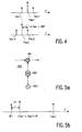
- Fig. 4 illustrates the following additional feature.
- the difference ⁇ Fosc between the oscillation frequencies Fosc1, Fosc2 in the two tuners TUN1, TUN2 exceeds an intermediate frequency bandwidth BWIF. This preferably applies substantially throughout the respective tuning ranges of the two tuners TUN 1, TUN2.
- the Fig. 4 feature is based on the following considerations.
- the oscillators OSC1, OSC2 may phase-modulate each other as a result of mutual electro-magnetic coupling. This will cause the oscillator signals to have sidebands.
- Fig. 4 shows sidebands Fsb+1, Fsb-1 belonging to oscillator OSC1 and sidebands Fsb+2,Fsb-2 belonging to oscillator OSC2.
- the sidebands are located at + ⁇ Fosc and - ⁇ Fosc from the oscillation frequencies Fosc1, Fosc2.
- the sidebands of each oscillator signal will mix with the respective signal received.
- the signals received which have been converted to the respective intermediate frequencies will also have sidebands located at + ⁇ Fosc and - ⁇ Fosc from these respective intermediate frequencies.
- the Fig. 4 feature counters mutual interference between the two tuners TUN1,TUN2 which may arise as a result of mutual electromagnetic coupling of their oscillators. Consequently, there will be relatively little need to counter such mutual electromagnetic coupling with measures such as, for example, providing internal shielding or improving the quality Q of an oscillator tank circuit. Such measures are relatively costly, in particular at relatively high frequencies. Hence the Fig. 4 feature contributes to cost-efficiency.
- the sidebands Fsb+,Fsb- could cause intermodulation products which may impair reception.
- the respective sidebands will generally have such a small-amplitude that, in many cases, this form of mutual interference may be disregarded.
- the amplitude of the respective sidebands Fsb+,Fsb- will decrease as the difference ⁇ Fosc between the oscillator frequencies Fosc1, Fosc2 increases.
- any harmonics of the oscillation frequencies Fosc1, Fosc2 do not substantially contribute to any mutual phase modulation of the oscillators OSC1, OSC2.
- there will be little or no mutual phase modulation if one of the oscillator frequencies, Fosc1 or Fosc2, is relatively close to a harmonic of the respective other oscillator frequency, Fosc2 or Fosc1. Consequently, if the frequency ranges of the oscillators OSC1, OSC2 do not overlap, any skip during an autosearch will not be necessary.
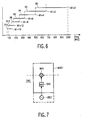
- Fig. 5a illustrates the following additional feature.
- a frequency divider DIV1 is coupled between the oscillator OSC1 and the mixer MIX1 in the tuner TUN 1.
- the frequency divider DIV1 generates a sub-harmonic of the oscillator signal. In principle, the sub-harmonic may interfere with the signal received by the tuner TUN2, not shown in Fig. 5a.
- the divider DIV1 and any circuitry coupling it to mixer MIX1 should be regarded as potentially interfering transmitters. However, with proper design, these potentially interfering transmitters will be appreciably weaker than the potentially interfering transmitter which the oscillator OSC1 would have been if the invention were not used. Consequently, the Fig. 5a feature does not stand in the way of a merging of two tuners in a manner which would not have been possible in the background art.
- Fig. 5b is a frequency diagram showing the radio frequency RF1, the oscillation frequency Fosc1, and a mixing frequency Fmix1.
- the mixing frequency Fmix is the oscillation frequency Fosc1 divided by N1, N1 being the division factor of the frequency divider DIV1.
- Fig. 5b also shows the intermediate frequency IF1 which is the difference between the mixing frequency Fmix1 and the radio frequency RF1.
- an advantage of the Fig. 5a feature is as follows. It allows the oscillation frequency Fosc1 to be such that a mutual interference between the two tuners TUN1, TUN2, as described in the foregoing, can be countered by a suitable choice of the division factor N1 of the frequency divider DIV 1. If in addition a frequency divider is also coupled between the oscillator OSC2 and the mixer MIX2 in the tuner TUN2, all shown in Fig. 1, this will provide a greater number of possibilities to counter mutual interference. The division factor of the latter divider introduces, as it were, an extra degree of freedom to achieve this.
- the Fig. 5a feature is neither essential to the invention, nor is it essential to any of the other features described above.
- the oscillation frequency Fosc1 shown in Fig. 5b may be directly applied to the mixer MIX1 without any frequency division. However, in that case the intermediate frequency would be the difference between the oscillation frequency Fosc1 and the radio frequency RF1. Consequently, the intermediate frequency would be higher. Circuitry for processing relatively high intermediate frequency signals is relatively costly, power-consuming and/or critical. Consequently, because the Fig. 5a feature allows of a relatively low intermediate frequency, it provide cost-efficiency, energy-efficiency and robustness.
- Fig. 6 illustrates the following additional feature.
- the division factor N1 of the frequency divider DIV1 shown in Fig. 5a is adjustable.
- the frequency divider DIV1 can be adjusted to have any of these division factors, it allows of the mixing of frequencies through a range from 62,5 MHz to 1000 MHz. If, however, the division factor N1 were fixed, the oscillator OSC1 would have to be tunable over a wider range, to allow a similar choice of mixing frequencies.
- the oscillator OSC1 This would make it more difficult, or even impossible, to realize the oscillator OSC1.
- several tunable oscillators could be used, each tunable oscillator covering a certain portion of the range of mixing frequencies. This solution is common in TVs where, for example, oscillators are used for the bands VHF-low, VHF-high and UHF, respectively.
- the Fig. 6 feature however, allows tuning through a relatively wide frequency range with a single oscillator which needs only to be tuned over a relatively narrow frequency range. Consequently, the Fig. 6 feature contributes to cost-efficiency.
- Fig. 6 also illustrates the following advantageous additional feature.
- Over a substantial portion of the range of mixing frequencies namely between 83.33 MHz and 666.67 Mhz, there is more than one oscillator frequency with which a certain mixing frequency can be obtained.
- there is a choice of oscillator frequencies for a certain mixing frequency This choice allows the oscillator frequency Fosc1 in the tuner TUN1 to be relatively far removed from the oscillator frequency Fosc2 in the tuner TUN2, thereby countering mutual interference.
- the oscillators OSC1, OSC2 operate in respective frequency ranges which overlap.
- a suitably chosen division factor N1 can prevent the oscillators OSC1,OSC2 from being too close together in frequency.
- an adjustable frequency divider is also coupled between the oscillator OSC2 and the mixer MIX2 in tuner TUN2, there will be an even greater choice in keeping the oscillation frequencies Fosc1, Fosc2 apart.
- Suitable software may be used to choose the optimal division factor, or division factors, in any given case.
- the oscillation frequencies Fosc 1, Fosc2 will be spaced apart by an amount which is N times the distance between the two adjacent radio-frequency channels, N being the identical division factor of the dividers DIV1, DIV2.
- N being the identical division factor of the dividers DIV1, DIV2.
- Fig. 7 illustrates the following additional feature.
- the mixer MIX1 and the frequency divider DIV1 form part of an integrated circuit MOIC1.
- the circuitry carrying the sub-harmonic Fosc1 ⁇ N1 of the oscillation signal has a small geometry.
- any radiation of the sub-harmonic Fosc1 ⁇ N1, which may potentially interfere with the signal received by the tuner TUN2 will be relatively modest. Consequently, the Fig. 7 feature enhances the extent to which the two tuners TUN1,TUN2 may be merged.
- the mixer MIX1 is preferably implemented in the form of a balanced circuit. This provides an inherent suppression of any oscillator sub-harmonic residues at input and output ports ot the mixer circuit MIX1.
- the divider DIV1 is also implemented in the form of a balanced circuit.
- the integrated circuit MOIC1 may comprise further circuits. The dotted lines in Fig. 7 illustrate that the oscillator OSC1 may be included wholly or partly in the integrated circuit MOIC1. If the tuner TUN2 also comprises a frequency divider coupled between the mixer MIX2 and the oscillator OSC2, these circuits may also form part of the integrated circuit MOIC1.
- the integrated circuit MOIC1 may also include a phase-lock loop circuit.
- Fig. 8 shows an example of a receiver in accordance with the invention and including the additional features of Figs. 2 to 7.
- the Fig. 8 receiver is a dual TV/FM receiver capable of concurrently receiving two mutually different TV stations, or two mutually different FM-radio stations, or a TV station and an FM-radio station. To that end, it comprises two tuners TUN1,TUN2 for concurrently converting two mutually different radio-frequency signals Si1(RF) and Si2(RF) to intermediate frequency signals So1(IF) and So2(IF2), respectively.
- Any of the radio-frequency signals Si1(RF) and Si2(RF) may either be a TV station or an FM-radio station, received at radio-frequency inlets I(TV) and I(FM), respectively.
- each of the two tuners TUN1,TUN2 includes a switch SW, three radio-frequency input circuits RFIL, RFIM and RFIH, and an integrated circuit MOIC.
- Radio-frequency input circuits RFIL, RFIM and RFIH are arranged for processing signals within a VHF-low band, a VHF-high band and a UHF band, respectively.
- Each of the integrated circuits MOIC houses a mixer MIX, a divider DIV and an amplifier portion AMP of an oscillator OSC.
- a resonator portion RES of the oscillator OSC is external to the integrated circuit MOIC.
- Each of the integrated circuits MOIC further houses a phase-lock loop circuit PLL and a digital-to-analog conversion arrangement DAC.
- the two tuners TUN 1,TUN2 share a memory circuit MEM and a crystal XTL which resonates at a reference frequency Fref.
- Each of the two tuners TUN1, TUN2 operates as follows.
- the switch SW is set to a position TV or a position FM, depending on whether reception of a TV station or an FM-radio station is desired.
- a radio frequency signal Si(RF) may be processed in any of the three radio-frequency input circuits RFIL, RFIM or RFIH.
- the radio-frequency signal Si(RF) is processed by the radio frequency input circuit RFIL for the VHF-low band.
- the relevant radio-frequency input circuit supplies a suitably processed radio-frequency signal Sp(RF) to the mixer MIX in the integrated circuit MOIC in all cases.
- the radio-frequency input circuits RFIL, RFIM and RFIH comprise tunable bandpass filters which are not shown for simplicity's sake.
- Tuning voltages VT which control the tunable bandpass filters are obtained as follows.
- Control data CON which comprises information on the desired radio-frequency, effectively selects which tuning data TD is read from the memory MEM for supply to the digital-to-analog converter arrangement DAC.
- the selected tuning data TD is such that the digital-to-analog conversion arrangement DAC provides the tuning voltages VT for which the relevant radio-frequency input circuits processes the desired radio-frequency signal Si(RF) in the correct manner.
- the bandpass filters can be satisfactorily tuned throughout the VHF-low, VHF-high and UHF bands. Any aberrations in the tuning of the bandpass filters relative to each other may be reduced by means of a manual adjustment.
- the mixer MIX in the integrated circuit MOIC effectively multiplies the suitably processed radio-frequency signal Sp(RF) by a mixing signal Smix having a mixing frequency Fmix.
- the mixing frequency may either be the sum or the difference of the radio-frequency of the desired station and a desired intermediate frequency.
- the mixing frequency is the sum.
- the desired intermediate frequency is, say, 40 MHz in the case of FM-radio reception and, say, 10.7 MHz in the case of TV-reception.
- the mixing frequency will have to be 250 MHz.
- the mixing frequency will have to be 100 MHz.
- the mixing signal Smix having the mixing frequency Fmix is obtained as follows.
- the oscillator OSC provides an oscillation signal Sosc at an oscillation frequency Fosc which may vary in a range between 1000 MHz and 2000 Mhz.
- the oscillation frequency Fosc is controlled by the phase-lock loop circuit PLL in accordance with the control data CON and on the basis of the reference frequency Fref which is, for example, 4 MHz.
- the frequency divider DIV divides the oscillation signal Sosc by an adjustable frequency division factor N so as to obtain the mixing signal Smix.
- the adjustable division factor N may be any of the following values: 2,3,4,6,8,12 or 16.
- Singapore patent applications 9600125.5, 9600123.5 and 9600124.3 (attorney's dockets PHN15647, PHN15648 and PHN15649, respectively) describe features which may be optionally used to implement the Fig. 8 receiver to advantage.
- Fig. 9 shows an example of a multimedia apparatus in accordance with the invention.
- the Fig. 9 multimedia apparatus comprises a box BOX and a picture display device PDD.
- the box BOX houses various data processing circuits, not shown, and it houses an add-on card AOC with two tuners TUN1, TUN2 which are placed in a single shielded encasing SSE.
- the two tuners TUN1, TUN2 have radio frequency inlets I(TV) and I(FM) for receiving TV stations and FM-radio stations, respectively.
- the two tunes TUN1, TUN2 may be implemented, for example, as shown Fig. 8.
- the two tuners TUN1, TUN2 allow of a concurrent display of, for example, two mutually different TV stations PI and P2.
- Software for controlling the two tuners TUN1, TUN2 may be loaded in any type of memory which forms part of the multimedia device. Such software may be used, for example, to select an appropriate division factor for any frequency divider DIV which is included in any of the two tuners TUN1 or TUN2 as shown in Fig. 8, for example.
- the invention can be used to great advantage in multimedia apparatuses, applications in other types of apparatuses are by no means excluded.
- the invention may also be used to great advantage in, for example, TV sets, video tape recorders (VCRs) and in TV/VCR combinations.
- VCRs video tape recorders
- the invention may allow such apparatuses to have features like, for example, PIP, Split Screen and separate Teletext.
- TV and FM-radio reception Whilst examples were given of TV and FM-radio reception, other types of reception are by no means excluded.
- the invention may also be used for reception of, for example, broadband datacast.
- fractional division factors like 1.5
- a filter is preferably coupled between the divider and the mixer.
- Fractional dividers generally provide signals having relatively asymmetrical duty cycles. As a result, mixer performance in terms of noise and signal handling may be degraded. The filter will reduce any asymmetry in duty cycles and consequently will counter such degradation.
Landscapes
- Engineering & Computer Science (AREA)
- Signal Processing (AREA)
- Multimedia (AREA)
- Computer Hardware Design (AREA)
- Microelectronics & Electronic Packaging (AREA)
- Computer Networks & Wireless Communication (AREA)
- Superheterodyne Receivers (AREA)
- Circuits Of Receivers In General (AREA)
- Monitoring And Testing Of Transmission In General (AREA)
- Noise Elimination (AREA)
Applications Claiming Priority (3)
| Application Number | Priority Date | Filing Date | Title |
|---|---|---|---|
| SG9700083 | 1997-01-15 | ||
| SG1997000083A SG55266A1 (en) | 1997-01-15 | 1997-01-15 | Multi-tuner receiver |
| PCT/IB1998/000039 WO1998032233A2 (en) | 1997-01-15 | 1998-01-12 | Multi-tuner receiver |
Publications (2)
| Publication Number | Publication Date |
|---|---|
| EP1002371A2 EP1002371A2 (en) | 2000-05-24 |
| EP1002371B1 true EP1002371B1 (en) | 2005-11-30 |
Family
ID=20429582
Family Applications (1)
| Application Number | Title | Priority Date | Filing Date |
|---|---|---|---|
| EP98900035A Expired - Lifetime EP1002371B1 (en) | 1997-01-15 | 1998-01-12 | Multi-tuner receiver |
Country Status (7)
Families Citing this family (40)
| Publication number | Priority date | Publication date | Assignee | Title |
|---|---|---|---|---|
| DE19751189A1 (de) * | 1997-11-19 | 1999-05-20 | Bosch Gmbh Robert | Rundfunkempfänger |
| KR20010012564A (ko) * | 1998-03-13 | 2001-02-15 | 요트.게.아. 롤페즈 | 다이오드 검파기를 사용한 튜닝 장치 |
| JP2001095791A (ja) * | 1999-09-29 | 2001-04-10 | Toshiba Corp | X線ct装置 |
| US6556630B1 (en) * | 1999-12-29 | 2003-04-29 | Ge Medical Systems Information Technologies | Dual band telemetry system |
| JP2002118795A (ja) * | 2000-10-05 | 2002-04-19 | Alps Electric Co Ltd | テレビジョン信号受信チューナー |
| JP3949389B2 (ja) * | 2001-03-30 | 2007-07-25 | アルプス電気株式会社 | デュアル型デジタルテレビジョンチューナ |
| JP4024503B2 (ja) * | 2001-09-19 | 2007-12-19 | 株式会社東芝 | 半導体装置及びその製造方法 |
| GB0128553D0 (en) * | 2001-11-29 | 2002-01-23 | Zarlink Semiconductor Ltd | Tuner arrangement and set top box |
| US20060063503A1 (en) * | 2002-06-17 | 2006-03-23 | Koninklikle Phillips Electronics Nv | Receiver and tuner with electronically tuned filter |
| US7414676B2 (en) * | 2002-07-31 | 2008-08-19 | Conexant Systems, Inc. | Integrated programmable tuner |
| US20040031064A1 (en) * | 2002-08-08 | 2004-02-12 | Conexant Systems, Inc. | Cable receiver having in-band and out-of-band tuners |
| JP3800331B2 (ja) * | 2002-10-22 | 2006-07-26 | ソニー株式会社 | 無線通信回路、無線通信端末および方法、記録媒体、並びにプログラム |
| JP3808827B2 (ja) * | 2002-12-26 | 2006-08-16 | 株式会社東芝 | 電子機器 |
| US20040250284A1 (en) * | 2003-04-14 | 2004-12-09 | Zhiwei Dong | Methods and apparatus for selecting baseband filter passband frequency and local oscillator frequencies |
| US7447491B2 (en) * | 2003-06-06 | 2008-11-04 | Silicon Laboratories Inc. | Multi-tuner integrated circuit architecture utilizing frequency isolated local oscillators and associated method |
| KR100528547B1 (ko) * | 2003-11-12 | 2005-11-15 | 엘지이노텍 주식회사 | 디지털 튜너의 오오비 믹서 회로 |
| WO2005122397A2 (en) * | 2004-06-08 | 2005-12-22 | Koninklijke Philips Electronics N.V. | Frequency tunable arrangement |
| DE102004041246A1 (de) * | 2004-08-26 | 2006-03-02 | Robert Bosch Gmbh | Rundfunkempfänger |
| US7904024B2 (en) * | 2004-09-28 | 2011-03-08 | Zoran Corporation | System and method of eliminating or minimizing Lo-Related interference from tuners |
| US7783259B2 (en) * | 2004-09-28 | 2010-08-24 | Microtune (Texas), L.P. | System and method of eliminating or minimizing LO-related interference from tuners |
| WO2006105916A1 (de) * | 2005-04-07 | 2006-10-12 | Atmel Germany Gmbh | Verfahren zum störungsfreien frequenzwechsel in einem empfangssystem mit mehreren parallel betriebenen empfängern |
| US8035754B2 (en) | 2005-07-28 | 2011-10-11 | Sharp Kabushiki Kaisha | Receiver apparatus and information recording/outputting apparatus |
| JP2007036862A (ja) * | 2005-07-28 | 2007-02-08 | Sharp Corp | 情報記録出力装置 |
| US8135375B2 (en) * | 2005-09-02 | 2012-03-13 | Nxp B.V. | Receiver having a gain-controllable stage |
| JP2007082054A (ja) * | 2005-09-16 | 2007-03-29 | Seiko Epson Corp | 受信装置 |
| DE102006046447A1 (de) | 2005-10-11 | 2007-04-26 | Samsung Electro-Mechanics Co., Ltd., Suwon | Multituner-System, duales Tuning-System in einem einzigen Bauteil und Empfänger sowie digitaler Fernseher, für welchen diese Bauteile verwendet werden |
| WO2007092298A1 (en) * | 2006-02-02 | 2007-08-16 | Thomson Licensing | Method and apparatus for detection and prevention of crosstalk in a multiple tuner receiver |
| US7830456B1 (en) * | 2006-06-02 | 2010-11-09 | Anadigics, Inc | System and method for frequency multiplexing in double-conversion receivers |
| US20080146165A1 (en) * | 2006-12-15 | 2008-06-19 | Motorola, Inc. | Dynamic frequency synthesizer programming |
| DE102007006342A1 (de) * | 2007-02-08 | 2008-08-14 | Technisat Digital Gmbh | Verfahren zur Durchführung eines Sendersuchlaufs |
| JP2009188730A (ja) * | 2008-02-06 | 2009-08-20 | Alps Electric Co Ltd | 受信装置 |
| KR101526967B1 (ko) * | 2008-04-23 | 2015-06-11 | 엘지전자 주식회사 | 방송 송신기, 방송 수신기 및 케이블 방송의 소프트웨어수신 방법 |
| JP2010109850A (ja) * | 2008-10-31 | 2010-05-13 | Sony Corp | チューナ装置 |
| US8320857B2 (en) | 2009-04-15 | 2012-11-27 | Broadcom Corporation | Method and system for loop through for multi-band TV tuners and set-top box and/or TV set applications |
| US20100323636A1 (en) * | 2009-06-23 | 2010-12-23 | Nicholas Cowley | Apparatus and methods for implementing multi-channel tuners |
| US20120040628A1 (en) * | 2010-08-13 | 2012-02-16 | Infineon Technologies Ag | Transceiver with Interferer Control |
| FR2980934A1 (fr) * | 2011-10-04 | 2013-04-05 | Thomson Licensing | Systeme multi-tuners de reception de signaux et methode correspondante |
| US8885106B2 (en) * | 2013-03-13 | 2014-11-11 | Silicon Laboratories Inc. | Multi-tuner using interpolative dividers |
| US9160465B2 (en) | 2013-11-07 | 2015-10-13 | Silicon Labortories Inc. | Spur cancellation systems and related methods |
| US9252891B2 (en) | 2013-11-07 | 2016-02-02 | Silicon Laboratories Inc. | Die-to-die communication links for receiver integrated circuit dies and related methods |
Citations (3)
| Publication number | Priority date | Publication date | Assignee | Title |
|---|---|---|---|---|
| DE3443859A1 (de) * | 1983-11-30 | 1985-06-05 | Clarion Co., Ltd., Tokio/Tokyo | Empfaenger mit frequenz-synthese |
| US5285284A (en) * | 1991-11-15 | 1994-02-08 | Kabushiki Kaisha Toshiba | Television receiver with a dual tuner system |
| EP0595314A1 (de) * | 1992-10-29 | 1994-05-04 | BECKER GmbH | Verfahren zur Abstimmung eines Rundfunkempfängers |
Family Cites Families (11)
| Publication number | Priority date | Publication date | Assignee | Title |
|---|---|---|---|---|
| US4418428A (en) * | 1982-03-30 | 1983-11-29 | Rca Corporation | Tuning system for a multi-band television receiver |
| US4726072A (en) * | 1983-07-28 | 1988-02-16 | Matsushita Electric Industrial Co., Ltd. | Double converter tuner |
| US4661998A (en) * | 1983-09-22 | 1987-04-28 | Matsushita Electric Industrial Co. Ltd. | Double superheterodyne tuner |
| DE3509517A1 (de) * | 1985-03-16 | 1986-09-25 | Philips Patentverwaltung Gmbh, 2000 Hamburg | Schaltungsanordnung fuer einen tuner zur umschaltung zweier frequenzbaender |
| DE3821716A1 (de) * | 1988-06-28 | 1990-01-04 | Telefunken Electronic Gmbh | Fernsehtuner mit einer bandfilterschaltung |
| JPH0346827A (ja) * | 1989-07-14 | 1991-02-28 | Matsushita Electric Ind Co Ltd | テレビジョンチューナ |
| JPH0575944A (ja) * | 1991-09-10 | 1993-03-26 | Sony Corp | テレビジヨン受像機 |
| EP0536828A1 (en) * | 1991-10-07 | 1993-04-14 | Koninklijke Philips Electronics N.V. | Television receiver |
| JPH08237563A (ja) * | 1995-02-28 | 1996-09-13 | Toshiba Corp | テレビジョン受像機 |
| US5729300A (en) * | 1995-06-07 | 1998-03-17 | Samsung Electronics Co., Ltd. | Double-screen simultaneous viewing circuit of a wide-television |
| JPH0993505A (ja) * | 1995-09-26 | 1997-04-04 | Toshiba Corp | 文字多重デコーダを有するテレビ受信機 |
-
1997
- 1997-01-15 SG SG1997000083A patent/SG55266A1/en unknown
-
1998
- 1998-01-12 WO PCT/IB1998/000039 patent/WO1998032233A2/en active IP Right Grant
- 1998-01-12 CN CN98800241A patent/CN1120619C/zh not_active Expired - Fee Related
- 1998-01-12 DE DE69832620T patent/DE69832620T2/de not_active Expired - Lifetime
- 1998-01-12 JP JP10529179A patent/JP2000513896A/ja active Pending
- 1998-01-12 EP EP98900035A patent/EP1002371B1/en not_active Expired - Lifetime
- 1998-01-14 US US09/006,967 patent/US6151488A/en not_active Expired - Lifetime
-
2008
- 2008-05-30 JP JP2008142357A patent/JP2008295053A/ja active Pending
Patent Citations (3)
| Publication number | Priority date | Publication date | Assignee | Title |
|---|---|---|---|---|
| DE3443859A1 (de) * | 1983-11-30 | 1985-06-05 | Clarion Co., Ltd., Tokio/Tokyo | Empfaenger mit frequenz-synthese |
| US5285284A (en) * | 1991-11-15 | 1994-02-08 | Kabushiki Kaisha Toshiba | Television receiver with a dual tuner system |
| EP0595314A1 (de) * | 1992-10-29 | 1994-05-04 | BECKER GmbH | Verfahren zur Abstimmung eines Rundfunkempfängers |
Also Published As
| Publication number | Publication date |
|---|---|
| DE69832620D1 (de) | 2006-01-05 |
| CN1219320A (zh) | 1999-06-09 |
| CN1120619C (zh) | 2003-09-03 |
| WO1998032233A2 (en) | 1998-07-23 |
| DE69832620T2 (de) | 2006-08-10 |
| JP2008295053A (ja) | 2008-12-04 |
| WO1998032233A3 (en) | 1999-12-23 |
| SG55266A1 (en) | 1999-04-27 |
| EP1002371A2 (en) | 2000-05-24 |
| US6151488A (en) | 2000-11-21 |
| JP2000513896A (ja) | 2000-10-17 |
Similar Documents
| Publication | Publication Date | Title |
|---|---|---|
| EP1002371B1 (en) | Multi-tuner receiver | |
| US6094236A (en) | Tuner circuit | |
| US7538621B2 (en) | Broadband integrated tuner | |
| EP0346495B1 (en) | Television tuner | |
| US5475876A (en) | Tuner unit having electromagnetically isolated UHF and VHF section with no noise | |
| US7447491B2 (en) | Multi-tuner integrated circuit architecture utilizing frequency isolated local oscillators and associated method | |
| EP0972351B1 (en) | Global tuner | |
| US5457817A (en) | Tuner of a double superheterodyne receiver | |
| US6901248B1 (en) | Frequency converter and radio frequency tuner | |
| EP1489753B1 (en) | High frequency signal receiver | |
| KR100240306B1 (ko) | Rf 변조기 및 tv 튜너를 구비하는 고주파기기 | |
| US20010024241A1 (en) | Television tuner having simple layout and capable of receiving FM broadcast signals without interference | |
| KR100699310B1 (ko) | 멀티튜너수신기 | |
| KR910003278B1 (ko) | Rf 컨버터회로 | |
| KR100247832B1 (ko) | 고주파 전자기기 | |
| KR100262777B1 (ko) | Rf변조기 내장형 tv튜너 | |
| JP3288251B2 (ja) | Catv受信装置 | |
| JP3551249B2 (ja) | テレビチューナ及び映像機器 | |
| JPH05175874A (ja) | 複合チューナ | |
| MXPA98003320A (en) | High frequency electronic device | |
| JPH0352320A (ja) | 電子チューナ |
Legal Events
| Date | Code | Title | Description |
|---|---|---|---|
| PUAI | Public reference made under article 153(3) epc to a published international application that has entered the european phase |
Free format text: ORIGINAL CODE: 0009012 |
|
| AK | Designated contracting states |
Kind code of ref document: A2 Designated state(s): DE ES FR GB PT |
|
| 17P | Request for examination filed |
Effective date: 20000623 |
|
| 17Q | First examination report despatched |
Effective date: 20040817 |
|
| GRAP | Despatch of communication of intention to grant a patent |
Free format text: ORIGINAL CODE: EPIDOSNIGR1 |
|
| RIC1 | Information provided on ipc code assigned before grant |
Ipc: 7H 04N 5/44 B Ipc: 7H 04B 15/06 B Ipc: 7H 03J 1/00 A |
|
| RTI1 | Title (correction) |
Free format text: MULTI-TUNER RECEIVER |
|
| GRAS | Grant fee paid |
Free format text: ORIGINAL CODE: EPIDOSNIGR3 |
|
| GRAA | (expected) grant |
Free format text: ORIGINAL CODE: 0009210 |
|
| AK | Designated contracting states |
Kind code of ref document: B1 Designated state(s): DE ES FR GB PT |
|
| REG | Reference to a national code |
Ref country code: GB Ref legal event code: FG4D |
|
| REF | Corresponds to: |
Ref document number: 69832620 Country of ref document: DE Date of ref document: 20060105 Kind code of ref document: P |
|
| PG25 | Lapsed in a contracting state [announced via postgrant information from national office to epo] |
Ref country code: ES Free format text: LAPSE BECAUSE OF FAILURE TO SUBMIT A TRANSLATION OF THE DESCRIPTION OR TO PAY THE FEE WITHIN THE PRESCRIBED TIME-LIMIT Effective date: 20060313 |
|
| PG25 | Lapsed in a contracting state [announced via postgrant information from national office to epo] |
Ref country code: PT Free format text: LAPSE BECAUSE OF FAILURE TO SUBMIT A TRANSLATION OF THE DESCRIPTION OR TO PAY THE FEE WITHIN THE PRESCRIBED TIME-LIMIT Effective date: 20060502 |
|
| ET | Fr: translation filed | ||
| PLBE | No opposition filed within time limit |
Free format text: ORIGINAL CODE: 0009261 |
|
| STAA | Information on the status of an ep patent application or granted ep patent |
Free format text: STATUS: NO OPPOSITION FILED WITHIN TIME LIMIT |
|
| 26N | No opposition filed |
Effective date: 20060831 |
|
| REG | Reference to a national code |
Ref country code: GB Ref legal event code: 732E |
|
| REG | Reference to a national code |
Ref country code: GB Ref legal event code: 732E |
|
| REG | Reference to a national code |
Ref country code: FR Ref legal event code: TP |
|
| REG | Reference to a national code |
Ref country code: FR Ref legal event code: GC |
|
| REG | Reference to a national code |
Ref country code: GB Ref legal event code: 732E Free format text: REGISTERED BETWEEN 20090618 AND 20090624 |
|
| REG | Reference to a national code |
Ref country code: FR Ref legal event code: GC |
|
| REG | Reference to a national code |
Ref country code: GB Ref legal event code: 732E Free format text: REGISTERED BETWEEN 20101007 AND 20101013 |
|
| REG | Reference to a national code |
Ref country code: FR Ref legal event code: GC |
|
| REG | Reference to a national code |
Ref country code: GB Ref legal event code: 732E Free format text: REGISTERED BETWEEN 20111013 AND 20111019 |
|
| REG | Reference to a national code |
Ref country code: FR Ref legal event code: AU Effective date: 20120126 |
|
| REG | Reference to a national code |
Ref country code: GB Ref legal event code: 732E Free format text: REGISTERED BETWEEN 20120315 AND 20120321 |
|
| PGFP | Annual fee paid to national office [announced via postgrant information from national office to epo] |
Ref country code: FR Payment date: 20120216 Year of fee payment: 15 |
|
| REG | Reference to a national code |
Ref country code: GB Ref legal event code: 732E Free format text: REGISTERED BETWEEN 20120705 AND 20120711 |
|
| REG | Reference to a national code |
Ref country code: GB Ref legal event code: 732E Free format text: REGISTERED BETWEEN 20120927 AND 20121003 |
|
| REG | Reference to a national code |
Ref country code: FR Ref legal event code: AU Effective date: 20121009 |
|
| REG | Reference to a national code |
Ref country code: FR Ref legal event code: AU Effective date: 20130402 |
|
| REG | Reference to a national code |
Ref country code: FR Ref legal event code: ST Effective date: 20130930 |
|
| PG25 | Lapsed in a contracting state [announced via postgrant information from national office to epo] |
Ref country code: FR Free format text: LAPSE BECAUSE OF NON-PAYMENT OF DUE FEES Effective date: 20130131 |
|
| PGFP | Annual fee paid to national office [announced via postgrant information from national office to epo] |
Ref country code: DE Payment date: 20150128 Year of fee payment: 18 |
|
| PGFP | Annual fee paid to national office [announced via postgrant information from national office to epo] |
Ref country code: GB Payment date: 20150127 Year of fee payment: 18 |
|
| REG | Reference to a national code |
Ref country code: DE Ref legal event code: R119 Ref document number: 69832620 Country of ref document: DE |
|
| GBPC | Gb: european patent ceased through non-payment of renewal fee |
Effective date: 20160112 |
|
| PG25 | Lapsed in a contracting state [announced via postgrant information from national office to epo] |
Ref country code: DE Free format text: LAPSE BECAUSE OF NON-PAYMENT OF DUE FEES Effective date: 20160802 Ref country code: GB Free format text: LAPSE BECAUSE OF NON-PAYMENT OF DUE FEES Effective date: 20160112 |